Antenna Gain Measurements: Gain Transfer Method · · 2012-02-17be corrected using the gain...
6
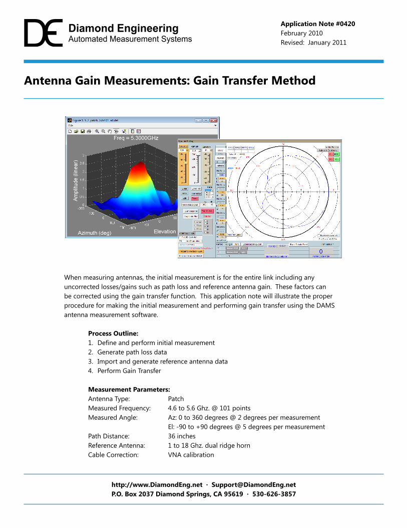
When measuring antennas, the initial measurement is for the entire link including any uncorrected losses/gains such as path loss and reference antenna gain. These factors can be corrected using the gain transfer function. This application note will illustrate the proper procedure for making the initial measurement and performing gain transfer using the DAMS antenna measurement software. Process Outline: 1. Define and perform initial measurement 2. Generate path loss data 3. Import and generate reference antenna data 4. Perform Gain Transfer Measurement Parameters: Antenna Type: Patch Measured Frequency: 4.6 to 5.6 Ghz. @ 101 points Measured Angle: Az: 0 to 360 degrees @ 2 degrees per measurement El: -90 to +90 degrees @ 5 degrees per measurement Path Distance: 36 inches Reference Antenna: 1 to 18 Ghz. dual ridge horn Cable Correction: VNA calibration Antenna Gain Measurements: Gain Transfer Method http://www.DiamondEng.net · [email protected] P.O. Box 2037 Diamond Springs, CA 95619 · 530-626-3857 Application Note #0420 February 2010 Revised: January 2011
Transcript of Antenna Gain Measurements: Gain Transfer Method · · 2012-02-17be corrected using the gain...
When measuring antennas, the initial measurement is for the entire link including any uncorrected losses/gains such as path loss and reference antenna gain. These factors can be corrected using the gain transfer function. This application note will illustrate the proper procedure for making the initial measurement and performing gain transfer using the DAMS antenna measurement software.
Process Outline:1. Defineandperforminitialmeasurement2. Generate path loss data3. Import and generate reference antenna data4. Perform Gain Transfer
Measurement Parameters:Antenna Type: PatchMeasured Frequency: 4.6 to 5.6 Ghz. @ 101 pointsMeasured Angle: Az: 0 to 360 degrees @ 2 degrees per measurement El: -90 to +90 degrees @ 5 degrees per measurementPath Distance: 36 inchesReference Antenna: 1 to 18 Ghz. dual ridge horn Cable Correction: VNA calibration
Antenna Gain Measurements: Gain Transfer Method
http://www.DiamondEng.net · [email protected]. Box 2037 Diamond Springs, CA 95619 · 530-626-3857
Application Note #0420February 2010Revised: January 2011
2
Diamond Engineering Application Note DAMS-0420
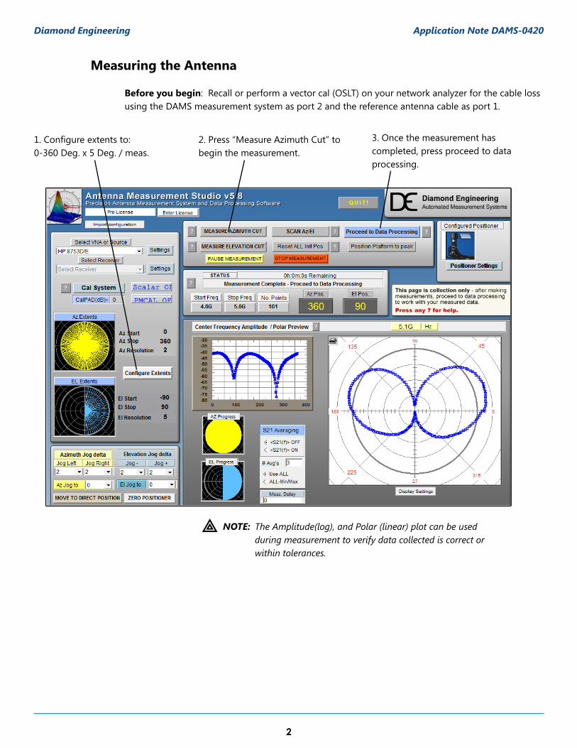
1.Configureextentsto:0-360Deg.x5Deg./meas.
2. Press “Measure Azimuth Cut” to begin the measurement.
3. Once the measurement has completed, press proceed to data processing.
; NOTE:
Measuring the Antenna
Before you begin: Recall or perform a vector cal (OSLT) on your network analyzer for the cable loss using the DAMS measurement system as port 2 and the reference antenna cable as port 1.
The Amplitude(log), and Polar (linear) plot can be used during measurement to verify data collected is correct or within tolerances.

3
Diamond Engineering Application Note DAMS-0420
Storing Measurement Data
When entering the Data Processing section after making a new measurement the data is stored and displayed in the active register (reg0). The default description is titled “New Measurement <completion date/time>”. At this point we will store the data to a register then save reg 1-4 for a hard copy of the original measured data. The steps below illustrate this procedure.
Typical post-measurement procedure:
1. Store data to Reg 12. Change description if desired 3. Save Reg 1-4 to disk
1. Store to Reg1
3. Save Reg. 1-4
Active Register containing new measurement
2. Reg1 Description

4
Diamond Engineering Application Note DAMS-0420
Path Loss and Reference Antenna Data
The Path Loss and Reference Antenna data is calculated based on the data that is currently in the Active Register (reg 0) When completed the data will be accessible to any functions that require it. Thedatacanalsoberecalledintotheactiveregisterformodificationorcopyingtoanotherfile.An.RPLfilewillbegeneratedalong-sidetheoriginalReg1-4.DATfilethatyousave.
m IMPORTANT:The.RPLand.DATfilesmustbemovedtogethertoviewonanothercomputer.
Generate the path loss for your measurement, Enter the correct distance, select the unit of measurement and press “Calculate” , Press continue to return.
Import reference antenna data from .txt file. The format of the file is as follows:
<freq in GHz> <tab> <dBi gain>
Each line being a new frequency the frequencies of your measurement MUST fall within the limits of the imported reference file.
Path Loss Module
Reference Antenna Module
Samplereferencefile:
(FREQ) (GAIN)

5
Diamond Engineering Application Note DAMS-0420
Gain Transfer
The gain transfer function will use the previously generated path loss and reference data to calculate the dBi gain of the measured antenna across all angles and frequencies. Corrected data will be stored into Reg4 and the Active Register (reg0).
After calculating, save reg-1-4 to theharddrivethisfilewillcontainoriginal and calculated data including path and REF. data.
2. Path loss and REF buttons must be green indicating data is present.
1. Measurement data mustbe present in Reg 1
3. Run Gain Transfer function
ResultantAUT Gain Data(Also in Reg0)
Data processing page after Gain Transfer has been completed
Gain Transfer Module
To Perform Gain Transfer:

6
Diamond Engineering Application Note DAMS-0420
Antenna Gain Pattern
Once the gain transfer has been completed the antenna pattern can be plotted in a number of ways,thequickestwaytoanalyzethemaxgainpositionsandfrequenciesiswiththepolarplot.Upto4antennatracescanbeplottedatonetime.Theradiationpatternforanyfrequencyoraxiscanbe displayed simply by moving the sliders to the desired setting.
Locating maximum gain frequency / angle: 1. Select 20Log to view the gain in dB.2. Press “Go to Max signal” and plot will be changed to plot with the maximum gain. 3. Max gain value for specified frequency/cut will be displayed left of polar plot.
(Max Gain for displayed pattern / freq.)2. Go to Max1. Display 20Log
Antenna azimuth pattern showing a peak gain of 8.86 dBi at 15 degrees elevation