
Antenna design essentials for SIGFOX Ready™ devices - Techinal White Paper
40
TECHNICAL WHITE PAPER Antenna design for end products operating on the SIGFOX network
-
Upload
sigfox -
Category
Technology
-
view
881 -
download
3
Transcript of Antenna design essentials for SIGFOX Ready™ devices - Techinal White Paper

TECHNICAL WHITE PAPERAntenna design for end products operating on the SIGFOX network

2 / 40 TECHNICAL WHITE PAPER - Antenna design for end products operating on the SIGFOX network
NOTICE: The contents of this document are proprietary of SIGFOX and shall not be disclosed, disseminated, copied, or used except for purposes expressly authorized in writing by SIGFOX.
3 / 40© Copyright SIGFOX. All rights reserved
ABSTRACT
In this document, several aspects of antenna design and integration are developed. The document focuses on SIGFOX IOT application and small form factor devices.The importance of implementing a high-performance antenna in a device is demonstrated by
analyzing the SIGFOX radio link budget.Theories are then developed to explain why antennas can be extremely sensitive to their environment and may therefore have varying performance (e.g. when held compared to standing alone). Using the same arguments, it is shown that the same antenna can have different behavior when implemented in two distinct device architectures. This leads to an initial finding that for each device development, a specific antenna design, or at least antenna tuning, must be carried out.Then, the most important physical parameters that impact antenna characteristics and behavior are presented. Several typical antenna topologies, miniaturization techniques, and manufacturing techniques applicable to SIGFOX IOT applications and small form factor devices are listed.Advice regarding off-the-shelf antennas is given to explain why antenna performance depicted in datasheets may differ from “real-life implementation” performance.A selection tool will help the reader to select the best antenna topology for the device, based on several parameters such as expected performance, integration or miniaturization level, and design complexity.To close the document, a simple method that roughly estimates devices radiated performance is given. This method does not involve very expensive equipment, such as anechoic chambers, and is relatively easy to set up.
DISCLAIMER
The White Paper and the information contained herein (collectively, the“Information”) is provided to you (both the individual receiving this document and any legal entity on behalf of which such individual is acting) (“You” and “Your”) by SIGFOX SA, on behalf of itself and its affiliates (“SIGFOX”) for informational purposes only.
• You are responsible of making Your own assessments concerning the Information and are advised to verify all representations, statements and Information contained in this White Paper before using or relying upon any of the Information.
• SIGFOX is providing the Information to you “AS IS”. • Although SIGFOX has exercised reasonable care in providing the Information to You, SIGFOX
does not warrant the accuracy of the Information and is not responsible for any damages arising from Your use of or reliance upon the Information.
• SIGFOX disclaims all warranties, express or implied, including, but not limited to, warranties of merchantability, fitness for a particular purpose, satisfactory quality, or non-infringment.
• You acknowledge that your use of the Information is at your sole risk. In no event shall SIGFOX be liable for any direct, indirect, incidental, special or consequential damages, howsoever caused and whether or not such losses are foreseeable, even if that party has been advised (or is otherwise aware) of the possibility of such losses in advance, including, but not limited to, damages for loss of profits, loss of orders, loss of goodwill, of revenue, loss of data, cost of procurement of substitute goods or services, loss resulting from damage to image or reputation, or other intangible losses, resulting from the use of the white paper

4 / 40 TECHNICAL WHITE PAPER - Antenna design for end products operating on the SIGFOX network
TABLE OF CONTENTS
Purpose of the document 6Acronyms 6Reference documents 6
1. Introduction 7
2. Antenna: a critical component for a device operating on the SIGFOX network 8
• 2.1 SIGFOX Radio link budget 8
• 2.2 Link between SIGFOX classes and antenna performance 8
3. Antenna: a very sensible component 9
• 3.1 A little bit of theory 9
• 3.2 Sensitivity to the environment 10
• 3.3 Sensitivity to the design integration 10
4. Antenna design technical considerations 12
• 4.1 Antenna parameters that matter 12
• 4.2 The earlier the better 13
• 4.3 Some antenna topologies 13
• 4.4 Miniaturization technics 18
• 4.5 Antenna manufacturing technologies 20
• 4.6 Advices on off-the-shelf internal antenna integration 22
5. Antenna topology selection Tool 24
• 5.1 External antennas 24
• 5.2 Integral antennas 25

5 / 40© Copyright SIGFOX. All rights reserved
6. Conclusions 27
7. Appendix A: Antenna parameters definitions 28
• 7.1 VSWR and Return Loss 28
• 7.2 Efficiency 29
• 7.3 Directivity 29
• 7.4 Gain 29
• 7.5 EIRP and ERP 30
• 7.6 Antenna bandwidth 31
• 7.7 Polarization 32
• 7.8 Radiation pattern 33
8. Appendix B: A method to assess your antenna design without using
expensive equipment 34
• 8.1 Measurement procedure 35
• 8.2 Measurement post-processing 37
9. Appendix C: RF Anechoic chamber 37
6 / 40 TECHNICAL WHITE PAPER - Antenna design for end products operating on the SIGFOX network
PURPOSE OF THE DOCUMENTThe purpose of this white paper is to help device manufacturers with antenna design and integration. The document is targeting those new to RF/antennas, and will give them some insights in antenna design.This document will mainly highlight good practices in antenna design and help the reader understand and avoid the usual mistakes in integrated antenna design.
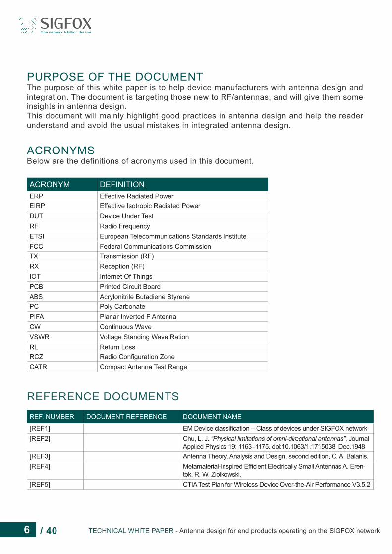
ACRONYMSBelow are the definitions of acronyms used in this document.
REFERENCE DOCUMENTS
ACRONYM DEFINITIONERP Effective Radiated PowerEIRP Effective Isotropic Radiated PowerDUT Device Under TestRF Radio FrequencyETSI European Telecommunications Standards InstituteFCC Federal Communications CommissionTX Transmission (RF)RX Reception (RF)IOT Internet Of ThingsPCB Printed Circuit BoardABS Acrylonitrile Butadiene StyrenePC Poly CarbonatePIFA Planar Inverted F AntennaCW Continuous WaveVSWR Voltage Standing Wave RationRL Return LossRCZ Radio Configuration ZoneCATR Compact Antenna Test Range
REF. NUMBER DOCUMENT REFERENCE DOCUMENT NAME
[REF1] EM Device classification – Class of devices under SIGFOX network[REF2] Chu, L. J. “Physical limitations of omni-directional antennas”, Journal
Applied Physics 19: 1163–1175. doi:10.1063/1.1715038, Dec.1948[REF3] Antenna Theory, Analysis and Design, second edition, C. A. Balanis.[REF4] Metamaterial-Inspired Efficient Electrically Small Antennas A. Eren-
tok, R. W. Ziolkowski.[REF5] CTIA Test Plan for Wireless Device Over-the-Air Performance V3.5.2
7 / 40© Copyright SIGFOX. All rights reserved
1 - INTRODUCTION
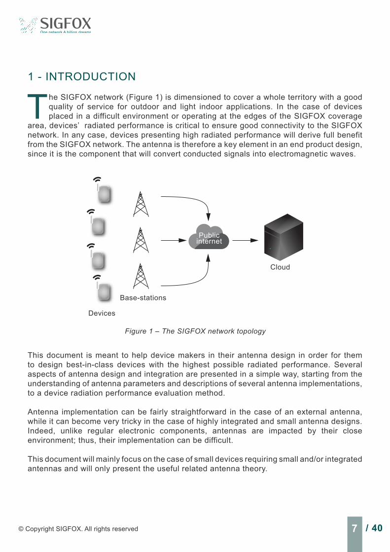
The SIGFOX network (Figure 1) is dimensioned to cover a whole territory with a good quality of service for outdoor and light indoor applications. In the case of devices placed in a difficult environment or operating at the edges of the SIGFOX coverage
area, devices’ radiated performance is critical to ensure good connectivity to the SIGFOX network. In any case, devices presenting high radiated performance will derive full benefit from the SIGFOX network. The antenna is therefore a key element in an end product design, since it is the component that will convert conducted signals into electromagnetic waves.
Figure 1 – The SIGFOX network topology
Devices
Base-stations
Cloud
Public internet
This document is meant to help device makers in their antenna design in order for them to design best-in-class devices with the highest possible radiated performance. Several aspects of antenna design and integration are presented in a simple way, starting from the understanding of antenna parameters and descriptions of several antenna implementations, to a device radiation performance evaluation method.
Antenna implementation can be fairly straightforward in the case of an external antenna, while it can become very tricky in the case of highly integrated and small antenna designs. Indeed, unlike regular electronic components, antennas are impacted by their close environment; thus, their implementation can be difficult.
This document will mainly focus on the case of small devices requiring small and/or integrated antennas and will only present the useful related antenna theory.

8 / 40 TECHNICAL WHITE PAPER - Antenna design for end products operating on the SIGFOX network
2 - ANTENNA: A CRITICAL COMPONENT FOR A DEVICE OPERATING ON THE SIGFOX NETWORK
2.1 SIGFOX Radio link budgetThe SIGFOX network is dimensioned based on a given radio link budget, assuming a certain radiated power level from the devices as described in [REF1]. It means that the SIGFOX network is dimensioned for devices with good radiated performance.Devices with low radiated performance may be able to operate under the SIGFOX network, but will have some limitations due to weaker coverage.
A SIGFOX classification [REF1] is used to let the end product makers know:• What class they should target according to their application and coverage needs• What class their device belongs to and thus what coverage they can expect
2.2 Link between SIGFOX classes and antenna performance.As part of the SIGFOX Ready TM certification for end products, the maximum ERP (Effective Radiated Power) of the Device Under Test (DUT) is measured to define the quality of service it will restore while operating the SIGFOX deployed network. As shown in the equation below, the result of this test is mainly impacted by the antenna design quality, since all SIGFOX Ready TM RF chipsets provide same limited RF conducted power depending on the operation zone: ERPdBm= Conducted_RF_PowerdBm + Antenna_GaindBm Equation 1
Based on this ERP measurement, the class of device is determined as presented in Table 1. This table summarizes the link between SIGFOX classes of the end products and their antenna gain. The antenna gain computations assume an available RF power of 14dBm in ETSI (RCZ 1) regions and 22dBm in FCC (RCZ2) regions at the antenna port. This table is to be updated with other RCZ when available.
Note: It is possible to increase the conducted RF power at the antenna port to reach the 0u class with a non-optimized antenna. However, this only works for devices using SIGFOX uplink connectivity. For devices using both uplink and downlink connectivity, this action will lead to an unbalanced link budget, and will be noticed by the end user, who will be able to send messages in areas where he will not be able to receive messages.
Table 1 - Uplink SIGFOX device classes definition for RCZ1 and RCZ2
RCZ 1 RCZ 2
ERP ETSI (dBm)
EIRP ETSI (dBm)
Antenna gain (dBi)
ERP FCC (dBm)
EIRP FCC (dBm)
Antenna gain (dBi)
Class 0u >12 >14.15 >0.15 >20 >22.15 >0.15
Class 1u >7 >9.15 >-4.85 >15 >17.15 >-4.85
Class 2u >0 >2.15 >-11.85 >5 >7.15 >-15.85
Class 3u <0 <2.15 <-11.85 <5 >7.15 <-15.85

9 / 40© Copyright SIGFOX. All rights reserved
It must be noted that SIGFOX Ready TM certification for end products cannot replace ETSI or FCC certification, which are regulatory and mandatory certifications. Both SIGFOX and regulatory certifications should be completed.
3 - ANTENNA: A VERY SENSITIVE COMPONENTIn this section, an explanation of why antennas are sensitive to their surroundings, and why they should be treated differently from other electronic components, is given.
3.1 A little bit of theory
What is an antenna?A conductive structure in which an alternating electric current flows (RF signal) generates electric and magnetic fields. If the generated fields are strong enough, they will manage to “escape” from the structure into free space and become radiated fields. The strength of those fields depends, of course, on the electric current magnitude, but also on the structure’s dimensions and characteristics.
An antenna is such a structure, dimensioned so that most of the generated fields escape the close surrounding area of the antenna, called reactive area, and become radiated fields. The optimal dimensions of an antenna can vary depending on its type (radiation mechanism). For instance, in the case of a dipole, the antenna size will be optimal when it reaches half a wavelength at operating frequency.An antenna is a reciprocal device, which means that it has the same properties when transmitting as when receiving. Assuming an antenna in TX mode can generate a known electromagnetic power density for a given electrical current, then, the same electromagnetic power density will generate the same amount of electric current in this antenna used in Rx mode.
Antenna reactive and far field regionsIn order to understand why an antenna is a sensitive component, it is important to know that the space around an antenna can be divided in two distinct areas (Figure 2):• The near field area, where the reactive fields (looping back to the antenna) predominate,
and where an object will disturb the antenna’s behavior and characteristics. In this area, the electric and magnetic fields’ orientation and intensity depend on the antenna type. If those fields are disturbed, the antenna’s behavior and properties are impacted.
• The far field area, where radiating fields (not going back to the antenna) predominate, and where an object will not disturb the antenna. It will only disturb the propagation of the electromagnetic waves coming from the antenna, not the antenna’s properties. The far field area starts at a distance of 2D^2
λ from the antenna, where D is the antenna’s maximum dimension, and λ the wavelength at operating frequency.
An intermediate area called the radiating near field area is also described in the literature.

10 / 40 TECHNICAL WHITE PAPER - Antenna design for end products operating on the SIGFOX network
This is the area where both near and far fields coexist.
Nearfield
Transmiter
Boundary
FarField
3.2 Sensitivity to the environmentAs previously explained, an object will disturb an antenna when placed in its near field area. This is the reason why a wireless device will have a distinct radiated performance depending on its environment. For instance, a device placed against a wall will not behave as if it were in free space or held by a user. Therefore, it is important to consider the different use cases when performing the integration of an antenna.
It should be noted that each antenna topology has a different level of sensitivity to its environment. In fact, depending on their radiation mechanism, they can be more or less sensitive to their nearby environment.
For instance, small loop antennas are usually less sensitive to the body than more classic monopole-type antennas. However, small loop antennas are also much less efficient than monopole-type antennas. In the case of a hand-held device, the choice of antenna topology will be a tradeoff between pure efficiency and sensitivity to the hand user.
3.3 Sensitivity to the design integration
Sensitivity due to the antenna’s surroundingsFor the same reason that an antenna is sensitive to a nearby object, it will be also sensitive to the other device components (e.g. batteries, screws, RF shielding) as well as the device casing. This is a key point, because it means that the antenna must be designed and integrated in consideration of every component of the end product. In fact, an antenna designed with no regard for the device’s mechanics will not show optimized behavior once placed in its end environment.
This is also one of the reasons why off-the-shelf antennas often need some additional matching components in order to be re-tuned to their end environment, and may not perform as described in the datasheet.
Figure 2 - Near field and far field area illustration

11 / 40© Copyright SIGFOX. All rights reserved
Sensitivity due to the antenna topologiesIn the case of IOT (Internet Of Things), small form factor devices predominate, which means that antennas need to be as small as possible to allow their integration inside small devices. In that case, bulky half wavelength antennas such as dipoles are avoided, and quarter wavelength or smaller antennas are better options. The problem with this second antenna type is that, unlike half wavelength antennas, they need and use the other metallic parts of the device, such as the PCB ground plane, to radiate. This unfortunately implies that the whole device somehow becomes the antenna and that the size of the ground plane will impact the device’s radiated performance and antenna characteristics.
In Figure 3, the case of a canonical monopole mounted over a large ground plane is illustrated. The figure shows that the currents are flowing through the whole ground plane even far from the antenna. Those currents participate in the antenna’s radiation mechanism. Thus, if the ground plane is reduced, the current distribution will be modified, as will the antenna’s radiation and electrical properties.
This is true for many antenna topologies using a ground plane in their radiation mechanism.
Figure 4 shows the impact of reducing the size of the PCB on a folded monopole antenna performance. This is a typical antenna implementation for a small SIGFOX device. A small peak efficiency drop is noticeable, as well as significant operating frequency bandwidth reduction.
Figure 3 - Example of a monopole surface current distribution
Figure 4 - PCB size impact on antenna performance
Foldedmonopole on a
large PCB
80mm20mm
Foldedmonopole on a
small PCB
0,70
Tota
l effi
cien
cy (
dB)
Freq (GHz)
Small PCB Large PCB
-5
-10
-15
-20
-25
0,8 10,9 1,1
12 / 40 TECHNICAL WHITE PAPER - Antenna design for end products operating on the SIGFOX network
In the case of a small device, the ground plane size and shape are often dictated by the device’s form factor and size, and are not optimized for the selected antenna. Several antenna parameters are impacted by a non-optimal ground plane, such as:• Frequency Bandwidth (reduced)• Antenna radiation efficiency (lowered)• Radiation pattern (modified – usually less directivity with a small ground plane)
Consequently, an antenna must be designed or at least tuned specifically for each design.
4 - ANTENNA DESIGN: TECHNICAL CONSIDERATIONSIn this section, several technical points regarding antenna design and integration are developed, such as basic antenna topologies, miniaturization techniques, and manufacturing technologies.
4.1 Antenna parameters that matterHere is a short list of important parameters to consider during antenna design:
• Antenna volume: The volume of an antenna directly limits its bandwidth and radiation efficiency (limits defined by Chu and Harrington [REF2]). Thus, enough volume should be reserved for the antenna. The antenna is actually a component that often takes up a large percentage of a wireless device total volume.
• Antenna location: The location of an antenna is critical and will have an impact on almost all antenna parameters. The best location will depend on the antenna’s topology. There is no universal law for this parameter.
• Casing material: Materials used to manufacture the device casing can be critical for the antenna’s performance. This is even more critical for small antennas. If the dielectric material properties are available, it is better to choose a material with low permittivity and dielectric losses that are as low as possible. Plastic such as ABS and PC are very common and are appropriate materials for casing.
• Metal casing: In the case of integral antennas, partially metal casing can be an option, though the antenna’s integration will become more challenging. In most cases, a metal casing will have to be connected to the antenna’s ground plane to avoid unintentional resonances, which may lead to a decline in performance.
Full metal casings should be avoided in the case of integral antennas.
• Components around the antenna: The best way to disturb an antenna is to place a metallic part next to it. Antenna performance can be impacted by a metallic structure lying next to it. Therefore, it is best to avoid placing large electronic components (e.g. batteries, cameras, speakers) close to the antenna, or to take them into account while designing or tuning the antenna. The device’s mechanical layout should be frozen before the antenna’s

13 / 40© Copyright SIGFOX. All rights reserved
final tuning (any late changes can impact the antenna’s tuning).
At some point during the design and test phases of your device’s antenna, you will need to build a prototype. It is important to have a prototype that is made of the same materials and uses the same manufacturing process as the end product. A casing built using a 3D printer, for instance, may have different electrical properties than the final version using a mold (even if the same material is used due to different plastic density). It may be a good idea to build a first prototype with a 3D printer, to evaluate the achievable performance, but remember to check the first production devices and retune the antenna if needed.
4.2 The earlier the betterAs soon as a wireless device design starts, the antenna should be considered, especially if it is the SIGFOX highest device class with integral antenna. Indeed, the earlier the antenna design is taken into account, the easier it will be to find the antenna topology that best fits your device in terms of implementation and performance.
Antenna performance should also be estimated as soon as possible if very high performance is expected.
If the antenna design starts too late, three things can happen:• The antenna works well in your device design without modifying it (unlikely to happen).• The antenna does not work well, but you can make some design changes to achieve target
performance, meaning there will be some delays in your schedule.• The antenna does not radiate enough, and you cannot modify your device design, thus,
you will not achieve the expected radiated performance.
A hardware update of an already existing product can sometimes be a good opportunity to add some functionalities such as SIGFOX connectivity. In that case, a specific antenna implementation study must be carried out to find a good antenna topology that fits the device design and evaluate the achievable radiated performance.
4.3 Some antenna topologiesIn this section, a few basic antenna topologies are presented, on which most modern integrated antenna topologies are based.
A detailed description of these antenna topologies can be found in [REF3].
Dipole antennaOften consisting of two straight conductive rods or wires, with a total length of half the radiated/received wavelength (thus called half wavelength antenna) (Figure 5), the dipole antenna is probably the simplest and most widely used type of antenna. This kind of antenna is omnidirectional, i.e. it has a non-directional radiation pattern (circular pattern) in a given plane (the plane that is actually orthogonal to the rods).

14 / 40 TECHNICAL WHITE PAPER - Antenna design for end products operating on the SIGFOX network
As shown above in Figure 6, the dipole antenna radiates (and receives) equally well in all horizontal directions (H plane), while its directivity drops down to zero on the antenna axis. Neglecting electrical inefficiency (e.g ohmic losses for a dipole antenna), a dipole has a typical gain of 2.15 dBi.
Dipole are excellent candidates in the case of external antennas if volume is not a constraint. They are almost independent from the rest of the device integration since they don’t use the device structure to radiate (e.g. ground plane).
λ/2
λ/4 λ/4
l
VTransmission line (75Ω)
Figure 5 - Illustration of a dipole antenna
E-Plane
0
180
270 90
315
225135
45
H-Plane
0
180
270 90
315
225135
45
Figure 6 - Dipole radiation pattern in E and H plane
15 / 40© Copyright SIGFOX. All rights reserved
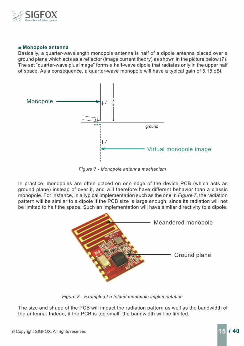
Monopole antennaBasically, a quarter-wavelength monopole antenna is half of a dipole antenna placed over a ground plane which acts as a reflector (image current theory) as shown in the picture below (7). The set “quarter-wave plus image” forms a half-wave dipole that radiates only in the upper half of space. As a consequence, a quarter-wave monopole will have a typical gain of 5.15 dBi.
In practice, monopoles are often placed on one edge of the device PCB (which acts as ground plane) instead of over it, and will therefore have different behavior than a classic monopole. For instance, in a typical implementation such as the one in Figure 7, the radiation pattern will be similar to a dipole if the PCB size is large enough, since its radiation will not be limited to half the space. Such an implementation will have similar directivity to a dipole.
The size and shape of the PCB will impact the radiation pattern as well as the bandwidth of the antenna. Indeed, if the PCB is too small, the bandwidth will be limited.
Figure 7 - Monopole antenna mechanism
4λ
ground
I
I
Monopole
Virtual monopole image
Figure 8 - Example of a folded monopole implementation
Meandered monopole
Ground plane

16 / 40 TECHNICAL WHITE PAPER - Antenna design for end products operating on the SIGFOX network
Slot antennaSlot antennas are quite simple structures, as they only consist of a large metal surface with a slot cut out. The shape and size of the slot determine the antenna’s resonant frequency.
They can be one-half wavelength long (Figure 9a) if they are terminated slots, and can be one-quarter wavelength long (Figure 9b) if the slot is placed at the edge of the metal surface and left open.
Slot antennas can be a simple straight cut or have a more complex shape to reduce their size or to better integrate them on a PCB (Figure 10).
Metallic groundplane
λg is the equivalent wavelength in the dielectric substrate
50Ώ linefeed
Slot
λg/2 λg/4
(a) (b)
Figure 9 - Terminated (a) and opened slot antennas (b)
Metallic groundplane
50Ώ linefeed
Slot
λg/4
Figure 10 - Example of complex shaped slot antenna
17 / 40© Copyright SIGFOX. All rights reserved
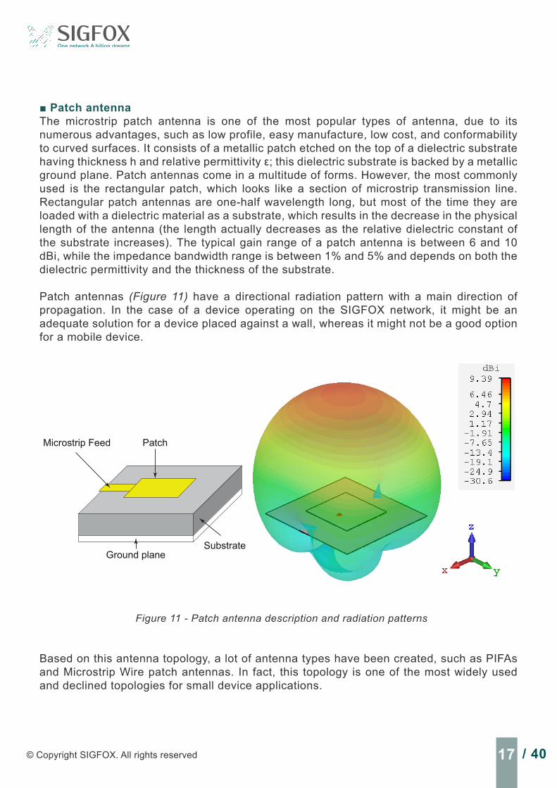
Patch antennaThe microstrip patch antenna is one of the most popular types of antenna, due to its numerous advantages, such as low profile, easy manufacture, low cost, and conformability to curved surfaces. It consists of a metallic patch etched on the top of a dielectric substrate having thickness h and relative permittivity ε; this dielectric substrate is backed by a metallic ground plane. Patch antennas come in a multitude of forms. However, the most commonly used is the rectangular patch, which looks like a section of microstrip transmission line. Rectangular patch antennas are one-half wavelength long, but most of the time they are loaded with a dielectric material as a substrate, which results in the decrease in the physical length of the antenna (the length actually decreases as the relative dielectric constant of the substrate increases). The typical gain range of a patch antenna is between 6 and 10 dBi, while the impedance bandwidth range is between 1% and 5% and depends on both the dielectric permittivity and the thickness of the substrate.
Patch antennas (Figure 11) have a directional radiation pattern with a main direction of propagation. In the case of a device operating on the SIGFOX network, it might be an adequate solution for a device placed against a wall, whereas it might not be a good option for a mobile device.
Microstrip Feed Patch
Ground planeSubstrate
Figure 11 - Patch antenna description and radiation patterns
Based on this antenna topology, a lot of antenna types have been created, such as PIFAs and Microstrip Wire patch antennas. In fact, this topology is one of the most widely used and declined topologies for small device applications.

18 / 40 TECHNICAL WHITE PAPER - Antenna design for end products operating on the SIGFOX network
4.4 Miniaturization techniquesThe size of an antenna is defined by the wavelength at its operating frequency. For a device operating on the SIGFOX network in the RCZ1 at 868 MHz, the wavelength in free space is 34.5cm, which means that a dipole or patch would measure 17.3 cm, and a monopole 8.6 cm. Of course, in the case of a small device, these dimensions are too large. Fortunately, several techniques exist to miniaturize antennas, but they come at a cost. In fact, as the size of an antenna is limiting its bandwidth and its radiation efficiency, thus, miniaturizing an antenna will decrease the efficiency or the bandwidth, or both.
In this section, some common miniaturization techniques are presented.
Antenna loading
• Add a capacitive load at the open end of the antenna (a) or an inductive load at the feed point (b).
• Loading can be done by shaping the antenna or adding lumped components on the antenna structure.
(a) (b)
Antenna loading using materials
• Electrical characteristics of surrounding antenna materials (εr,μr) can be used to reduce the antenna size.
• High permittivity material such as ceramic material can be used at SIGFOX operating frequencies
• Magnetic materials only work for low frequencies and are not appropriate at SIGFOX frequencies.
Air
λ0
4h=
Dielectric
λ0
4 εrμr
h=
Example: The size of a monopole being λ0
4 εrμr
h= , (where εr is the permittivity
and μr the permeability) increasing εr and μr helps reduce the size of the monopole.

19 / 40© Copyright SIGFOX. All rights reserved
Use short circuits
• It is possible to reduce the size of a patch antenna by a factor of 2, placing a short circuit at the middle of the patch (where the E-field is null).
• PIFA and patch antennas have slightly different radiation properties due to miniaturization.
λg
2α =~
Patch antenna
λg
4α =~
PIFA
Increase current path length
• Planar antennas: slit and notches are inserted in the structure to increase the surface current path
• Wire antennas: meandered lines or coils are used to increase the surface current path
λg
2α =~
Patch antenna
Monopole antenna
λg
2α <
λg
4α =~ λg
4α <
Exotic structures
On top of classic miniaturization techniques, several exotic antenna structures have been developed allowing strong antenna miniaturization.
Example: Metamaterial inspired antennas
• Extremely small antenna• Naturally matched to 50 ohms• Usually highly efficient but very narrow
band antennas
A metamterial inspired antenna design (REF4)
20 / 40 TECHNICAL WHITE PAPER - Antenna design for end products operating on the SIGFOX network
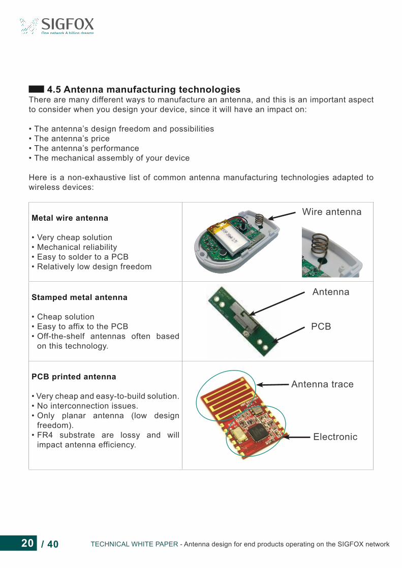
4.5 Antenna manufacturing technologiesThere are many different ways to manufacture an antenna, and this is an important aspect to consider when you design your device, since it will have an impact on:
• The antenna’s design freedom and possibilities• The antenna’s price• The antenna’s performance• The mechanical assembly of your device
Here is a non-exhaustive list of common antenna manufacturing technologies adapted to wireless devices:
Metal wire antenna
• Very cheap solution• Mechanical reliability• Easy to solder to a PCB• Relatively low design freedom
Wire antenna
Stamped metal antenna
• Cheap solution• Easy to affix to the PCB• Off-the-shelf antennas often based
on this technology.
Antenna
PCB
PCB printed antenna
• Very cheap and easy-to-build solution.• No interconnection issues.• Only planar antenna (low design
freedom).• FR4 substrate are lossy and will
impact antenna efficiency.
Antenna trace
Electronic

21 / 40© Copyright SIGFOX. All rights reserved
Ceramic antenna
• High dielectric properties of ceramic material used for miniaturization.
• Often quite narrow band antennas.• Off-the-shelf antennas often based
on this technology.• Difficult to make a custom design.
Ceramic material
Metallization
LDS antenna (Laser Direct Structuring)
• Fully 3D shaped antenna (only few technology limitations) highest antenna design freedom best performance.
• Antenna trace directly “printed” on the antenna carrier.
• Highest level of integration possible.• Only few manufacturers support this
technology.• Plastic antenna carrier is needed.
Antenna copper trace
Antenna plastic carrier
Flex antenna
• Antenna printed on a thin polyimide substrate and glued to a plastic antenna carrier.
• Design flexibility• Good tolerances• Plastic antenna carrier is needed
Antenna Flex PCB
Antenna carrier
Stand-aloneflex antenna
Repeatability should be taken into account in the manufacturing technology selection. In fact, it is crucial to make sure that every device will have the same radiated performance and thus that antenna design is reliable and repeatable.
22 / 40 TECHNICAL WHITE PAPER - Antenna design for end products operating on the SIGFOX network
4.6 Advice on off-the-shelf internal antenna integrationUsing an off-the-shelf antenna can be an excellent idea, since they are relatively cheap and only require little development effort. However, some precautions need to be taken. In this section, some advice is given to help you succeed in implementing such an antenna in your device.
Differences between antenna performance presented in datasheets and real-life performanceAntenna performance announced in datasheets usually applies to the reference design used to characterize the antenna. Thus, if your integration differs from this reference design, the performance will most likely be different. Since the reference design is probably the best configuration for the tested antenna, you should expect lower performance using a different implementation.
Here is a list of parameters that will impact the antenna’s performance and behavior when changed compared to the initial datasheet:
• PCB size is quite important, since it is part of the antenna’s radiation mechanism. The same antenna placed on different PCBs will not provide the same performance.
• Antenna location on the PCB is also an important parameter. For instance, a side board antenna cannot be implemented in the middle of a PCB unless specified. In fact, several antenna locations are often evaluated in the datasheets. Select one of them and the antenna should work properly. If you have to place the antenna in another location, a study should be performed to validate the implementation.
• Ground clearance areas defined in the datasheets must be respected. If not, the impact might be:
- different antenna loading configuration, leading to lower radiated performance and antenna frequency detuning.
- complete change of the antenna radiation mechanism, leading to extremely poor antenna efficiency.
• Your device will most likely have a casing enclosing all the electronics, including the antenna, which is probably not the case with the reference design. This casing will have an impact on the antenna frequency tuning and efficiency, depending on the kind of material, its thickness, and the distance between the antenna and the casing. Ideally, the material should be as lossless, as thin, and as far away as possible from the antenna. Of course, this is not often possible, so here is a list of more realistic advice:
- Plastics with dielectric properties similar to ABS are acceptable. Typically, ABS plastic dielectric properties are εr≈3 and tanδ ≈0.01; however, they can vary depending on the material supplier.
- A minimum distance of 1-2 mm should be kept between the antenna and the casing. - A maximum plastic thickness of 2 mm should be respected.
23 / 40© Copyright SIGFOX. All rights reserved
These recommendations are not universal, but they should allow you to integrate an off-the-shelf antenna in your device with only a minimum of matching re-work to retune the antenna, and without any substantial loss in performanc.
Antenna manufacturers can often help you to tune the selected antenna to your specific design. They can also give you some advice for selecting the best antenna solution for your device.
How to read an antenna datasheetAntenna datasheets can substantially differ depending on the antenna manufacturer, which sometimes make them difficult to read and compare.
In fact, antenna manufacturers do not always present the same parameters (see Appendix A for parameter definitions) in their datasheets, even for the same kind of antenna:
• Gain vs efficiency: Most datasheets will only provide one of those two parameters. It can be confusing when comparing two antennas, since they do not compare the same quantity. Furthermore, it is not always stated whether the datasheet refers to radiation or total efficiency, and to total or IEEE gain.
• VSWR vs Return Loss: Most datasheets will only provide one of those two parameters. They give the same information, and you can easily do the conversion from one to the other.
• Frequency bandwidth: The frequency bandwidth is not always defined using the same criteria. For small device antennas, even though most datasheets use the Return Loss to determine the bandwidth, the limit level used to compute the bandwidth can differ.
The units used in datasheets can also cause some confusion. For instance, efficiency can be presented in either dB scale or linear scale. It is easy to make the conversion using equations 2 and 3.
EffdB = 10xLog10 (Efflin) Equation 2
Efflin = 10EffdB
10 Equation 3
Another confusing piece of information is the antenna size or volume defined in antenna datasheet. Indeed, the antenna dimensions presented in datasheets do not always include PCB ground clearance or component-free areas (keep-away distance). In fact, a small antenna that requires a large ground free area could actually occupy a larger volume than
24 / 40 TECHNICAL WHITE PAPER - Antenna design for end products operating on the SIGFOX network
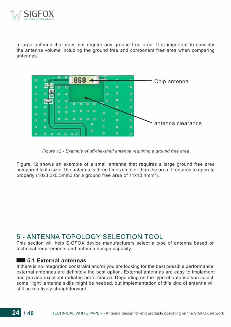
a large antenna that does not require any ground free area. It is important to consider the antenna volume including the ground free and component free area when comparing antennas.
Chip antenna
antenna clearance
Figure 12 - Example of off-the-shelf antenna requiring a ground free area
Figure 12 shows an example of a small antenna that requires a large ground free area compared to its size. The antenna is three times smaller than the area it requires to operate properly (10x3.2x0.5mm3 for a ground free area of 11x10.4mm²).
5 - ANTENNA TOPOLOGY SELECTION TOOLThis section will help SIGFOX device manufacturers select a type of antenna based on technical requirements and antenna design capacity.
5.1 External antennasIf there is no integration constraint and/or you are looking for the best possible performance, external antennas are definitely the best option. External antennas are easy to implement and provide excellent radiated performance. Depending on the type of antenna you select, some “light” antenna skills might be needed, but implementation of this kind of antenna will still be relatively straightforward.

25 / 40© Copyright SIGFOX. All rights reserved
Use the chart below to select the external antenna type according to your requirements:
External Antenna
Half Wave: dipole@868MHz ~ 17cm
quarter wave: monopole@868MHz ~ 8.5cm
miniature: helical antenna@868MHz < 8.5cm
Performance
Design simplicity
Integration level
10
10
0
10
8
1
8
7
3
Plug-and-play solution Little work on antenna location
Requires a ground plane to work
Some matching circuitry may be required
Requires a ground plane to work
For best performance, external antennas should not be placed along the ground plane. The antenna should be kept away from the ground plane (Figure 13).
Antenna
XFigure 13 - Example of bad and good external antenna integration
5.2 Integral antennasIf an integral antenna is required in your device, it is important to evaluate which option is best, depending on the integration level needed and the targeted performance. The effort you want to put into the antenna design is also an important parameter to take into account.
26 / 40 TECHNICAL WHITE PAPER - Antenna design for end products operating on the SIGFOX network
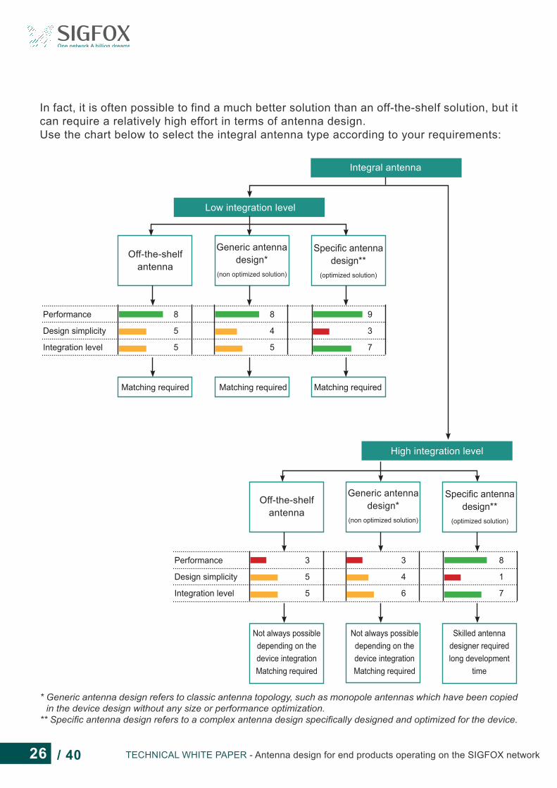
In fact, it is often possible to find a much better solution than an off-the-shelf solution, but it can require a relatively high effort in terms of antenna design.Use the chart below to select the integral antenna type according to your requirements:
Integral antenna
Low integration level
High integration level
Off-the-shelfantenna
Off-the-shelfantenna
Generic antennadesign*
(non optimized solution)
Generic antennadesign*
(non optimized solution)
Specific antennadesign**
(optimized solution)
Specific antennadesign**
(optimized solution)
Performance
Design simplicity
Integration level
Performance
Design simplicity
Integration level
8
5
5
3
5
5
8
4
5
3
4
6
9
3
7
8
1
7
Matching required
Not always possible depending on the device integrationMatching required
Matching required
Not always possible depending on the device integrationMatching required
Matching required
Skilled antennadesigner requiredlong development
time
* Generic antenna design refers to classic antenna topology, such as monopole antennas which have been copied in the device design without any size or performance optimization.
** Specific antenna design refers to a complex antenna design specifically designed and optimized for the device.
27 / 40© Copyright SIGFOX. All rights reserved
6 - CONCLUSIONSSeveral aspects of antenna design and implementation have been presented in this document to help device makers without a strong background in antennas select a good antenna solution for their device operating on the SIGFOX network.
The document also explains why antennas are so sensitive to their environment and why poor implementation can lead to extremely low radiated performance.
It presents the most common antenna topologies and miniaturization techniques and gives some suggestions for preventing confusion when reading an antenna datasheet.
This document will not replace a skilled antenna designer; however, it can help a device maker avoid some common mistakes, for instance, in implementing an off-the-shelf antenna.
28 / 40 TECHNICAL WHITE PAPER - Antenna design for end products operating on the SIGFOX network
7 - APPENDIX A: ANTENNA PARAMETER DEFINITIONSIn this section, some important antenna parameter definitions are given.
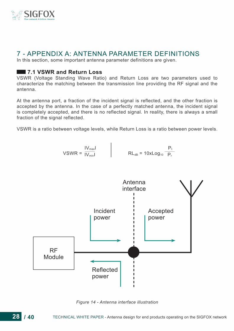
7.1 VSWR and Return LossVSWR (Voltage Standing Wave Ratio) and Return Loss are two parameters used to characterize the matching between the transmission line providing the RF signal and the antenna.
At the antenna port, a fraction of the incident signal is reflected, and the other fraction is accepted by the antenna. In the case of a perfectly matched antenna, the incident signal is completely accepted, and there is no reflected signal. In reality, there is always a small fraction of the signal reflected.
VSWR is a ratio between voltage levels, while Return Loss is a ratio between power levels.
RFModule
Incident power
Reflectedpower
Antenna interface
Acceptedpower
VSWR =
IVmaxIIVminI RLdB = 10xLog10
Pt
Pr
Figure 14 - Antenna interface illustration

29 / 40© Copyright SIGFOX. All rights reserved
These two parameters are often used in antenna datasheets.Using the return loss or the VSWR, it is possible to determine the mismatch loss at the antenna port, as described in the table below:
RL (dB) -15 -10 -6 -4
VSWR 1.4 2 3 4.4
Mismatch loss (dB) 0.14 0.46 1.25 2.2
In the case of a device operating on the SIGFOX network, a minimum return loss of -10 dB over the whole operating frequency band is a good target.If too much signal is reflected, on top of increasing the mismatch losses, this reflected signal will go back to the RF module and possibly make it generate higher harmonics.
7.2 EfficiencyEfficiency defines the capability of an antenna to transform a guided RF signal into a radiated wave. For integrated antennas, efficiency is a very important criterion that can, by itself, characterize the quality and potential of an antenna’s design. In the literature, two kinds of antenna efficiency can be found:
• Radiation efficiency, which is the ratio between the power accepted by the antenna and the radiated power.
• Total efficiency, which is the ratio between the incident power at the antenna port and the radiated power.
Total efficiency takes into account the insertion loss (due to mismatch between the RF line and the antenna input), while radiation efficiency does not.
TotEffdB = RadEffdB - Mismatch_lossesdB Equation 4
These parameters are often used in antenna datasheets.
7.3 DirectivityAn antenna never radiates uniformly over all directions. Such an antenna would be the isotropic antenna which does not exist. Based on this observation, antenna directivity was defined and describes its capacity to concentrate its radiation into one direction. It is the ratio between the radiation intensity in one direction and the average radiation intensity.
It is important to note that directivity does not take into account any kind of losses. For instance, an antenna can have relatively high directivity, while having a low gain if its efficiency is poor.
Another relevant observation to note about directivity is that when directivity increases in

30 / 40 TECHNICAL WHITE PAPER - Antenna design for end products operating on the SIGFOX network
one direction, it automatically decreases in other directions. 7.4 Gain
Antenna gain is very similar to directivity, but takes losses into account. In fact, antenna gain combines antenna directivity and antenna efficiency.
Two definitions of gain can be found in the literature. The total gain, defined in Equation 7, refers to total efficiency, while IEEE gain, defined in Equation 8, refers to radiation efficiency.
TotGaindBi = TotEffdB + DirectivitydBi Equation 5
IEEE GaindBi = RadEffdB + DirectivitydBi Equation 6
Two units can be used to express the gain:• A gain expressed in dBi is normalized compared to the isotropic antenna• A gain expressed in dBd is normalized compared to a dipole antenna exhibiting a maximum
gain of 2.15 dBi.
GaindBd = GaindBi - 2.15 Equation 7
Gain is often a parameter presented in antenna datasheets.
7.5 EIRP and ERPEIRP (Effective Isotropic Radiated Power) and ERP (Effective Radiated Power) are more system criteria than antenna parameters, since they depend on the available power at the antenna port. They describe how much power a device radiates in a given direction. EIRP is the amount of power an isotropic antenna would need to radiate the same amount of power in a given direction as the measured antenna.
EIRPdBm = RF_PowerdBm+ GaindBi Equation 8
While EIRP refers to the isotropic antenna, ERP refers to a perfect dipole antenna with a gain of 2.15dBi. Therefore, the relation between ERP and EIRP values is simply an offset of 2.15dB, as described in the equation below.
ERPdBm = RF_PowerdBm+ GaindBd Equation 9
ERPdBm = EIRPdBm - 2.15 Equation 10
ERP is the parameter used in the SIGFOX device classification certification.
31 / 40© Copyright SIGFOX. All rights reserved
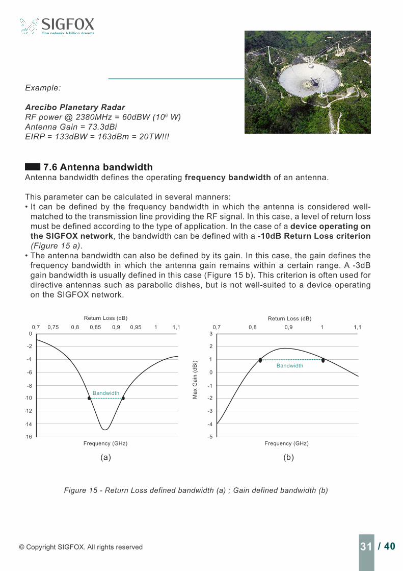
Example:
Arecibo Planetary RadarRF power @ 2380MHz = 60dBW (106 W)Antenna Gain = 73.3dBiEIRP = 133dBW = 163dBm = 20TW!!!
7.6 Antenna bandwidthAntenna bandwidth defines the operating frequency bandwidth of an antenna.
This parameter can be calculated in several manners:• It can be defined by the frequency bandwidth in which the antenna is considered well-
matched to the transmission line providing the RF signal. In this case, a level of return loss must be defined according to the type of application. In the case of a device operating on the SIGFOX network, the bandwidth can be defined with a -10dB Return Loss criterion (Figure 15 a).
• The antenna bandwidth can also be defined by its gain. In this case, the gain defines the frequency bandwidth in which the antenna gain remains within a certain range. A -3dB gain bandwidth is usually defined in this case (Figure 15 b). This criterion is often used for directive antennas such as parabolic dishes, but is not well-suited to a device operating on the SIGFOX network.
0,70
Ret
urn
Loss
(dB
)
Frequency (GHz)
-2
-4
-6
-10
-8
-12
-14
-16
0,75 10,8 0,85 0,9 0,95 1,1
(a)
3
Max
Gai
n (d
Bi)
Frequency (GHz)
2
1
0
-2
-1
-3
-4
-5
0,7 0,8 10,9 1,1
(b)
Figure 15 - Return Loss defined bandwidth (a) ; Gain defined bandwidth (b)
Return Loss (dB)
Bandwidth
Bandwidth
Return Loss (dB)
32 / 40 TECHNICAL WHITE PAPER - Antenna design for end products operating on the SIGFOX network
In the case of small antennas, the return loss is often used to determine the antenna bandwidth, since the gain is not a critical parameter.
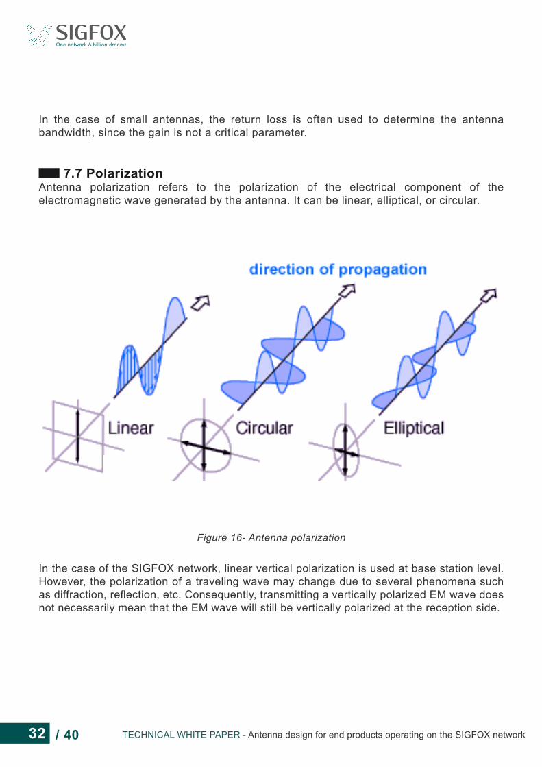
7.7 PolarizationAntenna polarization refers to the polarization of the electrical component of the electromagnetic wave generated by the antenna. It can be linear, elliptical, or circular.
Figure 16- Antenna polarization
In the case of the SIGFOX network, linear vertical polarization is used at base station level. However, the polarization of a traveling wave may change due to several phenomena such as diffraction, reflection, etc. Consequently, transmitting a vertically polarized EM wave does not necessarily mean that the EM wave will still be vertically polarized at the reception side.

33 / 40© Copyright SIGFOX. All rights reserved
7.8 Radiation patternThe antenna radiation pattern is a measure of its far field power or radiation distribution with respect to a particular type of coordinates.
It gives an image of how an antenna radiates in free space.
It is important to note that:• Every single antenna topology has a specific radiation pattern.• The same antenna implemented in two different devices can exhibit different radiation patterns.• Two identical devices can have two different radiation patterns depending on their environment.
Fareld Directivity Abs (phi = 90)
030Phi = 90 0
60 0
180150 150
120 120
90 90-30 -10 0
Figure 17 - Example of a dipole antenna’s 3D and 2D radiation patterns
In the case of a device operating in the SIGFOX network, omnidirectional or dipole-like radiation patterns (Figure 17) are preferred due to the star topology of the network (spatial redundancy).

34 / 40 TECHNICAL WHITE PAPER - Antenna design for end products operating on the SIGFOX network
8 - APPENDIX B: A METHOD FOR ASSESSING YOUR ANTENNA DESIGN WITHOUT USING EXPENSIVE EQUIPMENT
In this section, a streamlined outdoor ERP measurement procedure, compared to the lab measurement performed following the regulation, is presented. It will help the device maker to roughly evaluate the radiated performance of a device operating on the SIGFOX network without involving expensive equipment such as anechoic chambers.
This measurement method only requires a limited setup:• 1 spectrum analyzer• 1 receiving antenna• 1 reference device with known radiated performance (ERP or EIRP)
The method is also quite easy to perform and does not require in-depth knowledge of antenna measurements. Only the use of a spectrum analyzer is needed.
Disclosure: This method is not accurate enough to provide reliable results (due to possible reflection and an uncontrolled environment). The results you will get from this method are only an indication of the performance level you can expect from your device. Therefore, additional testing in an anechoic chamber should be considered for accurate final ERP results.
Polarization is not considered in this measurement method. It is better to select a linearly polarized antenna as reception antenna.
Streamlined ERP measurement setup description:
The proposed light ERP measurement method needs to be performed in an open field environment. Typically a rugby field will work. The spectrum analyzer is positioned on a mast, and a reception antenna is connected to it. The DUT holder in placed in front of the receiving antenna so that both the reception antenna and the DUT are at the same height.
For mobile phone measurements, a minimum distance of about 1.20m is recommended between the measurement antenna and the DUT ([REF5]). In the case of a device as small as those generally operating on the SIGFOX network (maximum dimension < λ/2), a minimum distance of 1.05m is recommended between the measurement antenna and the DUT. To avoid ground reflections, the DUT and the measurement antenna should be placed high enough from the ground, and not too far to minimize the ground reflection impact on the measurement.
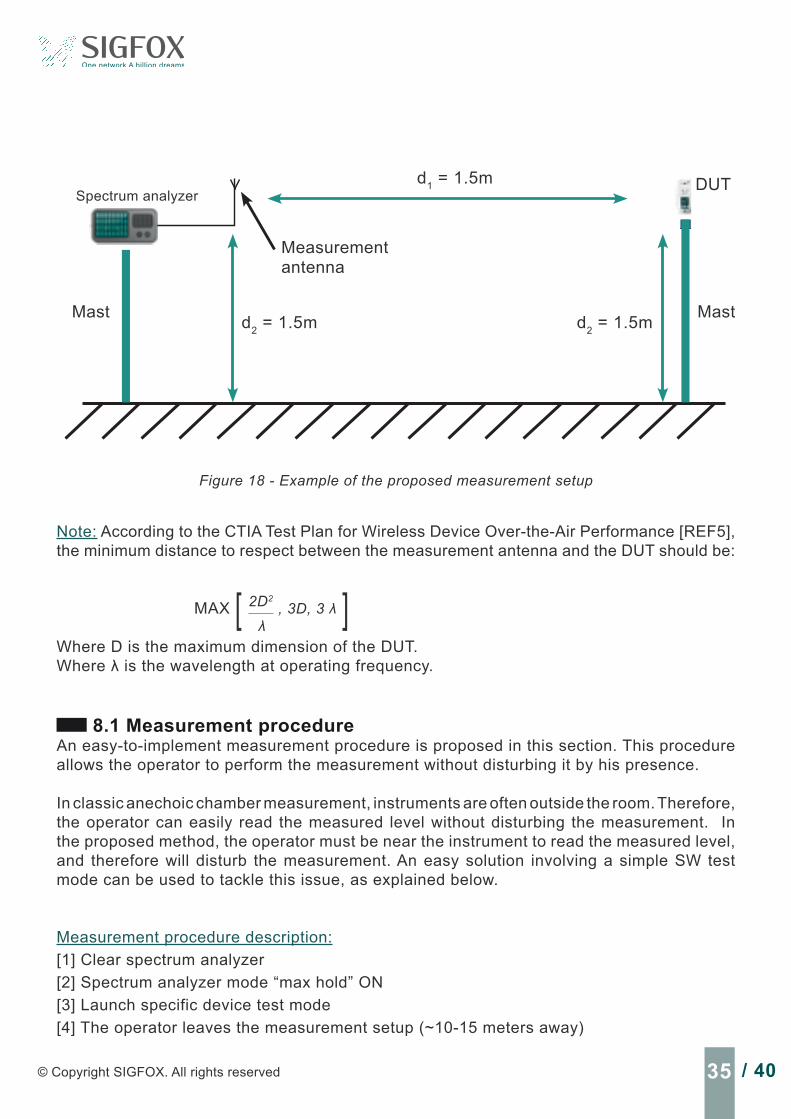
In Figure 18, we recommend placing the DUT 1.5 m away from the reception antenna and 1.5 m away from the ground.
35 / 40© Copyright SIGFOX. All rights reserved
Measurementantenna
d1 = 1.5m
d2 = 1.5m d2 = 1.5mMast Mast
Spectrum analyzerDUT
Figure 18 - Example of the proposed measurement setup
Note: According to the CTIA Test Plan for Wireless Device Over-the-Air Performance [REF5], the minimum distance to respect between the measurement antenna and the DUT should be:
MAX 2D2
λ, 3D, 3 λ[ ]
Where D is the maximum dimension of the DUT.Where λ is the wavelength at operating frequency.
8.1 Measurement procedureAn easy-to-implement measurement procedure is proposed in this section. This procedure allows the operator to perform the measurement without disturbing it by his presence.
In classic anechoic chamber measurement, instruments are often outside the room. Therefore, the operator can easily read the measured level without disturbing the measurement. In the proposed method, the operator must be near the instrument to read the measured level, and therefore will disturb the measurement. An easy solution involving a simple SW test mode can be used to tackle this issue, as explained below.
Measurement procedure description:[1] Clear spectrum analyzer[2] Spectrum analyzer mode “max hold” ON[3] Launch specific device test mode[4] The operator leaves the measurement setup (~10-15 meters away)
36 / 40 TECHNICAL WHITE PAPER - Antenna design for end products operating on the SIGFOX network
[5] Wait until the device SW test mode cycle is over[6] Read the measured level on the spectrum analyzer
The following SW test mode should be implemented in the DUT and used in measurement procedure step [3]:[1] Wait x seconds (the time the operator needs to leave the measurement setup)[2] Mode CW ON[3] Wait y seconds (time for the spectrum analyzer to measure the signal)[4] Mode CW OFF[5] Optional: generate an alert (can be useful to let the operator know the cycle is over)
This measurement procedure should be performed once with the reference device positioned at its highest ERP position (known position).
Then, the reference device is removed from the setup and the DUT is put in its place. The DUT is then measured following the same procedure.
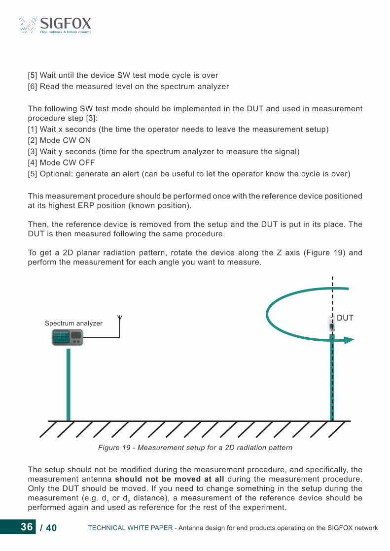
To get a 2D planar radiation pattern, rotate the device along the Z axis (Figure 19) and perform the measurement for each angle you want to measure.
Spectrum analyzerDUT
Figure 19 - Measurement setup for a 2D radiation pattern
The setup should not be modified during the measurement procedure, and specifically, the measurement antenna should not be moved at all during the measurement procedure. Only the DUT should be moved. If you need to change something in the setup during the measurement (e.g. d1 or d2 distance), a measurement of the reference device should be performed again and used as reference for the rest of the experiment.

37 / 40© Copyright SIGFOX. All rights reserved
8.2 Measurement post-processingThe presented method being a relative measurement, it requires knowing the radiated performance of the reference device (in this case, ERP or EIRP). Also, the measurement of both reference device and DUT should be performed following the measurement procedure described above.From these three values, it is quite easy to extract the DUT ERP using the following equation:
ERPDUT = MeasDUT+ ERPREF - MeasREF Equation 11
If the reference device was evaluated in EIRP, then, the following equation should be used.
EIRPDUT = MeasDUT + EIRPREF - MeasREF Equation 12
The proposed method does not require long-term repeatability, because each time you measure a DUT, you compare it to a reference device that is equivalent to calibrate your system each time you do a measurement.
Performing the measurement in an open field avoids reflection from trees or buildings, which would make this method completely unreliable. However, the closer to the ground the measurement is performed, the more reflection from the ground there will be. This is the weak point of this method. These reflections will bring some inaccuracy and error in the measurement. To minimize this problem, the measurement should be performed away from the ground and at a controlled distance between the DUT and the receiving antenna.
Example:The reference Design has an ERP of 14dBm (previously measured in a calibrated setup). The reference device measured level on the spectrum analyser is -20dBm.The DUT measured level is -24dBm.The computed DUT ERP level is then -24+14+20 = 10dBm.
9 - APPENDIX C: RF ANECHOIC CHAMBERAnechoic chambers are very popular tools used to carry out measurements of antenna radiation properties. They have several characteristics that allow accurate and repeatable antenna measurements, which would be very difficult to achieve in an outdoor test range.
An anechoic chamber is a faraday cage with high insulation between the inside and the outside. It is very important not to disturb this property with external noise or signal during the DUT measurement. This property is essential in sensitivity measurements.
Radio-absorbing materials are placed on the walls, floor, and ceiling of the anechoic chamber to avoid signal reflections and simulate a free space environment. The absorbers are dimensioned and placed so that, within a certain volume called a “quiet zone,” the reflection level becomes low enough to be neglected within the anechoic chamber frequency range. The DUT should be placed inside the quiet zone during the measurement.

38 / 40 TECHNICAL WHITE PAPER - Antenna design for end products operating on the SIGFOX network
Different kinds of anechoic chambers exist. The three most widely used are described below:• Far field anechoic chambers: where the DUT is placed far enough from the measurement
antenna to perform far-field measurement.• Compact antenna test range (CATR): where one or several reflectors are placed between
the DUT and the measurement antenna. This type of anechoic chamber is often used in the case of high gain antennas (satellite antennas), where classic far field anechoic chambers would need to have unreasonable dimensions.
• Near field anechoic chambers: where the antenna measurement consists of near field scanning. Complex post-processing is necessary to extract the DUT far field properties from the near field scanning. This method allows relatively small anechoic chambers compared to far field anechoic chambers.
To characterize the radiated performance of a SIGFOX device, far field or near field anechoic chambers are the most appropriate.


Bâtiment E-volution ∙ 425, rue Jean Rostand 31670 Labège ∙ FRANCE ∙ Tel: +33 (0)5 34 31 03 16
[email protected] ∙ www.sigfox.com
• G
rap
hic
De
sig
n •
ww
w.a
rt-g
rap
hik
.co
m


