Antenna Basics - Banner...
15
Antenna Basics Rev. H 9/18/2013 132113
Transcript of Antenna Basics - Banner...

Antenna BasicsRev. H 9/18/2013132113
Contents1 Antenna Basics ............................................................................................................... 3
1.1 What Do Antennas Do? .............................................................................................................. 31.1.1 Anatomy of an Antenna ....................................................................................................31.1.2 Antenna Gain ..................................................................................................................41.1.3 Line of Sight ................................................................................................................... 5
1.2 Omni-Directional Antennas .........................................................................................................51.3 Directional (Yagi) Antennas ........................................................................................................ 61.4 Path Loss, or Link Loss, Calculations ............................................................................................71.5 Antenna Installation ................................................................................................................. 9
1.5.1 Weatherproof Remote Antenna Installations ........................................................................91.5.2 Mounting an RP-SMA Antenna Directly to the Cabinet ......................................................... 101.5.3 Mounting an RP-SMA Antenna Remotely ........................................................................... 111.5.4 Mounting N-Type Antennas Remotely ............................................................................... 13
Contents
2 Rev. H
1 Antenna BasicsThis Antenna Basics reference guide includes basic information about antenna types, how antennas work, gain, and some installationexamples.
1.1 What Do Antennas Do?Antennas transmit radio signals by converting radio frequency electrical currents into electromagnetic waves. Antennas receive the sig-nals by converting the electromagnetic waves back into radio frequency electrical currents.
3
4
2
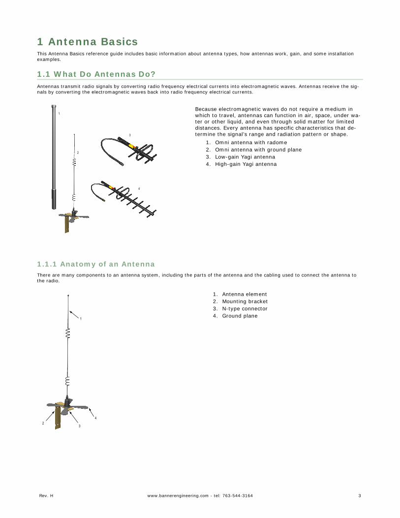
1Because electromagnetic waves do not require a medium inwhich to travel, antennas can function in air, space, under wa-ter or other liquid, and even through solid matter for limiteddistances. Every antenna has specific characteristics that de-termine the signal’s range and radiation pattern or shape.
1. Omni antenna with radome2. Omni antenna with ground plane3. Low-gain Yagi antenna4. High-gain Yagi antenna
1.1.1 Anatomy of an AntennaThere are many components to an antenna system, including the parts of the antenna and the cabling used to connect the antenna tothe radio.
1
4
32
1. Antenna element2. Mounting bracket3. N-type connector4. Ground plane
Rev. H www.bannerengineering.com - tel: 763-544-3164 3
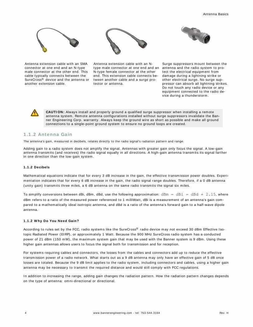
Antenna extension cable with an SMAconnector at one end and an N-typemale connector at the other end. Thiscable typically connects between theSureCross® device and the antenna oranother extension cable.
Antenna extension cable with an N-type male connector at one end and anN-type female connector at the otherend. This extension cable connects be-tween another cable and a surge pro-tector or antenna.
Surge suppressors mount between theantenna and the radio system to pro-tect the electrical equipment fromdamage during a lightning strike orother electrical surge. No surge sup-pressor can absorb all lightning strikes.Do not touch any radio device or anyequipment connected to the radio de-vice during a thunderstorm.
CAUTION: Always install and properly ground a qualified surge suppressor when installing a remoteantenna system. Remote antenna configurations installed without surge suppressors invalidate the Ban-ner Engineering Corp. warranty. Always keep the ground wire as short as possible and make all groundconnections to a single-point ground system to ensure no ground loops are created.
1.1.2 Antenna GainThe antenna’s gain, measured in decibels, relates directly to the radio signal’s radiation pattern and range.
Adding gain to a radio system does not amplify the signal. Antennas with greater gain only focus the signal. A low-gainantenna transmits (and receives) the radio signal equally in all directions. A high-gain antenna transmits its signal fartherin one direction than the low-gain system.
1.1.2 Decibels
Mathematical equations indicate that for every 3 dB increase in the gain, the effective transmission power doubles. Experi-mentation indicates that for every 6 dB increase in the gain, the radio signal range doubles. Therefore, if a 0 dB antenna(unity gain) transmits three miles, a 6 dB antenna on the same radio transmits the signal six miles.
To simplify conversions between dBi, dBm, dBd, use the following approximation: dBm = dBi = dBd + 2.15, wheredBm refers to a ratio of the measured power referenced to 1 milliWatt, dBi is a measurement of an antenna’s gain com-pared to a mathematically ideal isotropic antenna, and dBd is a ratio of the antenna’s forward gain to a half-wave dipoleantenna.
1.1.2 Why Do You Need Gain?
According to rules set by the FCC, radio systems like the SureCross® radio device may not exceed 30 dBm Effective Iso-topic Radiated Power (EIRP), or approximately 1 Watt. Because the 900 MHz SureCross radio system has a conductedpower of 21 dBm (150 mW), the maximum system gain that may be used with the Banner system is 9 dBm. Using thesehigher gain antennas allows users to focus the signal both for transmission and for reception.
For systems requiring cables and connectors, the losses from the cables and connectors add up to reduce the effectivetransmission power of a radio network. What starts out as a 9 dB antenna may only have an effective gain of 5 dB oncelosses are totaled. Because the 9 dB limit applies to the radio system, including connectors and cables, using a higher gainantenna may be necessary to transmit the required distance and would still comply with FCC regulations.
In addition to increasing the range, adding gain changes the radiation pattern. How the radiation pattern changes dependson the type of antenna: omni-directional or directional.
Antenna Basics
4 www.bannerengineering.com - tel: 763-544-3164 Rev. H
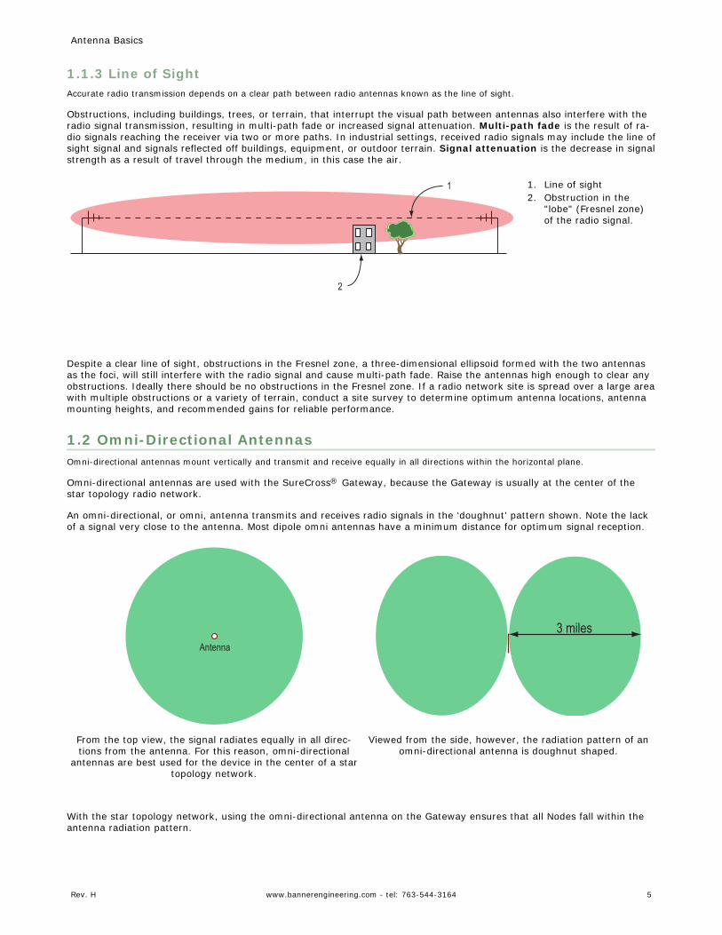
1.1.3 Line of SightAccurate radio transmission depends on a clear path between radio antennas known as the line of sight.
Obstructions, including buildings, trees, or terrain, that interrupt the visual path between antennas also interfere with theradio signal transmission, resulting in multi-path fade or increased signal attenuation. Multi-path fade is the result of ra-dio signals reaching the receiver via two or more paths. In industrial settings, received radio signals may include the line ofsight signal and signals reflected off buildings, equipment, or outdoor terrain. Signal attenuation is the decrease in signalstrength as a result of travel through the medium, in this case the air.
2
1 1. Line of sight2. Obstruction in the
"lobe" (Fresnel zone)of the radio signal.
Despite a clear line of sight, obstructions in the Fresnel zone, a three-dimensional ellipsoid formed with the two antennasas the foci, will still interfere with the radio signal and cause multi-path fade. Raise the antennas high enough to clear anyobstructions. Ideally there should be no obstructions in the Fresnel zone. If a radio network site is spread over a large areawith multiple obstructions or a variety of terrain, conduct a site survey to determine optimum antenna locations, antennamounting heights, and recommended gains for reliable performance.
1.2 Omni-Directional AntennasOmni-directional antennas mount vertically and transmit and receive equally in all directions within the horizontal plane.
Omni-directional antennas are used with the SureCross® Gateway, because the Gateway is usually at the center of thestar topology radio network.
An omni-directional, or omni, antenna transmits and receives radio signals in the ‘doughnut’ pattern shown. Note the lackof a signal very close to the antenna. Most dipole omni antennas have a minimum distance for optimum signal reception.
Antenna
3 miles
From the top view, the signal radiates equally in all direc-tions from the antenna. For this reason, omni-directional
antennas are best used for the device in the center of a startopology network.
Viewed from the side, however, the radiation pattern of anomni-directional antenna is doughnut shaped.
With the star topology network, using the omni-directional antenna on the Gateway ensures that all Nodes fall within theantenna radiation pattern.
Antenna Basics
Rev. H www.bannerengineering.com - tel: 763-544-3164 5
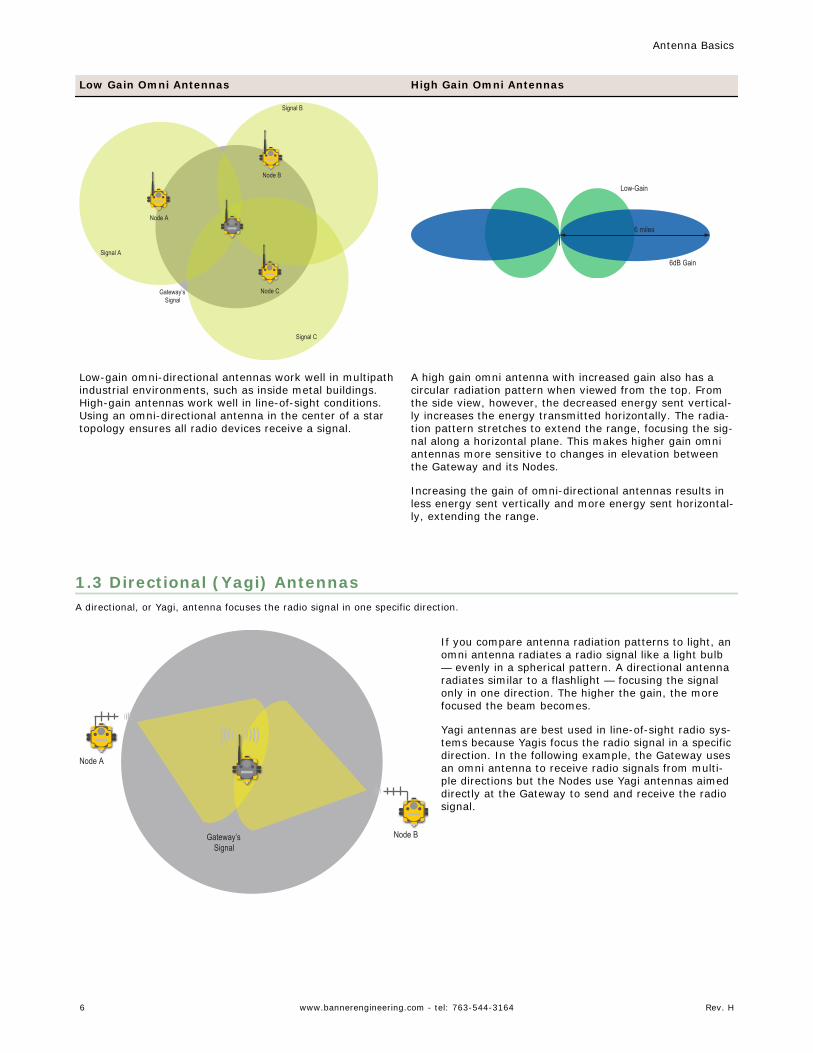
Low Gain Omni Antennas High Gain Omni Antennas
Node A
Node C
Node B
Signal A
Signal B
Signal C
Gateway’s Signal
6 miles
6dB Gain
Low-Gain
Low-gain omni-directional antennas work well in multipathindustrial environments, such as inside metal buildings.High-gain antennas work well in line-of-sight conditions.Using an omni-directional antenna in the center of a startopology ensures all radio devices receive a signal.
A high gain omni antenna with increased gain also has acircular radiation pattern when viewed from the top. Fromthe side view, however, the decreased energy sent vertical-ly increases the energy transmitted horizontally. The radia-tion pattern stretches to extend the range, focusing the sig-nal along a horizontal plane. This makes higher gain omniantennas more sensitive to changes in elevation betweenthe Gateway and its Nodes.
Increasing the gain of omni-directional antennas results inless energy sent vertically and more energy sent horizontal-ly, extending the range.
1.3 Directional (Yagi) AntennasA directional, or Yagi, antenna focuses the radio signal in one specific direction.
Node A
Node BGateway’s Signal
If you compare antenna radiation patterns to light, anomni antenna radiates a radio signal like a light bulb— evenly in a spherical pattern. A directional antennaradiates similar to a flashlight — focusing the signalonly in one direction. The higher the gain, the morefocused the beam becomes.
Yagi antennas are best used in line-of-sight radio sys-tems because Yagis focus the radio signal in a specificdirection. In the following example, the Gateway usesan omni antenna to receive radio signals from multi-ple directions but the Nodes use Yagi antennas aimeddirectly at the Gateway to send and receive the radiosignal.
Antenna Basics
6 www.bannerengineering.com - tel: 763-544-3164 Rev. H
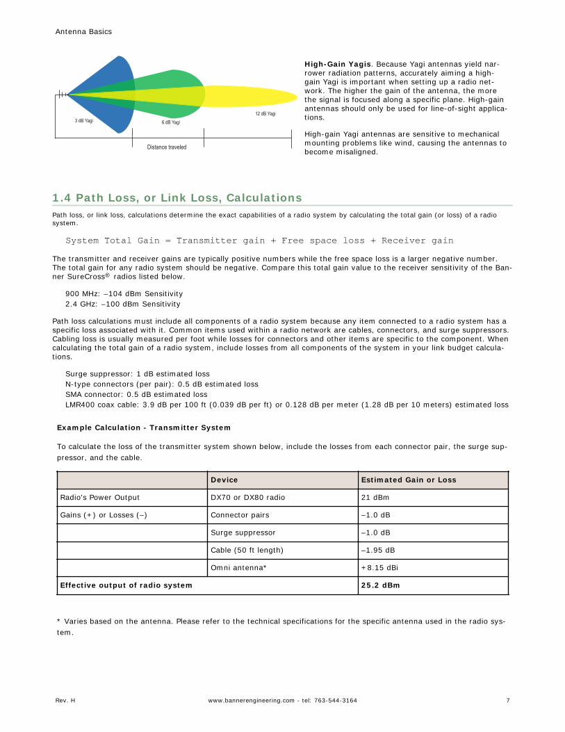
3 dB Yagi 6 dB Yagi12 dB Yagi
Distance traveled
High-Gain Yagis. Because Yagi antennas yield nar-rower radiation patterns, accurately aiming a high-gain Yagi is important when setting up a radio net-work. The higher the gain of the antenna, the morethe signal is focused along a specific plane. High-gainantennas should only be used for line-of-sight applica-tions.
High-gain Yagi antennas are sensitive to mechanicalmounting problems like wind, causing the antennas tobecome misaligned.
1.4 Path Loss, or Link Loss, CalculationsPath loss, or link loss, calculations determine the exact capabilities of a radio system by calculating the total gain (or loss) of a radiosystem.
System Total Gain = Transmitter gain + Free space loss + Receiver gainThe transmitter and receiver gains are typically positive numbers while the free space loss is a larger negative number.The total gain for any radio system should be negative. Compare this total gain value to the receiver sensitivity of the Ban-ner SureCross® radios listed below.
900 MHz: –104 dBm Sensitivity2.4 GHz: –100 dBm Sensitivity
Path loss calculations must include all components of a radio system because any item connected to a radio system has aspecific loss associated with it. Common items used within a radio network are cables, connectors, and surge suppressors.Cabling loss is usually measured per foot while losses for connectors and other items are specific to the component. Whencalculating the total gain of a radio system, include losses from all components of the system in your link budget calcula-tions.
Surge suppressor: 1 dB estimated lossN-type connectors (per pair): 0.5 dB estimated lossSMA connector: 0.5 dB estimated lossLMR400 coax cable: 3.9 dB per 100 ft (0.039 dB per ft) or 0.128 dB per meter (1.28 dB per 10 meters) estimated loss
Example Calculation - Transmitter System
To calculate the loss of the transmitter system shown below, include the losses from each connector pair, the surge sup-pressor, and the cable.
Device Estimated Gain or Loss
Radio's Power Output DX70 or DX80 radio 21 dBm
Gains (+) or Losses (–) Connector pairs –1.0 dB
Surge suppressor –1.0 dB
Cable (50 ft length) –1.95 dB
Omni antenna* +8.15 dBi
Effective output of radio system 25.2 dBm
* Varies based on the antenna. Please refer to the technical specifications for the specific antenna used in the radio sys-tem.
Antenna Basics
Rev. H www.bannerengineering.com - tel: 763-544-3164 7
3
5
1
2
4
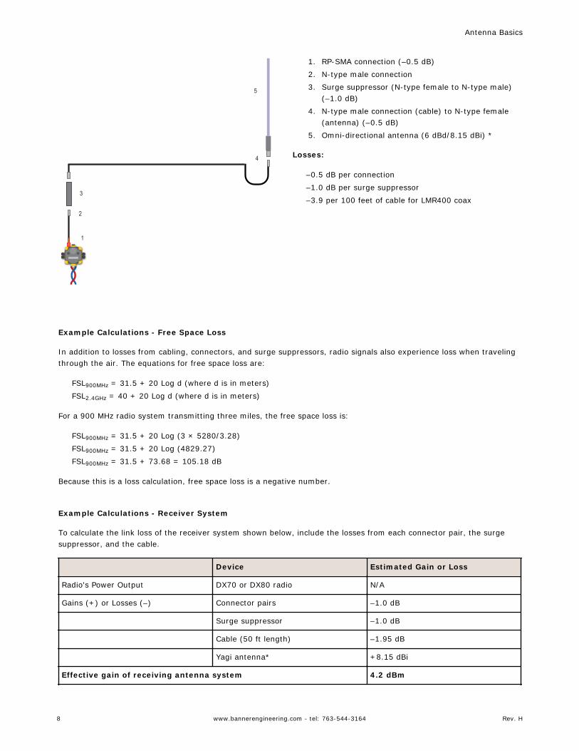
1. RP-SMA connection (–0.5 dB)2. N-type male connection3. Surge suppressor (N-type female to N-type male)
(–1.0 dB)4. N-type male connection (cable) to N-type female
(antenna) (–0.5 dB)5. Omni-directional antenna (6 dBd/8.15 dBi) *
Losses:
–0.5 dB per connection–1.0 dB per surge suppressor–3.9 per 100 feet of cable for LMR400 coax
Example Calculations - Free Space Loss
In addition to losses from cabling, connectors, and surge suppressors, radio signals also experience loss when travelingthrough the air. The equations for free space loss are:
FSL900MHz = 31.5 + 20 Log d (where d is in meters)FSL2.4GHz = 40 + 20 Log d (where d is in meters)
For a 900 MHz radio system transmitting three miles, the free space loss is:
FSL900MHz = 31.5 + 20 Log (3 × 5280/3.28)FSL900MHz = 31.5 + 20 Log (4829.27)FSL900MHz = 31.5 + 73.68 = 105.18 dB
Because this is a loss calculation, free space loss is a negative number.
Example Calculations - Receiver System
To calculate the link loss of the receiver system shown below, include the losses from each connector pair, the surgesuppressor, and the cable.
Device Estimated Gain or Loss
Radio's Power Output DX70 or DX80 radio N/A
Gains (+) or Losses (–) Connector pairs –1.0 dB
Surge suppressor –1.0 dB
Cable (50 ft length) –1.95 dB
Yagi antenna* +8.15 dBi
Effective gain of receiving antenna system 4.2 dBm
Antenna Basics
8 www.bannerengineering.com - tel: 763-544-3164 Rev. H
* Varies based on the antenna. Please refer to the technical specifications for the specific antenna used in the radio sys-tem.
3
5
1
4
2
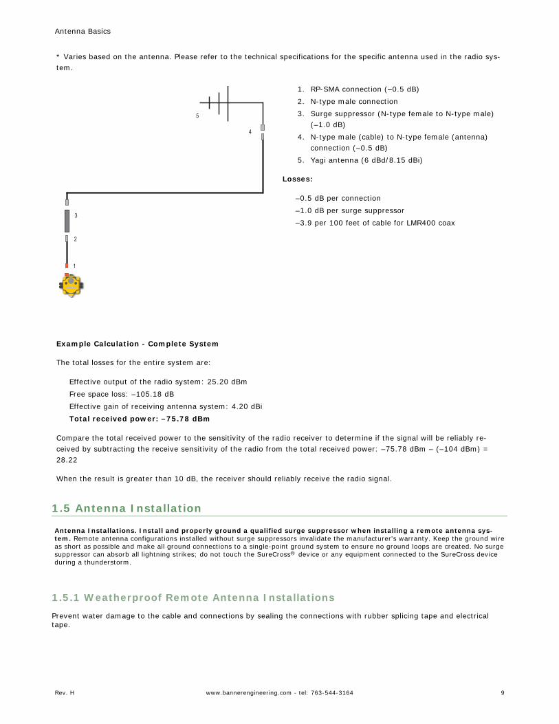
1. RP-SMA connection (–0.5 dB)2. N-type male connection3. Surge suppressor (N-type female to N-type male)
(–1.0 dB)4. N-type male (cable) to N-type female (antenna)
connection (–0.5 dB)5. Yagi antenna (6 dBd/8.15 dBi)
Losses:
–0.5 dB per connection–1.0 dB per surge suppressor–3.9 per 100 feet of cable for LMR400 coax
Example Calculation - Complete System
The total losses for the entire system are:
Effective output of the radio system: 25.20 dBmFree space loss: –105.18 dBEffective gain of receiving antenna system: 4.20 dBiTotal received power: –75.78 dBm
Compare the total received power to the sensitivity of the radio receiver to determine if the signal will be reliably re-ceived by subtracting the receive sensitivity of the radio from the total received power: –75.78 dBm – (–104 dBm) =28.22
When the result is greater than 10 dB, the receiver should reliably receive the radio signal.
1.5 Antenna Installation
Antenna Installations. Install and properly ground a qualified surge suppressor when installing a remote antenna sys-tem. Remote antenna configurations installed without surge suppressors invalidate the manufacturer's warranty. Keep the ground wireas short as possible and make all ground connections to a single-point ground system to ensure no ground loops are created. No surgesuppressor can absorb all lightning strikes; do not touch the SureCross® device or any equipment connected to the SureCross deviceduring a thunderstorm.
1.5.1 Weatherproof Remote Antenna Installations
Prevent water damage to the cable and connections by sealing the connections with rubber splicing tape and electricaltape.
Antenna Basics
Rev. H www.bannerengineering.com - tel: 763-544-3164 9
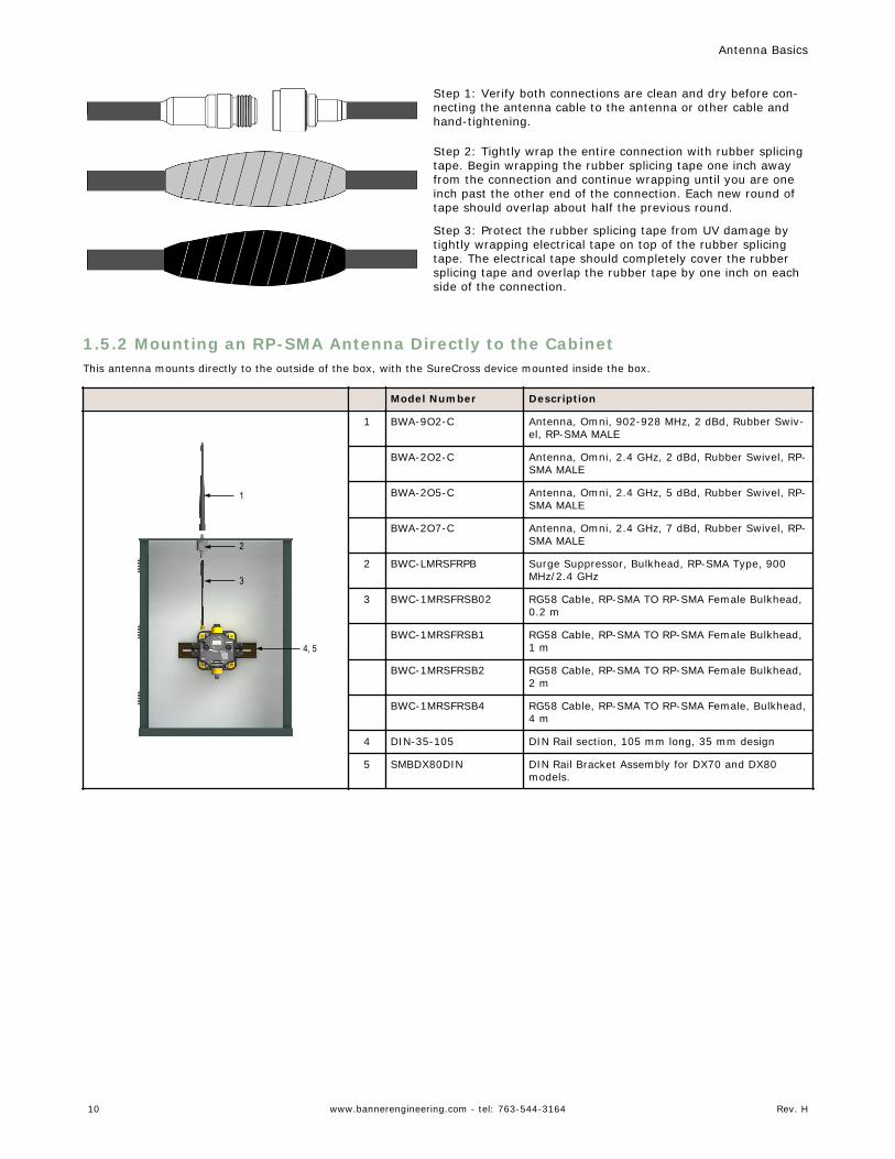
Step 1: Verify both connections are clean and dry before con-necting the antenna cable to the antenna or other cable andhand-tightening.
Step 2: Tightly wrap the entire connection with rubber splicingtape. Begin wrapping the rubber splicing tape one inch awayfrom the connection and continue wrapping until you are oneinch past the other end of the connection. Each new round oftape should overlap about half the previous round.
Step 3: Protect the rubber splicing tape from UV damage bytightly wrapping electrical tape on top of the rubber splicingtape. The electrical tape should completely cover the rubbersplicing tape and overlap the rubber tape by one inch on eachside of the connection.
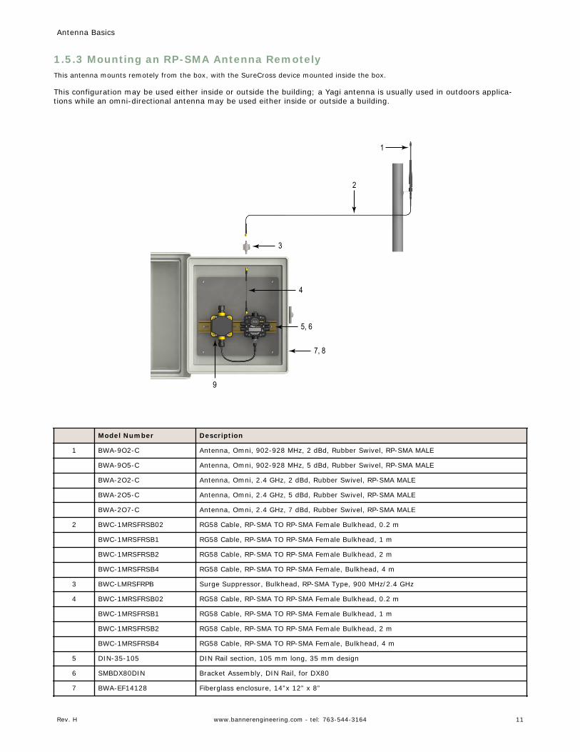
1.5.2 Mounting an RP-SMA Antenna Directly to the CabinetThis antenna mounts directly to the outside of the box, with the SureCross device mounted inside the box.
Model Number Description
1
3
4, 5
2
1 BWA-9O2-C Antenna, Omni, 902-928 MHz, 2 dBd, Rubber Swiv-el, RP-SMA MALE
BWA-2O2-C Antenna, Omni, 2.4 GHz, 2 dBd, Rubber Swivel, RP-SMA MALE
BWA-2O5-C Antenna, Omni, 2.4 GHz, 5 dBd, Rubber Swivel, RP-SMA MALE
BWA-2O7-C Antenna, Omni, 2.4 GHz, 7 dBd, Rubber Swivel, RP-SMA MALE
2 BWC-LMRSFRPB Surge Suppressor, Bulkhead, RP-SMA Type, 900MHz/2.4 GHz
3 BWC-1MRSFRSB02 RG58 Cable, RP-SMA TO RP-SMA Female Bulkhead,0.2 m
BWC-1MRSFRSB1 RG58 Cable, RP-SMA TO RP-SMA Female Bulkhead,1 m
BWC-1MRSFRSB2 RG58 Cable, RP-SMA TO RP-SMA Female Bulkhead,2 m
BWC-1MRSFRSB4 RG58 Cable, RP-SMA TO RP-SMA Female, Bulkhead,4 m
4 DIN-35-105 DIN Rail section, 105 mm long, 35 mm design
5 SMBDX80DIN DIN Rail Bracket Assembly for DX70 and DX80models.
Antenna Basics
10 www.bannerengineering.com - tel: 763-544-3164 Rev. H
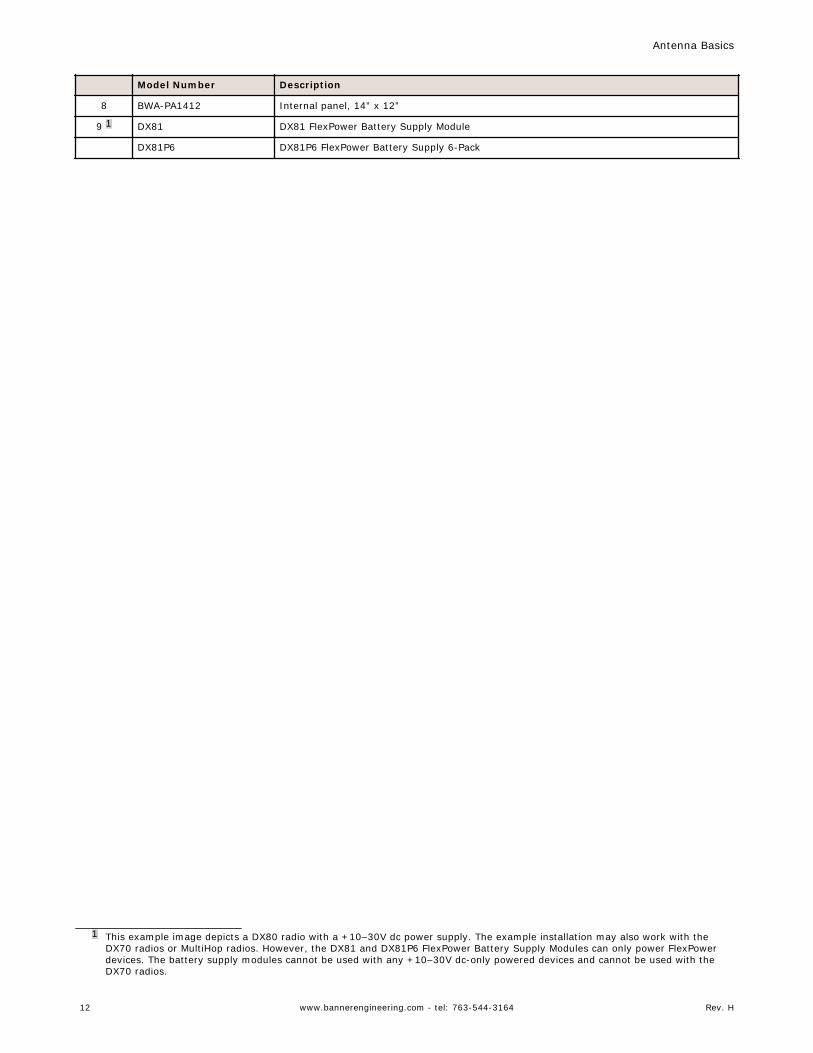
1.5.3 Mounting an RP-SMA Antenna RemotelyThis antenna mounts remotely from the box, with the SureCross device mounted inside the box.
This configuration may be used either inside or outside the building; a Yagi antenna is usually used in outdoors applica-tions while an omni-directional antenna may be used either inside or outside a building.
1
2
3
4
5, 6
7, 8
9
Model Number Description
1 BWA-9O2-C Antenna, Omni, 902-928 MHz, 2 dBd, Rubber Swivel, RP-SMA MALE
BWA-9O5-C Antenna, Omni, 902-928 MHz, 5 dBd, Rubber Swivel, RP-SMA MALE
BWA-2O2-C Antenna, Omni, 2.4 GHz, 2 dBd, Rubber Swivel, RP-SMA MALE
BWA-2O5-C Antenna, Omni, 2.4 GHz, 5 dBd, Rubber Swivel, RP-SMA MALE
BWA-2O7-C Antenna, Omni, 2.4 GHz, 7 dBd, Rubber Swivel, RP-SMA MALE
2 BWC-1MRSFRSB02 RG58 Cable, RP-SMA TO RP-SMA Female Bulkhead, 0.2 m
BWC-1MRSFRSB1 RG58 Cable, RP-SMA TO RP-SMA Female Bulkhead, 1 m
BWC-1MRSFRSB2 RG58 Cable, RP-SMA TO RP-SMA Female Bulkhead, 2 m
BWC-1MRSFRSB4 RG58 Cable, RP-SMA TO RP-SMA Female, Bulkhead, 4 m
3 BWC-LMRSFRPB Surge Suppressor, Bulkhead, RP-SMA Type, 900 MHz/2.4 GHz
4 BWC-1MRSFRSB02 RG58 Cable, RP-SMA TO RP-SMA Female Bulkhead, 0.2 m
BWC-1MRSFRSB1 RG58 Cable, RP-SMA TO RP-SMA Female Bulkhead, 1 m
BWC-1MRSFRSB2 RG58 Cable, RP-SMA TO RP-SMA Female Bulkhead, 2 m
BWC-1MRSFRSB4 RG58 Cable, RP-SMA TO RP-SMA Female, Bulkhead, 4 m
5 DIN-35-105 DIN Rail section, 105 mm long, 35 mm design
6 SMBDX80DIN Bracket Assembly, DIN Rail, for DX80
7 BWA-EF14128 Fiberglass enclosure, 14”x 12” x 8”
Antenna Basics
Rev. H www.bannerengineering.com - tel: 763-544-3164 11
Model Number Description
8 BWA-PA1412 Internal panel, 14” x 12”
9 1 DX81 DX81 FlexPower Battery Supply Module
DX81P6 DX81P6 FlexPower Battery Supply 6-Pack
1 This example image depicts a DX80 radio with a +10–30V dc power supply. The example installation may also work with theDX70 radios or MultiHop radios. However, the DX81 and DX81P6 FlexPower Battery Supply Modules can only power FlexPowerdevices. The battery supply modules cannot be used with any +10–30V dc-only powered devices and cannot be used with theDX70 radios.
Antenna Basics
12 www.bannerengineering.com - tel: 763-544-3164 Rev. H
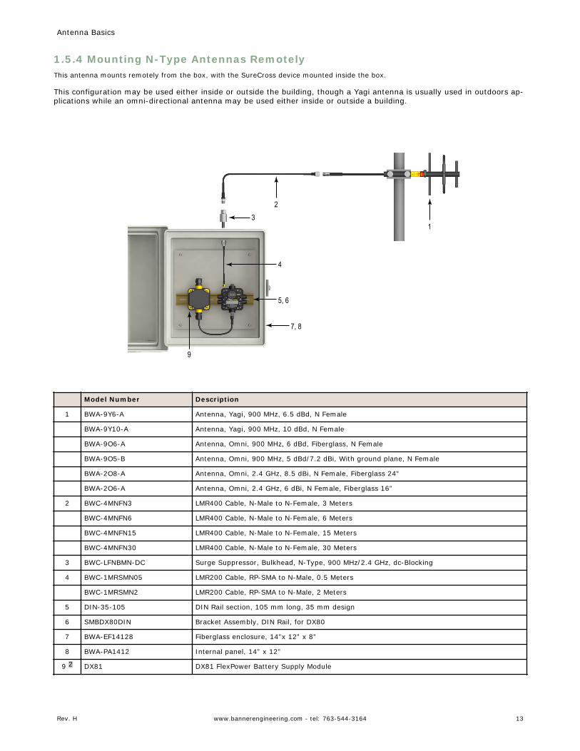
1.5.4 Mounting N-Type Antennas RemotelyThis antenna mounts remotely from the box, with the SureCross device mounted inside the box.
This configuration may be used either inside or outside the building, though a Yagi antenna is usually used in outdoors ap-plications while an omni-directional antenna may be used either inside or outside a building.
13
4
5, 6
2
7, 8
9
Model Number Description
1 BWA-9Y6-A Antenna, Yagi, 900 MHz, 6.5 dBd, N Female
BWA-9Y10-A Antenna, Yagi, 900 MHz, 10 dBd, N Female
BWA-9O6-A Antenna, Omni, 900 MHz, 6 dBd, Fiberglass, N Female
BWA-9O5-B Antenna, Omni, 900 MHz, 5 dBd/7.2 dBi, With ground plane, N Female
BWA-2O8-A Antenna, Omni, 2.4 GHz, 8.5 dBi, N Female, Fiberglass 24”
BWA-2O6-A Antenna, Omni, 2.4 GHz, 6 dBi, N Female, Fiberglass 16”
2 BWC-4MNFN3 LMR400 Cable, N-Male to N-Female, 3 Meters
BWC-4MNFN6 LMR400 Cable, N-Male to N-Female, 6 Meters
BWC-4MNFN15 LMR400 Cable, N-Male to N-Female, 15 Meters
BWC-4MNFN30 LMR400 Cable, N-Male to N-Female, 30 Meters
3 BWC-LFNBMN-DC Surge Suppressor, Bulkhead, N-Type, 900 MHz/2.4 GHz, dc-Blocking
4 BWC-1MRSMN05 LMR200 Cable, RP-SMA to N-Male, 0.5 Meters
BWC-1MRSMN2 LMR200 Cable, RP-SMA to N-Male, 2 Meters
5 DIN-35-105 DIN Rail section, 105 mm long, 35 mm design
6 SMBDX80DIN Bracket Assembly, DIN Rail, for DX80
7 BWA-EF14128 Fiberglass enclosure, 14”x 12” x 8”
8 BWA-PA1412 Internal panel, 14” x 12”
9 2 DX81 DX81 FlexPower Battery Supply Module
Antenna Basics
Rev. H www.bannerengineering.com - tel: 763-544-3164 13
Model Number Description
DX81P6 DX81P6 FlexPower Battery Supply 6-Pack
2 This example image depicts a DX80 radio with a +10–30V dc power supply. The example installation may also work with theDX70 radios or MultiHop radios. However, the DX81 and DX81P6 FlexPower Battery Supply Modules can only power FlexPowerdevices. The battery supply modules cannot be used with any +10–30V dc-only powered devices and cannot be used with theDX70 radios.
Antenna Basics
14 www.bannerengineering.com - tel: 763-544-3164 Rev. H
IndexAantenna
dipole 5direct installation 10directional 6gain 4omni 5remote installation 11–13Yagi 6
Ccable loss 4
Ddecibel 4directional antenna 6
EEffective Isotropic Radiation Power 4EIRP 4
Ffree space loss 7
Ggain 4
Llink loss 7loss
cable 4free space 7path 7system 7
Ppath loss 7
Sstar topology 5
Ttopology
star 5
Wweatherproofing 9
YYagi antenna 6