Antenna & Systems Monitoring
17
Antenna & Systems Monitoring Application Note
Transcript of Antenna & Systems Monitoring

Antenna & Systems Monitoring
Application Note
Copyright RF Industries Pty Ltd 2016. Subject to change without notice.
rfiwireless.com.au 2
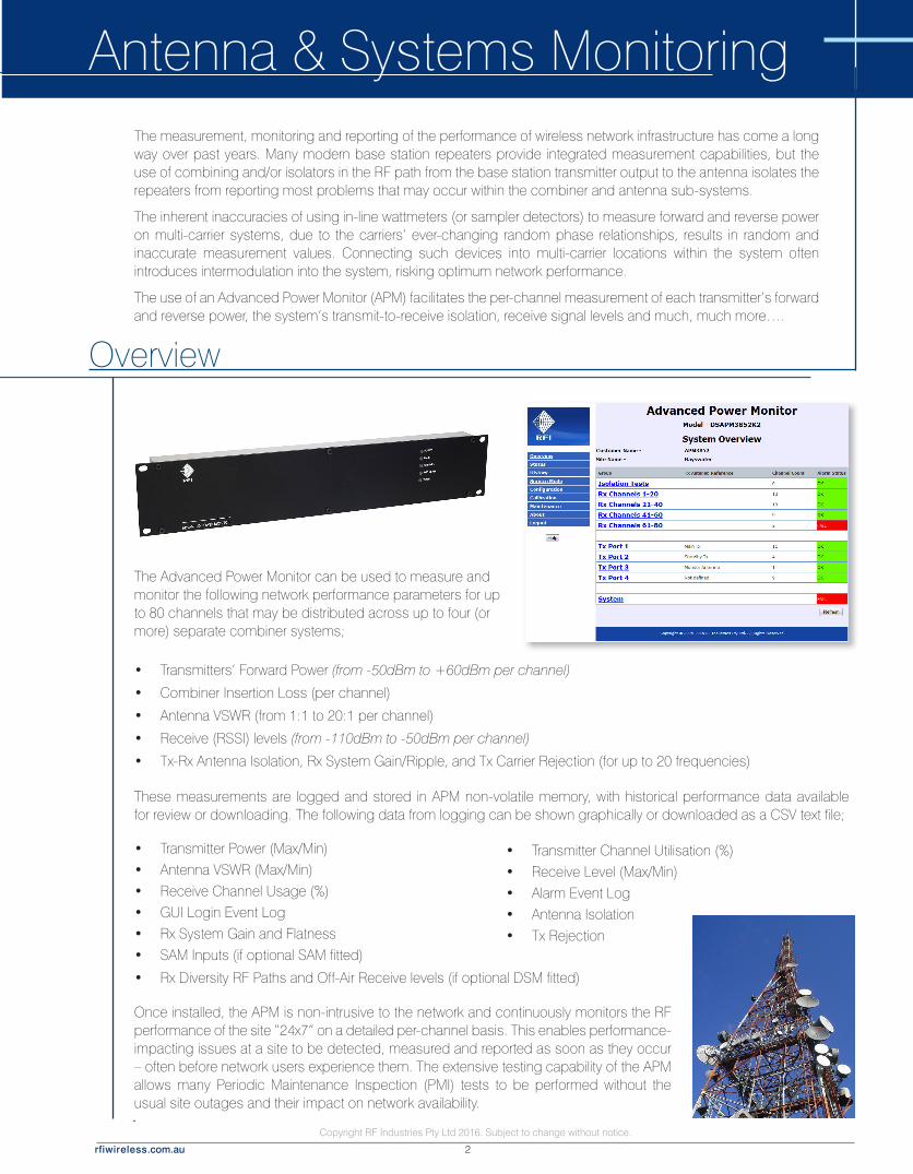
The Advanced Power Monitor can be used to measure and monitor the following network performance parameters for up to 80 channels that may be distributed across up to four (or more) separate combiner systems;
Overview
Antenna & Systems MonitoringThe measurement, monitoring and reporting of the performance of wireless network infrastructure has come a long way over past years. Many modern base station repeaters provide integrated measurement capabilities, but the use of combining and/or isolators in the RF path from the base station transmitter output to the antenna isolates the repeaters from reporting most problems that may occur within the combiner and antenna sub-systems.
The inherent inaccuracies of using in-line wattmeters (or sampler detectors) to measure forward and reverse power on multi-carrier systems, due to the carriers’ ever-changing random phase relationships, results in random and inaccurate measurement values. Connecting such devices into multi-carrier locations within the system often introduces intermodulation into the system, risking optimum network performance.
The use of an Advanced Power Monitor (APM) facilitates the per-channel measurement of each transmitter’s forward and reverse power, the system’s transmit-to-receive isolation, receive signal levels and much, much more….
Once installed, the APM is non-intrusive to the network and continuously monitors the RF performance of the site “24x7” on a detailed per-channel basis. This enables performance-impacting issues at a site to be detected, measured and reported as soon as they occur – often before network users experience them. The extensive testing capability of the APM allows many Periodic Maintenance Inspection (PMI) tests to be performed without the usual site outages and their impact on network availability.
• Transmitter Channel Utilisation (%) • Receive Level (Max/Min) • Alarm Event Log• Antenna Isolation• Tx Rejection
• Transmitter Power (Max/Min) • Antenna VSWR (Max/Min)• Receive Channel Usage (%)• GUI Login Event Log• Rx System Gain and Flatness• SAM Inputs (if optional SAM fitted)
• Rx Diversity RF Paths and Off-Air Receive levels (if optional DSM fitted)
These measurements are logged and stored in APM non-volatile memory, with historical performance data available for review or downloading. The following data from logging can be shown graphically or downloaded as a CSV text file;
• Transmitters’ Forward Power (from -50dBm to +60dBm per channel)
• Combiner Insertion Loss (per channel)
• Antenna VSWR (from 1:1 to 20:1 per channel)
• Receive (RSSI) levels (from -110dBm to -50dBm per channel)
• Tx-Rx Antenna Isolation, Rx System Gain/Ripple, and Tx Carrier Rejection (for up to 20 frequencies)

Copyright RF Industries Pty Ltd 2016. Subject to change without notice.
rfiwireless.com.au 3
Interconnection
APM System Interconnection Diagram
Up to ten (10) Site Alarm Modules (SAMs) may be connected to an APM, adding the monitoring of temperature, analogue voltages and digital inputs, in addition to providing multiple relay outputs, to enhance an APM’s functionality.
An optional Diversity Signal Monitor (DSM) may also be connected to an APM, adding the monitoring of Diversity Receive RF signal paths (as used in some digital networks), in addition to an isolated external antenna port – for enhanced off-air monitoring of signals – such as a DAS, or adjacent networks sites’ coverage propagation.
APM FRONT VIEW
Tx ANTENNA 1
COUPLER TOP VIEW - MOUNTED ON 1RU FRONT PANEL
Tx COMBINER (1)
APM REAR VIEW
APM + 1 ANTENNA LINE COUPLER
FWD
RFL
OPTIONAL DEDICATED Rx MONITORING
ANTENNA FROM SPARE PORT(S) ON
BTS Rx MUX(S)
TO ADDITIONAL COUPLERS IF REQUIRED
OPTIONAL SAM(s) or CAM(s)
1
10
to
MONITORED CHANNELS
BTS PTT LINE CONDITIONING
10 ASSIGNED ALARM RELAY OUTPUTS
4 EXT ALARM INPUTS
10 EXT ALARM INPUTS
OPTIONAL DSM
4 ASSIGNED ALARM RELAY OUTPUTS
Rx ANTENNA(s)

Copyright RF Industries Pty Ltd 2016. Subject to change without notice.
rfiwireless.com.au 4
Network Site MonitoringWhen installed at a network site, an APM can measure base station transmitter combiner output powers and antenna VSWRs, and receive levels from network terminals, remote RTUs or adjacent network sites – all on a per-channel basis. In addition, the site’s transmit-to-receive isolation, receiver antenna and feeder cable, and the receiver multicoupling system’s gain, ripple, and transmitter carrier rejection can be measured, benchmarked, and regularly retested to confirm continuing correct operation.
The programming of alarm thresholds values can be set based on network user’s coverage requirements, coverage overlap from adjoining sites, and maintenance obligations. Alarm events can notify maintenance personnel of a developing fault and, subject to the severity off the fault’s impact on network users, an appropriate response can be actioned.
For example, if an antenna VSWR alarm is configured to trigger when it reaches 1.8:1, a decision can be made on the priority of response required. If the event occurred at 2am on Saturday morning, and the site benefitted from coverage overlap from surrounding sites, a response decision might be to schedule the maintenance activity for 9am Monday morning as the level of impact may be determined as ‘minor’.
The Advanced Power Monitor is ideally suited to a wide range of applications supporting wireless networks. Its capabilities cater for analogue, digital, FDMA and TDMA networks.
The user-friendly integral APM Graphical User Interface (GUI) displays measurement values, alarm statuses, allows parameter configuration, and is compatible with computer and handheld device users. The dry-relay contacts, SNMP, SMTP (Email) and UDP Manager Messages interfaces in the APM provide a broad range of alarm notification capabilities.
When an optional Site Alarm Module (SAM) is fitted, it’s temperature, analogue, and digital inputs enhance the RF measurement capabilities of the APM, and the SAM’s multiple dry-relay outputs enable individual alarm conditions to monitored separately – or used for specific control functions. For example, the digital inputs of the SAM can be configured to provide logical ‘AND’ functionality with the APM’s Tx or Rx level measurements, allowing a range of Trunking, Voting Shelf, Tx Steering Shelf and other radio system architectures to be monitored and alarmed.
Applications
An optional Diversity Signal Monitor (DSM) can be added to an APM at any time, facilitating the monitoring, measurement and alarming of a network site utilising Receiver Dual Diversity. The DSM also features a unique “RF Peak Level Detector” capability that can measure high levels of RF that may be overloading the network’s base station receivers and degrading network performance. Alarm thresholds can be configured for these received signal level peaks so that alarms can be actioned when they occur, and these events can be measured and logged by the APM to assist fault-finding activities. The DSM also features an External Antenna Input for the enhanced monitoring of signals outside the site’s Rx Multicoupler passband(s) – such as the off-air monitoring of the coverage propagation of adjacent network sites, the monitoring of the signal propagation of a co-sited Distributed Antenna System (DAS), and much more …..
Copyright RF Industries Pty Ltd 2016. Subject to change without notice.
rfiwireless.com.au 5
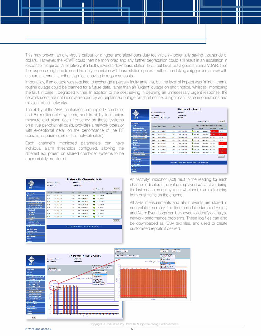
An “Activity” indicator (Act) next to the reading for each channel indicates if the value displayed was active during the last measurement cycle, or whether it is an old reading from past traffic on the channel.
All APM measurements and alarm events are stored in non-volatile memory. The time and date stamped History and Alarm Event Logs can be viewed to identify or analyze network performance problems. These log files can also be downloaded as .CSV text files, and used to create customized reports if desired.
Importantly, if an outage was required to exchange a partially faulty antenna, but the level of impact was ‘minor’, then a routine outage could be planned for a future date, rather than an ‘urgent’ outage on short notice, whilst still monitoring the fault in case it degraded further. In addition to the cost saving in delaying an unnecessary urgent response, the network users are not inconvenienced by an unplanned outage on short notice, a significant issue in operations and mission critical networks.
The ability of the APM to interface to multiple Tx combiner and Rx multicoupler systems, and its ability to monitor, measure and alarm each frequency on those systems on a true per-channel basis, provides a network operator with exceptional detail on the performance of the RF operational parameters of their network site(s).
Each channel’s monitored parameters can have individual alarm thresholds configured, allowing the different equipment on shared combiner systems to be appropriately monitored.
This may prevent an after-hours callout for a rigger and after-hours duty technician – potentially saving thousands of dollars. However, the VSWR could then be monitored and any further degradation could still result in an escalation in response if required. Alternatively, if a fault showed a “low” base station Tx output level, but a good antenna VSWR, then the response might be to send the duty technician with base station spares – rather than taking a rigger and a crew with a spare antenna – another significant saving in response costs.

Copyright RF Industries Pty Ltd 2016. Subject to change without notice.
rfiwireless.com.au 6
Network Availability (2011/12)
Available (97.1%)
Outages (2.9%)
Alarms by Type (2011/12)
Tx Alarms
Rx Alarms
Door Alarms
Fuel Alarms
OMCS & PMCS Software Integration – Manager MessagesManager Messages are short and efficient data packets that can be sent by the APM, in either UDP or TCPIP protocols, to nominated IP addresses for use by third party application software. Traffic messages are sent by the APM whenever a on/off change in the monitored Tx channel(s) occurs, and a Status message is sent whenever any change in any Alarm Status occurs. Manager Messages are configured in the APM GUI, and their use allows Traffic and Alarm Status messages from one or more APMs to be conveniently monitored by a single host (i.e. a Network Management System).
Total Alarm Hours (2011/12)
Tx Outages (234)
Rx Outages (23)
Total (257)
Low and high level alarm thresholds can be configured on most measurements, providing a comprehensive network RF testing capability to APM users. Alarms are presented on front panel LEDs, and they can also be configured to be presented via dry relay contacts, displayed in the APM’s Graphical User Interface (GUI) , retrieved or sent via SNMP, or sent as SMTP (Email) messages or UDP Traffic and Status data packets.
A comprehensive Alarm Log is also available to provide a history of alarm events. This log can also be downloaded as a CSV text file and used to create KPI reports such as the number of faults, operating duration, MTBF, or MTTR. When coupled with the History Log, this could be used to provide a series of datasets on recurring faults, unreliable equipments and related maintenance metrics.
History log files from one or more sites can be collected, collated, and presented in reports (created in Excel™ etc) to show overall network performance
The APM’s functionality provides network owners and operators with a unique and comprehensive monitoring, measurement and alarming capability that enhances their ability to maintain their network, at its optimum performance and availability levels, cost effectively.

Copyright RF Industries Pty Ltd 2016. Subject to change without notice.
rfiwireless.com.au 7
Tx Monitoring
When Monitor Tx Channel is selected and the Start button clicked, the nominated frequency is measured. This may be considered similar to a digital power meter, with both Tx Forward Power and VSWR being displayed. This capability may be used to assist base station testing or combiner tuning activities, or to monitor one channel constantly.
Rx Monitoring
When Monitor Rx Channel is selected in “Channel” mode, the nominated frequency is measured. Monitor Rx may be used for several testing purposes. It can be used to monitor the subscriber terminal inbound (or uplink) signal. This is the base station’s received signal (RSSI), and the resulting keyed Tx output is displayed as the Tx Fwd Pwr. A displayed inbound Rx level, without a corresponding Tx Fwd Pwr value, may indicate a faulty base station – or an illegal user or other interfering signal operating on the monitored Rx frequency.
When the Monitor Rx Channel is in “Frequency” mode, any frequency may be selected from the drop-down fields (or entered directly) and monitored when the Start button is clicked.
Transmitters at the site not being directly measured by the APM will usually be measurable on the APM’s Rx port at a level attenuated by the Rx system’s preselector rejection and Tx-Rx antenna isolation at the monitored Tx frequency.
This feature may be used to monitor other frequencies at the site, assisting in fault finding activities such as desense or intermodulation analysis by monitoring the level and co-incidence of other site users’ Tx or Rx activity.
In each of the Tx and Rx measurement fields the unit of measure can be selected for user convenience. When the user navigates to another GUI screen, or if the Service Mode screen has not been used for a period of time, then the normal per-channel measurement and data logging of all the APM’s programmed frequencies automatically resumes.
If the optional DSM module is fitted, the APM can display the RSSI of both RF signal paths in a dual Rx diversity system (RxA and RxB), in addition to an isolated External Rx signal path (RxE), which may be used to monitor Signals outside the site’s Rx passbands – such as the off-air monitoring of adjacent sites’ Tx frequencies, or of a co-sited Distributed Antenna System (DAS).
Service Mode The APM also provides a GUI screen called Service Mode. When this screen is being viewed, the normal per-channel measurement and data logging of all of the programmed frequencies is paused, and only the Tx and/or Rx frequency selected on this Service Mode page is monitored and measured. This allows a faster measurement refresh cycle to be provided during this focussed measurement activity.

Copyright RF Industries Pty Ltd 2016. Subject to change without notice.
rfiwireless.com.au 8
Diversity Receive MonitoringAn (optional) Diversity Signal Monitor (DSM) may be fitted to an APM to support networks using two receive antennas, such as systems using dual diversity or redundant Rx antennas.
The DSM may be added to an APM at any time – providing a network technology upgrade path as and when required.
The DSM also improves the APM’s Rx Sensitivity capability and provides an enhanced ability to monitor frequencies in other applications - such as the off-air monitoring of adjacent network sites’ coverage propagation, the monitoring of a DAS, and much more….
The DSM also features a unique “RF Peak Level Detector” capability that can measure high levels of RF, even of very short burst duration, that may be overloading the network’s base station receivers and degrading network performance. Alarm thresholds can be configured for these received signal level peaks so that alarms can be actioned when they occur, and these events are measured, logged and may be viewed in the APM GUI to assist fault-finding activities.
The DSM adds Dual Diversity (RxA, RxB) and External Antenna (RxE) configurability into the APM GUI and is selectable and configurable on a per-channel basis. Rx level measurements for all three receive paths (RxA, RxB and RxE) may now be used in the Status, System Isolation Tests and Service Mode pages of the APM GUI.
Optional Diversity Signal Monitor (DSM)

Copyright RF Industries Pty Ltd 2016. Subject to change without notice.
rfiwireless.com.au 9
Adjacent Sites-MonitoringIf an APM is installed at a dominant “high” network site, it can also be configured to ‘off-air’ monitor channels from surrounding network sites. In trunking networks, this is particularly useful for monitoring a control channel from adjacent sites.
This concept requires adequate isolation between the APM site’s Tx antenna and the off-air Rx antenna and provides basic monitoring of coverage - yet confirms the continuing operation of other sites within the network.
Adding more APMs to other sites adds more data, providing more than one signal level reading from each site – more thoroughly confirming network and coverage performance.
Multiple sites’ data can also be collected, collated and presented to identify performance impacting changes in network coverage performance.
Monitoring Co-Sited TransmittersOther site users’ transmitters, that are not combined in the Tx Combiners connected to the APM, may also be monitored by entering them as frequencies in the Rx Frequency screens of the GUI. This monitoring method allows those other frequencies to be measured and logged, providing level and activity data over time.
This is particularly useful in assisting the tracing of intermodulation mixes when other site users’ transmitters are suspected of involvement.
Suspected frequencies can be entered in spare Rx channel positions, with the Act indicator showing the simultaneous keying of monitored frequencies. The ability to assign “detection” (alarm) thresholds to these measurements allows alarm notifications to be triggered. Time and data stamped APM History logs and the ability to view this activity remotely via the GUI provides additional fault-finding capabilities to assist in the resolution of site performance issues.
Copyright RF Industries Pty Ltd 2016. Subject to change without notice.
rfiwireless.com.au 10
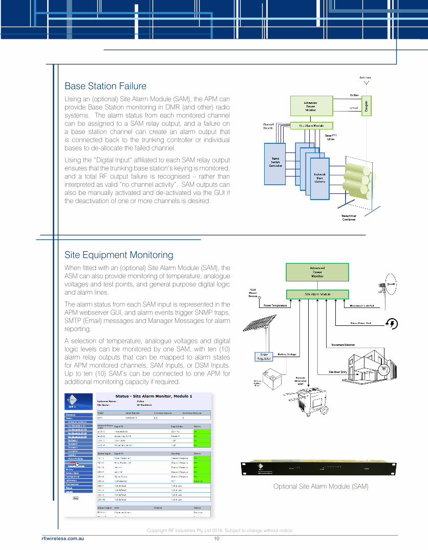
Base Station FailureUsing an (optional) Site Alarm Module (SAM), the APM can provide Base Station monitoring in DMR (and other) radio systems. The alarm status from each monitored channel can be assigned to a SAM relay output, and a failure on a base station channel can create an alarm output that is connected back to the trunking controller or individual bases to de-allocate the failed channel.
Using the “Digital Input” affiliated to each SAM relay output ensures that the trunking base station’s keying is monitored, and a total RF output failure is recognised – rather than interpreted as valid “no channel activity”. SAM outputs can also be manually activated and de-activated via the GUI if the deactivation of one or more channels is desired.
Site Equipment MonitoringWhen fitted with an (optional) Site Alarm Module (SAM), the ASM can also provide monitoring of temperature, analogue voltages and test points, and general purpose digital logic and alarm lines.
The alarm status from each SAM input is represented in the APM webserver GUI, and alarm events trigger SNMP traps, SMTP (Email) messages and Manager Messages for alarm reporting.
A selection of temperature, analogue voltages and digital logic levels can be monitored by one SAM, with ten (10) alarm relay outputs that can be mapped to alarm states for APM monitored channels, SAM Inputs, or DSM Inputs. Up to ten (10) SAM’s can be connected to one APM for additional monitoring capacity if required.
Optional Site Alarm Module (SAM)
Copyright RF Industries Pty Ltd 2016. Subject to change without notice.
rfiwireless.com.au 11
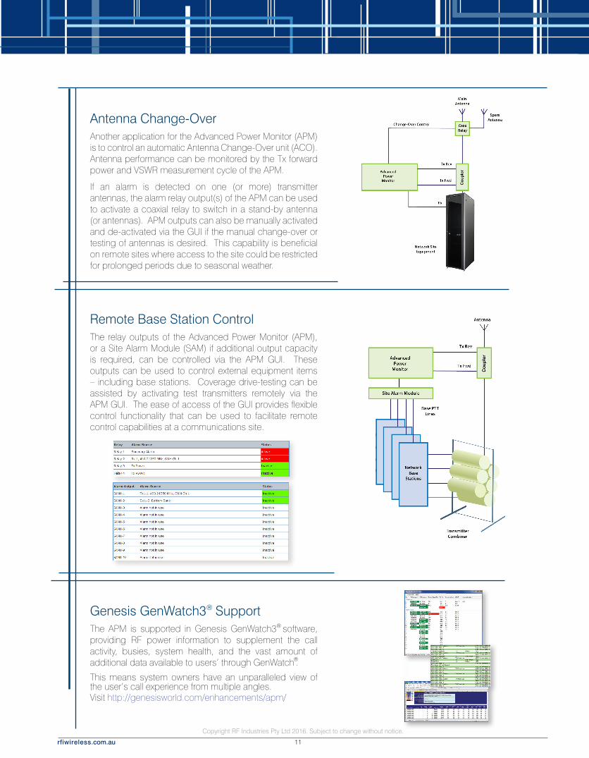
Antenna Change-OverAnother application for the Advanced Power Monitor (APM) is to control an automatic Antenna Change-Over unit (ACO). Antenna performance can be monitored by the Tx forward power and VSWR measurement cycle of the APM.
If an alarm is detected on one (or more) transmitter antennas, the alarm relay output(s) of the APM can be used to activate a coaxial relay to switch in a stand-by antenna (or antennas). APM outputs can also be manually activated and de-activated via the GUI if the manual change-over or testing of antennas is desired. This capability is beneficial on remote sites where access to the site could be restricted for prolonged periods due to seasonal weather.
Remote Base Station ControlThe relay outputs of the Advanced Power Monitor (APM), or a Site Alarm Module (SAM) if additional output capacity is required, can be controlled via the APM GUI. These outputs can be used to control external equipment items – including base stations. Coverage drive-testing can be assisted by activating test transmitters remotely via the APM GUI. The ease of access of the GUI provides flexible control functionality that can be used to facilitate remote control capabilities at a communications site.
Genesis GenWatch3 SupportThe APM is supported in Genesis GenWatch3 software, providing RF power information to supplement the call activity, busies, system health, and the vast amount of additional data available to users’ through GenWatch .
This means system owners have an unparalleled view of the user’s call experience from multiple angles.Visit http://genesisworld.com/enhancements/apm/
®
®
®

Copyright RF Industries Pty Ltd 2016. Subject to change without notice.
rfiwireless.com.au 12
Non-Intrusive Periodic Maintenance Inspections (PMIs)The Advanced Power Monitor (APM) is non-intrusive to a network once its sampling coupler is installed.
The APM measures and reports on the monitored RF performance parameters on a continuous “24x7” basis, allowing the measured values to be logged during normal network operation and without impacting its users. In addition, alarm events (when the programmable alarm thresholds are exceeded) can be reported back to a Network Operations Control Center (NOCC) or maintenance personnel via the Alarm Relays, SNMP, SMTP (Email) or Manager Messages alarm reporting.
Using the APM’s collected History and Alarm event data, in conjunction with accessing the unit and its current performance measurements “real-time” via its friendly Graphical User Interface (GUI) when required, provides the ability to measure and confirm most network RF performance parameters without a planned or unplanned network outage. In circumstances, this capability can remove (or greatly reduce) the need for regular PMIs - and their associated network outages and the impact these have on operations-critical network users.
The benefits in network maintenance cost reductions in minimising the number of visits to sites, particularly ones that are remote or that have otherwise limited access, can be significant. The availability of downloadable data that can be formatted and presented in regular reports further improves network availability, fault and mean time to repair (MTTR) monitoring and KPI measurement.
Coupled with the capability to more intuitively assess network RF performance problems and the “network-availability” effects of alarm events as they unfold, the Advanced Power Monitor (APM) provides a compelling Return-On-Investment (ROI) proposition for its inclusion in every network site build.
Distributed Antenna Systems (DAS)A Distributed Antenna System (DAS) can also be monitored using an Advanced Power Monitor. Like any antenna, the DAS can have the forward power and its VSWR performance measured – on a per-channel basis.
An ‘off-air’ antenna can also be fitted to monitor the radiated signal level from the DAS – with this level having an alarm threshold value set to detect any “coverage-impacting” drop in signal levels within the system.
Using an (optional) Site Alarm Module (SAM), the DAS head-end can also be monitored and alarmed by the APM. This monitoring could include the room or equipment door entry, equipment alarm outputs, battery temperature, battery and output voltages of the Power Supply or UPS, and any other equipment alarm outputs.
New Features, Upgrades, and DocumentationThere is an active product development roadmap for the Advanced Power Monitor. New features are available in regular firmware releases. Firmware updates can be easily uploaded (locally or remotely) to an APM. Firmware update files, SNMP MIB files, Service Bulletins and User Manuals are available in the ‘Monitoring’ products category at www.rfi-motorola.com

Copyright RF Industries Pty Ltd 2016. Subject to change without notice.
rfiwireless.com.au 13
• Allows many PMI’s to be performed non-intrusively, without a site outage impacting network users (i.e. no more scheduled network outages)
• Observe network RF performance locally, or remotely, via a user friendly webserver GUI - with SNMP, SMTP (Email), Manager Messages, and relay outputs available for alarm notifications.
• Measure and monitor the output of high power multi-carrier transmit combiners on a per-channel basis – without the limitations of in-line wattmeters and RF “samplers”
• Measure and monitor other network RF parameters (receive levels, system isolation, etc)
• Allows and Tx and Rx frequencies to be analyzed to assist in the identification of interference (IM, desense, etc), illegal carriers, frequency re-use problems and other performance impacting issues.
• Measure and monitor site alarms and equipment operating status’ using (optional) Site Alarm Module(s) using temperature, analogue and digital inputs. Map individual APM channel alarms to APM and or SAM alarm relay outputs for remote control, antenna change-over, hot/standby, and other applications.
• Measure and monitor Dual Diversity and External Receive signals using the (optional) Diversity Signal Monitor (DSM) that may be added to an APM at any time – supporting network technology upgrades.
• Store historical data for later display or download
• 24x7 non-intrusive monitoring and the setting of minimum and/or maximum alarm thresholds allows the speedy detection and notification of performance-impacting changes in the networks performance
• Configuration data (frequencies, alarm thresholds, etc) is easily entered via an integral webserver GUI, or via a Configuration File Load/Save selection.
• Allows intuitive assessment of site faults prior to despatching personnel to site
• Assists in determining the need for specialised personnel (i.e. riggers) and likely required spares (such as antennas) to be determined prior to travelling to site in response to a reported fault, minimising unnecessary maintenance costs.
• Reduces maintenance effort by enabling better analysis of the likely fault cause prior to deploying resources to site, and allows appropriate spares to be taken to site
• Allows earlier planning of network outages if required for fault rectification. Reduces ‘unplanned’ outages on short notice
• Detects the onset of fault conditions “as they occur” and often before network user’s notice the impact of the fault – allowing a faster response to be initiated and resulting in better Mean Time To Repair (MTTR) performance to be achieved
• Facilitates a more detailed assessment of the impact of the fault on network performance. Is it a minor reduction of coverage, is it on just one channel, or is it a more extensive impact on the network’s grade of service?
• Provides detailed data of ongoing network performance, faults and restorations – within the RF environment. Downloadable log files allow the importation and processing of data into spreadsheets, producing network performance, maintenance and other KPI reports.
• The APM is supported in Genesis GenWatch3® software, providing RF power information to supplement the call activity, busies, system health, and the vast amount of additional data available to users’ through GenWatch®.
Features and Benefits

Copyright RF Industries Pty Ltd 2016. Subject to change without notice.
rfiwireless.com.au 14
The Advanced Power Monitor (APM) provides channel specific forward and reflected transmitted power monitoring, Rx RSSI levels for up to 80 channels, and system isolation measurements. Four paired sets of forward and reflected Tx power measurement inputs facilitate monitoring via high power in-line couplers. The low loss Antenna Line Coupler is inserted after the Tx combiner on the antenna feeder cable. All frequencies, channel bandwidths and alarm level thresholds are software definable on a per-channel basis. A DB15 rear mounted connector provides alarm reporting outputs that can be hardwired into most alarm reporting facilities. The LED’s on the front panel of the APM allow visual confirmation of the APM’s operating and alarm status. Configuration, diagnostics and communication management is facilitated through the use of an on-board webserver GUI. Optional Site Alarm Modules (SAMs) and a Diversity Signal Monitor (DSM) may be added to enhance measurement and alarm output capabilities.
Features:n Individual channel monitoring of Tx forward and reflected power and Rx levels in multi-channel, multi-carrier systems.
n Non-intrusive 24x7 measurement, monitoring and alarm reporting of a system’s RF performance parameters.
n Capable of monitoring up to 80 channels across multiple combiner systems
n Analogue, Digital, FDMA and TDMA compatible
n Local or Remote configuration and firmware updating via RJ45 Ethernet port and integral webserver.
n APM supplied with one Antenna Line Coupler, additional couplers may be ordered separately if required.
REAR VIEW
Advanced Power Monitor APM
Frequency Range (4 separate frequency models) 132-174MHz, 380-520MHz, 746-870MHz or 870-960MHz
Maximum number of monitored channels 80
Available Tx forward power / VSWR monitoring port inputs 4 pairs
Available Rx RSSI level monitoring ports 1 (up to 3 if DSM fitted)
Rx monitoring port input range -110dBm to -50dBm (up to -125dBm if DSM fitted)
Frequency channel step size (Tx & Rx) 1.25kHz
Channel measurement bandwidths 12.5kHz and 25kHz
Max spurious or IM products -30dBm
Conducted emissions Complies with CISPR22 Part B, FCC Part 15 (15.207)
Radiated emissions Complies with CISPR22 Part B, FCC Part 15 (15.209)
RF Termination connectors N (F)
Communication interface ports 2 x rear mounted TCP/IP Ethernet ports (RJ45)
Internal alarm relay contacts output connector Rear mounted DB15 (M)
Visual alarm notification Front panel mounted LED’s
Configurable alarms Summary Fault / Tx FWD power / VSWR / RSSI & System Isolation
Alarm support GUI / Relay Output / SNMP V2c Traps / SMTP Email / UDP Packets
Power supply options 11-36VDC, 36-60VDC or 100-240VAC
DC power connector Polarised 2-pin Phoenix connector
Mounting 2RU 19” rack mounting
Dimensions 19x2x3.5” / 483x50x89mm (incl connectors)
Weight < 4.4lbs / 2kgs
Operational temperature range 14° F to 140° F / -10° C to +60° C
FRONT VIEW
For more detailed information on the APM, SAM and DSM products please refer to the User Manuals, Product Briefs, Service Bulletins, Application Notes, Firmware Updates, SNMP MIB files and other support information located at www.rfi-motorola.com.
Advanced Power Monitor132-174MHz / 380-520MHz / 746-870MHz / 870-960MHzPerformance Monitoring of FWD and RFL Tx Power, Receive RSSI and System Isolation measurementsAPM1317 / APM3852 / APM7487 / APM8796
Specifications

Copyright RF Industries Pty Ltd 2016. Subject to change without notice.
rfiwireless.com.au 15
The Site Alarm Module (SAM) is an optional module used with the Antenna System Monitor (ANM) to allocate dedicated relay outputs for up to ten (10) alarm states for ASM monitored channels, SAM Inputs, or DSM Inputs. Up to ten (10) SAMs can be easily (daisy-chained) onto one APM to increase the number of monitored channels with dedicated alarm outputs.
Site Alarm Modules (SAM) and Channel Alarm Modules (CAM) may be mixed on one APM if desired. The APM auto-detects SAM modules when they are connected, and through the GUI (Graphical User Interface) of the APM the user can configure which of the SAM outputs are assigned to respective APM monitored channels. Conditional alarm status is a feature that allows the individual base station PTT lines to be compared with the APM channel alarm status, allowing a no RF output from the base station to be recognised and raise an alarm event. Four (4) additional general purpose alarm inputs are also available on each SAM to monitor site alarms - such as temperature, battery voltages, site access doors and other site conditions. Front and rear LED’sprovide a visual indication of the status of all 10 output and 4 input alarm states.
Features:n User assigned 10-Ch alarm relay module
n Auto detected by APM when connected
n Conditional Tx PTT or Rx Unsquelch status alarm monitoring
n Compact 1RU 19” rack mountable shelf.
n Expandable to a total of 10 SAM’s (and CAMs) per APM - each monitoring up to 10 Channels.
n Latched alarm outputs for Hot/Standby base station and Auto-Change Over (ACO) antenna control
n Up to 10 user configurable Tx PTT or Rx Unsquelch activated or general purpose logic alarm inputs
n Up to 4 user configurable general purpose temperature, analogue or logic alarm inputs
n Communications interface and power daisy-chained between APM and respective SAM’s
n Front and rear alarm relay activation notification LED’s
REAR VIEW
Model Number SAM0000 or SAM0000-48
Alarm outputs 10
Alarm contact type Dry Relay N.O. / Common / N.C.
Alarm contact rating - max 50VDC 1A
Alarm inputs10 (Tx PTT by channel, Rx Unsquelch by channel, or individual general
purpose digital inputs)4 (general purpose temperature, analogue voltage or digital inputs)
Alarm inputs (refer manual for detailed explanation)
PTT or digital logic: “0” = <2.5VDC “1” = > 2.5VDC
Temperature: -67° to +257° F or -55° to +125° C
Analogue: 0VDC to +5VDC or +60VDC to -60VDC or +5VDC to -60VDC
Visual alarm notification Front and Rear panel mounted LED’s
Power Supply options (APM - daisy chained) 9-36VDC or 36-60VDC
Connectors (Note: All connectors on rear)
External Alarm inputs: 1 x Polarized 8-pin Phoenix connector
Channel Alarm Outputs: 10 x Polarized 3-pin Phoenix connector
Channel Alarm Inputs: 10 x Polarized 2-pin Phoenix connector
Power Supply: 2 x Polarized 2-pin Phoenix connector
Comms Interface: 2 x DB15 (M)
Mounting 1RU 19 Rack mounting
Dimensions W 19” x H 1.75” x D 3” / W 483 x H 45 X D 77mm
Weight < 2.2lbs / <1kg
Operational temperature range - 22° F to 140° F / - 30° C to + 60° C
FRONT VIEW
Site Alarm Module (SAM)Site Alarm Module, programmable alarm monitor.Optional dedicated alarm outputs and monitored inputs module for the APMSAM0000
Specifications

Copyright RF Industries Pty Ltd 2016. Subject to change without notice.
rfiwireless.com.au 16
The Diversity Signal Monitor (DSM) is an optional module that may be used with the Advanced Power Monitor (APM) tomonitor a dual diversity (i.e. two Rx paths) antenna system. An isolated external off-air Rx path may also be monitoredto facilitate additional APM network monitoring functionality. Peak RF input levels are independently detected, monitoredand alarmed for all RF inputs, allowing high RF signal levels that may be impacting Rx system performance to bedetected, measured, reported and alarmed - assisting in fault-finding activities. The DSM can be easily added to anAPM at any time, providing a network migration path from non-diversity to diversity technologies. When a DSM isconnected to the APM, the APM will auto-detect its presence, displaying the respective DSM configuration pages via theAPM GUI (Graphical User Interface). Rear LED’s provide a visual indication of the status of the Power, Rx Inputs’ levelsand alarms.
Features:n Dual Diversity Rx Path monitoring
n Isolated External “Off-Air” Rx Path monitoring
n Peak RF Input Levels detection, measurement and alarming
n Auto detected by APM
n Compact 1RU 19” rack mountable shelf.
n Power daisy-chained from APM
n Communications interface daisy-chained from APM
REAR VIEW
Model Number DSM0000 or DSM0000-48
Frequency Range 132 - 960MHz
Impedance 50 ohms
Return Loss (all ports) > 14dB
Maximum RF Input Level (no damage) 0 dBm
Peak Detector Response Time > 1mS
Peak Detector Alarm Threshold (GUI selectable per port) -35 to -55 dBm
Peak Detector Warning Threshold (GUI selectable per port) -40 to -65 dBm
Rx Gain (GUI selectable per Rx path) 0 to 15dB
Isolation between RF Inputs > 60 dB
Visual alarm notification Rear panel mounted LEDs
Power Supply options (APM - daisy chained) 9-36VDC or 36-60VDC
Connectors
Connection to APM N (Male)
RF In and RF Out BNC (Female)
Power Supply 2 x Polarized 2-pin Phoenix connector
Comms Interface 2 x DB15 (Male)
Dimensions W 6.7 x H 2.56 x D 5.9” / W 170 x H 65 X D 150mm (including bracket)
Weight < 2.2lbs / 1kgs
Operational temperature range -22° F to 140° F / -30° C to +60° C
DSM FITTED TO ADVANCED POWER MONITOR
Diversity Signal Monitor (DSM)2 Diversity Rx Inputs and 1 External Rx InputOptional dual diversity receive paths and external receive path monitoring module for the APMDSM0000
Specifications

Copyright RF Industries Pty Ltd 2012. Subject to change without notice.
rfiwireless.com.au PB
International Support
RFI EMEA (UK)Bicester Innovation CentreCommerce HouseTelford RoadBicester OX26 4LDUnited KingdomPhone: +44 (0) 1869 255 772
RFI Americas2023 Case Parkway NorthTwinsburg OH 44087 USAPhone: +1 330 486 0706Fax: +1 330 486 0705
RFI New ZealandPO Box 38-626Howick Auckland NZPhone: +64 9 537 2683Fax: +64 9 537 2684
RFI International Sales30 Raubers RoadBanyo, Queensland AustraliaPhone: +61 7 3621 9400Fax: +61 7 3252 5505
AN-42419-1