ANSUL RESTAURANT MODEL R-102 FIRE (STANDARD SUPPRESSION UL 300
22
FEATURES • Low pH Agent • Proven Design • Reliable Cartridge Operated • Aesthetically Appealing • UL Listed – Meets Requirements of UL 300 APPLICATION The Ansul R-102 Restaurant Fire Suppression System is an automatic, pre- engineered, fire suppression system designed to protect the following areas asso- ciated with cooking equipment; ventilating equipment including hoods, ducts, plenums, and filters; fryers; griddles and range tops; upright, natural charcoal, or chain-type broil- ers; electric, lava rock, mesquite or gas-radi- ant char-broilers and woks. The system is ideally suitable for use in restaurants, hospitals, nursing homes, hotels, schools, airports, and other similar facilities. Use of the R-102 system is limited to interior applications only. The regulated release and tank assemblies must be mounted in an area where the air temperature will not fall below 32 °F (0 °C) or exceed 130 °F (54 °C). The system must be designed and installed within the guidelines of the UL Listed Design, Installation, Recharge, and Maintenance Manual. SYSTEM DESCRIPTION The restaurant fire suppression system is a pre-engineered, wet chemical, cartridge- operated, regulated pressure type with a fixed nozzle agent distribution network. It is listed with Underwriters Laboratories, Inc. (UL). The system is capable of automatic detection and actuation and/or remote manual actua- tion. Additional equipment is available for mechanical or electrical gas line shut-off applications. RESTAURANT FIRE SUPPRESSION SYSTEMS DATA SHEET MODEL R-102 (STANDARD UL 300 LISTED) The detection portion of the fire suppression system allows for automatic detection by means of specific alloy rated fusible links, which, when the temperature exceeds the rating of the link, the link separates, allowing the regulated release to actuate. A system owner’s guide is available contain- ing basic information pertaining to system operation and maintenance. A detailed tech- nical manual is also available including sys- tem description, design, installation, recharge, and maintenance procedures, plus additional equipment installation and reset- ting instructions. The system is installed and serviced by authorized distributors that are trained by the manufacturer. The basic system consists of an ANSUL AUTOMAN regulated release assembly which includes a regulated release mecha- nism and a wet chemical storage tank housed within a single enclosure. Nozzle blow-off caps, detectors, cartridges, agent, fusible links, and pulley elbows are supplied in separate packages in the quantities need- ed for fire suppression system arrangements. Additional equipment includes remote manu- al pull station, mechanical and electrical gas valves, pressure switches, and electrical switches for automatic equipment and gas line shut-off. Accessories can be added such as alarms, warning lights, etc., to installations where required. Tanks can be used in multiple arrangements to allow for larger hazard coverage. Each tank is limited to a listed maximum amount of flow numbers. ANSUL® 004212
Transcript of ANSUL RESTAURANT MODEL R-102 FIRE (STANDARD SUPPRESSION UL 300

FEATURES
• Low pH Agent
• Proven Design
• Reliable Cartridge Operated
• Aesthetically Appealing
• UL Listed – Meets Requirements of UL 300
APPLICATION
The Ansul R-102 Restaurant FireSuppression System is an automatic, pre-engineered, fire suppression systemdesigned to protect the following areas asso-ciated with cooking equipment; ventilatingequipment including hoods, ducts, plenums,and filters; fryers; griddles and range tops;upright, natural charcoal, or chain-type broil-ers; electric, lava rock, mesquite or gas-radi-ant char-broilers and woks.
The system is ideally suitable for use inrestaurants, hospitals, nursing homes, hotels,schools, airports, and other similar facilities.
Use of the R-102 system is limited to interiorapplications only. The regulated release andtank assemblies must be mounted in an areawhere the air temperature will not fall below32 °F (0 °C) or exceed 130 °F (54 °C). Thesystem must be designed and installed withinthe guidelines of the UL Listed Design,Installation, Recharge, and MaintenanceManual.
SYSTEM DESCRIPTION
The restaurant fire suppression system is apre-engineered, wet chemical, cartridge-operated, regulated pressure type with afixed nozzle agent distribution network. It islisted with Underwriters Laboratories, Inc.(UL).
The system is capable of automatic detectionand actuation and/or remote manual actua-tion. Additional equipment is available formechanical or electrical gas line shut-offapplications.
RESTAURANTFIRE SUPPRESSIONSYSTEMSDATA SHEET
MODEL R-102(STANDARDUL 300 LISTED)
The detection portion of the fire suppressionsystem allows for automatic detection bymeans of specific alloy rated fusible links,which, when the temperature exceeds therating of the link, the link separates, allowingthe regulated release to actuate.
A system owner’s guide is available contain-ing basic information pertaining to systemoperation and maintenance. A detailed tech-nical manual is also available including sys-tem description, design, installation,recharge, and maintenance procedures, plusadditional equipment installation and reset-ting instructions.
The system is installed and serviced byauthorized distributors that are trained by themanufacturer.
The basic system consists of an ANSULAUTOMAN regulated release assemblywhich includes a regulated release mecha-nism and a wet chemical storage tank
housed within a single enclosure. Nozzleblow-off caps, detectors, cartridges, agent,fusible links, and pulley elbows are suppliedin separate packages in the quantities need-ed for fire suppression system arrangements.
Additional equipment includes remote manu-al pull station, mechanical and electrical gasvalves, pressure switches, and electricalswitches for automatic equipment and gasline shut-off. Accessories can be added suchas alarms, warning lights, etc., to installationswhere required.
Tanks can be used in multiple arrangementsto allow for larger hazard coverage. Eachtank is limited to a listed maximum amount offlow numbers.
ANSUL®
004212

contains a bursting disc seal which preventsthe siphoning of agent up the pipe duringextreme temperature variations.
Regulated Release Mechanism – The regu-lated release mechanism is a spring-loaded,mechanical/pneumatic type capable of providing the expellant gas supply to one ortwo agent tanks, depending on the capacityof the gas cartridge used. It contains a facto-ry installed regulator deadset at 100 psi (6.9 bar) with an internal relief of approxi-mately 145 psi (10.0 bar). It has automaticactuation capabilities by a fusible link detec-tion system and remote manual actuation bya mechanical pull station.
The regulated release mechanism contains arelease assembly, regulator, expellant gashose, and agent storage tank housed in astainless steel enclosure with cover. Theenclosure contains knock-outs for 1/2 in.conduit. The cover contains an opening for avisual status indicator.
COMPONENT DESCRIPTION
Wet Chemical Agent – The extinguishingagent is a mixture of organic and inorganicsalts designed for rapid flame knockdownand foam securement of grease related fires.It is available in plastic containers withinstructions for wet chemical handling andusage.
Agent Tank – The agent tank is installed ina stainless steel enclosure or wall bracket.The tank is deep drawn carbon steel finishedin red enamel.
Tanks are available in two sizes: 1.5 gallon(5.7 L) and 3.0 gallon (11.4 L). The tankshave a working pressure of 100 psi (6.9 bar),a test pressure of 300 psi (20.7 bar), and aminimum burst pressure of 600 psi (41.4 bar).
The tank includes an adaptor/tube assembly.The adaptor is chrome-plated steel with a1/4 in. NPT female gas inlet and a 3/8 in.NPT female agent outlet. The adaptor also
It is compatible with mechanical gas shut-offdevices; or, when equipped with a field orfactory-installed switch, it is compatible withelectric gas line or appliance shut-offdevices.
Regulated Actuator Assembly – Whenmore than two agent tanks are required, theregulated actuator is available to provideexpellant gas for additional tanks. It is con-nected to the cartridge receiver outlet of theregulated release mechanism providingsimultaneous agent discharge. It contains aregulated actuator deadset at 100 psi (6.9 bar) with an internal relief of approxi-mately 145 psi (10.0 bar).The regulated actu-ator assembly contains a regulated actuator,regulator, expellant gas hose, and agent tankhoused in a stainless steel enclosure withcover. The enclosure contains knockouts topermit installation of the expellant gas line.
Discharge Nozzles – Each discharge nozzleis tested and listed with the R-102 system fora specific application. Nozzle tips arestamped with the flow number designation(1/2, 1, 2, and 3). Each nozzle must have ametal or rubber blow-off cap to keep the noz-zle tip orifice free of cooking grease build-up.
APPROVALS
Applicable Standards: ULI listed under EX-3470; ULC listed under CEX-747; meetsrequirements of NFPA 96 (Standard for theInstallation of Equipment for the Removalof Smoke and Grease-Laden Vapors fromCommercial Cooking Equipment); NFPA 17A(Standard on Wet Chemical ExtinguishingSystems).
ORDERING INFORMATION
Order all system components through your local authorized Ansul Distributor.
SPECIFICATIONS
An Ansul R-102 Fire Suppression System shall be furnished. The system shall be capable of protecting all hazard areas associated with cooking equipment.
1.0 GENERAL 1.1 References
1.1.1 Underwriters Laboratories, Inc. (UL)1.1.1.1 UL Standard 12541.1.1.2 UL Standard 300
1.1.2 National Fire Protection Association (NFPA)1.1.2.1 NFPA 961.1.2.2 NFPA 17A
1.2 Submittals
1.2.1 Submit two sets of manufacturer’s data sheets1.2.2 Submit two sets of piping design drawings
1.3 System Description
1.3.1 The system shall be an automatic fire suppression system using a wet chemical agent for grease relatedfires.
1.3.2 The system shall be capable of suppressing fires in the following areas associated with cooking equipment:ventilating equipment including hoods, ducts, plenums, and filters; fryers; griddles and range tops; upright,natural charcoal, or chain-type broilers; electric, lava rock, mesquite or gas-radiant char-broilers.
1.3.3 The system shall be the pre-engineered type having minimum and maximum guidelines established by themanufacturer and listed by Underwriters Laboratories, Inc. (UL).
1.3.4 The system shall be installed and serviced by personnel trained by the manufacturer.
1.4 Quality Control
1.4.1 Manufacturer: The R-102 Restaurant Fire Suppression System shall be manufactured by a company with atleast thirty years experience in the design and manufacture of pre-engineered fire suppression systems.The manufacturer shall be ISO 9002 registered.
1.4.2 Certificates: The wet agent shall be a specially formulated, aqueous solution of organic salts with a pHrange between 7.8 – 8.2, designed for flame knockdown and foam securement of grease-related fires.
1.5 Warranty, Disclaimer, and Limitations
1.5.1 The pre-engineered restaurant fire suppression system components shall be warranted for five years fromdate of delivery against defects in workmanship and material.
004214004213
1.6 Delivery
1.6.1 Packaging: All system components shall be securely packaged to provide protection during shipment.
1.7 Environmental Conditions
1.7.1 The R-102 system shall be capable of operating in a temperature range of 32 °F to 130 °F (0 °C to 54 °C).
2.0 PRODUCT 2.1 Manufacturer
2.1.1 Ansul Fire Protection, One Stanton Street, Marinette, Wisconsin 54143-2542, Telephone (715) 735-7411.
2.2 Components
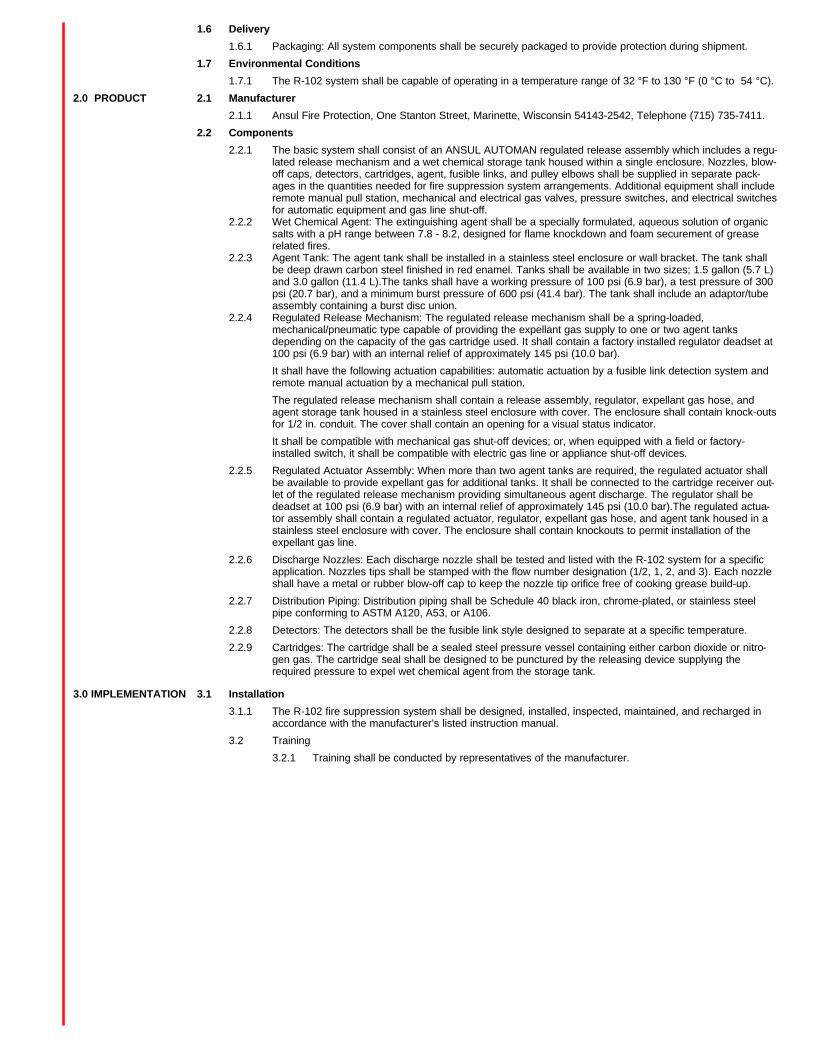
2.2.1 The basic system shall consist of an ANSUL AUTOMAN regulated release assembly which includes a regu-lated release mechanism and a wet chemical storage tank housed within a single enclosure. Nozzles, blow-off caps, detectors, cartridges, agent, fusible links, and pulley elbows shall be supplied in separate pack-ages in the quantities needed for fire suppression system arrangements. Additional equipment shall includeremote manual pull station, mechanical and electrical gas valves, pressure switches, and electrical switchesfor automatic equipment and gas line shut-off.
2.2.2 Wet Chemical Agent: The extinguishing agent shall be a specially formulated, aqueous solution of organicsalts with a pH range between 7.8 - 8.2, designed for flame knockdown and foam securement of greaserelated fires.
2.2.3 Agent Tank: The agent tank shall be installed in a stainless steel enclosure or wall bracket. The tank shallbe deep drawn carbon steel finished in red enamel. Tanks shall be available in two sizes; 1.5 gallon (5.7 L)and 3.0 gallon (11.4 L).The tanks shall have a working pressure of 100 psi (6.9 bar), a test pressure of 300psi (20.7 bar), and a minimum burst pressure of 600 psi (41.4 bar). The tank shall include an adaptor/tubeassembly containing a burst disc union.
2.2.4 Regulated Release Mechanism: The regulated release mechanism shall be a spring-loaded,mechanical/pneumatic type capable of providing the expellant gas supply to one or two agent tanksdepending on the capacity of the gas cartridge used. It shall contain a factory installed regulator deadset at100 psi (6.9 bar) with an internal relief of approximately 145 psi (10.0 bar).
It shall have the following actuation capabilities: automatic actuation by a fusible link detection system andremote manual actuation by a mechanical pull station.
The regulated release mechanism shall contain a release assembly, regulator, expellant gas hose, andagent storage tank housed in a stainless steel enclosure with cover. The enclosure shall contain knock-outsfor 1/2 in. conduit. The cover shall contain an opening for a visual status indicator.
It shall be compatible with mechanical gas shut-off devices; or, when equipped with a field or factory-installed switch, it shall be compatible with electric gas line or appliance shut-off devices.
2.2.5 Regulated Actuator Assembly: When more than two agent tanks are required, the regulated actuator shallbe available to provide expellant gas for additional tanks. It shall be connected to the cartridge receiver out-let of the regulated release mechanism providing simultaneous agent discharge. The regulator shall bedeadset at 100 psi (6.9 bar) with an internal relief of approximately 145 psi (10.0 bar).The regulated actua-tor assembly shall contain a regulated actuator, regulator, expellant gas hose, and agent tank housed in astainless steel enclosure with cover. The enclosure shall contain knockouts to permit installation of theexpellant gas line.
2.2.6 Discharge Nozzles: Each discharge nozzle shall be tested and listed with the R-102 system for a specificapplication. Nozzles tips shall be stamped with the flow number designation (1/2, 1, 2, and 3). Each nozzleshall have a metal or rubber blow-off cap to keep the nozzle tip orifice free of cooking grease build-up.
2.2.7 Distribution Piping: Distribution piping shall be Schedule 40 black iron, chrome-plated, or stainless steelpipe conforming to ASTM A120, A53, or A106.
2.2.8 Detectors: The detectors shall be the fusible link style designed to separate at a specific temperature.
2.2.9 Cartridges: The cartridge shall be a sealed steel pressure vessel containing either carbon dioxide or nitro-gen gas. The cartridge seal shall be designed to be punctured by the releasing device supplying therequired pressure to expel wet chemical agent from the storage tank.
3.0 IMPLEMENTATION 3.1 Installation
3.1.1 The R-102 fire suppression system shall be designed, installed, inspected, maintained, and recharged inaccordance with the manufacturer’s listed instruction manual.
3.2 Training
3.2.1 Training shall be conducted by representatives of the manufacturer.

ANSUL INCORPORATED, ONE STANTON STREET, MARINETTE, WI 54143-2542 715-735-7411 Form No. F-9501-1 ©1996 Ansul Incorporated Litho in U.S.A.

FEATURES
• Fast Flame Knock-Down and Securementof Grease-Related Fires
• Provides a Cooling Effect Which FurtherEnhances Its Ability to Prevent Reflash
• Designed for a Wide Variety of RestaurantHazards
• Listed by Underwriters Laboratories, Inc.(UL) as Part of the R-102 RestaurantSystem
• Ease of Recharge and Post-Fire Cleanup
• Non-Corrosive
APPLICATION
ANSULEX Low pH Liquid Fire Suppressantis designed for use only in Ansul R-102restaurant fire suppression systems. This‘‘liquid’’ agent will combat grease-relatedfires as found in restaurant appliances andventilating equipment. It should not be usedfor fires involving energized electrical haz-ards.
DESCRIPTION
ANSULEX Low pH Liquid Fire Suppressantis a specially-formulated, aqueous solutionof organic salts. The agent is pre-mixed,eliminating the need for dilution before sys-tem charging. When used as an extinguish-ing agent, it will produce no toxic by-prod-ucts.
AGENT PROPERTIES
Appearance . . . . . . . . . . . Color-CodedFluorescentYellow-Green
Storage Life . . . . . . . . . . . 12 Years
Refractive Index. . . . . . . . 1.4040
Freeze Point . . . . . . . . . . –40 °F (–40 °C)
Boiling Point. . . . . . . . . . . 230 °F (110 °C)
Specific Gravity . . . . . . . . 1.32
Kinematic Viscosity . . . . . 5.26 centistokes
pH . . . . . . . . . . . . . . . . . . 7.8 – 8.2
WARNING: Care should be taken whenhandling the agent. If contact ismade with the eyes or skin,flush with water. If the agent isswallowed, dilute with water ormilk and contact a physician.
EXTINGUISHINGAGENTDATA SHEET
ANSULEXTM LOW pHLIQUID FIRESUPPRESSANT
ANSUL®
ANSUL FIRE PROTECTIONMARINETTE, WI 54143-2542 Form No. F-9140 ©1999 Ansul Incorporated Litho in U.S.A.
APPROVALS AND LISTINGS
ANSULEX Low pH Liquid Fire Suppressanthas been tested, and is listed withUnderwriters Laboratories, Inc. (EX-3470) aspart of the Ansul R-102 Restaurant FireSuppression System.
ORDERING INFORMATION
ANSULEX Low pH Liquid Fire Suppressantis available in sealed containers.
Part No. 79694 1.5 gallon (5.7 L) Part No. 79372 3.0 gallon (11.4 L)
Recharge services are available from Ansul-authorized distributors.
ANSUL is a registered trademark and ANSULEX is a trademark.
PERFORMANCE
When used in the Ansul R-102 restaurantsystem, ANSULEX Low pH Liquid FireSuppressant is extremely effective on fires inrestaurant ventilating equipment – hoods andductwork, as well as in a variety of cookingappliances – deep-fat fryers, griddles, rangetops, and several types of broilers and char-broilers.
As the agent is sprayed in fine droplets(atomized) onto an appliance grease fire, itprovides excellent flame knock-down, sur-face-cooling, and fire-securing capabilities.When the agent reacts with the hot grease, itforms a layer of foam on the surface of thefat. This soap-like blanket of foam acts as aninsulator between the hot grease and theatmosphere, helping to prevent flammablevapors from escaping and reducing thechance for flame reignition.
Post-fire cleanup can be readily accom-plished by flushing the area with water orsteam.
Because of the composition of ANSULEXLow pH Liquid Fire Suppressant, it is com-patible with metals commonly found inrestaurant kitchen environments (i.e., stain-less steel, aluminum, galvanized metal, mildsteel, copper and brass).
FEATURES
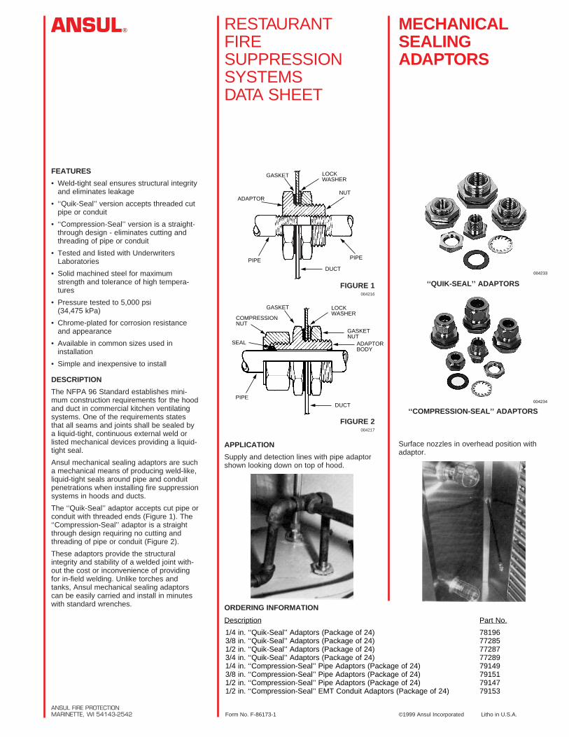
• Weld-tight seal ensures structural integrityand eliminates leakage
• ‘‘Quik-Seal’’ version accepts threaded cutpipe or conduit
• ‘‘Compression-Seal’’ version is a straight-through design - eliminates cutting andthreading of pipe or conduit
• Tested and listed with UnderwritersLaboratories
• Solid machined steel for maximumstrength and tolerance of high tempera-tures
• Pressure tested to 5,000 psi(34,475 kPa)
• Chrome-plated for corrosion resistanceand appearance
• Available in common sizes used in installation
• Simple and inexpensive to install
DESCRIPTION
The NFPA 96 Standard establishes mini-mum construction requirements for the hoodand duct in commercial kitchen ventilatingsystems. One of the requirements statesthat all seams and joints shall be sealed bya liquid-tight, continuous external weld orlisted mechanical devices providing a liquid-tight seal.
Ansul mechanical sealing adaptors are sucha mechanical means of producing weld-like,liquid-tight seals around pipe and conduitpenetrations when installing fire suppressionsystems in hoods and ducts.
The ‘‘Quik-Seal’’ adaptor accepts cut pipe orconduit with threaded ends (Figure 1). The‘‘Compression-Seal’’ adaptor is a straightthrough design requiring no cutting andthreading of pipe or conduit (Figure 2).
These adaptors provide the structuralintegrity and stability of a welded joint with-out the cost or inconvenience of providingfor in-field welding. Unlike torches andtanks, Ansul mechanical sealing adaptorscan be easily carried and install in minuteswith standard wrenches.
RESTAURANTFIRESUPPRESSIONSYSTEMSDATA SHEET
MECHANICALSEALINGADAPTORS
ANSUL®
ANSUL FIRE PROTECTIONMARINETTE, WI 54143-2542 Form No. F-86173-1 ©1999 Ansul Incorporated Litho in U.S.A.
‘‘QUIK-SEAL’’ ADAPTORS
‘‘COMPRESSION-SEAL’’ ADAPTORS
Surface nozzles in overhead position withadaptor.
FIGURE 1004216
FIGURE 2004217
APPLICATION
Supply and detection lines with pipe adaptorshown looking down on top of hood.
ORDERING INFORMATION
LOCKWASHER
NUT
PIPE
DUCT
PIPE
ADAPTOR
GASKET
LOCKWASHER
GASKETNUT
ADAPTORBODY
DUCTPIPE
SEAL
COMPRESSIONNUT
GASKET
Description Part No.
1/4 in. ‘‘Quik-Seal’’ Adaptors (Package of 24) 781963/8 in. ‘‘Quik-Seal’’ Adaptors (Package of 24) 772851/2 in. ‘‘Quik-Seal’’ Adaptors (Package of 24) 772873/4 in. ‘‘Quik-Seal’’ Adaptors (Package of 24) 772891/4 in. ‘‘Compression-Seal’’ Pipe Adaptors (Package of 24) 791493/8 in. ‘‘Compression-Seal’’ Pipe Adaptors (Package of 24) 791511/2 in. ‘‘Compression-Seal’’ Pipe Adaptors (Package of 24) 791471/2 in. ‘‘Compression-Seal’’ EMT Conduit Adaptors (Package of 24) 79153
004233
004234

ANSUL® OWNER’S GUIDERESTAURANT FIRE SUPPRESSION SYSTEM
The National Fire Protection Association (NFPA) recom-mends that employees be instructed in personal safety andthe operation of the system. Ansul provides this owner'sguide with each Restaurant Fire Suppression System.
This owner's guide has been provided to help you under-stand..........how your restaurant system works......your responsibilities for maintenance......what to do in case of fire
This owner's guide is not intended to cover all requirementsdetailed in the Installation, Operation, Recharge,Inspection, and Maintenance Manual, Part No. 418087.This guide is solely for the use of the end-user to becomemore knowledgeable with the fire suppression system andthe steps necessary in the event of a fire.
Should the end-user want to find out more information con-cerning the Ansul Restaurant Fire Suppression System,your authorized Ansul distributor can furnish a detailedInstallation, Operation, Recharge, Inspection, andMaintenance Manual.
YOUR ROLE IN FIRE PROTECTION
Your Ansul Fire Suppression System is of the highestquality. It has been carefully engineered to be reliable, man-ufactured to exacting standards, proven by over 30 years ofservice, and custom designed to protect your particularhazard.
If properly maintained, your system should provide years ofprotection. However, the primary objective of this guide is toprovide enough basic information to help you to prevent adisastrous fire. By observing some fundamental rules, youcan greatly reduce the risk of serious fire damage.
1. Keep all kitchen equipment free of grease build-up.
2. Never use flammable solvents or cleaners. Flammableresidues could be left in the hazard area.
3. Operate your exhaust system whenever the applianceis pre-heating, heating, cooking or cooling. This helps toprevent excessive heat build-up which could actuate thesystem.
4. Never operate filter-equipped exhaust systems withoutthe filters in place. Excessive grease may build-up in thehood and duct system. Use only U.L. listed filters.
5. Never restrict air intake passages; this can reduce theefficiency of your exhaust system.
6. Operate all UL tested grease extractors by the manufac-turer's instructions to ensure effective grease removalfrom the hood and duct system.
7. Never tamper with the system components (i.e.,detectors, nozzles, agent storage container(s) orreleasing unit(s).
8. Before you revise your kitchen equipment layout ormake changes which affect the basic configuration ofthe protected area, contact your trained, authorizedAnsul distributor for a system update evaluation. Thesystem is made up of components tested within limita-tions contained in the detailed installation manual. Thesystem designer must be consulted whenever changesare planned for the system or area of protection.
9. Do not allow anyone except an authorized Ansul dis-tributor to perform maintenance on your Ansul system.Maintenance to your system must be performed semi-annually. It is essential that the system be maintainedproperly.
10. Post operating instructions in an obvious place in thekitchen and make sure your employees know what to doin case of fire.
11. Make certain that hand portable extinguishers areproperly placed and compatible with the restaurantsystem. An authorized Ansul distributor can assist yourneeds.
1
OWNER’S GUIDERESTAURANT FIRE SUPPRESSION SYSTEM
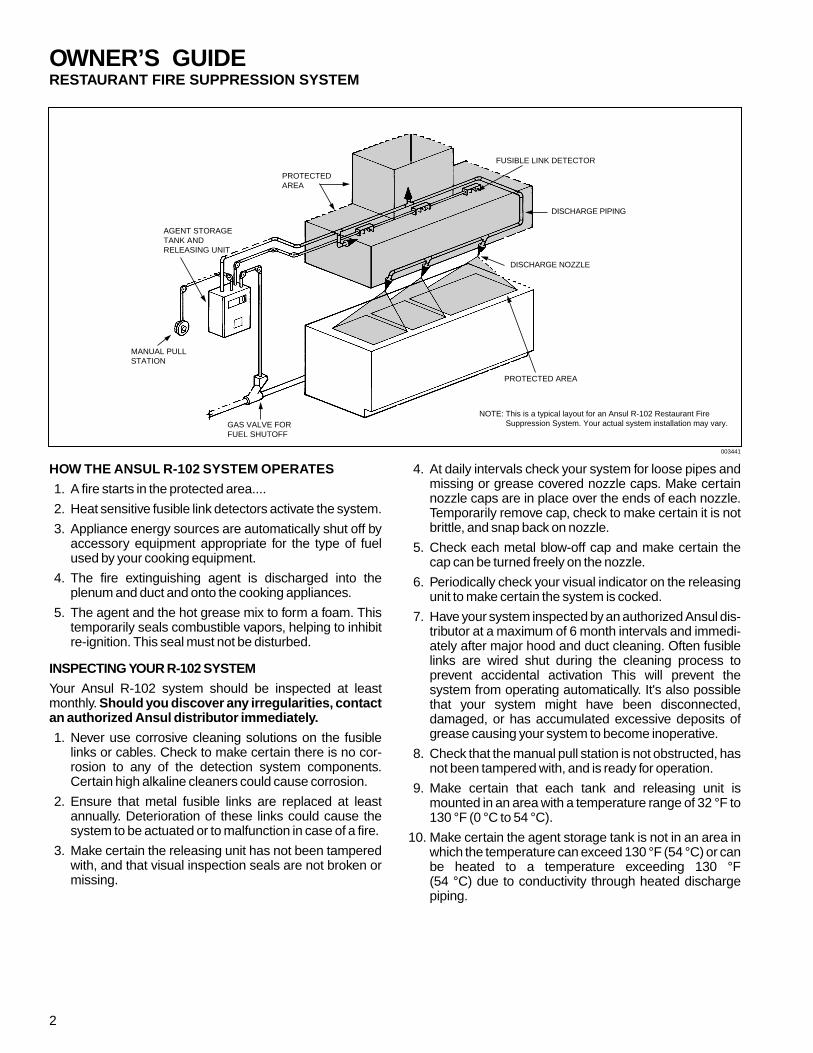
HOW THE ANSUL R-102 SYSTEM OPERATES
1. A fire starts in the protected area....
2. Heat sensitive fusible link detectors activate the system.
3. Appliance energy sources are automatically shut off byaccessory equipment appropriate for the type of fuelused by your cooking equipment.
4. The fire extinguishing agent is discharged into theplenum and duct and onto the cooking appliances.
5. The agent and the hot grease mix to form a foam. Thistemporarily seals combustible vapors, helping to inhibitre-ignition. This seal must not be disturbed.
INSPECTING YOUR R-102 SYSTEM
Your Ansul R-102 system should be inspected at leastmonthly. Should you discover any irregularities, contactan authorized Ansul distributor immediately.
1. Never use corrosive cleaning solutions on the fusiblelinks or cables. Check to make certain there is no cor-rosion to any of the detection system components.Certain high alkaline cleaners could cause corrosion.
2. Ensure that metal fusible links are replaced at leastannually. Deterioration of these links could cause thesystem to be actuated or to malfunction in case of a fire.
3. Make certain the releasing unit has not been tamperedwith, and that visual inspection seals are not broken ormissing.
4. At daily intervals check your system for loose pipes andmissing or grease covered nozzle caps. Make certainnozzle caps are in place over the ends of each nozzle.Temporarily remove cap, check to make certain it is notbrittle, and snap back on nozzle.
5. Check each metal blow-off cap and make certain thecap can be turned freely on the nozzle.
6. Periodically check your visual indicator on the releasingunit to make certain the system is cocked.
7. Have your system inspected by an authorized Ansul dis-tributor at a maximum of 6 month intervals and immedi-ately after major hood and duct cleaning. Often fusiblelinks are wired shut during the cleaning process toprevent accidental activation This will prevent thesystem from operating automatically. It's also possiblethat your system might have been disconnected,damaged, or has accumulated excessive deposits ofgrease causing your system to become inoperative.
8. Check that the manual pull station is not obstructed, hasnot been tampered with, and is ready for operation.
9. Make certain that each tank and releasing unit ismounted in an area with a temperature range of 32 °F to130 °F (0 °C to 54 °C).
10. Make certain the agent storage tank is not in an area inwhich the temperature can exceed 130 °F (54 °C) or canbe heated to a temperature exceeding 130 °F (54 °C) due to conductivity through heated dischargepiping.
MANUAL PULLSTATION
AGENT STORAGETANK ANDRELEASING UNIT
GAS VALVE FORFUEL SHUTOFF
PROTECTEDAREA
FUSIBLE LINK DETECTOR
DISCHARGE PIPING
DISCHARGE NOZZLE
PROTECTED AREA
NOTE: This is a typical layout for an Ansul R-102 Restaurant FireSuppression System. Your actual system installation may vary.
2
003441

OWNER’S GUIDERESTAURANT FIRE SUPPRESSION SYSTEM
3. Call the local fire department.
001635
4. Stand by with the appropriate hand portable fire extin-guisher.
If you need to use it:
a. Pull pin
b. Stand back 10 feet
c. Aim at base of fire, squeeze handle and sweep side toside
001636
IN THE EVENT OF FIRE IN THE PROTECTED AREA
1. Evacuate others from the premises. In a loud, clearvoice say: "WE HAVE A FIRE–PLEASE LEAVE THEBUILDING CAREFULLY, BUT QUICKLY."
001633
2. If the automatic actuation has not yet taken place,operate the system manually as follows:
• Pull handle or pull ring straight out on manual pullstation with enough force to actuate the fire sup-pression system.
001634
Once the fire suppression system is actuated,equipment to shut off the fuel supply to the cookingappliances will operate.
CAUTION!
Do not attempt to extinguish a grease fire with a handportable fire extinguisher before the FireSuppression System has been manually or auto-matically actuated.
3

OWNER’S GUIDERESTAURANT FIRE SUPPRESSION SYSTEM
BEFORE RESUMING BUSINESS
1. Immediately after discharge, call your authorized Ansuldistributor to inspect and recharge your FireSuppression System.
2. Have your Ansul distributor determine the cause of thesystem actuation.
3. Area must be cleaned up within 24 hours after dischargeusing warm water and cleaning detergents.
CLEANUP PROCEDURES
Although there is no unusual cleanup procedure ofANSULEX or ANSULEX LpH agents, due to the alkalinenature of these agents, they should be cleaned fromkitchen surfaces within 24 hours after system discharge.The reaction from the wet chemical agent on cookinggrease or oil produces a foamy bi-product that can bewiped up with a cloth or sponge. The following proceduresshould be followed:
1. The agent is non-toxic; however, food product andcooking grease/oil that has come in contact with theagent will no longer be suitable for human consump-tion and should be discarded.
2. Sponge as much of the agent as possible usingsponges or clean rags. Dispose of these sponges orrags in a local sanitary land fill site in accordance tolocal authorities.
Note: Wear rubber gloves during cleanup as sensitiveskin may become irritated. If the ANSULEXagent or its residue comes in contact with skinor eyes, flush thoroughly with clean water.
3. Using hot, soapy water and either a clean cloth orsponge, wipe away all foamy residue and thoroughlyscrub all surfaces that have come in contact with theagent. Note: Wear rubber gloves during cleanup assensitive skin may become irritated. If the ANSULEXagent or its residue comes in contact with skin or eyes,flush thoroughly with clean water.
4. After thoroughly cleaning all affected surfaces, ade-quately rinse and allow to completely dry before re-energizing the equipment.
WARRANTY
A. Ansul ProductsExcept as indicated in B below, your R-102 System iswarranted to you as the original purchaser for five yearsfrom date of delivery against defects in workmanship andmaterial. Ansul Incorporated (“ANSUL”) will replace orrepair any metal part which, in its opinion, is defective andhas not been tampered with or subjected to misuse,abuse or exposed to highly corrosive conditions.
B. Purchased ProductsThe following items which are not manufactured but pur-chased by ANSUL are warranted against defectsresulting from the manufacturer’s fabrication, process orparts for one year from the date of purchase: detectors,electric manual pull station, time delay relays, ther-mostats, solenoids, switches, fuel shut-off valves, andpressure relief valves. Evaluation of each reportedlydefective relay, valve, etc., returned to ANSUL will bemade by the original manufacturer or an agent thereofand their judgment shall be final.
C. Except as provided in A and B, there are no warranties,express or implied made by ANSUL, concerning thissystem. There are no implied warranties of FITNESSFOR PURPOSE OR MERCHANTABILITY. ANSULshall have no liability for consequential, special or similardamages.
For repairs, parts and service of the Ansul System, contactyour local Ansul representative, or Ansul Incorporated,Marinette, Wisconsin 54143-2542; 800-TO-ANSUL(862-6785).
ANSUL and ANSULEX are registered trademarks.
ANSUL INCORPORATED, ONE STANTON STREET, MARINETTE, WI 54143-2542 715-735-7411 Part No. 418127-02 ©1998 Ansul Incorporated Litho in U.S.A.
CAUTION!
Before attempting any cleanup, make certain that allfuel sources to the equipment to be cleaned have beenshut off. Make certain that the exhaust hood and allappliance electrical controls have been de-energizedto avoid any chance of electrical shock resulting fromthe cleaning process or from electrically conductivealkaline liquid agent and/or its residue.
Make certain all surfaces to be cleaned have cooleddown to room temperature.
Do not use water to clean any appliances that containhot grease or cooking oils. Doing so may result in violentsteaming and/or spattering.

ANSULâ REGULATOR R-102TEST AND RESTAURANTREPLACEMENT FIREINSTRUCTIONS SUPPRESSION
SYSTEMS
R-102 REGULATOR TEST ANDREPLACEMENT INSTRUCTIONS
UL EX 3470 6-1-87 Page 1
FOREWORD
These instructions are intended for the testing and replacement ofAnsul R-102 system regulators. Those who install or serviceR-102 fire suppression systems should understand these instruc-tions as well as the Ansul R-102 Fire Suppression SystemsInstallation, Recharge, and Maintenance Manual (Part No.71961).
REGULATOR TEST FREQUENCY
Prior to April 1986, R-102 regulators WERE NOT date stamped.These regulators require testing at the NEXT SEMI-ANNUALMAINTENANCE EXAMINATION and at twelve-year intervalsthereafter.
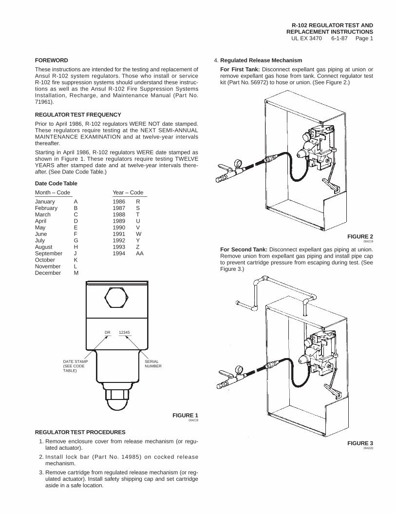
Starting in April 1986, R-102 regulators WERE date stamped asshown in Figure 1. These regulators require testing TWELVEYEARS after stamped date and at twelve-year intervals there-after. (See Date Code Table.)
Date Code Table
Month – Code Year – Code____________ ___________January A 1986 RFebruary B 1987 SMarch C 1988 TApril D 1989 UMay E 1990 VJune F 1991 WJuly G 1992 YAugust H 1993 ZSeptember J 1994 AAOctober KNovember LDecember M
FIGURE 1004218
REGULATOR TEST PROCEDURES
1. Remove enclosure cover from release mechanism (or regu-lated actuator).
2. Install lock bar (Par t No. 14985) on cocked releasemechanism.
3. Remove cartridge from regulated release mechanism (or reg-ulated actuator). Install safety shipping cap and set cartridgeaside in a safe location.
4. Regulated Release Mechanism
For First Tank: Disconnect expellant gas piping at union orremove expellant gas hose from tank. Connect regulator testkit (Part No. 56972) to hose or union. (See Figure 2.)
FIGURE 2004219
For Second Tank: Disconnect expellant gas piping at union.Remove union from expellant gas piping and install pipe capto prevent cartridge pressure from escaping during test. (SeeFigure 3.)
FIGURE 3004220
SERIALNUMBER
DATE STAMP(SEE CODETABLE)
DR 12345___ ______

R-102 REGULATOR TEST ANDREPLACEMENT INSTRUCTIONSUL EX 3470 6-1-87 Page 2
REGULATOR TEST PROCEDURES (Continued)
Pressure Switch: If pressure switch is provided, it shouldremain connected as part of system maintenance test.
NOTICEFor multiple-tank systems, one test kit (Part No.56972) is required for each regulator in thesystem.
5. Regulated Actuator
For First Tank: Disconnect expellant gas piping at union orremove expellant gas hose from tank. Connect regulator testkit (Part No. 56972) to hose or union. (See Figure 4.)
FIGURE 4004221
For Second Tank: Disconnect expellant gas piping at union.Remove union from expellant gas piping and install pipe capto prevent cartridge pressure from escaping during test. (SeeFigure 5.)
FIGURE 5004222
NOTICEMake certain valve is closed on regulator testkit or pressure will escape before test can beperformed.
6. Install LT-30-R nitrogen cartridge(s) (Part No. 5373) intorelease mechanism and each regulated actuator providedwith the system. (Cartridge should be conditioned to approxi-mately 70 °F (21 °C) before test.)
7. Remove lock bar and operate red STRIKE button on releasemechanism to supply pressure to each test kit.
8. Test each regulator by completing the following steps:
a. With test kit valve closed, check reading on pressuregauge for 10 seconds. Correct reading should be 90 to 110psi (621 to 758 kPa). This portion of test verifies correctdead set of regulator.
b. Quickly open test kit valve fully and check gauge whilepressure is bleeding off. Gauge reading should not fallbelow 80 psi (552 kPa). This portion of test verifies regula-tor flow.
c. Close test kit valve and again read pressure gauge. Gaugeshould again read 90 to 110 psi (621 to 758 kPa).
d. Open test kit valve to relieve all pressure from nitrogencartridge.
9. Cock release mechanism using cocking lever (Part No.14995) and insert lock bar (Part No. 14985).
10. Remove empty nitrogen cartridge(s) from release mechanismand each regulated actuator.
11. Remove test kit(s) from release mechanism and each regu-lated actuator.
12. If regulator test WAS NOT successful, replace regulator byreferring to appropriate Regulator Replacement Procedures.If regulator test WAS successful, proceed to Step 13.
13. Reconnect all expellant gas lines.
14. Reset all accessory equipment that was operated by releasemechanism.
15. Remove shipping cap and weigh each nitrogen cartridge thatwas removed before regulator test. Replace if weight is 1/2ounce (14.2 g) or more below weight stamped on cartridge.See R-102 manual for replacement cartridge part numbers.
16. With release mechanism cocked and lock bar in place, screwfully charged cartridge into cartridge receiver. Then install car-tridge into each regulated actuator provided with the system.
17. Hang inspection tag on regulator indicating that the regulatorwas tested or replaced.
18. Remove lock bar and install release mechanism enclosurecover. Insert ring pin through red STRIKE button and attachvisual inspection seal (Part No. 197).
19. Install enclosure cover on each regulated actuator providedwith the system.
CAUTION!
DO NOT HIT RED ‘‘STRIKE’’ BUTTON WHENINSTALLING RELEASE MECHANISM COVER OR SYS-TEM WILL BE ACTUATED CAUSING DISCHARGE OFAGENT.

R-102 REGULATOR TEST ANDREPLACEMENT INSTRUCTIONS
UL EX 3470 6-1-87 Page 3
REGULATOR REPLACEMENT – SYSTEM VARIATIONS
There are three generations of R-102 release mechanismassemblies. Each generation requires a separate procedurefor regulator replacement.
Also, follow applicable third generation procedures when replac-ing regulator in regulated actuator assembly.
First Generation Assembly
The first generation consisted of a release mechanism and regu-lator in a single enclosure. The regulator was connected to thecartridge receiver using a nipple only. See Figure 6.
FIGURE 6004223
Second Generation Assembly
The second generation system also contained a release mech-anism and regulator in a single enclosure. The regulator wasconnected to the cartridge receiver using a special union. SeeFigure 7.
FIGURE 7004224
Third Generation Assembly
The third generation system contains a release mechanism, regu-lator, and agent tank in a single enclosure. The regulator isconnected to the cartridge receiver with a nipple only. The tankis connected to the regulator using expellant gas hose. SeeFigure 8.
FIGURE 8004225
FIRST GENERATION REGULATOR REPLACEMENT PROCE-DURES
First generation regulator replacement requires the use ofHardware Kit (Part No. 77744) which contains the following parts:
1 – Replacement Regulator (Part No. 57667)1 – Union (Part No. 57745)1 – Expellant Gas Hose (Part No. 69337)1 – 1/4 in. Coupling (Part No. 36733)2 – 9/16 in. Washers (Part No. 77747)
1. If a pressure switch is provided, disconnect pressure switchtubing from bottom regulator outlet.
2. Remove pipe section between top regulator outlet and expel-lant gas line union.
3. Using a hacksaw, cut off brass nipple between regulator andcartridge receiver. Cut the nipple as close to the regulator aspossible.
4. Using a No. 5 easy-out, remove remaining portion of nipplefrom cartridge receiver outlet.
WARNING!
HAZARDOUS HIGH PRESSURE COULD CAUSE PERSON-AL INJURY. BEFORE REPLACING REGULATORS, MAKECERTAIN NITROGEN CARTRIDGES HAVE BEENREMOVED FROM RELEASE MECHANISM AND ALL REGU-LATED ACTUATORS. Cartridges should have already beenremoved as part of Regulator Test Procedures.
RELEASEMECHANISM
NITROGENCARTRIDGE
EXPELLANTGAS PIPING
NIPPLE
REGULATOR
RELEASEMECHANISM
NITROGENCARTRIDGE
EXPELLANTGAS HOSE
AGENTTANK
NIPPLEREGULATOR
RELEASEMECHANISM
NITROGENCARTRIDGE
EXPELLANTGAS PIPING
UNION
REGULATOR

R-102 REGULATOR TEST ANDREPLACEMENT INSTRUCTIONSUL EX 3470 6-1-87 Page 4
FIRST GENERATION REGULATOR REPLACEMENT PROCE-DURES (Continued)
5. Inspect to ensure that cartridge receiver outlet is free of dirtor other obstructions.
6. Apply pipe tape to male threads on both ends of unionassembly.
7. With union fully assembled, install adaptor portion of unioninto cartridge receiver outlet. (Union must be assembled toprovide a hex for wrench tightening.) See Figure 9 to identifyadaptor portion of union.
FIGURE 9004226
8. Disassemble union leaving adaptor portion of union installedin cartridge receiver outlet.
9. Using 5/8 in. socket, install union tailpiece (with large hex nut)into inlet of replacement regulator.
10. Make certain O-ring is in place in union tailpiece. Thenreassemble union to connect regulator to cartridge receiveroutlet.
11. Install non-swivel end of expellant gas hose into bottom regu-lator outlet. (Use pipe tape on male threads.) If pressureswitch is provided, connect tubing to top outlet. If pressureswitch is not provided, make certain top outlet is properlyplugged.
NOTICEExpellant gas hose is required in place of pipe(within the enclosure) because top regulatoroutlet will not line up with enclosure knockoutdue to installation of regulator union.
12. Place a 9/16 in. washer over swivel end of expellant gas hoseand insert hose end though knockout previously used forexpellant gas piping. (See Figure 10.)
13. Place other 9/16 in. washer over hose threads that extendthrough knockout. Install a 1/4 in. coupling on hose threads tosecure hose to enclosure as shown in Figure 10. (Use pipetape on male threads.)
FIGURE 10004227
14. Connect piping from 1/4 in. coupling to original expellant gasunion. (Use pipe tape on male threads.)
15. Place system back into service by completing Steps 13through 19 of Regulator Test Procedures.
SECOND GENERATION REGULATOR REPLACEMENT PRO-CEDURES
Replacement regulator(s) (Shipping Part No. 77745) is required tocomplete the following procedures.
1. If a pressure switch is provided, disconnect pressure switchtubing from bottom regulator outlet.
UNIONASSEMBLY
ADAPTOR
O-RING
TAILPIECE
CARTRIDGERECEIVEROUTLET
TO EXPELLANTGAS PIPING
SWIVELEND
9/16 IN.WASHERS(PART NO.77747)
1/4 IN.COUPLING(PART NO.36733)
EXPELLANTGAS HOSE(PART NO.69337)
CAUTION!
Do not use excessive force when assembling union inStep 10 as release mounting spacers could be damaged.
WARNING!
HAZARDOUS HIGH PRESSURE COULD CAUSE PERSON-AL INJURY. BEFORE REPLACING REGULATORS, MAKECERTAIN NITROGEN CARTRIDGES HAVE BEENREMOVED FROM RELEASE MECHANISM AND ALL REGU-LATED ACTUATORS. Cartridges should have already beenremoved as part of Regulator Test Procedures.
R-102 REGULATOR TEST ANDREPLACEMENT INSTRUCTIONS
UL EX 3470 6-1-87 Page 5
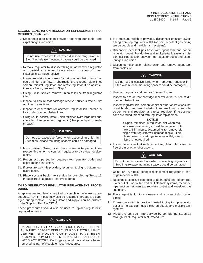
SECOND GENERATION REGULATOR REPLACEMENT PRO-CEDURES (Continued)
2. Disconnect pipe section between top regulator outlet andexpellant gas line union.
3. Remove regulator by disassembling union between regulatorand cartridge receiver. Leave adaptor portion of unioninstalled in cartridge receiver.
4. Inspect regulator inlet screen for dirt or other obstructions thatcould hinder gas flow. If obstructions are found, clear inletscreen, reinstall regulator, and retest regulator. If no obstruc-tions are found, proceed to Step 5.
5. Using 5/8 in. socket, remove union tailpiece from regulatorinlet.
6. Inspect to ensure that cartridge receiver outlet is free of dirtor other obstructions.
7. Inspect to ensure that replacement regulator inlet screen isfree of dirt or other obstructions.
8. Using 5/8 in. socket, install union tailpiece (with large hex nut)into inlet of replacement regulator. (Use pipe tape on malethreads.)
9. Make certain O-ring is in place in union tailpiece. Thenreassemble union to connect regulator to cartridge receiveroutlet.
10. Reconnect pipe section between top regulator outlet andexpellant gas line union.
11. If pressure switch is provided, reconnect tubing to bottom reg-ulator outlet.
12. Place system back into service by completing Steps 13through 19 of Regulator Test Procedures.
THIRD GENERATION REGULATOR REPLACEMENT PROCE-DURES
A replacement regulator is required to complete the following pro-cedures. A 1/4 in. nipple may also be required if threads are dam-aged during removal. The regulator and nipple can be orderedunder Shipping Part No. 77746.
These procedures should also be used to replace regulator inregulated actuator.
1. If a pressure switch is provided, disconnect pressure switchtubing from top regulator outlet (or from expellant gas pipingtee on double and multiple-tank systems).
2. Disconnect expellant gas hose from agent tank and bottomregulator outlet. For double and multiple-tank systems, dis-connect pipe section between top regulator outlet and expel-lant gas line union.
3. Disconnect distribution piping union and remove agent tankfrom enclosure.
4. Unscrew regulator and remove from enclosure.
5. Inspect to ensure that cartridge receiver outlet is free of dirtor other obstructions.
6. Inspect regulator inlet screen for dirt or other obstructions thatcould hinder gas flow. If obstructions are found, clear inletscreen, reinstall regulator, and retest regulator. If no obstruc-tions are found, proceed with regulator replacement.
NOTICEIf nipple remained in regulator inlet when regu-lator was unscrewed, it must be replaced withnew 1/4 in. nipple. (Attempting to remove oldnipple from regulator will damage nipple.) If nip-ple remained in cartridge receiver outlet, a newnipple is not required.
7. Inspect to ensure that replacement regulator inlet screen isfree of dirt or other obstructions.
8. Using 1/4 in. nipple, connect replacement regulator to cart-ridge receiver outlet.
9. Reconnect expellant gas hose to agent tank and bottom reg-ulator outlet. For double and multiple-tank systems, reconnectpipe section between top regulator outlet and expellant gasline union.
10. Place agent tank into enclosure and reconnect distributionpiping.
11. If pressure switch is provided, install tubing to top regulatoroutlet (or to expellant gas piping on double and multiple-tanksystems.
12. Place system back into service by completing Steps 13through 19 of Regulator Test Procedures.
CAUTION!
Do not use excessive force when disassembling union inStep 3 as release mounting spacers could be damaged.
CAUTION!
Do not use excessive force when removing regulator inStep 4 as release mounting spacers could be damaged.
CAUTION!
Do not use excessive force when assembling union inStep 9 as release mounting spacers could be damaged.
CAUTION!
Do not use excessive force when connecting regulator inStep 8 as release mounting spacers could be damaged.
WARNING!
HAZARDOUS HIGH PRESSURE COULD CAUSE PERSON-AL INJURY. BEFORE REPLACING REGULATORS, MAKECERTAIN NITROGEN CARTRIDGES HAVE BEENREMOVED FROM RELEASE MECHANISM AND ALL REGU-LATED ACTUATORS. Cartridges should have already beenremoved as part of Regulator Test Procedures.

For
m N
o. F
-871
25©
1999
Ans
ul In
corp
orat
edLi
tho
in U
.S.A
.ANSUL INCORPORATEDMARINETTE, WI 54143-2542715-735-7411

ANSUL R-102 FIRE SUPPRESSION SYSTEMSDESIGN/INSTALLATION SHEET
Date__________________________
CUSTOMER AUTHORIZED ANSUL DISTRIBUTOR
____________________________________________________ ________________________________________________NAME NAME
____________________________________________________ ________________________________________________STREET STREET
____________________________________________________ ________________________________________________CITY, STATE & ZIP CITY, STATE & ZIP
FILL IN ALL APPROPRIATE DATA BELOW AND CAREFULLY SKETCH HAZARD LAYOUT ON LAST PAGE
SYSTEM
Model(s) and serial numbers ________________________________________________________________________________
Location ____________________________________________________________________________________________
Number of nozzles and Part No. ______________________________________________________________________________
Number of detector(s) and degree rating(s) ____________________________________________________________________
Energy shut-off devices – type and size ________________________________________________________________________
Location ____________________________________________________________________________________________
Other accessory equipment provided (pull station, electric switches, etc.) and location __________________________________
________________________________________________________________________________________________________
Nozzle Nozzle FlowCOOKING/VENTILATING EQUIPMENT Qty. Desc. Nos.
Number of duct(s) and size__________________________________________________ ______ ______ ______
Hood size and plenum size__________________________________________________ ______ ______ ______
Fryer with Drip Board Appliance Type* Length Width Area Length Width Area
1.______________________ ______ ______ ______ ______ ______ ______ ______ ______ ______
2.______________________ ______ ______ ______ ______ ______ ______ ______ ______ ______
3.______________________ ______ ______ ______ ______ ______ ______ ______ ______ ______
4.______________________ ______ ______ ______ ______ ______ ______ ______ ______ ______
5.______________________ ______ ______ ______ ______ ______ ______ ______ ______ ______
6.______________________ ______ ______ ______ ______ ______ ______ ______ ______ ______
7.______________________ ______ ______ ______ ______ ______ ______ ______ ______ ______
8.______________________ ______ ______ ______ ______ ______ ______ ______ ______ ______
* NOTE: List appliances from left to right and indicate those being modified Total Flow Nos. ______
Maximum temperature determined at detector location(s) __________________________________________________________
________________________________________________________________________________________________________
COMMENTS
________________________________________________________________________________________________________
________________________________________________________________________________________________________
________________________________________________________________________________________________________
________________________________________________________________________________________________________
________________________________________________________________________________________________________
________________________________________________________________________________________________________
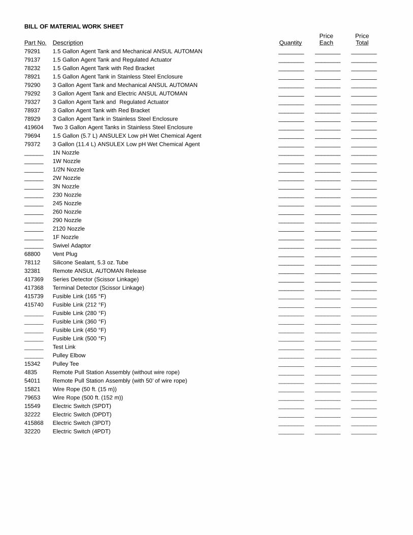
BILL OF MATERIAL WORK SHEET
Price PricePart No. Description Quantity Each Total79291 1.5 Gallon Agent Tank and Mechanical ANSUL AUTOMAN ________ ________ ________
79137 1.5 Gallon Agent Tank and Regulated Actuator ________ ________ ________
78232 1.5 Gallon Agent Tank with Red Bracket ________ ________ ________
78921 1.5 Gallon Agent Tank in Stainless Steel Enclosure ________ ________ ________
79290 3 Gallon Agent Tank and Mechanical ANSUL AUTOMAN ________ ________ ________
79292 3 Gallon Agent Tank and Electric ANSUL AUTOMAN ________ ________ ________
79327 3 Gallon Agent Tank and Regulated Actuator ________ ________ ________
78937 3 Gallon Agent Tank with Red Bracket ________ ________ ________
78929 3 Gallon Agent Tank in Stainless Steel Enclosure ________ ________ ________
419604 Two 3 Gallon Agent Tanks in Stainless Steel Enclosure ________ ________ ________
79694 1.5 Gallon (5.7 L) ANSULEX Low pH Wet Chemical Agent ________ ________ ________
79372 3 Gallon (11.4 L) ANSULEX Low pH Wet Chemical Agent ________ ________ ________
______ 1N Nozzle ________ ________ ________
______ 1W Nozzle ________ ________ ________
______ 1/2N Nozzle ________ ________ ________
______ 2W Nozzle ________ ________ ________
______ 3N Nozzle ________ ________ ________
______ 230 Nozzle ________ ________ ________
______ 245 Nozzle ________ ________ ________
______ 260 Nozzle ________ ________ ________
______ 290 Nozzle ________ ________ ________
______ 2120 Nozzle ________ ________ ________
______ 1F Nozzle ________ ________ ________
______ Swivel Adaptor ________ ________ ________
68800 Vent Plug ________ ________ ________
78112 Silicone Sealant, 5.3 oz. Tube ________ ________ ________
32381 Remote ANSUL AUTOMAN Release ________ ________ ________
417369 Series Detector (Scissor Linkage) ________ ________ ________
417368 Terminal Detector (Scissor Linkage) ________ ________ ________
415739 Fusible Link (165 °F) ________ ________ ________
415740 Fusible Link (212 °F) ________ ________ ________
______ Fusible Link (280 °F) ________ ________ ________
______ Fusible Link (360 °F) ________ ________ ________
______ Fusible Link (450 °F) ________ ________ ________
______ Fusible Link (500 °F) ________ ________ ________
______ Test Link ________ ________ ________
______ Pulley Elbow ________ ________ ________
15342 Pulley Tee ________ ________ ________
4835 Remote Pull Station Assembly (without wire rope) ________ ________ ________
54011 Remote Pull Station Assembly (with 50’ of wire rope) ________ ________ ________
15821 Wire Rope (50 ft. (15 m)) ________ ________ ________
79653 Wire Rope (500 ft. (152 m)) ________ ________ ________
15549 Electric Switch (SPDT) ________ ________ ________
32222 Electric Switch (DPDT) ________ ________ ________
415868 Electric Switch (3PDT) ________ ________ ________
32220 Electric Switch (4PDT) ________ ________ ________
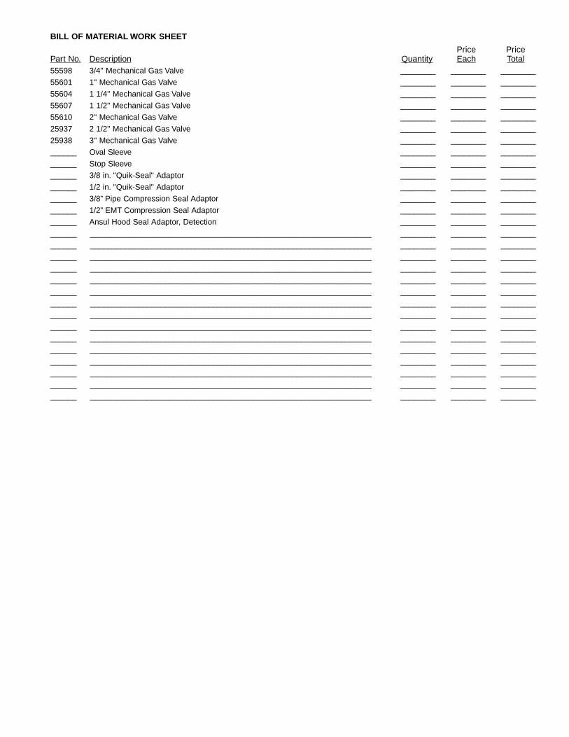
BILL OF MATERIAL WORK SHEET
Price PricePart No. Description Quantity Each Total55598 3/4'' Mechanical Gas Valve ________ ________ ________
55601 1'' Mechanical Gas Valve ________ ________ ________
55604 1 1/4'' Mechanical Gas Valve ________ ________ ________
55607 1 1/2'' Mechanical Gas Valve ________ ________ ________
55610 2'' Mechanical Gas Valve ________ ________ ________
25937 2 1/2'' Mechanical Gas Valve ________ ________ ________
25938 3'' Mechanical Gas Valve ________ ________ ________
______ Oval Sleeve ________ ________ ________
______ Stop Sleeve ________ ________ ________
______ 3/8 in. ''Quik-Seal'' Adaptor ________ ________ ________
______ 1/2 in. ''Quik-Seal'' Adaptor ________ ________ ________
______ 3/8” Pipe Compression Seal Adaptor ________ ________ ________
______ 1/2” EMT Compression Seal Adaptor ________ ________ ________
______ Ansul Hood Seal Adaptor, Detection ________ ________ ________
______ ________________________________________________________________ ________ ________ ________
______ ________________________________________________________________ ________ ________ ________
______ ________________________________________________________________ ________ ________ ________
______ ________________________________________________________________ ________ ________ ________
______ ________________________________________________________________ ________ ________ ________
______ ________________________________________________________________ ________ ________ ________
______ ________________________________________________________________ ________ ________ ________
______ ________________________________________________________________ ________ ________ ________
______ ________________________________________________________________ ________ ________ ________
______ ________________________________________________________________ ________ ________ ________
______ ________________________________________________________________ ________ ________ ________
______ ________________________________________________________________ ________ ________ ________
______ ________________________________________________________________ ________ ________ ________
______ ________________________________________________________________ ________ ________ ________
______ ________________________________________________________________ ________ ________ ________

Part No. 24790-01 ©1997 Ansul Incorporated Litho in U.S.A.ANSULANSUL INCORPORATEDMARINETTE, WI 54143-2542

DISTRIBUTOR CERTIFICATION
INSTALLATION–INSPECTION FOR ANSUL RESTAURANT FIRE SUPPRESSION SYSTEM
Customer Name __________________________________________________________________________________________
Address ________________________________________________________________________________________________
SYSTEM ONE
Model __________________________________________________________________________________________________
Number of nozzles and Part No. ______________________________________________________________________________
Number of detector(s) and degree rating________________________________________________________________________
Energy shut-off devices – type and size ________________________________________________________________________
Other accessory equipment provided __________________________________________________________________________
COOKING/VENTILATING EQUIPMENT
Number of duct(s) and size __________________________________________________ Plenum Size _________________
Cooking Appliances and size (NOTE: List appliances from left to right)
________________________________________________________________________________________________________
________________________________________________________________________________________________________
SYSTEM TWO
Model __________________________________________________________________________________________________
Number of nozzles and Part No. ______________________________________________________________________________
Number of detector(s) and degree rating________________________________________________________________________
Energy shut-off devices – type and size ________________________________________________________________________
Other accessory equipment provided __________________________________________________________________________
COOKING/VENTILATING EQUIPMENT
Number of duct(s) and size __________________________________________________ Plenum Size _________________
Cooking Appliances and size (NOTE: List appliances from left to right)
________________________________________________________________________________________________________
________________________________________________________________________________________________________
TO BE COMPLETED BY INSTALLER
□ YES □ NO The restaurant fire suppression system is UL300 listed and installed in accordance with the manufacturer’sinstructions, NFPA Standard 96 and 17A (current issue), and all applicable state and local codes.
It is a requirement of the manufacturer and recommendation of the National Fire Protection Associationthat the fire system be inspected and maintained every 6 months for proper system operation.
Exceptions to other provisions of NFPA 96 that were observed are noted below.
Exceptions:
□ YES □ NO All electrical work or work provided by others to complete system installation completed.
□ YES □ NO Copy of owner’s manual left with owner.
INSTALLER NAME__________________________________________ SIGNATURE__________________________________
DISTRIBUTOR____________________________________________________________________________________________
ADDRESS ______________________________________________________________________________________________
DATE ______________________________________
Part No. 24789-05 ©1998 Ansul Incorporated Litho in U.S.A.
ANSULANSUL INCORPORATEDMARINETTE, WI 54143-2542
ANSUL is a registered trademark.