ansiotropic damage plasticity
21
Anisotropic damage–plasticity model for concrete George Z. Voyiadjis * , Ziad N. Taqieddin, Peter I. Kattan Department of Civil and Environmental Engineering, Louisiana State University, Taylor Hall 3508-B, Baton Rouge, LA 70803, USA a r t i c l e i n f o Article history: Received 17 December 2007 Received in revised form 30 March 2008 Availa ble online 13 April 2008 Dedicated to Jean-Louis Chaboche Keywords: Anisotropic continuum damage mechanics Concrete plasticity Thermodynamics Strain energy equivalence Damage–elasto-plastic tangent operator a b s t r a c t A material model for concrete is proposed here within the frame- work of a thermodynamically consistent elasto-plasticity–damage theory. Two anisotropic damage tensors and two damage criteria are adopted to describe the distinctive degradation of the mechan- ical properties of concrete under tensile and compressive loadings. The total stress tensor is decomposed into tensile and compressive components in order to accommodate the need for the above men- tioned damage tensors. The plasticity yield criterion presented in this work accounts for the spectral decomposition of the stress ten- sor and allows multiple hardening rules to be used. This plastic yield criterion is used simultaneously with the damage criteria to simulate the physical behavior of concrete. Non-associative flow rule for the plastic strains is used to account for the dilatancy of concrete as a frictional material. The thermodynamic Helmholtz free energy concep t is used to consisten tly derive dis sip ati on potentials for damage and plasticity and to allow evolution laws for different hardening parameters. The evolution of the two dam- age tensors is accounted for through the use of fracture-energy- based continuum dama ge mechanics. An expression is derived for the dama ge–e lasto -pla stic tangent oper ator. The theor etica l framework of the model is described here while the implementa- tion of this model will be discussed in a subsequent paper. Ó 2008 Elsevier Ltd. All rights reserved. 1. Introductio n Concrete prevails as one of the most widely used materials in numerous civil engineering applica- tions due to its workability and formability into various structural components. Understanding and subsequently modeling the mechanical/material behavior of concrete under different loading states 0749-6419/$ - see front matter Ó 2008 Elsevier Ltd. All rights reserve d. doi:10.1016/j.ijplas.2008.04.002 * Corresponding author. E-mail address: [email protected] (G.Z. Voyiadjis). International Journal of Plasticity 24 (2008) 1946–1965 Contents lists available at ScienceDirect International Journal of Plasticity journal homepage: www.elsevier.com/locate/ijplas
-
Upload
ferasalkam -
Category
Documents
-
view
220 -
download
0
Transcript of ansiotropic damage plasticity

7/29/2019 ansiotropic damage plasticity
http://slidepdf.com/reader/full/ansiotropic-damage-plasticity 1/20
Anisotropic damage–plasticity model for concrete
George Z. Voyiadjis *, Ziad N. Taqieddin, Peter I. Kattan
Department of Civil and Environmental Engineering, Louisiana State University, Taylor Hall 3508-B, Baton Rouge, LA 70803, USA
a r t i c l e i n f o
Article history:
Received 17 December 2007
Received in revised form 30 March 2008
Available online 13 April 2008
Dedicated to Jean-Louis Chaboche
Keywords:
Anisotropic continuum damage mechanics
Concrete plasticityThermodynamics
Strain energy equivalence
Damage–elasto-plastic tangent operator
a b s t r a c t
A material model for concrete is proposed here within the frame-
work of a thermodynamically consistent elasto-plasticity–damage
theory. Two anisotropic damage tensors and two damage criteria
are adopted to describe the distinctive degradation of the mechan-
ical properties of concrete under tensile and compressive loadings.
The total stress tensor is decomposed into tensile and compressive
components in order to accommodate the need for the above men-
tioned damage tensors. The plasticity yield criterion presented in
this work accounts for the spectral decomposition of the stress ten-sor and allows multiple hardening rules to be used. This plastic
yield criterion is used simultaneously with the damage criteria to
simulate the physical behavior of concrete. Non-associative flow
rule for the plastic strains is used to account for the dilatancy of
concrete as a frictional material. The thermodynamic Helmholtz
free energy concept is used to consistently derive dissipation
potentials for damage and plasticity and to allow evolution laws
for different hardening parameters. The evolution of the two dam-
age tensors is accounted for through the use of fracture-energy-
based continuum damage mechanics. An expression is derived
for the damage–elasto-plastic tangent operator. The theoretical
framework of the model is described here while the implementa-
tion of this model will be discussed in a subsequent paper.
Ó 2008 Elsevier Ltd. All rights reserved.
1. Introduction
Concrete prevails as one of the most widely used materials in numerous civil engineering applica-
tions due to its workability and formability into various structural components. Understanding and
subsequently modeling the mechanical/material behavior of concrete under different loading states
0749-6419/$ - see front matter Ó 2008 Elsevier Ltd. All rights reserved.
doi:10.1016/j.ijplas.2008.04.002
* Corresponding author.
E-mail address: [email protected] (G.Z. Voyiadjis).
International Journal of Plasticity 24 (2008) 1946–1965
Contents lists available at ScienceDirect
International Journal of Plasticity
jo u rn a l h o me p a g e : www.e ls e v ie r.c o m/lo c a te /ijp la s

7/29/2019 ansiotropic damage plasticity
http://slidepdf.com/reader/full/ansiotropic-damage-plasticity 2/20
is an essential yet challenging task for standard civil engineering applications, not to mention complex
concrete structures that require further understanding in terms of the prediction of failure patterns.
The distinctive behavior of concrete under tensile or compressive loading has also increased the com-
plexity of the constitutive modeling of its behavior (see Fig. 1).
One of the challenging characteristics of concrete is its low tensile strength, particularly at low-
confining pressures, which results in tensile cracking at a very low stress compared with compressive
stresses. The tensile cracking reduces the stiffness of concrete structural components. Therefore, the
use of continuum damage mechanics is necessary to accurately model the degradation in the mechan-
ical properties of concrete. However, the concrete material undergoes also some irreversible (plastic
and damage) deformations during loading such that the continuum damage theories cannot be used
alone, particularly at high-confining pressures. Therefore, the nonlinear material behavior of concrete
can be attributed to two distinct material mechanical processes: damage and plasticity.
Continuum damage mechanics – a combination of the internal state variable theory and the phys-
ical considerations of the irreversible thermodynamic processes – provides a powerful framework for
the derivation of consistent constitutive models suitable for many engineering problems. Several stud-
ies have been performed using continuum damage mechanics to better describe the behavior of var-
ious materials under different loading conditions (e.g. Cordebois and Sidoroff, 1979; Chaboche, 1981;Krajcinovic, 1983; Lemaitre, 1985; Chow and Wang, 1987; Simo and Ju, 1987a; Chaboche, 1988; Lu-
barda and Krajcinovic, 1993; Hansen and Schreyer, 1994; Doghri and Tinel, 2005; Menzel et al., 2005;
Voyiadjis and Kattan, 1999, Voyiadjis et al., 2008; just to mention a few).
Damage in concrete is primarily caused by the propagation and coalescence of micro-cracks, a phe-
nomenon often treated as strain softening in structural analysis. The modeling of crack initiation and
propagation is the intended role of damage mechanics in this model.
Isotropic damage models (scalar based) with one or two (tension and compression) damage vari-
ables have been extensively studied by numerous authors (e.g. Krajcinovic, 1983, 1985; Mazars and
Pijaudier-Cabot, 1989; Lubliner et al., 1989; Lubarda et al., 1994; Faria et al., 1998; Lee and Fenves,
1998; Peerlings et al., 1998; Jason et al., 2004; Bonora et al., 2005; Jason et al., 2006; Pirondi et al.,
2006; Bonora et al., 2006; Wu et al., 2006; Celentano and Chaboche, 2007). In addition, anisotropic(tensor based) damage models (e.g. Dragon and Mroz, 1979; Murakami and Ohno, 1981; Chaboche,
1981; Sidoroff, 1981; Krajcinovic and Fonseka, 1981; Ortiz, 1985; Simo and Ju, 1987a,b; Ju, 1989,
1990; Valanis, 1991; Ramtani et al., 1992; Lubarda and Krajcinovic, 1993; Chaboche, 1993; Voyiadjis
and Abu-Lebdeh, 1994; Yazdani and Schreyer, 1990; Govindjee et al., 1995; Chaboche et al., 1995;
Halm and Dragon, 1996; Fichant et al., 1999; Carol et al., 2001; Hansen et al., 2001; Gatuingt and
Pijaudier-Cabot, 2002; Brunig, 2003; Menzel et al., 2005; Cicekli et al., 2007; Hammi and Horstemeyer,
2007) have been also proposed and investigated.
σ −
ε −
E
(1 ) E ϕ −
−
u f
−
o f
−
eε
−
pε
+
eε
+
σ +
0 u f f + +
=
ε +
E
a b
(1 ) E ϕ +
−
Fig. 1. Concrete behavior under uniaxial (a) tension and (b) compression.
G.Z. Voyiadjis et al. / International Journal of Plasticity 24 (2008) 1946–1965 1947
7/29/2019 ansiotropic damage plasticity
http://slidepdf.com/reader/full/ansiotropic-damage-plasticity 3/20
Plasticity theories have been used successfully in modeling the behavior of metals where the dom-
inant mode of internal rearrangement is the slip process. Although the mathematical theory of plas-
ticity is thoroughly established, its potential usefulness for representing a wide variety of material
behavior has not been yet fully explored. There are many researchers who have used plasticity alone
to characterize the concrete behavior (e.g. Chen and Chen, 1975; William and Warnke, 1975; Bazant,
1978; Dragon and Mroz, 1979; Schreyer, 1983; Chen and Buyukozturk, 1985; Oñate et al., 1988; Voy-
iadjis and Abu-Lebdeh, 1994; Karabinis and Kiousis, 1994; Este and Willam, 1994; Menetrey and Wil-
lam, 1995; Grassl et al., 2002). The main characteristic of these models is a plasticity yield surface that
includes pressure sensitivity, path sensitivity, non-associative flow rule, and work or strain hardening.
However, these works did not address the degradation of the material stiffness due to micro-cracking.
On the other hand, others have used the continuum damage theory alone to model the material non-
linear behavior such that the mechanical effect of the progressive micro-cracking and strain softening
are represented by a set of internal state variables which act on the elastic behavior (i.e. decrease of
the stiffness) at the macroscopic level (e.g. Loland, 1980; Ortiz and Popov, 1982; Krajcinovic, 1983,
1985; Resende and Martin, 1984; Simo and Ju, 1987a,b; Mazars and Pijaudier-Cabot, 1989; Lubarda
et al., 1994). However, there are several facets of concrete behavior (e.g. irreversible deformations,
inelastic volumetric expansion in compression and crack opening/closure effects) that cannot be rep-resented by this approach, which renders it, just as plasticity by itself, to be insufficient. Since both
micro-cracking and irreversible deformations are contributing to the nonlinear response of concrete,
a constitutive model should address equally and in a coupled form the two physically distinct modes
of irreversible changes and should satisfy the basic postulates of thermodynamics.
Plasticity and damage are usually used together to represent the mechanical behavior of concrete
(see Fig. 1). One type of model relies on stress-based plasticity formulated in the effective (undam-
aged) space (e.g. Simo and Ju, 1987a,b; Ju, 1989; 1990; Yazdani and Schreyer, 1990; Lee and Fenves,
1998; Gatuingt and Pijaudier-Cabot, 2002; Jason et al., 2004; Wu et al., 2006; Cicekli et al., 2007),
where the effective stress is defined as the average micro-scale stress acting on the undamaged mate-
rial between micro-defects. Another type of model is based on stress-based plasticity in the nominal
(damaged) stress space (e.g. Bazant and Kim, 1979; Ortiz, 1985; Lubliner et al., 1989; Imran and Pan-tazopoulu, 2001; Ananiev and Ozbolt, 2004; Kratzig and Polling, 2004), where the nominal stress is
defined as the macro-scale stress acting on both the damaged and undamaged materials. Ju (1990) ad-
dressed the characterization of the concrete damage behavior that incorporates anisotropic damage
effects, i.e. different micro-cracking in different directions. Anisotropic damage in concrete yet re-
mains complex and the coupling with plasticity and the application to structural analysis is not
straightforward (e.g. Ju, 1989, 1990; Yazdani and Schreyer, 1990; Voyiadjis and Abu-Lebdeh, 1994;
Meschke et al., 1998; Voyiadjis and Kattan, 1999; Carol et al., 2001; Hansen et al., 2001; Cicekli
et al., 2007), and consequently, it has been avoided by many authors.
In this work, a coupled elasto-plastic–anisotropic damage constitutive model for concrete is formu-
lated based on sound thermodynamics principles. The proposed model includes important aspects of
the concrete nonlinear behavior. It considers different responses of concrete under tension and com-pression. A brief description of anisotropic damage is provided first, followed by the application of the
spectral decomposition technique to the stress and damage effect tensors. Thermodynamically consis-
tent derivations are then presented to introduce the proper evolution laws for the model and to define
the plastic and damage dissipation potentials. The plastic and damage yield criteria are then defined,
followed by the derivation of the damage–elasto-plastic tangent operator. Specific forms of the elastic,
plastic, and damage parts of the Helmholtz free energy function are then specified.
2. Modeling anisotropic damage
Material damage can be used to model specific void and crack surfaces, specific crack and void vol-umes, or the spacing between cracks or voids. It could be represented by scalar damage variables or
the general tensorial representation of damage. Generally the physical interpretation of the damage
variable is introduced as the specific damaged surface area (Kachanov, 1958). In particular, two cases
can be considered: isotropic (scalar) damage and anisotropic (tensorial) damage density of
1948 G.Z. Voyiadjis et al. / International Journal of Plasticity 24 (2008) 1946–1965
7/29/2019 ansiotropic damage plasticity
http://slidepdf.com/reader/full/ansiotropic-damage-plasticity 4/20
micro-cracks, micro-voids, and other microscopic defects. Scalar damage representation is widely
used because of its simplicity in dealing with finite element code implementation. However, for the
proper interpretation of damage in concrete, one should consider the anisotropic damage case. Aniso-
tropic damage is considered in this work.
The effective (undamaged) configuration is used in this study in order to facilitate the formulation
of the damage constitutive equations. That is, the damaged material is modeled first within the effec-
tive elastic–plastic framework, followed by the introduction of the degradation processes that corre-
late the effective undamaged material properties to those of the damaged material through the use of
the following mapping relation (Cordebois and Sidoroff, 1979; Murakami and Ohno, 1981; Voyiadjis
and Kattan, 1999, 2006):
rij ¼ M ijklrkl; ð1Þ
where M ijkl is the fourth-order damage effect tensor. This tensor M ijkl can be of a general form, yet it is
desirable to have a form of M ijkl that will maintain the stress tensor symmetrical after mapping. There
are different definitions for the tensor M ijkl that could be used to symmetrize rij (see Voyiadjis and
Park, 1997a; Voyiadjis and Kattan, 1999, 2006). In this work, the definition presented by Cordebois
and Sidoroff (1982), Lee et al. (1986) and further elaborated by Voyiadjis and Kattan (1999), Voyiadjisand Kattan (2006) is adopted (throughout this work, the following notation for inverse and transpose
will be used for the sake of expediency, ( X À1Þij ¼ X À1ij and ( X TÞij ¼ X Tij):
M ijkl ¼1
2ðdilðdkj À ukjÞ
À1þ ðdil À uilÞ
À1dkjÞ; ð2Þ
where dij is the Kronecker delta and uij is the second-order damage tensor, the evolution of which will
be defined later taking into account the different damage behaviors under different loading patterns.
In this work, the superimposed dash designates a variable in the effective (undamaged) configuration.
The transformation from the effective (undamaged) to the damaged configuration in the elastic re-
gime can be accomplished by utilizing the elastic strain energy equivalence hypothesis (Cordebois and
Sidoroff, 1979; Chow and Wang, 1987; Hansen and Schreyer, 1994; Voyiadjis and Kattan, 1999, 2006
and others.), which basically states that the elastic strain energy for a damaged material is equivalentin form to that of the undamaged (effective) material. This hypothesis can be expressed as follows:
1
2rije
eij ¼
1
2rije
eij: ð3Þ
The total strain tensor in the effective configuration and its damaged counterpart, eij (eij), can be addi-
tively decomposed into elastic eeij (ee
ij) and plastic epij (ep
ij) parts such that:
eij ¼ eeij þ e
pij; eij ¼ ee
ij þ epij : ð4a;bÞ
Using the generalized Hook’s law, the effective stress is given as follows:
rij ¼ E ijkleekl; ð5Þ
where E ijkl is the fourth-order undamaged elastic stiffness tensor. For isotropic linear-elastic materials,
E ijkl is given by:
E ijkl ¼ 2GI dijkl þ KI ijkl; ð6Þ
where I dijkl ¼ I ijkl À 13dijdkl is the deviatoric part of the fourth-order identity tensor I ijkl ¼ 1
2ðdikd jl þ dild jkÞ,
and G ¼ E =ð2ð1 þ mÞÞ and K ¼ E =ð3ð1 À 2mÞÞ are the effective shear and bulk modulii, respectively, with
E being the Young’s modulus and m is the Poisson’s ratio of the initially linear isotropic elastic material.
In the damaged configuration, and similar to the stress–strain relationship in Eq. (5), one writes the
elastic constitutive relation as follows:
rij ¼ E ijkleekl; ð7Þ
where E ijkl is the fourth-order damaged elastic tensor, which is a function of the damage variable uij or
M ijkl. The elastic strain tensors can be expressed using Eqs. (5) and (7) by the following relations:
eeij ¼ E À1
ijklrkl; eeij ¼ E À1
ijklrkl: ð8a;bÞ
G.Z. Voyiadjis et al. / International Journal of Plasticity 24 (2008) 1946–1965 1949

7/29/2019 ansiotropic damage plasticity
http://slidepdf.com/reader/full/ansiotropic-damage-plasticity 5/20
By substituting Eqs. (1) and (8)a into Eq. (3), one can express the damaged elasticity tensor E ijkl in
terms of the corresponding undamaged elasticity tensor E ijkl by the following relation:
E ijkl ¼ M À1ijmnE mnpqM ÀT
pqkl: ð9Þ
Using Eqs. (1), (5) and (7), the following expression relating the elastic strain tensors in the effective
and damaged configurations can be obtained:
eeij ¼ M ÀT
ijpqee
pq: ð10Þ
Moreover, combining Eqs. (8)a, b into Eqs. (4)a,b, respectively, the total strain tensors eij and eij can be
written in the following form:
eij ¼ E À1ijklrkl þ e
pij; eij ¼ E À1
ijklrkl þ epij: ð11a;bÞ
By taking the time derivative of Eqs. (4)a, b, the rate of the total strain tensor in the effective and dam-
aged configurations, _eij and _eij, respectively, can be written as follows:
_eij ¼ _eeij þ _e
pij ; _eij ¼ _ee
ij þ _epij; ð12a;bÞ
where _eeijð_e
eijÞ and _e
pijð_e
pijÞ are the rate of the elastic and plastic strain tensors in the effective and damaged
configurations, respectively.
Analogous to Eq. (11)a, one can write the following relation in the effective configuration
_eij ¼ E À1ijkl
_rkl þ _epij: ð13Þ
However, since E ijkl (the damaged counterpart of E ijkl) is a function of uij, a similar relation to Eq. (13)
cannot be used to write the total strain rate tensor _eij in the damaged configuration. Therefore, an
alternative methodology will be used to obtain that in the following sections.
In this section, anisotropic continuum damage formulations were presented in a general format. No
distinction was made to address the difference in the material response due to various loading behav-
iors. In the following section, the spectral decomposition technique is used to illustrate the adaptationof the above mentioned formulations to the study of concrete materials.
3. Spectral decomposition of the stress tensor
Concrete has different behaviors in tension than in compression. In order to adequately character-
ize the damage in concrete due to tensile and compressive loadings, the Cauchy stress tensor (nominal
or effective) is decomposed into positive and negative parts using the spectral decomposition tech-
nique (e.g. Simo and Ju, 1987a,b; Chaboche, 1992; Voyiadjis and Abu-Lebdeh, 1994; Hansen and
Schreyer, 1995; Krajcinovic, 1996). Hereafter, the superscripts ‘‘+” and ‘‘À” designate, respectively,
tensile and compressive entities. Therefore, rij and rij can be decomposed as follows:
rij ¼ rþij þ rÀij ; rij ¼ rþij þ rÀij ; ð14a;bÞ
where rþij ðrþ
ij Þ and rÀij ðrÀ
ij Þ are the tension and compression parts of the stress in the effective and dam-
aged states, respectively.
The tensile rþij and compressive rÀ
ij parts of the stress tensor rij can be related by:
rþkl ¼ P þklpqr pq; ð15Þ
rÀkl ¼ ½I klpq À P þijpqr pq ¼ P Àklpqr pq; ð16Þ
such that P þijkl þ P Àijkl ¼ I ijkl and P þijkl and P Àijkl are the fourth-order projection tensors defined, respectively
as
P þijpq ¼ X3
k¼1
H ðrðkÞÞnðkÞi nðkÞ
j nðkÞ p nðkÞ
q ; P Àklpq ¼ I klpq À P þijpq; ð17a;bÞ
where H ðrðkÞÞ denotes the Heaviside step function computed at the kth principal stress rðkÞ of rij and
nðkÞi is the kth corresponding unit principal direction. In the subsequent development, the superscript
hat designates a principal value.
1950 G.Z. Voyiadjis et al. / International Journal of Plasticity 24 (2008) 1946–1965

7/29/2019 ansiotropic damage plasticity
http://slidepdf.com/reader/full/ansiotropic-damage-plasticity 6/20
Based on the decomposition in Eq. (14), one can assume the expression in Eq. (1) to be valid for
both tension and compression components of the stress tensor, however, with decoupled damage evo-
lution in tension and compression, one can write:
rþij ¼ M þijklr
þkl; rÀ
ij ¼ M ÀijklrÀkl; ð18a;bÞ
where M þijkl and M Àijkl are the tensile and compressive damage effect tensors which can be expressed,
similar to Eq. (2), in a decoupled form as a function of the tensile and compressive damage variables,
uþij and uÀ
ij , respectively, as follows:
M þijkl ¼1
2ðdilðdkj À uþ
kjÞÀ1 þ ðdil À uþ
il ÞÀ1dkjÞ;
M Àijkl ¼1
2ðdilðdkj À uÀ
kjÞÀ1 þ ðdil À uÀ
il ÞÀ1dkjÞ:
ð19a;bÞ
By substituting Eqs. (18) into Eq. (14)a, one can express the effective stress tensor in terms of the
fourth-order damage effect tensor for tension and compression and their corresponding stresses such
that:
rij ¼ M þijklrþkl þ M Àijklr
Àkl: ð20Þ
Furthermore, substituting Eqs. (15) and (16) into Eq. (20) and comparing the result with Eq. (1), one
can obtain the following relation for the damage effect tensor such that:
M ijpq ¼ M þijklP þklpq þ M ÀijklP Àklpq: ð21Þ
Using Eq. (17)b, the above equation can be rewritten as follows:
M ijpq ¼ ðM þijkl À M ÀijklÞP þklpq þ M Àijpq: ð22Þ
It is important to notice that:
M ijkl 6¼ M
þ
ijkl þ M
À
ijkl ð23Þand
uij 6¼ uþij þ uÀ
ij : ð24Þ
It is also noteworthy that the relation in Eq. (22) enhances a coupling between tensile and compressive
damage through the fourth-order projection tensor P þijkl. Moreover, for isotropic damage, Eq. (21) can
be written as follows:
M ijkl ¼P þijkl
1 À uþþ
P Àijkl
1 À uÀ: ð25Þ
It can be concluded from the above expression that adopting the decomposition of the scalar damage
variable u into a positive u+ and negative uÀ parts still enhances damage anisotropy through the spec-tral decomposition tensors P þijkl and P Àijkl, respectively. However, this anisotropy is weak when com-
pared to the anisotropic damage introduced by a tensorial damage variable as shown in Eq. (22).
4. Consistent thermodynamic formulation
In this section, a general framework for the elasto-plastic–anisotropic damage formulation for con-
crete is developed. Isothermal conditions and rate independence are assumed throughout this work.
Irreversible thermodynamic following the internal variable procedure of Coleman and Gurtin (1967)
and Chaboche (1988) will be applied. The internal variables and potentials used to describe the ther-
modynamic processes are introduced. The Lagrange minimization approach (Calculus of functions of
several variables) is used next to derive the evolution equations for the proposed model.The constitutive equations of the model are derived from the second law of thermodynamics, the
expression of the Helmholtz free energy, the additive decomposition of the total strain rate into elastic
and plastic components, the Clasius–Duhem inequality, and the maximum dissipation principle.
G.Z. Voyiadjis et al. / International Journal of Plasticity 24 (2008) 1946–1965 1951
7/29/2019 ansiotropic damage plasticity
http://slidepdf.com/reader/full/ansiotropic-damage-plasticity 7/20
The Helmholtz free energy can be expressed in terms of a suitable set of internal state variables
that characterize the elastic, plastic, and damage behavior of concrete. In this work the following inter-
nal variables are assumed to satisfactorily characterize the concrete behavior in tension and compres-
sion: the elastic strain tensor eeij, the tensile/compressive equivalent (accumulated) plastic strains,e+ep,
eÀep, the tensile/compressive anisotropic damage tensors, uþij ;u
Àij , and the tensile/compressive equiva-
lent (accumulated) damage variables, uþeq;u
Àeq, such that:
w ¼ wðeeij; e
þep; eÀep;uþij ;u
Àij ;u
þeq;u
ÀeqÞ: ð26Þ
The second-order tensors uÆij characterizes anisotropic damage in the material while the scalars uþ
eq
and uÀeq, defined as uÆ
eq ¼R t
0_uÆ
eqdt , are used to characterize isotropic damage hardening which repre-
sents the generation and propagation of micro-defects in the material, i.e., they cause micro-cracks
and micro-surfaces to grow (Hansen and Schreyer, 1994). Similarly, e+ep and eÀep are the equivalent
tensile and compressive plastic strains that are used here to characterize the plasticity isotropic hard-
ening, eÆep ¼R t
0_eÆepdt .
The Clausius–Duhem inequality for the isothermal case is given as follows:
rij_eij À q
_
wP 0: ð27Þ
Taking the time derivative of Eq. (26), the following expression can be written:
_w ¼ow
oeeij
_eeij þ
ow
ouþij
_uþij þ
ow
ouÀij
_uÀij þ
ow
oeþep_eþep þ
ow
oeÀep_eÀep þ
ow
ouþeq
_uþeq þ
ow
ouÀeq
_uÀeq: ð28Þ
Substituting Eq. (28) into Eq. (27), and making some simplifications, one can obtain the following rela-
tions for any admissible states such that:
rij ¼ qow
oeeij
ð29Þ
and
rij _epij þ Y þij _uþ
ij þ Y Àij _uÀij À c þ _eþep À c À _eÀep À K þ _uþ
eq À K À _uÀeq P 0; ð30Þ
where the damage and plasticity conjugate forces that appear in the above expression are defined as
follows Chaboche (1989):
Y þij ¼ Àqow
ouþij
; Y Àij ¼ Àqow
ouÀij
; K þ ¼ qow
ouþeq
;
K À ¼ qow
ouÀeq
; c þ ¼ qow
oeþep; c À ¼ q
ow
oeÀep:
ð31a — f Þ
Therefore, one can rewrite the Clausius–Duhem inequality to yield the dissipation energy, P, due to
plasticity, Pp, and damage, Pd, such that
P ¼ Pd þPpP 0 ð32Þ
with
Pp ¼ rij _e
pij À c þ _eþep À c À _eÀep
P 0; ð33Þ
Pd ¼ Y þij _uþ
ij þ Y Àij _uÀij À K þ _uþ
eq À K À _uÀeq P 0: ð34Þ
The rate of the internal variables associated with plastic and damage deformations are obtained by
utilizing the calculus of functions of several variables with the plasticity and damage Lagrange multi-
pliers, _kp and _kÆd , and the plastic (F p) and damage ( g +, g À) dissipation potentials such that the following
objective function can be defined:
X ¼ PÀ _kpF p À _kþd g þ À _kÀ
d g À P 0: ð35Þ
Using the well known maximum dissipation principle (Simo and Honein, 1990; Simo and Hughes,
1998), which states that the actual state of the thermodynamic forces (rij, Y Æij ), K ±) is that which
1952 G.Z. Voyiadjis et al. / International Journal of Plasticity 24 (2008) 1946–1965
7/29/2019 ansiotropic damage plasticity
http://slidepdf.com/reader/full/ansiotropic-damage-plasticity 8/20
maximizes the dissipation function over all other possible admissible states, hence, one can maximize
the objective function by using the necessary conditions as follows:
oX
orij
¼ 0;oX
oc Ƽ 0;
oX
oY Æij¼ 0 and
oX
oK Ƽ 0: ð36a—dÞ
Substituting Eq. (32) along with Eqs. (33) and (34) into Eqs. (36) yields the following thermodynamic
evolution laws:
_epij ¼ _kp oF p
orij
; _uþij ¼ _kþ
d
o g þ
oY þij; _uÀ
ij ¼ _kÀd
o g À
oY Àij; _eþep ¼ _kp oF p
oc þ;
_eÀep ¼ _kp oF p
oc À; _uþ
eq ¼ _kþd
o g þ
oK þ; _uÀ
eq ¼ _kÀd
o g À
oK À:
ð37a — gÞ
In what follows, specific forms and functions of the generalized thermodynamically consistent formu-
lations are provided. This includes: the yield and dissipation potentials for damage and plasticity, the
elastic, plastic, and damage parts of the Helmholtz free energy function, and the evolution law for the
state variables of the model.
5. Elasto-plastic–damage model
In this work, the concrete plasticity yield criterion of Lubliner et al. (1989) is adopted. The phenom-
enological concrete model of Lubliner et al. (1989) which was later modified by Lee and Fenves (1998),
is formulated based on isotropic (scalar) stiffness degradation. However, in this work the model of
Lubliner et al. (1989) is extended to anisotropic damage using three loading surfaces: one for plastic-
ity, one for tensile damage, and one for compressive damage. The plasticity and the compressive dam-
age loading surfaces are more dominant in the case of shear loading and compressive crushing (i.e.
modes II and III cracking) whereas the tensile damage loading surface is dominant in the case of mode
I cracking.
The presentation in the following sections can be used for either isotropic or anisotropic damagesince the second-order damage tensor uij degenerates to the scalar damage variable in the case of uni-
axial loading.
5.1. Uniaxial loading
It should be noted that the material behavior concrete is controlled by both plasticity and damage.
In this section, scalar variables will be used.
In the work of Lee and Fenves (1998), which is based on the work of Lubliner et al. (1989), the uni-
axial tensile and compressive stresses, rþij and rÀ
ij , in the damaged configuration are given as (plus and
minus signs cannot be interchanged):
rÆ ¼ ð1 À uÆÞE eÆe ¼ ð1 À uÆÞE ðeÆ À eÆpÞ: ð38a;bÞ
The rate of the equivalent (effective) plastic strains in compression and tension, eÀep and eþep, are,
respectively, given as follows in case of uniaxial loading:
_eþep ¼ _ep11; _eÀep ¼ À_e
p11 ð39a;bÞ
such that
eÀep ¼
Z t
0
_eÀepdt ;eþep ¼
Z t
0
_eþepdt : ð40a;bÞ
Propagation of cracks under uniaxial loading is in the transverse direction to the stress direction.
Therefore, the nucleation and propagation of cracks cause a reduction of the capacity of the load-car-rying area, which causes an increase in the effective stress. This has little effect during compressive
loading since cracks run parallel to the loading direction. However, under a large compressive stress
which causes crushing of the material, the effective load-carrying area is also considerably reduced.
This explains the distinct behavior of concrete in tension and compression as shown in Fig. 1.
G.Z. Voyiadjis et al. / International Journal of Plasticity 24 (2008) 1946–1965 1953

7/29/2019 ansiotropic damage plasticity
http://slidepdf.com/reader/full/ansiotropic-damage-plasticity 9/20
It can be noted from Fig. 1 that during unloading from any point on the strain softening path (i.e.
post peak behavior) of the stress–strain curve, the material response seems to be weakened since the
elastic stiffness of the material is degraded due to damage evolution. Furthermore, it can be noticed
from Figs. 1a and b that the degradation of the elastic stiffness of the material is much different in ten-
sion than in compression, which is more obvious as the plastic strain increases. Therefore, for uniaxial
loading, the damage variable can be represented by two independent damage variables u+ and uÀ.
Moreover, it can be noted that for tensile loading, damage and plasticity are initiated when the equiv-
alent applied stress reaches the uniaxial tensile strength f þo as shown in Fig. 1a whereas under com-
pressive loading, damage is initiated earlier than plasticity. Once the equivalent applied stress reaches
f Ào (i.e. when nonlinear behavior starts) damage is initiated, whereas plasticity occurs once f Àu is
reached. Therefore, generally f þo ¼ f þu for tensile loading, but this is not true for compressive loading
(i.e. f Ào 6¼ f Àu ).
5.2. Multiaxial loading
The evolution equations for the hardening variables are extended now to multiaxial loadings. The
effective plastic strain for multiaxial loading is given as follows (Lubliner et al., 1989; Lee and Fenves,
1998):
_eþep ¼ wðrijÞ_ep
max; _eÀep ¼ Àð1 À wðrijÞÞ _epmin; ð41a;bÞ
where _e
pmax and _
epmin are the maximum and minimum principal values of the plastic strain rate tensor _e
pij
such that _e
p1 > _
ep2 > _
ep3, where _
epmax ¼ _e
p1 and _
epmin ¼ _e
p3.
Eqs. (41)a, b can be written in tensor format as follows:
_eepij ¼ H im
_e
pmj ð42Þ
or in matrix equivalent form as:
_eþep
0
_eÀep
8><>:
9>=>; ¼
H þ 0 0
0 0 0
0 0 H À
264
375
_ep1
_e
p2
_e
p3
8>><>>:
9>>=>>;; ð43Þ
where
H þ ¼ wðrijÞ;H À ¼ Àð1 À wðrijÞÞ: ð44a;bÞ
The dimensionless parameter wðrijÞ is a weight factor depending on principal stresses and is defined as
follows (Lubliner et al., 1989):
wðrijÞ ¼
P3k¼1 rk P3k¼1jrkj ; ð45Þ
where h i is the Macauley bracket, and presented as h xi ¼ 12
ðj xj þ xÞ, k = 1, 2, 3. Note that it can be as-
sumed that wðrijÞ ¼ wðrijÞ. Moreover, depending on the loading state, value of wðrijÞ can be equal to
unity in case of uniaxial tension ( rk P 0, wðrijÞ ¼ 1Þ or equal to zero in the case of uniaxial compres-
sion (rk 6 0;wðrijÞ ¼ 0).
5.3. Plasticity yield surface
To represent the response of concrete subjected to tensile or compressive loadings, a yield criterion
that takes into account the different behaviors of concrete under tension and compression is neces-
sary. Assuming the same yield criterion for both tension and compression for concrete materialscan lead to over/under estimation of plastic deformation (Lubliner et al., 1989). The yield criterion
of Lubliner et al. (1989), that accounts for both tension and compression plasticity, is adopted in this
work. This criterion has been successful in simulating the concrete behavior under uniaxial, biaxial,
1954 G.Z. Voyiadjis et al. / International Journal of Plasticity 24 (2008) 1946–1965

7/29/2019 ansiotropic damage plasticity
http://slidepdf.com/reader/full/ansiotropic-damage-plasticity 10/20
multiaxial, and cyclic loadings (Lee and Fenves, 1998 and the references outlined therein). This crite-
rion is expressed in the effective (undamaged) configuration and is given as follows:
f ¼
ffiffiffiffiffiffiffi3 J 2
q þ aI 1 þ bH ðrmaxÞrmax À ð1 À aÞc ÀðeÀepÞ ¼ 0; ð46Þ
where J 2 ¼sijsij=2 is the second-invariant of the effective deviatoric stress
sij ¼
rij À
rkkdij=3, I 1 ¼
rmm is
the first-invariant of the effective stress rij, eÀep ¼R t
0_eÀepdt is the equivalent plastic strain in the effec-
tive configuration which is defined in Eq. (42), HðrmaxÞ is the Heaviside step function (H ¼ 1 for
rmax > 0 and H ¼ 0 for rmax < 0Þ, and rmax is the maximum principal stress. The parameters a and b
are dimensionless constants which are defined by Lubliner et al. (1989) as follows:
a ¼ð f b0= f À0 Þ À 1
2ð f b0= f À0 Þ À 1; ð47Þ
b ¼ ð1 À aÞ f À0 f þ0
À ð1 þ aÞ; ð48Þ
where f b0, f À0 and f þ0 are the initial equibiaxial, uniaxial compressive and uniaxial tensile yield stresses,
respectively. For more details about the derivation of Eqs. (47) and (48), the reader is referred to Lub-liner et al. (1989).
Since the concrete behavior in compression is more of a ductile behavior, the evolution of the com-
pressive isotropic hardening function c À is defined by the following exponential law:
_c À ¼ bðQ À c Ài Þ_eÀep; ð49Þ
where Q and b are material constants characterizing the saturated stress and the rate of saturation,
respectively, which are obtained in the effective configuration of the compressive uniaxial stress–
strain diagram, and c Ài ¼ c À À f Ào as will be shown in Section 6.2. The rate of the compressive equiva-
lent plastic strain _eÀep is expressed as shown in Eq. (31) and will be further elaborated. A linear
evolution will be assumed for the tensile isotropic hardening c þ.
It should be noted that the above yield surface when mapped in the damaged configuration resultsin an anisotropic function. This is elaborated later in Section 5.7 in Eq. (90).
5.4. Non-associative plasticity flow rule
The shape of the concrete loading surface at any given point in a given loading state should
be obtained by using a non-associative plasticity flow rule. This is important for realistic mod-
eling of the volumetric expansion under compression for frictional materials such as concrete.
Basically, flow rule connects the loading surface and the stress–strain relation. When the current
yield surface f is reached, the material is considered to be in a plastic flow state upon increase
of the loading. In the present model, the flow rule is given as a function of the effective stress
rij by:
_epij ¼ _kp oF p
orij
; ð50Þ
where _kp is the plastic loading factor or known as the Lagrangian plasticity multiplier. The damage
configuration counterpart of Eq. (50) is shown later in Section 5.7.
The plastic potential F p is different than the yield function f (i.e. non-associative) and, therefore, the
direction of the plastic flow oF p=orij is not normal to f . One can adopt the Drucker–Prager function for
F p such that:
F p ¼
ffiffiffiffiffiffiffi3 J 2
q þ apI 1; ð51Þ
where ap is the dilation constant. The corresponding plastic flow direction oF p=orij is then given by:
oF p
orij
¼3
2
sij ffiffiffiffiffiffiffi3 J 2
q þ apdij: ð52Þ
G.Z. Voyiadjis et al. / International Journal of Plasticity 24 (2008) 1946–1965 1955
7/29/2019 ansiotropic damage plasticity
http://slidepdf.com/reader/full/ansiotropic-damage-plasticity 11/20
5.5. The consistency condition and the plastic multiplier
The plasticity consistency condition is applied by taking the time derivative of the plasticity yield
function, _ f ¼ 0, such that the Kuhn–Tucker plasticity consistency conditions are satisfied:
f 6 0;_kp P 0;
_kp f ¼ 0; and
_kp
_
f ¼ 0: ð53Þ
In Eq. (46), the first invariant of the effective stress tensor is defined as I 1 ¼ rmm , while the effective
maximum principal stress rmax can be written in terms of the effective stress tensor and the prin-
cipal directions associated with the effective maximum principal stress according to the spectral
decomposition technique, such that rmax ¼ n pr pqnq. Applying these two changes back into Eq.
(46), one obtains:
f ¼
ffiffiffiffiffiffiffiffiffiffiffiffiffi3
2S ijS ij
r þ armm þ bH ðrmaxÞn pr pqnq À ð1 À aÞc À ¼ 0: ð54Þ
By referring to Section 5.3, one can see that yield criterion, Eq. (54), is a function of the following
parameters:
f ¼ f ðrij;eÀepÞ ¼ 0: ð55Þ
Accordingly the plasticity consistency condition can be written as:
_ f ¼o f
orij
_rij þo f
oeÀep_eÀep ¼ 0; ð56Þ
where o f oeÀep
_eÀep can be expressed as o f oc À
oc À
oeÀep_eÀep.
Differentiating the yield function with respect to the effective stress tensor and again with respect
to the effective compressive equivalent plastic strain gives:
o f
orij ¼
3
2
sij
req þ a
p
dij þ bH ð
rmaxÞn pnqd pidqj ¼
3
2
sij
req þ a
p
dij þ bH ð
rmaxÞnin j; ð57Þo f
oeÀep¼
o f
oc Àoc À
oeÀep¼ Àð1 À aÞbðQ À c Ài Þ: ð58Þ
The rate of the effective compressive equivalent plastic strain _eÀep was defined in Eq. (41)b. By using
the non-associative flow rule (Eq. (50)), _eÀep can be written as follows:
_eÀep ¼ Àð1 À wÞ _epmin ¼ Àð1 À wÞ _kp oF p
ormin
; ð59Þ
where oF p
ormincan be defined as
oF p
ormin¼
3
2
ðrmin À I 1=3Þ ffiffiffiffiffiffiffi3 J 2
q þ ap: ð60Þ
Substituting the additive decomposition of the strain tensor used in defining _rij ¼ E ijkl_ee
kl ¼ E ijklð_ekl À _epklÞ,
the non-associative flow rule, Eq. (50) and Eq. (59) into Eq. (56), one obtains:
_ f ¼o f
orij
E ijkl _ekl À _kp o f
orij
E ijkl
oF p
orkl
À ð1 À wÞ _kp o f
oeÀep
oF p
ormin
¼ 0: ð61Þ
Rearranging Eq. (61) gives the following expression for the effective plastic multiplier _kp:
_kp ¼1h
o f
orij
E ijkl_ekl; ð62Þ
where h is defined as follows:
h ¼o f
orij
E ijkl
oF p
orkl
þ ð1 À wÞo f
oeÀep
oF p
ormin
: ð63Þ
1956 G.Z. Voyiadjis et al. / International Journal of Plasticity 24 (2008) 1946–1965
7/29/2019 ansiotropic damage plasticity
http://slidepdf.com/reader/full/ansiotropic-damage-plasticity 12/20
5.6. Tensile and compressive damage surfaces
The anisotropic damage growth function proposed by Chow and Wang (1987) is adopted in this
study. However, this function is generalized here in order to incorporate both tensile and compressive
damages separately such that:
g Æ ¼
ffiffiffiffiffiffiffiffiffiffiffiffiffiffi ffiffiffiffiffiffiffiffiffi1
2Y Æij LÆ
ijklY Æij
r À K ÆðuÆ
eqÞ 6 0; ð64Þ
where the superscript ± designates tension, +, or compression, À, K ± is the tensile or compressive dam-
age isotropic hardening functions, K Æ ¼ K Æ0 when there is no damage, K Æ0 is the tensile or compressive
initial damage parameter, Lijkl is a fourth-order symmetric tensor (Bielski et al., 2006; Lee et al., 1985;
Hansen and Schreyer, 1994), and Y ij is the damage driving force that characterizes damage evolution
and is interpreted here as the energy release rate (e.g. Voyiadjis and Kattan, 1992a,b, 1999, 2006; Voy-
iadjis and Park, 1997b).
The rate of the equivalent damage _uÆeq is defined as follows (Voyiadjis and Kattan, 1992a,b, 1999;
Voyiadjis and Park, 1997b):
_uÆeq ¼
ffiffiffiffiffiffiffiffiffiffiffiffi_uÆ
ij _uÆij
q with uÆ
eq ¼
Z t
0
_uÆeqdt : ð65Þ
Several types of functions have been proposed in the literature to represent the evolution of the tensile
and compressive damage isotropic hardening K ±. Examples can be found in (Faria et al., 1998; Wu
et al., 2006; Cicekli et al., 2007; just to mention a few). The functions used by Cicekli et al., 2007 for
the evolution of the tensile and compressive damage isotropic hardening K ± are given as:
_K þ ¼K þ
Bþ þK þoK þ
exp ÀBþ 1 ÀK þ
K þo
_uþ
eq ð66Þ
and
_K À ¼K ÀoBÀ exp ÀBÀ 1 À
K À
K Ào
_uÀ
eq: ð67Þ
In these functions, parameters such as K Æo and B± are defined, where K Æo is the initial damage threshold
which is interpreted as the area under the linear portion of the stress–strain diagram such that:
K Æo ¼f Æ2
o
2E ð68Þ
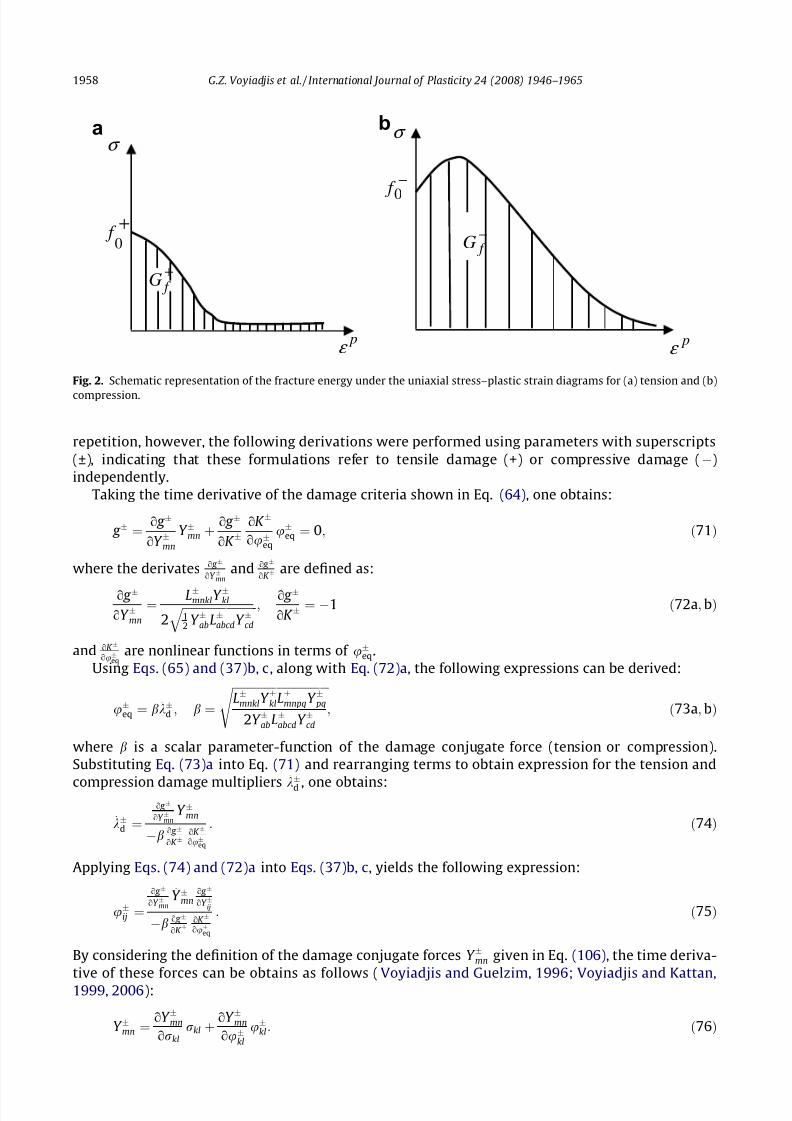
and B±, a material constant, is related to the fracture energy GÆf (shown in Fig. 2 for both tension and
compression) and defined as follows (Oñate et al., 1988):
BÆ ¼ GÆ
f E ‘ f Æ2
0
À 12
" #À1
P 0; ð69Þ
where ‘ is a characteristic length scale parameter that usually has a value close to the size of the small-
est element in a finite element mesh. Therefore, the parameters B± are used in order to reduce mesh-
sensitivity.
The model response in the damage domain is characterized by the damage consistency condition
similar to the Kuhn–Tucker plasticity consistency as follows:
g Æ 6 0; _kÆd g Æ ¼ 0; and _ g Æ
< 0 ) _kÆd ¼ 0
¼ 0 ) _kÆd ¼ 0
¼ 0 ) _kÆ
d> 0
8><>:
9>=>;
()
effectiveðundamaged stateÞ
damage initiation
damage growth
8><>:
: ð70Þ
One should note that using the above damage criteria, it is possible to write specific conditions for ten-
sile and compressive stages; i.e., tensile damage can be initiated independent from compressive dam-
age or parallel to compressive damage. The same applies to compressive damage. In order to avoid
G.Z. Voyiadjis et al. / International Journal of Plasticity 24 (2008) 1946–1965 1957
7/29/2019 ansiotropic damage plasticity
http://slidepdf.com/reader/full/ansiotropic-damage-plasticity 13/20
repetition, however, the following derivations were performed using parameters with superscripts
(±), indicating that these formulations refer to tensile damage (+) or compressive damage (À)
independently.
Taking the time derivative of the damage criteria shown in Eq. (64), one obtains:
_ g Æ ¼o g Æ
oY Æmn
_Y Æmn þo g Æ
oK ÆoK Æ
ouÆeq
_uÆeq ¼ 0; ð71Þ
where the derivates o g Æ
oY Æmnand o g Æ
oK Æare defined as:
o g Æ
oY Æmn
¼LÆ
mnklY Ækl
2 ffiffiffiffiffiffiffiffiffiffiffiffiffiffiffi ffiffiffiffiffiffiffiffiffiffiffi
12 Y ÆabLÆ
abcdY Æcd
q ;o g Æ
oK Ƽ À1 ð72a;bÞ
and oK Æ
ouÆeq
are nonlinear functions in terms of uÆeq.
Using Eqs. (65) and (37)b, c, along with Eq. (72)a, the following expressions can be derived:
_uÆeq ¼ b _kÆ
d ; b ¼
ffiffiffiffiffiffiffiffiffiffiffiffiffiffiffi ffiffiffiffiffiffiffiffiffiffiffiffiffiffiffi ffiffiffiLÆ
mnklY ÆklLÆmnpqY Æ pq
2Y ÆabLÆabcdY Æcd
s ; ð73a;bÞ
where b is a scalar parameter-function of the damage conjugate force (tension or compression).
Substituting Eq. (73)a into Eq. (71) and rearranging terms to obtain expression for the tension and
compression damage multipliers_
kÆ
d , one obtains:
_kÆd ¼
o g Æ
oY Æmn
_Y Æmn
Àb o g Æ
oK ÆoK Æ
ouÆeq
: ð74Þ
Applying Eqs. (74) and (72)a into Eqs. (37)b, c, yields the following expression:
_uÆij ¼
o g Æ
oY Æmn
_Y Æmno g Æ
oY Æij
Àb o g Æ
oK ÆoK Æ
ouÆeq
: ð75Þ
By considering the definition of the damage conjugate forces Y Æmn given in Eq. (106), the time deriva-
tive of these forces can be obtains as follows (Voyiadjis and Guelzim, 1996; Voyiadjis and Kattan,
1999, 2006):
_Y Æmn ¼oY Æmn
orkl
_rkl þoY Æmn
ouÆkl
_uÆkl: ð76Þ
f G+
pε
σ
0 f
+
a b
f G−
σ
pε
0 f
−
Fig. 2. Schematic representation of the fracture energy under the uniaxial stress–plastic strain diagrams for (a) tension and (b)
compression.
1958 G.Z. Voyiadjis et al. / International Journal of Plasticity 24 (2008) 1946–1965
7/29/2019 ansiotropic damage plasticity
http://slidepdf.com/reader/full/ansiotropic-damage-plasticity 14/20
Substituting Eq. (76) back into Eq. (75), and rearranging terms in order to obtain expressions for the
tensile or compressive damage tensors _uÆij , one obtains:
_uÆrs ¼ X rskl _rkl; X rskl ¼ BÀ1
rsij Aijkl; ð77a;bÞ
where
Bijpq ¼ d pidqj Àþ o g Æ
oY Æmn
oY Æmn
ouÆ pq
o g Æ
oY Æij
Àb o g Æ
oK ÆoK Æ
ouÆeq
; Aijkl ¼
o g Æ
oY Æmn
oY Æmn
orkl
o g Æ
oY Æij
Àb o g Æ
oK ÆoK Æ
ouÆeq
: ð78a;bÞ
Eq. (77)a show incremental relations between damage (in tension or compression) and the stress ten-
sor. These equations can be used to derive an incremental relation between the effective and damaged
stress tensors as follows:
The time derivative of the damage effect tensor M ijkl (shown in Eq. (2)) can be written as:
_M ijkl ¼oM ijkl
ouÆrs
_uÆrs: ð79Þ
This can be performed by using the spectral decomposition of the damage effect tensor shown in Eq.
(21). Accordingly _uÆrs in Eq. (79) can be substituted for by using Eq. (77)a to yield:
_M ijkl ¼ Gijklmn _rmn; Gijklmn ¼oM ijkl
ouÆrs
X rsmn: ð80a;bÞ
Eq. (80)a can then be substituted into the time derivative of Eq. (1), which is given as:
_rij ¼ M ijkl _rkl þ _M ijklrkl ð81Þ
to result into the following expression defining the incremental relation between the effective and
damaged stress tensors:
_
rij ¼ mijkl_
rkl; mijkl ¼ M ijkl þ Gijpqklr pq: ð82a;bÞThis incremental relation will be used here to drive the damage–elasto-plastic tangent operator. This
relation shows the stress path dependence of damage in this work.
5.7. Damage–elasto-plastic tangent operator
Starting with the rate of the constitutive equation, _rij ¼ E ijkl_ee
kl ¼ E ijklð_ekl À _epklÞ, in the effective config-
uration, and using the flow rule given in Eq. (50) along with the expression for the plastic multiplier
given by Eq. (62), one can obtain the following constitutive relation in the effective configuration:
_rij ¼ Dijkl_ekl; ð83Þ
where Dijkl is the elastic–plastic tangent operator in the effective configuration given by the following
expression:
Dijkl ¼ E ijkl À1h
E ijrs
oF p
orrs
o f
ormn
E mnkl: ð84Þ
All the parameters in Eq. (84) were previously defined. The objective now is to obtain a relation similar
to Eq. (84) except that it represents the elasto-plastic tangent operator in the damaged configuration.
The damage–elasto-plastic tangent operator is used at a later stage in the course of a finite element
formulation in order to obtain a new stress or strain increment (global nonlinear iterations, e.g., global
Newton–Raphson iterations). At that stage, all the parameters and the tensors within the current
increment have already been determined.
In order to derive an expression for the damage–elasto-plastic tangent operator, an incremental
relationship of the elastic strains in the effective and damaged configurations, _eeij and _ee
ij, respectively,
should exist. The same applies to the incremental plastic strains in the effective and damaged config-
urations, _epij and _e
pkl, respectively. Considering the increments of the elastic strains first, the use of a
G.Z. Voyiadjis et al. / International Journal of Plasticity 24 (2008) 1946–1965 1959
7/29/2019 ansiotropic damage plasticity
http://slidepdf.com/reader/full/ansiotropic-damage-plasticity 15/20
relation similar to Eq. (10) to describe the increments of elastic strains, i.e., _eeij ¼ M ÀT
ijpq _ee
pq, would be
incompatible and therefore, inadmissible (Hansen and Schreyer, 1994). Therefore, the incremental
elastic strain energy equivalency is assumed here (Cordebois and Sidoroff, 1979; Voyiadjis and Guel-
zim, 1996; Voyiadjis and Deliktas, 2000; Voyiadjis and Kattan, 1999, 2006), such that
12
_rij _eeij ¼ 1
2_rij
_eeij: ð85Þ
Substituting Eq. (82)a into Eq. (85), the following relation between the elastic strain rates in the
effective and damaged configurations can be obtained:
_eeij ¼ mÀT
ijkl _eekl: ð86Þ
As for the plastic strain rates, the hypotheses of plastic dissipation equivalence ( Voyiadjis and Thiag-
arajan, 1997; Voyiadjis and Kattan, 1999, 2006) is used here as follows:
rij_e
pij ¼ rij _e
pij : ð87Þ
Substituting Eq. (1) into Eq. (87) results in the following expression that relates the rates of the plastic
strains in the effective and damaged configurations (Lee et al., 1985; Hansen and Schreyer, 1994; Voy-iadjis and Deliktas, 2000; Voyiadjis and Kattan, 1999, 2006):
_epij ¼ M ÀT
ijkl _epkl: ð88Þ
It should be noted here, that the spectral decomposition of the stress tensor can be taken into account
here by realizing that the damage effect tensor M ijkl can be written in terms of its tensile and compres-
sive components as shown in Eq. (21).
Applying Eqs. (12)b, (86), (88), and (82) into Eq. (83), one obtains:
mijkl _rkl ¼ DijklmÀT klmnð_emn À _ep
mnÞ þ DijklM ÀT klmn _e
pmn: ð89Þ
The rate of the plastic strain in the damaged configuration, _epmn, in Eq. (89) can be derived as follows:
the yield function, f , given in Eq. (46) can now be mapped into the damaged configuration (since all the
parameters required for this mapping have already been calculated at this stage) as follows:
f ¼
ffiffiffiffiffiffiffiffiffiffiffiffiffi ffiffiffiffiffiffiffiffiffiffiffiffiffiffiffi3
2H klmnrklrmn
r þ aM mmpqr pq þ bH ðrmaxÞn pM pqmnrmnnq À ð1 À aÞc ÀðeÀepÞ ¼ 0; ð90Þ
where H klmn is a fourth order tensor defined by Voyiadjis and Kattan (1999, 2006) as:
H klmn ¼ N ijklN ijmn; N ijkl ¼ M ijkl À1
3M ppkldij;sij ¼ N ijklrkl ð91a; cÞ
such that
o f
orij ¼
3H ijmnrmn
2 ffiffiffiffiffiffiffiffiffiffiffiffiffi ffiffiffiffiffiffiffiffiffiffi
32
H klrsrklrrs
q þ aM mmij þ bH ð
^rmaxÞn pM pqijnq ð92Þ
and the compressive hardening parameter in the effective configuration is mapped to the damaged
configuration such that:
c ÀðeÀepÞ ¼ ð1 À uÀeqÞc ÀðeÀepÞ: ð93Þ
Therefore, the rate of the plastic strain can be defined in terms of the flow rule in the damaged con-
figuration as follows:
_epij ¼ _kp oF p
orij
; ð94Þ
where
oF p
orij
¼3H ijmnrmn
2 ffiffiffiffiffiffiffiffiffiffiffiffiffi ffiffiffiffiffiffiffiffiffiffi
32
H klrsrklrrs
q þ apM mmij ð95Þ
1960 G.Z. Voyiadjis et al. / International Journal of Plasticity 24 (2008) 1946–1965
7/29/2019 ansiotropic damage plasticity
http://slidepdf.com/reader/full/ansiotropic-damage-plasticity 16/20
and
_kp ¼1
h
o f
orij
E ijkl _ekl; h ¼o f
orij
E ijkl
oF p
orkl
þð1 À wÞ
ð1 À uÀeqÞ
oF p
ormin
; ð96a;bÞ
where
oF p
ormin
¼3ðrmin À I 1=3Þ
2 ffiffiffiffiffiffiffiffiffiffiffiffiffiffi ffiffiffiffiffiffiffiffiffiffiffiffiffi
32
H klmnrklrmn
q þ ap; ð97Þ
which is the damage configuration equivalent to Eq. (60). Note that the norms given by Eqs. (52) and
(95), and Eqs. (60) and (97) are identical, given the assumption in Eq. (85).
Substituting Eq. (94) into Eq. (89) and rearranging terms results in the following expression for the
constitutive relation in the damaged configuration:
_rij ¼ Dijkl _ekl; ð98Þ
where
Dijkl ¼ mÀ1ijmnDmnpqmÀT
pqkl À 1h
mÀ1ijmn o f
ortuE tuklðDmnpqmÀT
pqrs À DmnpqM ÀT pqrsÞ oF
p
orrs
: ð99Þ
In the following sections, specific forms of the Helmholtz free energy function required to develop the
damage energy release rates and the evolution laws for the concrete material model are introduced.
6. The Helmholtz free energy function
Here, we will assume that the Helmholtz free energy function w consists of three parts: elastic,
plastic, and damage parts. The elastic Helmholtz free energy is defined to establish the plastic–damage
constitutive relation with the internal variables, which results in the damage thermodynamic release
rates in tension and compression (damage conjugate forces Y Æij ) used in the damage criteria g ±. The
plastic part introduces the mechanism defining the evolution law for the plastic strains and the mate-rial hardening. The damage part allows the evolution of the damage scalar parameters which repre-
sents the generation and propagation (possibly intersection) of micro-cracks in the concrete material.
6.1. The elastic part of the Helmholtz free energy function
The principle of elastic energy equivalence, which was introduced by Cordebois and Sidoroff
(1979), is used here to define the elastic part of the Helmholtz free energy function. In the damaged
configuration, it is given as a function of the degraded stress and the damage tensor:
qweðee
kl;uÆij Þ ¼
1
2rijE À1
ijklðuÆij Þrkl ¼
1
2rije
eij ¼
1
2ee
ijE ijkleekl; ð100Þ
whereas, in the effective configuration, it is given as a function of the effective stress:
qweðeeij;0Þ ¼
1
2ee
ijE ijkleekl: ð101Þ
The principle of elastic energy equivalence implies that the two preceding forms for the stored elastic
energy are equivalent (Hansen and Schreyer, 1994). Applying Eq. (1) into Eq. (101) and using the prin-
ciple of elastic energy equivalence, one can retrieve the following expression for E À1ijkl (which is the in-
verse of E ijkl given in Eq. (9)):
E À1ijkl ¼ M T
ijmnE À1mnpqM pqkl: ð102Þ
Now, one can obtain expressions for the damage driving forces Y
Æ
ij from Eqs. (31)a, b and (100) asfollows:
Y Ærs ¼ À1
2rij
oE À1ijkl
ouÆrs
rkl: ð103Þ
G.Z. Voyiadjis et al. / International Journal of Plasticity 24 (2008) 1946–1965 1961

7/29/2019 ansiotropic damage plasticity
http://slidepdf.com/reader/full/ansiotropic-damage-plasticity 17/20
By taking the derivative of Eq. (102) with respect to the damage parameters uÆij , one obtains:
oE À1ijkl
ouÆrs
¼oM T
ijmn
ouÆrs
E À1mnpqM pqkl þ M T
ijmnE À1mnpq
oM pqkl
ouÆrs
: ð104Þ
Now, by substituting Eq. (104) into Eq. (103), one obtains the following expression for Y Æij
:
Y Ærs ¼ À1
2rij
oM T ijmn
ouÆrs
E À1mnpqM pqkl þ M T
ijmnE À1mnpq
oM pqkl
ouÆrs
!rkl: ð105Þ
For a symmetric damage effect tensor M ijkl, the expression between the parentheses can be simplified
to yield the following (Lee et al., 1985; Voyiadjis and Guelzim, 1996; Voyiadjis and Kattan, 1999,
2006):
Y Ærs ¼ Àrij
oM ijmn
ouÆrs
E À1mnpqM pqklrkl: ð106Þ
The equivalent to Eq. (106) in terms of the effective stresses can be derived in a similar way to yield:
Y Ærs ¼ Àrvw
oM À1vwij
ouÆrs
M ijtuE À1tumnrmn: ð107Þ
6.2. The plastic part of the Helmholtz free energy function
The plastic part of the Helmholtz free energy function given in terms of the effective plastic strain
in order to derive the evolution of the hardening parameters used in the yield function in Eq. (39) is
given as follows:
qwp ¼ f þo eþep þ1
2hðeþepÞ2 þ f Ào eÀep þ Q eÀep þ
1
bexpðÀbeÀepÞ
: ð108Þ
Substituting Eq. (108) into Eqs. (31)e, f yields the following expressions for the plasticity conjugateforces c þ and c À:
c þ ¼ f þo þ heþep; ð109Þ
c À ¼ f Ào þ Q 1 À expðÀbeÀepÞ½ : ð110Þ
By taking the time derivative of Eqs. (109) and (110) one can easily retrieve Eq. (49) and its tensile
counterpart (presented below), representing the evolution equations for the hardening parameters
in tension and compression.
_c þ ¼ h_eþep: ð111Þ
6.3. The damage part of Helmholtz free energy function
The damage part of the Helmholtz free energy function is postulated to have the following form:
qwd ¼ K Æo uÆ
eq þ1
BÆð1 À uÆ
eqÞ lnð1 À uÆeqÞ þ uÆ
eq
n o ; ð112Þ
where K Æo is the initial damage threshold defined in Eq. (68) and B± are material constants which are
expressed in terms of the fracture energy and an intrinsic length scale, Eq. (69).
Substituting Eq. (112) into Eqs. (31)c, d, one can easily obtain the following expressions for the
damage driving forces K ±:
K
Æ
¼ K
Æ
o 1 À
1
BÆ lnð1 ÀuÆ
eqÞ
: ð113Þ
By taking the time derivative of the above expression one retrieves the rate form of the damage hard-
ening/softening function K ± presented in Eqs. (66) and (67) such that (with minor modification in Eq.
(66)):
1962 G.Z. Voyiadjis et al. / International Journal of Plasticity 24 (2008) 1946–1965
7/29/2019 ansiotropic damage plasticity
http://slidepdf.com/reader/full/ansiotropic-damage-plasticity 18/20
_K Æ ¼K ÆoBÆ exp ÀBÆ 1 À
K Æ
K Æo
!" #_uÆ
eq: ð114Þ
This concludes the derivation of all the components constituting the elasto-plastic–anisotropic dam-
age material model for concrete.
7. Conclusions
A new model to predict the elasto-plastic–anisotropic damage behavior of concrete is derived in
this work by applying sound thermodynamic principles. Tensile and compressive damage in concrete
are characterized and accounted for by using: two damage tensors (tension/compression) that are
used to define two fourth order damage effect tensors for mapping the stresses from the effective
to the damaged configurations, different tensile and compressive damage hardening rules character-
izing damage evolution, and two (tensile/compressive) damage conjugate forces resulting from the
application of the strain energy equivalence hypothesis. These two damage release rates are used to
define two damage criteria, one for tension and the other for compression. The damage tensors are
defined at both the total and incremental forms and are stress path dependent.Concrete plasticity is formulated within the effective stress space with multiple hardening rules to
allow for different performances under tension and compression. The spectral decomposition tech-
nique is used here to resolve the stress tensor into tensile and compressive components in order to
facilitate the derivation of the above mentioned tensors. The verification of the model and its material
parameters, as well as its numerical aspects and coding algorithms, will be forthcoming.
References
Ananiev, S., Ozbolt, J., 2004. Plastic–damage model for concrete in principal directions. In: Li, V., Leung, C.K.Y., William, K.J.,Billington S.L. (Eds), Fracture Mechanics of Concrete Structures, pp. 271–278.
Bazant, Z.P., Kim, S-S., 1979. Plastic-fracturing theory for concrete. J. Eng. Mech. Div. (ASCE) 105, 407–428.
Bazant, Z.P., 1978. On endochronic inelasticity and incremental plasticity. Int. J. Solids Struct. 14, 691–714.Bielski, J., Skrzypek, J., Kuna-Ciskal, H., 2006. Implementation of a model of coupled elastic–plastic unilateral damage material to
finite element code. Int. J. Damage Mech. 15, 5–39.Bonora, N., Gentile, D., Pirondi, A., Newaz, G., 2005. Ductile damage evolution under triaxial state of stress: theory and
experiments. Int. J. Plasticity 21, 981–1007.Bonora, N., Ruggiero, A., Esposito, L., Gentile, G., 2006. CDM modeling of ductile failure in ferritic steels: assessment of the
geometry transferability of model parameters. Int. J. Plasticity 22, 2015–2047.Brunig, M., 2003. An anisotropic ductile damage model based on irreversible thermo-dynamics. Int. J. Plasticity 19, 1679–1713.Carol, I., Rizzi, E., William, K.J., 2001. On the formulation of anisotropic elastic degradation. II. Generalized pseudo-Rankine
model for tensile damage. Int. J. Solids Struct. 38, 519–546.Celentano, D.J., Chaboche, J.L., 2007. Experimental and numerical characterization of damage evolution in steels. Int. J. Plasticity
23, 1739–1762.Chaboche, J.L., 1981. Continuous damage mechanics: a tool to describe phenomena before crack initiation. Nucl. Eng. Des. 64,
233–247.Chaboche, J.L., 1988. Continuum damage mechanics. Part I: general concepts. J. Appl. Mech. 55, 59–64.Chaboche, J.L., 1989. Constitutive equations for cyclic plasticity and cyclic viscoplasticity. Int. J. Plasticity 5, 247–302.Chaboche, J.L., 1992. Damage induced anisotropy: on the difficulties associated with the active/passive unilateral conditions. Int.
J. Damage Mech. 2, 148–171).Chaboche, J.L., 1993. Development of continuum damage mechanic for elastic solids sustaining anisotroic and unilateral
damage. Int. J. Damage Mech. 2, 311–329.Chaboche, J.L., Lesne, P.M., Maire, J.F., 1995. Continuum damage mechanics, anisotropy and damage deactivation for brittle
materials like concrete and ceramic composites. Int. J. Damage Mech. 4, 5–22.Chen, A.C.T., Chen, W.F., 1975. Constitutive relations for concrete. J. Eng. Mech. Div. ASCE 101, 465–481.Chen, E.S., Buyukozturk, O., 1985. Constitutive model for concrete in cyclic compression. J. Eng. Mech. Div. ASCE 111, 797–814.Chow, C.L., Wang, J., 1987. An anisotropic theory of elasticity for continuum damage mechanics. Int. J. Fracture 33, 2–16.Cicekli, U., Voyiadjis, G.Z., Abu Al-Rub, R.K., 2007. A plasticity and anisotropic damage model for plain concrete. Int. J. Plasticity
23, 1874–1900.Coleman, B.D., Gurtin, M.E., 1967. Thermodynamics with internal state variables. J. Chem. Phys. 47 (2), 597–613.Cordebois, J.P., Sidoroff, F., 1979. Anisotropic damage in elasticity and plasticity. J. Mec. Theor. Appl., Numero Special, 40–45.
Cordebois, J.P., Sidoroff, F., 1982. Damaged induced elastic anisotropy. In: Boehler, J.P. (Ed.), Proceedings of the EuromechColloquimum 115 on Mechanical Behavior of Anisotropic Solids, Villard-de-Lans, France, June 19–22, pp. 764–774.
Doghri, I., Tinel, L., 2005. Micromechanical modeling and computation of elasto-plastic materials reinforced with distributed-orientation fibers. Int. J. Plasticity 21 (10), 1919–1940.
Dragon, A., Mroz, Z., 1979. A continuum model for plastic-brittle behavior of rock and concrete. Int. J. Eng. Sci. 17, 121–137.
G.Z. Voyiadjis et al. / International Journal of Plasticity 24 (2008) 1946–1965 1963

7/29/2019 ansiotropic damage plasticity
http://slidepdf.com/reader/full/ansiotropic-damage-plasticity 19/20
Este, G., Willam, K.J., 1994. A fracture-energy based constitutive formulation for inelastic behavior of plain concrete. J. Eng.Mech., ASCE 120, 1983–2011.
Fichant, S., Borderie, C.L., Pijaudier-Cabot, G., 1999. Isotropic and anisotropic descriptions of damage in concrete structures.Mech. Cohes. -Frict. Mater. 4, 339–359.
Faria, A., Oliver, J., Cervera, M., 1998. A strain-based plastic viscous-damage model for massive concrete structures. Int. J. SolidsStruct. 35, 1533–1558.
Gatuingt, F., Pijaudier-Cabot, G., 2002. Coupled damage and plasticity modeling in transient dynamic analysis of concrete. Int. J.Numer. Anal. Methods Geomech. 26, 1–24.
Govindjee, S., Kay, G.J., Simo, J.C., 1995. Anisotropic modelling and numerical simulation of brittle damage in concrete. Int. J.Numer. Methods Eng. 38, 3611–3633.
Grassl, P., Lundgren, K., Gylltoft, K., 2002. Concrete in compression: a plasticity theory with a novel hardening law. Int. J. SolidsStruct. 39, 5205–5223.
Halm, D., Dragon, A., 1996. A model of anisotropic damage by mesocrack growth; unilateral effect. Int. J. Damage Mech. 5, 384–402.
Hammi, Y., Horstemeyer, M.F., 2007. A physically motivated anisotropic tensorial representation of damage with separatefunctions for void nucleation, growth, and coalescence. Int. J. Plasticity 23, 1641–1678.
Hansen, E., William, K., Carol, I., 2001. A two-surface anisotropic damage/plasticity model for plain concrete. In: de Borst, R.,Mazars, J., Pijaudier-Cabot, G., van Mier, J.G.M. (Eds.), Fracture Mechanics of Concrete Structures. Lisse, Balkema, pp. 549–556.
Hansen, N.R., Schreyer, H.L., 1994. A thermodynamically consistent framework for theories of elastoplasticity coupled withdamage. Int. J. Solids Struct. 31 (3), 359–389.
Hansen, N.R., Schreyer, H.L., 1995. Damage deactivation. J. Appl. Mech. 62, 450–458.Imran, I., Pantazopoulu, S.J., 2001. Plasticity model for concrete under triaxial compression. J. Eng. Mech. 127, 281–290.
Jason, L., Pijaudier-Cabot, G., Huerta, A., Crouch, R., Ghavamian, S., 2004. An elastic plastic damage formulation for the behaviorof concrete. In: Li, V., Leung, C.K.Y., William, K.J., Billington, S.L., (Eds), Fracture Mechanics of Concrete Structures, pp. 549–556.
Jason, L., Huerta, A., Pijaudier-Cabot, G., Ghavamian, S., 2006. An elastic plastic damage formulation for concrete: application toelementary tests and comparison with an isotropic damage model. Comput. Methods Appl. Mech. Eng. 195, 7077–7092.
Ju, J.W., 1989. On energy-based coupled elasto-plastic damage theories: constitutive modeling and computational aspects. Int JSolids Struct. 25, 803–833.
Ju, J.W., 1990. Isotropic and anisotropic damage variables in continuum damage mechanics. ASCE J. Eng. Mech. 116, 2764–2770.Kachanov, L.M., 1958. On the creep fracture time. Izv. Akad. Nauk USSR Otd. Tech 8, 26–31 (in Russian).Kratzig, W., Polling, R., 2004. An elasto-plastic damage model for reinforced concrete with minimum number of material
parameters. Comput. Struct. 82, 1201–1215.Karabinis, A.I., Kiousis, P.D., 1994. Effects of confinement on concrete columns: a plasticity theory approach. ASCE J. Struct. Eng.
120, 2747–2767.Krajcinovic, D., Fonseka, G.U., 1981. The continuous damage theory of brittle materials. Part I: General Theory. J. Appl. Mech. 48,
809–815.Krajcinovic, D., 1983. Continuum damage mechanics. Appl. Mech. Rev. 37, 1–6.Krajcinovic, D., 1985. Continuous damage mechanics revisited: basic concepts and definitions. J. Appl. Mech. 52, 829–834.Krajcinovic, D., 1996. Damage Mechanics. North-Holland, Amsterdam.Lemaitre, J., 1985. Coupled elasto plasticity and damage constitutive equations. Comput. Methods Appl. Mech. Eng. 51, 31–49.Lee, H., Peng, K., Wang, J., 1985. An anisotropic damage criterion for deformation instability and its application to forming limit
analysis of metal plates. Eng. Fracture Mech. 21, 1031–1054.Lee, H., Li, G., Lee, S., 1986. The Influence of anisotropic damage on the elastic behavior of materials. In: International Seminar on
Local Approach of Fracture, Moret-sur-Loing, France, pp. 79–90.Lee, J., Fenves, G.L., 1998. A plastic–damage model for cyclic loading of concrete structures. J. Eng. Mech., ASCE 124, 892–900.Loland, K.E., 1980. Continuous damage model for load-response estimation of concrete. Cem. Concr. Res. 10, 395–402.Lubarda, V.A., Krajcinovic, D., 1993. Damage tensors and the crack density distribution. Int. J. Solids Struct. 30, 2859–2877.Lubarda, V.A., Kracjinvovic, D., Mastilovic, S., 1994. Damage model for brittle elastic solids with unequal tensile and compressive
strength. Eng. Fracture Mech. 49, 681–697.Lubliner, J., Oliver, J., Oller, S., Oñate, E., 1989. A plastic–damage model for concrete. Int. J. Solids Struct. 25, 299–326.Mazars, J., Pijaudier-Cabot, G., 1989. Continuum damage theory – application to concrete. J. Eng. Mech. 115, 345–365.Menetrey, Ph., Willam, K.J., 1995. Triaxial failure criterion for concrete and its generalization. ACI Struct. J. 92, 311–318.Menzel, A., Ekh, M., Runesson, K., Steinmann, P., 2005. A framework for multiplicative elastoplasticity with kinematic hardening
coupled to anisotropic damage. Int. J. Plasticity 21, 397–434.Meschke, G., Lackner, R., Mang, H., 1998. An anisotropic elastoplastic–damage model for plain concrete. Int. J. Numer. Methods
Eng. 42, 703–727.Murakami, S., Ohno, N., 1981. A continuum theory of creep and creep damage. In: Proceedings of the Third IUTAM Symposium
on Creep in Structures, Springer, Berlin, pp. 422–444.Oñate, E., Oller, Oliver, S., Lubliner, J., 1988. A constitutive model of concrete based on the incremental theory of plasticity. Eng.
Comput. 5, 309–319.Ortiz, M., 1985. A constitutive theory for the inelastic behavior of concrete. Mech. Mater. 4 (1), 67–93.Ortiz, M., Popov, E.P., 1982. Plain concrete as a composite material. Mech. Mater. 1, 139–150.Peerlings, R.H.J., de Borst, R., Brekelmans, W.A.M., Geers, M.G.D., 1998. Gradient-enhanced damage modelling of concrete
fracture. Mech. Cohes.-Frict. Mater. 3, 323–342.Pirondi, A., Bonora, N., Steglich, D., Brocks, W., Hellmann, D., 2006. Simulation of failure under cyclic plastic loading by damage
models. Int. J. Plasticity 22, 2146–2170.Ramtani, S., Berthaud, Y., Mazars, J., 1992. Orthotropic behavior of concrete with directional aspects: modelling and
experiments. Nucl. Eng. Des. 133, 97–111.
1964 G.Z. Voyiadjis et al. / International Journal of Plasticity 24 (2008) 1946–1965
7/29/2019 ansiotropic damage plasticity
http://slidepdf.com/reader/full/ansiotropic-damage-plasticity 20/20
Resende, L., Martin, J.B., 1984. A progressive damage continuum model for granular materials. Comput. Methods Appl. Mech.Eng. 42, 1–18.
Schreyer, H.L., 1983. Third-invariant plasticity theory for frictional materials. J. Struct. Mech. 11, 177–196.Sidoroff, F., 1981. Description of anisotiopic damage application to elasticity. In: IUTAM Colloqium on Physical Nonlinearities in
Structural Analysis. Springer-Verlag, Berline, pp. 237–244.Simo, J.C., Honein, T., 1990. Variational formulation, discrete conservation laws, and path domain independent integrals for
elasto-viscoplasticity. J. Appl. Mech., Trans. ASME 57, 488–497.Simo, J.C., Hughes, T.J.R., 1998. Computational inelasticity. In: Interdisciplanary Applied Mathematics. Springer, New York.Simo, J.C., Ju, J.W., 1987a. Strain and stress-based continuum damage. Model. Part I: Formulation. Int. J. Solids Struct. 23, 821–
840.Simo, J.C., Ju, J.W., 1987b. Strain- and stress-based continuum damage models. Part II: computational aspects. Int. J. Solids
Struct. 23, 841–869.Valanis, K.C., 1991. A global damage theory and the hyperbolicity of the wave problem. J. Appl. Mech. 58, 311–316.Voyiadjis, G.Z., Deliktas, B., 2000. A coupled anisotropic damage model for the inelastic response of composite materials.
Comput. Methods Appl. Mech. Eng. 183, 159–199.Voyiadjis, G.Z., Guelzim, Z., 1996. A coupled incremental damage and plasticity theory for metal matrix composites. J. Mech.
Behav. Mater. 6, 193–219.Voyiadjis, G.Z., Kattan, P.I., 1992a. A plasticity–damage theory for large deformations of solids, Part I: theoretical formulation.
Int. J. Eng. Sci. 30, 1089–1108.Voyiadjis, G.Z., Kattan, P.I., 1992b. Finite strain plasticity and damage in constitutive modeling of metals with spin tensors. Appl.
Mech. Rev. 45, 95–109.
Voyiadjis, G.Z., Abu-Lebdeh, T.M., 1994. Plasticity model for concrete using the bounding surface concept. Int. J. Plasticity 10, 1–21.
Voyiadjis, G.Z., Park, T., 1997a. Anisotropic damage effect tensors for the symmetrization of the effective stress tensor. J. Appl.Mech., ASME 64, 106–110.
Voyiadjis, G.Z., Park, T., 1997b. Local and interfacial damage analysis of metal matrix composites using finite element method.Eng. Fract. Mech. 56 (4), 483–511.
Voyiadjis, G.Z., Kattan, P.I., 1999. Advances in Damage Mechanics: Metals and Metals Matrix Composites. Elsevier, Oxford.Voyiadjis, G.Z., Kattan, P., 2006. Advances in Damage Mechanics: Metals and Metal Matrix Composites, with an Introduction to
Fabric Tensors, second ed. Elsevier, Oxford.Voyiadjis, G.Z., Thiagarajan, G., 1997. Micro and macro anisotropic cyclic damage plasticity models for MMCS. Int. J. Eng. Sci. 35
(7), 467–484.Voyiadjis, G.Z., Taqieddin, Z.N., Kattan, P.I., 2008. Theoretical formulation of a coupled elastic-plastic anisotropic damage model
for concrete using the strain energy equivalence concept. Int. J. Damage Mech., in press.William, K.J., Warnke, E.P., 1975. Constitutive model for the triaxial behavior of concrete. In: International Association of Bridge
and Structural Engineers, Seminar on Concrete Structure Subjected to Triaxial Stresses, Paper III-1, Bergamo, Italy, May1974, IABSE Proceedings, p. 19.
Wu, J.U., Li, J., Faria, R., 2006. An energy release rate-based plastic–damage model for concrete. Int J. Solids Struct. 43, 583–612.Yazdani, S., Schreyer, H.L., 1990. Combined plasticity and damage mechanics model for plain concrete. J. Eng. Mech. ASCE
116 (7), 1435–1450.
G.Z. Voyiadjis et al. / International Journal of Plasticity 24 (2008) 1946–1965 1965