IEEE Std 1076-2002(Revision of IEEE Std 1076,2000 Edition ...

ANSI/IEEE Std 81-1983(Revision of IEEE Std 81-1962)
An American National Standard
IEEE Guide for Measuring Earth Resistivity, Ground Impedance, and Earth Surface Potentials of a Ground System
SponsorPower System Instrumentation and Measurements Committeeof theIEEE Power Engineering Society
Approved September17, 1981
IEEE Standards Board
Approved September 4, 1984
American National Standards Institute
© Copyright 1983 by
The Institute of Electrical and Electronics Engineers, Inc
345 East 47th Street, New York, NY 10017, USA
No part of this publication may be reproduced in any form, in an electronic retrival system or otherwise, without theprior written permission of the publisher.
i
IEEE Standards documents are developed within the Technical Committees of the IEEE Societies and the StandardsCoordinating Committees of the IEEE Standards Board. Members of the committees serve voluntarily and withoutcompensation. They are not necessarily members of the Institute. The standards developed within IEEE represent aconsensus of the broad expertise on the subject within the Institute as well as those activities outside of IEEE whichhave expressed an interest in participating in the development of the standard.
Use of an IEEE Standard is wholly voluntary. The existence of an IEEE Standard does not imply that there are no otherways to produce, test, measure, purchase, market, or provide other goods and services related to the scope of the IEEEStandard. Furthermore, the viewpoint expressed at the time a standard is approved and issued is subject to changebrought about through developments in the state of the art and comments received from users of the standard. EveryIEEE Standard is subjected to review at least once every five years for revision or reaffirmation. When a document ismore than five years old, and has not been reaffirmed, it is reasonable to conclude that its contents, although still ofsome value, do not wholly reflect the present state of the art. Users are cautioned to check to determine that they havethe latest edition of any IEEE Standard.
Comments for revision of IEEE Standards are welcome from any interested party, regardless of membership affiliationwith IEEE. Suggestions for changes in documents should be in the form of a proposed change of text, together withappropriate supporting comments.
Interpretations: Occasionally questions may arise regarding the meaning of portions of standards as they relate tospecific applications. When the need for interpretations is brought to the attention of IEEE, the Institute will initiateaction to prepare appropriate responses. Since IEEE Standards represent a consensus of all concerned interests, it isimportant to ensure that any interpretation has also received the concurrence of a balance of interests. For this reasonIEEE and the members of its technical committees are not able to provide an instant response to interpretation requestsexcept in those cases where the matter has previously received formal consideration.
Comments on standards and requests for interpretations should be addressed to:
Secretary, IEEE Standards Board345 East 47th StreetNew York, NY 10017USA
ii
Foreword
(This Foreword is not a part of IEEE Std 81-1983, IEEE Guide for Measuring Earth Resistivity, Ground Impedance, and EarthSurface Potentials of a Ground System.)
In order to increase its practical usefulness, this guide has been divided into two parts. Part I, Normal Measurements,covers the majority of field measurements which do not require special high-precision equipment and measuringtechniques, and which do not encounter unusual difficulties such as may be found with extensive grounding systems,abnormally high stray ac or de currents, etc. Part I has been extensively revised and updated. Part II, SpecialMeasurements, is to be completed in the future. This part is intended to describe the methods of measurementsapplicable when unusual difficulties make normal measurements either impractical or inaccurate. Very large powerstation ground grids and counterpoises of transmission lines are examples of such grounding systems.
This guide was prepared by the Earth Resistivity, Ground Impedance, and Earth Surface Potential ,MeasurementWorking Group of the RLC Subcommittee, Power System Instrumentation and Measurements Committee. Theworking group's members at the time the guide was prepared were:
D. Mukhedkar, Chair F. Dawalibi, Secretary
G. Y. R. AllenM. J. AnnaE. B. Curdts†R. D. CrosierW. K. Dick
W. G. FinneyJ. L. Hayes†R. HallR. J. HehJ. F. Laidig
A. C. LegatesR. MalewskiH. C. RambergB. StanleighF. P. Zupa
†Deceased
W. J. Lyon (Liaison member with 80-1976.)
W. K. Switzer (Liaison with Substations Committee.)
When the IEEE Standards Board approved this standard on September 17, 1981, it had the following membership:
I. N. Howell, Jr, Chair Irving Kolodny, Vice Chair
Sara I. Sherr, Secretary
G. Y. R. AllenJ. J. ArchambaultJ. H. BeallJ. T. BoettgerEdward ChelottiEdward J. CohenLen S. Corey
Jay ForsterKurt GreeneLoering M. JohnsonJoseph L. KoepfingerJ. E. MayDonald T. Michael*J. P. Riganati
F. RosaR. W. SeelbachJ. S. StewartW. E. VannahVirginius N. Vaughan, JrArt WallRobert E. Weiler
* Member emeritus
iii
CLAUSE PAGE
1. Purpose................................................................................................................................................................1
1.1 .................................................................................................................................................................... 11.2 .................................................................................................................................................................... 1
2. Scope...................................................................................................................................................................2
2.1 .................................................................................................................................................................... 22.2 .................................................................................................................................................................... 22.3 .................................................................................................................................................................... 2
3. Objectives of Tests..............................................................................................................................................2
3.1 .................................................................................................................................................................... 23.2 .................................................................................................................................................................... 23.3 .................................................................................................................................................................... 2
4. Definitions...........................................................................................................................................................3
5. Safety Precautions While Making Ground Tests ................................................................................................4
5.1 Station Ground Tests.................................................................................................................................. 45.2 Surge-Attester Ground Tests...................................................................................................................... 55.3 Small Isolated Ground Tests ...................................................................................................................... 5
6. General Considerations of the Problems Related to Measurements ...................................................................5
6.1 Complexities .............................................................................................................................................. 56.2 Test Electrodes ........................................................................................................................................... 56.3 Stray Direct Currents ................................................................................................................................. 66.4 Stray Alternating Currents ......................................................................................................................... 76.5 Reactive Component of Impedance of a Large Grounding System........................................................... 76.6 Coupling Between Test Leads ................................................................................................................... 76.7 Buried Metallic Objects ............................................................................................................................. 7
7. Earth Resistivity ..................................................................................................................................................8
7.1 General ....................................................................................................................................................... 87.2 Methods of Measuring Earth Resistivity ................................................................................................. 107.3 Interpretation of Measurements ............................................................................................................... 137.4 Instrumentation ........................................................................................................................................ 16
8. Ground Impedance ............................................................................................................................................16
8.1 General ..................................................................................................................................................... 168.2 Methods of Measuring Ground Impedance.............................................................................................. 188.3 Testing the Integrity of the Ground Grid ................................................................................................. 238.4 Instrumentation ........................................................................................................................................ 24
9. Earth Potential...................................................................................................................................................24
9.1 Equipotential Lines .................................................................................................................................. 249.2 Potential Contour Surveys ....................................................................................................................... 259.3 Step and Touch Voltages ......................................................................................................................... 25
iv
CLAUSE PAGE
10. Transient Impedance .........................................................................................................................................27
10.1 Transient Impedance of Ground Systems ................................................................................................ 27
11. Model Tests.......................................................................................................................................................29
11.1 Purpose..................................................................................................................................................... 2911.2 Similarity Criteria and Limitations .......................................................................................................... 2911.3 Instrumentation ........................................................................................................................................ 2911.4 Resistance Measurements ........................................................................................................................ 3011.5 Potential Measurements ........................................................................................................................... 3011.6 Interpretation of Measurements ............................................................................................................... 30
12. Instrumentation .................................................................................................................................................31
12.1 Ratio Ohmmeter ....................................................................................................................................... 3112.2 Double-Balance Bridge............................................................................................................................ 3212.3 Single-Balance Transformer .................................................................................................................... 3312.4 Ammeter-Voltmeter ................................................................................................................................. 3412.5 Induced Polarization Units....................................................................................................................... 3412.6 High-Frequency Earth Resistance Meter ................................................................................................. 35
13. Practical Aspects of Measurements ..................................................................................................................36
13.1 Selection of Auxiliary Electrodes ............................................................................................................ 3613.2 Selection of Test Leads ............................................................................................................................ 3713.3 Selection of Auxiliary Equipment............................................................................................................ 3713.4 Testing Precautions .................................................................................................................................. 3813.5 Large Substations ..................................................................................................................................... 39
Annex A Nonuniform Soils (Informative)....................................................................................................................40
Annex B Determination of an Earth Model (Informative)............................................................................................42
Annex C Theory of the Fall of Potential Method (Informative)...................................................................................44
Annex D Bibliography (Informative)............................................................................................................................47
v
IEEE Guide for Measuring Earth Resistivity, Ground Impedance, and Earth Surfact Potentials of a Ground System and
Part I Normal Measurements
1. Purpose
1.1
It is the purpose of this guide to describe and discuss the present state of the technique of measuring ground resistanceand impedance, earth resistivity, potential gradients from currents in the earth, and the prediction of the magnitudes ofground resistance and potential gradients from scale model tests. Factors influencing the choice of instruments and thetechniques for various types of measurements are covered. These include the purpose of the measurement, theaccuracy required, the type of instruments available, possible sources of error, and the nature of the ground orgrounding system under test.
1.2
The guide is intended to assist the engineer or technician in obtaining and interpreting accurate, reliable data. Itdescribes test procedures which promote the safety of personnel and property, and prevent interference with theoperation of neighboring facilities.
Copyright © 1983 IEEE All Rights Reserved 1
IEEE Std 81-1983 IEEE GUIDE FOR MEASURING EARTH RESISTIVITY, GROUND IMPEDANCE,
2. Scope
2.1
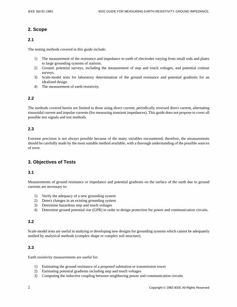
The testing methods covered in this guide include:
1) The measurement of the resistance and impedance to earth of electrodes varying from small rods and platesto large grounding systems of stations.
2) Ground. potential surveys, including the measurement of step and touch voltages, and potential contoursurveys.
3) Scale-model tests for laboratory determination of the ground resistance and potential gradients for anidealized design.
4) The measurement of earth resistivity.
2.2
The methods covered herein are limited to those using direct current, periodically reversed direct current, alternatingsinusoidal current and impulse currents (for measuring transient impedances). This guide does not propose to cover allpossible test signals and test methods.
2.3
Extreme precision is not always possible because of the many variables encountered; therefore, the measurementsshould be carefully made by the most suitable method available, with a thorough understanding of the possible sourcesof error.
3. Objectives of Tests
3.1
Measurements of ground resistance or impedance and potential gradients on the surface of the earth due to groundcurrents are necessary to:
1) Verify the adequacy of a new grounding system2) Detect changes in an existing grounding system3) Determine hazardous step and touch voltages4) Determine ground potential rise (GPR) in order to design protection for power and communication circuits.
3.2
Scale-model tests are useful in studying or developing new designs for grounding systems which cannot be adequatelystudied by analytical methods (complex shape or complex soil structure).
3.3
Earth resistivity measurements are useful for:
1) Estimating the ground resistance of a proposed substation or transmission tower2) Estimating potential gradients including step and touch voltages3) Computing the inductive coupling between neighboring power and communication circuits
2 Copyright © 1983 IEEE All Rights Reserved
AND EARTH SURFACE POTENTIALS OF A GROUND SYSTEM IEEE Std 81-1983
4) Designing cathodic protection systems5) Geological surveys
4. Definitions
Definitions of terms pertinent to the subject matter are listed here. Those approved or standardized by other bodies areused wherever possible.
Definitions as given herein apply specifically to the application of this guide. For additional definitions see ANSI/IEEEStd 100-1977, IEEE Standard Dictionary of Electrical and Electronics Terms.
ground: A conducting connection, whether intentional or accidental, by which an electric circuit or equipment isconnected to the earth, or to some conducting body of relatively large extent that serves in place of the earth.
NOTE — It is used for establishing and maintaining the potential of the earth (or of the conducting body) or approximately thatpotential, on conductors connected to it, and for conducting ground current to and from the earth (or the conductingbody).
grounded: A system, circuit, or apparatus referred to is provided with a ground.
ground-return circuit: A circuit in which the earth is utilized to complete the circuit.
ground current: Current flowing in the earth or in a grounding connection.
grounding conductor: The conductor that is used to establish a ground and that connects an equipment, device,wiring system, or another conductor (usually the neutral conductor) with the grounding electrode or electrodes.
grounding electrode: A conductor used to establish a ground.
grounding connection: A connection used in establishing a ground and consists of a grounding conductor, agrounding electrode and the earth (soil) that surrounds the electrode or some conductive body which serves instead ofthe earth.
ground grid: A system of grounding electrodes consisting of interconnected bare cables buried in the earth to providea common ground for electrical devices and metallic structures.
NOTE — It may be connected to auxiliary grounding electrodes to lower its resistance.
ground mat: A system of bare conductors, on or below the surface of the earth, connected to a ground or a ground gridto provide protection from dangerous touch voltages.
NOTE — Plates and gratings of suitable area are common forms of ground mats.
grounding system: Consists of all interconnected grounding connections in a specific area.
ground resistance (grounding electrode): The ohmic resistance between the grounding electrode and a remotegrounding electrode of zero resistance.
NOTE — By remote is meant at a distance such that the mutual resistance of the two electrodes is essentially zero.
mutual resistance of grounding electrodes: Equal to the voltage change in one of them produced by a change of oneampere of direct current in the other, and is expressed in ohms.
electric potential: The potential difference between the point and some equipotential surface, usually the surface ofthe earth, which is arbitrarily chosen as having zero potential (remote earth).
NOTE — A point which has a higher potential than a zero surface is said to have a positive potential; one having a lower potentialhas a negative potential.
equipotential line or contour: The locus of points having the same potential at a given time.
potential profile: A plot of potential as a function of distance along a specified path.
Copyright © 1983 IEEE All Rights Reserved 3
IEEE Std 81-1983 IEEE GUIDE FOR MEASURING EARTH RESISTIVITY, GROUND IMPEDANCE,
surface-potential gradient: The slope of a potential profile, the path of which intersects equipotential lines at rightangles.
touch voltage: The potential difference between a grounded metallic structure and a point on the earth's surfaceseparated by a distance equal to the normal maximum horizontal reach, approximately one meter.
step voltage: The potential difference between two points on the earth's surface, separated by a distance of one pace,that will be assumed to be one meter, in the direction of maximum potential gradient.
NOTE — This potential difference could be dangerous when current flows through the earth or material upon which a workman isstanding, particularly under fault conditions.
resistivity (material): A factor such that the conduction-current density is equal to the electric field in the materialdivided by the resistivity.
coupling: The association of two or more circuits or systems in such a way that power or signal information may betransferred from one to another.
NOTE — Coupling is described as close or loose. A close-coupled process has elements with small phase shift between specifiedvariables; close-coupled systems have large mutual effect shown mathematically by cross-products in the system matrix.
coupling capacitance: The association of two or more circuits with one another by means of capacitance mutual to thecircuits.
resistive coupling: The association of two or more circuits with one another by means of resistance mutual to thecircuits.
direct coupling: The association of two or more circuits by means of self-inductance, capacitance, resistance, or acombination of these that is common to the circuits.
inductive coupling (1) (communication circuits): The association of two or more circuits with one another by meansof inductance mutual to the circuits or the mutual inductance that associates the circuits.
NOTE — This term, when used without modifying words, is commonly used for coupling by means of mutual inductance,whereas coupling by means of self-inductance common to the circuits is called direct inductive coupling.
(2) (inductive coordination practice): The interrelation of neighboring electric supply and communication circuitsby electric or magnetic induction, or both.
effective resistivity: A factor such that the conduction current density is equal to the electric field in the materialdivided by the resistivity.
counterpoise (overhead lines) (lighting protection): A conductor or system of conductors, arranged beneath thetransmission line, located on, above or most frequently below the surface of the earth, and connected to the footings ofthe towers or poles supporting the line.
5. Safety Precautions While Making Ground Tests
5.1 Station Ground Tests
It should be strongly impressed on all test personnel that a lethal potential can exist between the station ground and aremote ground if a power-system fault involving the station ground occurs while ground tests are being made.
Since one of the objectives of tests on a station-ground system is to establish the location of remote earth for bothcurrent and potential electrodes, the leads to these electrodes must be treated as though a possible potential could existbetween test leads and any point on the station ground grid. Some idea of the magnitude of this possible potential maybe gained from the consideration that even in the larger stations the ground grid shall have an impedance in the orderof 0.05 Ω to 0.5Ω. Assuming for this example that the ground-fault current through the grid is in the order of 20 kA thepotential to remote earth (ground potential rise) will be in the order of 1.0 kV to 10 kV. For higher ground impedanceor greater fault currents, the rise of station-ground voltage may exceed 10 kV.
4 Copyright © 1983 IEEE All Rights Reserved
AND EARTH SURFACE POTENTIALS OF A GROUND SYSTEM IEEE Std 81-1983
The preceding discussion points to the necessity of caution when handling the test leads, and under no circumstancesshould the two hands or other parts of the body be allowed to complete the circuit between points of possible high-potential difference. It is true that the chances are remote that a station-ground fault will occur while test leads arebeing handled, but this possibility should not be discounted and therefore the use of insulating shoes, gloves, blankets,and other protection devices are recommended whenever measurements are carried out at an energized power station.
In all cases, safety procedures and practices adopted by the particular organization involved shall be followed.
5.2 Surge-Attester Ground Tests
These grounds fall in a special category because of the extremely high short-duration lightning currents carried bysurge-arrester grounds. These currents may be in excess of 50 000 A for surge currents, with a possibility of fault-system currents in the case of a defective surge arrester. An isolated surge arrester ground should never bedisconnected to be measured, since the base of the arrester can be elevated to the line potential. A surge-arrester groundcan be tested as long as precautions axe taken to minimize arrester discharge.
5.3 Small Isolated Ground Tests
Another precaution concerns possible high-potential gradients around the current electrode. If current is passed into aremotely located electrode, as in the fall-of-potential method, it is worthwhile to ensure against a curious person beingallowed near the current electrode while tests are in progress. Similarly, in rural areas grazing animals should not beallowed near the test current electrode.
6. General Considerations of the Problems Related to Measurements
6.1 Complexities
The measurements of earth resistivities, ground impedances, and potential gradients introduce a number ofcomplexities not encountered in other resistance, impedance, and potential measurements.
It may be necessary to make multiple measurements and to plot trends. Stray currents and other factors usuallyinterfere with the measurements.
With development and industrial growth adjacent to power substations, it becomes increasingly difficult to choose asuitable direction or locations for test probes to make a resistance test. Moreover, the connection of overhead groundwires, buried water pipes, cable sheaths, etc, all have the effect of physically distorting and enlarging the ground grid.
NOTE — Overhead ground wires may be insulated either deliberately or by clamp corrosion and therefore low-voltage tests maygive answers different from actual fault tests.
Ground impedance measurements should be made immediately after the ground grid has been installed to be certainthat there are no major omissions of grounded components normally connected into the ground grid. Futureinstallations such as water pipes, rail, etc will alter the values.
It should be noted, however, that the ground impedance will usually decrease as the earth settles to a uniformcompactness perhaps a year after installation.
6.2 Test Electrodes
The ground-impedance measurement methods described in the following sections require the use of current andvoltage test electrodes.
Copyright © 1983 IEEE All Rights Reserved 5
IEEE Std 81-1983 IEEE GUIDE FOR MEASURING EARTH RESISTIVITY, GROUND IMPEDANCE,
If the impedance measurement method used is the two- or three-point method, the impedance of the test electrodesshould be either negligible with respect to that of the ground being tested (two-point method) or of the same order ofmagnitude as the ground being tested (three-point method). Otherwise, incorrect results may be obtained.
Obviously, these restrictions limit the use of such methods to grounds of relatively small extent such as residentialswimming pools and small low-voltage distribution substation grounds.
In the case of impedance measurements using the fall-of-potential method, the requirements of the test electrodes arenot so critical.
Theoretically the ground resistances of the test electrodes do not influence the measurements since these are taken intoconsideration by the method of measurement. In practice, however, the resistance values should not exceed amaximum value beyond which there is insufficient test current in the measuring instrument. By insufficient test currentis meant:
1) Current lower than the instrument sensitivity, or2) Current in the order of magnitude of the stray currents in the earth3) Or both (1) and (2)
In case (1), the only corrective action available at the site of measurement is to increase the test current. This can bedone by either increasing the voltage of the power supply or by decreasing the test electrode resistances. Increasing thepower supply voltage is not always possible especially with hand-driven generators incorporated in the measuringinstrument. When this solution is practical, care must be taken to avoid dangerous potentials of the electrodes and testleads. A maximum of 100 V is considered safe if special precautions (such as use of insulating gloves or shoes) aretaken.
Often the most effective way of increasing the test current is to decrease the current electrode resistance. This can bedone by driving the rod deeper into the soil, pouring water around the rod, or by driving additional rods andinterconnecting them in parallel. The addition of salt to the water poured around the test electrodes is of very littlevalue; the moisture is the main requirement.
As a general rule the resistance values of the current and potential electrodes should meet the requirements of theinstruments used. With commercial instruments, a potential electrode resistance of 1000 Ω may be used. Somemanufacturers claim that their instrument will permit 10 000 Ω in the potential electrode.
The current electrode resistance should usually be less than 500 Ω. This resistance value is a function of the voltagegenerated by the power supply and the desired test current. The ratio of the generated voltage to the current electroderesistance determines the test current flowing in the current-indicating element of the instrument being used. As a ruleof thumb the ratio between the current electrode resistance and the ground resistance being tested should never exceed1000 to 1, preferably 100 to 1 or less.
In case (2), when dc tests are being made, the test current must be increased to overcome the interfering effects of straydc earth currents. When tests with ac or periodically reversed dc signals axe being made, the frequency of the testsignal may be set to a frequency not present in the stray currents.
6.3 Stray Direct Currents
Conduction of electricity in the soil is electrolytic and direct current results in chemical action and polarizationpotential difference. Direct potentials are produced between various types of soil and between soil and metal bygalvanic action. Galvanic potentials, polarization, and, if present, stray direct currents may seriously interfere withdirect-current measurements. Therefore, periodically reversed direct current or sometimes a regularly pulsed current isused in making measurements. However, when using periodically reversed direct current for resistance measurements
6 Copyright © 1983 IEEE All Rights Reserved
AND EARTH SURFACE POTENTIALS OF A GROUND SYSTEM IEEE Std 81-1983
the resulting values will be fairly close, but they may not be accurate for alternating-current applications. Caution mustbe exercised in areas subject to solar-induced currents (quasi-dc).
6.4 Stray Alternating Currents
Stray alternating currents in the earth, in the grounding system under test, and in the test electrodes present anadditional complication. The effects of stray alternating current may be mitigated in ground resistance measurementsby utilizing a frequency that is not present in the stray current. Most measuring devices use frequencies within a rangeof 50 Hz to 100 Hz. The use of filters or narrow band measuring instruments, or both, is often required to overcome theeffects of stray alternating currents.
6.5 Reactive Component of Impedance of a Large Grounding System
The impedance of a large grounding system may be extremely low (for example, 0.010 Ω) but it may have a significantquadrature component [B23]1. Certain precautions should be taken when measuring the 60 Hz impedance of a largegrounding system. For such measurements the test device should be operated at an approximate system frequency of60 Hz, but the test frequency should be slightly above or below 60 Hz, using a minimum of 50 A for the most accurateresults and to avoid 60 Hz ground currents. Part II of this guide2, Special Measurements, will cover impedancemeasurements of large grounding systems.
6.6 Coupling Between Test Leads
The effect of coupling between the test leads becomes important when measuring low values of ground impedance.Any voltage produced in the potential lead due to coupling from current flowing in the current lead is directly additiveto the desired measured voltage and produces a measurement error. Since the 60 Hz inductive coupling between twoparallel test leads may be as high as 0.1 Ω/100 m, the error can be appreciable. Low ground impedance usually is foundwith a large area ground, which requires long test leads to reach remote earth.
Conversely, a small area ground usually has fairly high ground impedance and requires shorter test leads to reachremote earth. Thus the effects of coupling can be expected to be worse on measurements of large area, low impedancegrounds. As a rule of thumb test lead coupling is usually negligible on measurements of grounds of 10 Ω or greater, isalmost always important on measurements of 1 Ω or less, and should be considered in the range between 1 and 10 Ω.
Test lead coupling may be minimized by appropriately routing the potential and current leads. When test leadcouplings are anticipated, the potential and current leads should be placed at the maximum feasible angle.
6.7 Buried Metallic Objects
Partially or completely buried objects such as rails, water, or other industrial metallic pipes will considerably influencethe measurement results [B9], [B36].
In earth-resistivity tests a sharp drop in the measured value is often caused by the presence of a metallic object buriedclose to the test location. The magnitude and extent of the drop gives an idea of the importance and depth of the buriedmaterial. The measured resistance of a ground electrode located close to a buried metallic object can be significantlylower than its value if the additional buried metal objects were not present. However, the importance of the effect ofburied metallic structures should not be minimized in determining the effective GPR for communication protectivepurpose. Earth potential contours are distorted and gradients are increased when measured above buried metallicobjects.
1The numbers in brackets correspond to those of the Bibliography listed in Appendix D of this guide.2Part II of this guide has not been completed at this time.
Copyright © 1983 IEEE All Rights Reserved 7
IEEE Std 81-1983 IEEE GUIDE FOR MEASURING EARTH RESISTIVITY, GROUND IMPEDANCE,
Wherever the presence of buried metallic structures is suspected in the area where soil resistivity measurements are tobe taken and the location of these structures is known, the influence of these structures on the soil resistivitymeasurement results can be minimized by aligning the test probes in a direction perpendicular to the routing of thesestructures. Also the location of the test probes should be as far as possible from the buried structures.
7. Earth Resistivity
7.1 General
The techniques for measuring soil resistivity are essentially the same whatever the purpose of the measurement.However, the interpretation of the recorded data can vary considerably, especially where soils with non-uniformresistivities are encountered. The added complexity caused by nonuniform soils is common, and in only a few casesare the soil resistivities constant with increasing depth.
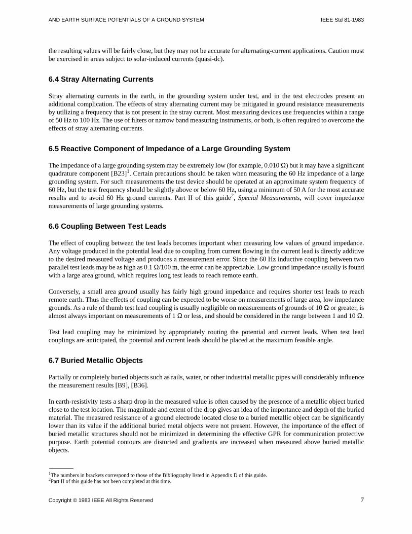
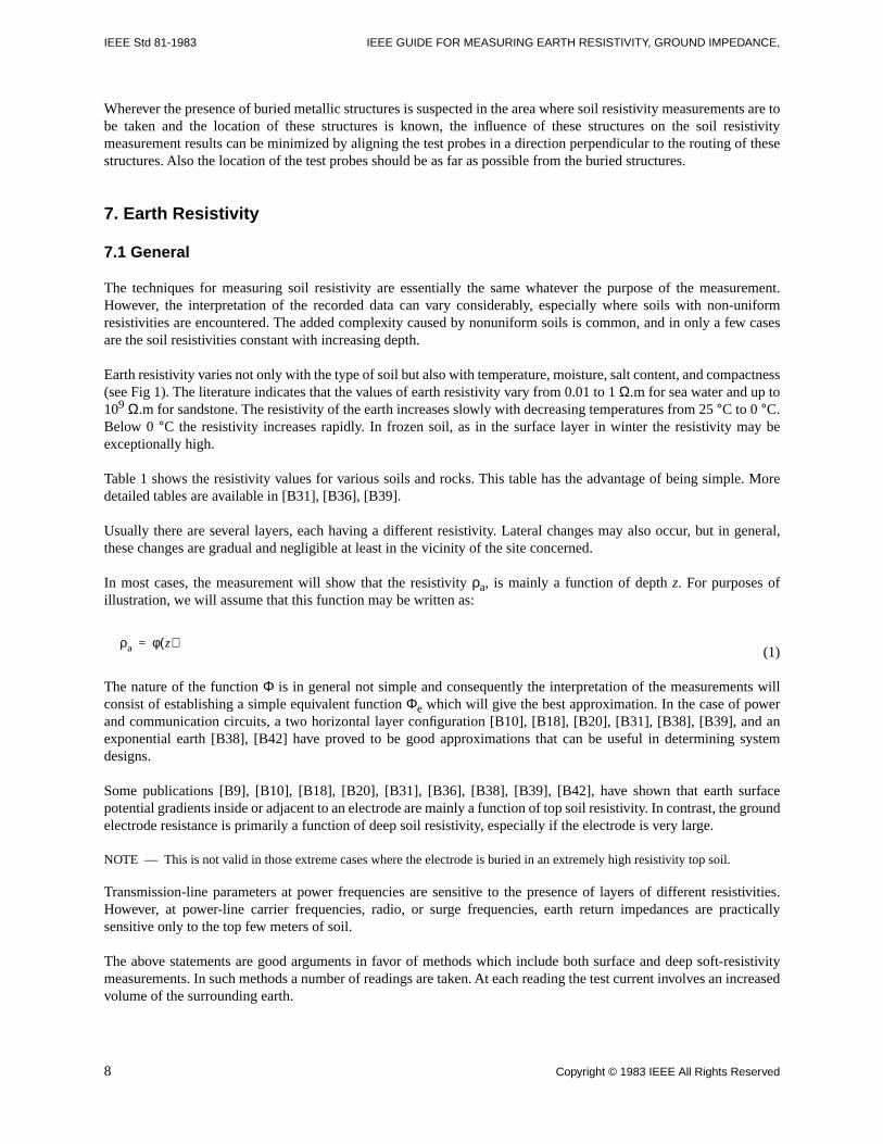
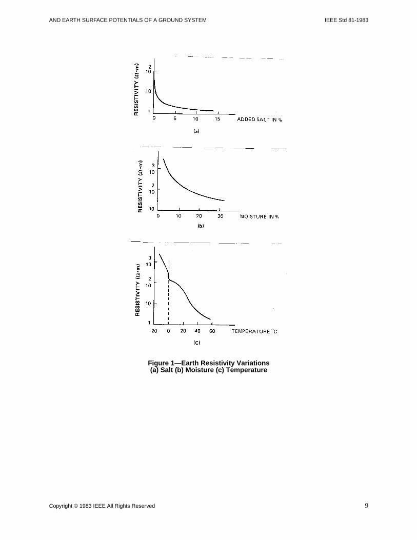
Earth resistivity varies not only with the type of soil but also with temperature, moisture, salt content, and compactness(see Fig 1). The literature indicates that the values of earth resistivity vary from 0.01 to 1 Ω.m for sea water and up to109 Ω.m for sandstone. The resistivity of the earth increases slowly with decreasing temperatures from 25 °C to 0 °C.Below 0 °C the resistivity increases rapidly. In frozen soil, as in the surface layer in winter the resistivity may beexceptionally high.
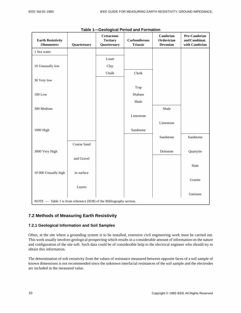
Table 1 shows the resistivity values for various soils and rocks. This table has the advantage of being simple. Moredetailed tables are available in [B31], [B36], [B39].
Usually there are several layers, each having a different resistivity. Lateral changes may also occur, but in general,these changes are gradual and negligible at least in the vicinity of the site concerned.
In most cases, the measurement will show that the resistivity ρa, is mainly a function of depth z. For purposes ofillustration, we will assume that this function may be written as:
(1)
The nature of the function Φ is in general not simple and consequently the interpretation of the measurements willconsist of establishing a simple equivalent function Φe which will give the best approximation. In the case of powerand communication circuits, a two horizontal layer configuration [B10], [B18], [B20], [B31], [B38], [B39], and anexponential earth [B38], [B42] have proved to be good approximations that can be useful in determining systemdesigns.
Some publications [B9], [B10], [B18], [B20], [B31], [B36], [B38], [B39], [B42], have shown that earth surfacepotential gradients inside or adjacent to an electrode are mainly a function of top soil resistivity. In contrast, the groundelectrode resistance is primarily a function of deep soil resistivity, especially if the electrode is very large.
NOTE — This is not valid in those extreme cases where the electrode is buried in an extremely high resistivity top soil.
Transmission-line parameters at power frequencies are sensitive to the presence of layers of different resistivities.However, at power-line carrier frequencies, radio, or surge frequencies, earth return impedances are practicallysensitive only to the top few meters of soil.
The above statements are good arguments in favor of methods which include both surface and deep soft-resistivitymeasurements. In such methods a number of readings are taken. At each reading the test current involves an increasedvolume of the surrounding earth.
ρa φ z( )=
8 Copyright © 1983 IEEE All Rights Reserved
AND EARTH SURFACE POTENTIALS OF A GROUND SYSTEM IEEE Std 81-1983
Figure 1—Earth Resistivity Variations (a) Salt (b) Moisture (c) Temperature
Copyright © 1983 IEEE All Rights Reserved 9
IEEE Std 81-1983 IEEE GUIDE FOR MEASURING EARTH RESISTIVITY, GROUND IMPEDANCE,
Table 1—Geological Period and Formation
7.2 Methods of Measuring Earth Resistivity
7.2.1 Geological Information and Soil Samples
Often, at the site where a grounding system is to be installed, extensive civil engineering work must be carried out.This work usually involves geological prospecting which results in a considerable amount of information on the natureand configuration of the site soft. Such data could be of considerable help to the electrical engineer who should try toobtain this information.
The determination of soft resistivity from the values of resistance measured between opposite faces of a soil sample ofknown dimensions is not recommended since the unknown interfacial resistances of the soil sample and the electrodesare included in the measured value.
Earth Resistivity Ohmmeters Quarternary
Cretaceous Tertiary
QuarternaryCarboniferous
Triassic
Cambrian Ordovician Devonian
Pre-Cambrian and Combinat. with Cambrian
1 Sea water
Loam
10 Unusually low Clay
Chalk Chalk
30 Very low
Trap
100 Low Diabase
Shale
300 Medium Shale
Limestone
Limestone
1000 High Sandstone
Sandstone Sandstone
Coarse Sand
3000 Very High Dolomite Quartyite
and Gravel
Slate
10 000 Unusally high in surface
Granite
Layers
Gneisses
NOTE — Table 1 is from reference [B38] of the Bibliography section.
10 Copyright © 1983 IEEE All Rights Reserved
AND EARTH SURFACE POTENTIALS OF A GROUND SYSTEM IEEE Std 81-1983
A more accurate determination is possible if a four-terminal resistance measurement of the soil sample is made. Thepotential terminals should be small, relative to the sample cross-section, and located sufficiently distant from thecurrent terminals to assure near-uniform current distribution across the sample. A distance equal to the larger cross-section dimension is usually adequate for the purpose of the determination.
It is difficult, and in some cases impossible, to obtain a useful approximation of soil resistivity from resistivitymeasurements on samples. This is due to the difficulty of obtaining representative, homogeneous soil samples, and induplicating the original soil compaction and moisture content in the test cell.
7.2.2 Variation of Depth Method
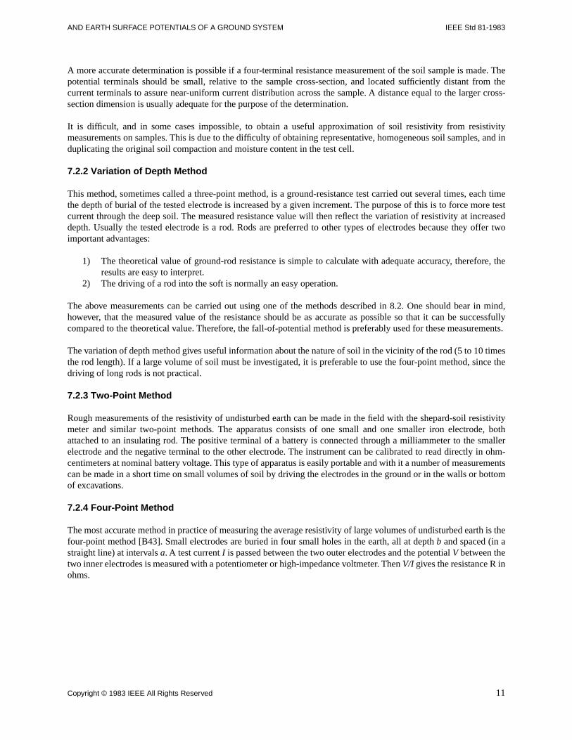
This method, sometimes called a three-point method, is a ground-resistance test carried out several times, each timethe depth of burial of the tested electrode is increased by a given increment. The purpose of this is to force more testcurrent through the deep soil. The measured resistance value will then reflect the variation of resistivity at increaseddepth. Usually the tested electrode is a rod. Rods are preferred to other types of electrodes because they offer twoimportant advantages:
1) The theoretical value of ground-rod resistance is simple to calculate with adequate accuracy, therefore, theresults are easy to interpret.
2) The driving of a rod into the soft is normally an easy operation.
The above measurements can be carried out using one of the methods described in 8.2. One should bear in mind,however, that the measured value of the resistance should be as accurate as possible so that it can be successfullycompared to the theoretical value. Therefore, the fall-of-potential method is preferably used for these measurements.
The variation of depth method gives useful information about the nature of soil in the vicinity of the rod (5 to 10 timesthe rod length). If a large volume of soil must be investigated, it is preferable to use the four-point method, since thedriving of long rods is not practical.
7.2.3 Two-Point Method
Rough measurements of the resistivity of undisturbed earth can be made in the field with the shepard-soil resistivitymeter and similar two-point methods. The apparatus consists of one small and one smaller iron electrode, bothattached to an insulating rod. The positive terminal of a battery is connected through a milliammeter to the smallerelectrode and the negative terminal to the other electrode. The instrument can be calibrated to read directly in ohm-centimeters at nominal battery voltage. This type of apparatus is easily portable and with it a number of measurementscan be made in a short time on small volumes of soil by driving the electrodes in the ground or in the walls or bottomof excavations.
7.2.4 Four-Point Method
The most accurate method in practice of measuring the average resistivity of large volumes of undisturbed earth is thefour-point method [B43]. Small electrodes are buried in four small holes in the earth, all at depth b and spaced (in astraight line) at intervals a. A test current I is passed between the two outer electrodes and the potential V between thetwo inner electrodes is measured with a potentiometer or high-impedance voltmeter. Then V/I gives the resistance R inohms.
Copyright © 1983 IEEE All Rights Reserved 11
IEEE Std 81-1983 IEEE GUIDE FOR MEASURING EARTH RESISTIVITY, GROUND IMPEDANCE,
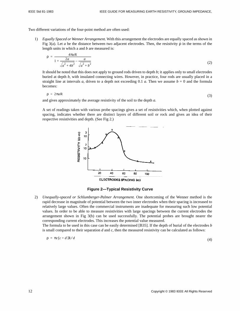
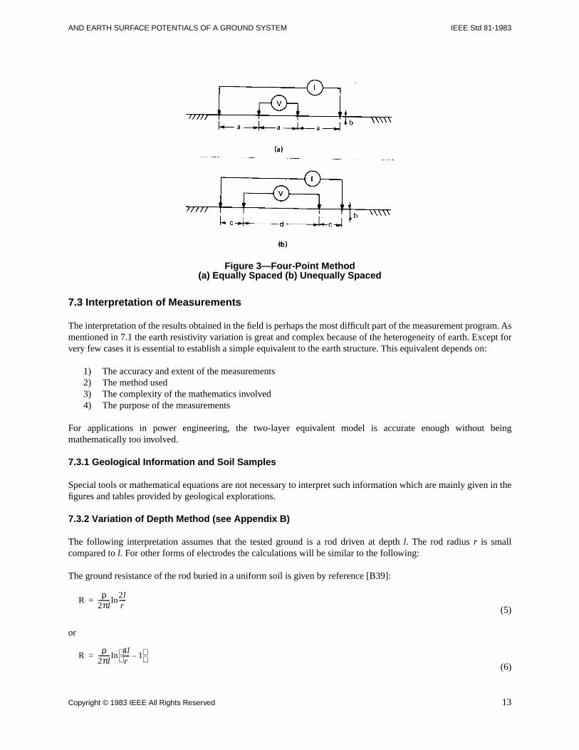
Two different variations of the four-point method are often used:
1) Equally Spaced or Wenner Arrangement. With this arrangement the electrodes are equally spaced as shown inFig 3(a). Let a be the distance between two adjacent electrodes. Then, the resistivity ρ in the terms of thelength units in which a and b are measured is:
(2)
It should be noted that this does not apply to ground rods driven to depth b; it applies only to small electrodesburied at depth b, with insulated connecting wires. However, in practice, four rods are usually placed in astraight line at intervals a, driven to a depth not exceeding 0.1 a. Then we assume b = 0 and the formulabecomes:
(3)and gives approximately the average resistivity of the soil to the depth a.
A set of readings taken with various probe spacings gives a set of resistivities which, when plotted againstspacing, indicates whether there are distinct layers of different soil or rock and gives an idea of theirrespective resistivities and depth. (See Fig 2.)
Figure 2—Typical Resistivity Curve
2) Unequally-spaced or Schlumberger-Palmer Arrangement. One shortcoming of the Wenner method is therapid decrease in magnitude of potential between the two inner electrodes when their spacing is increased torelatively large values. Often the commercial instruments are inadequate for measuring such low potentialvalues. In order to be able to measure resistivities with large spacings between the current electrodes thearrangement shown in Fig 3(b) can be used successfully. The potential probes are brought nearer thecorresponding current electrodes. This increases the potential value measured. The formula to be used in this case can be easily determined [B35]. If the depth of burial of the electrodes bis small compared to their separation d and c, then the measured resistivity can be calculated as follows:
(4)
ρ 4πaR
1 2a
a2
4b2
+------------------------- a
a2
b2
+---------------------–+
--------------------------------------------------------------=
ρ 2πaR=
ρ πc c d+( )R d⁄=
12 Copyright © 1983 IEEE All Rights Reserved
AND EARTH SURFACE POTENTIALS OF A GROUND SYSTEM IEEE Std 81-1983
Figure 3—Four-Point Method (a) Equally Spaced (b) Unequally Spaced
7.3 Interpretation of Measurements
The interpretation of the results obtained in the field is perhaps the most difficult part of the measurement program. Asmentioned in 7.1 the earth resistivity variation is great and complex because of the heterogeneity of earth. Except forvery few cases it is essential to establish a simple equivalent to the earth structure. This equivalent depends on:
1) The accuracy and extent of the measurements2) The method used3) The complexity of the mathematics involved4) The purpose of the measurements
For applications in power engineering, the two-layer equivalent model is accurate enough without beingmathematically too involved.
7.3.1 Geological Information and Soil Samples
Special tools or mathematical equations are not necessary to interpret such information which are mainly given in thefigures and tables provided by geological explorations.
7.3.2 Variation of Depth Method (see Appendix B)
The following interpretation assumes that the tested ground is a rod driven at depth l. The rod radius r is smallcompared to l. For other forms of electrodes the calculations will be similar to the following:
The ground resistance of the rod buried in a uniform soil is given by reference [B39]:
(5)
or
(6)
Rρ
2πl--------In
2lr-----=
Rρ
2πl--------In 4l
r----- 1–
=
Copyright © 1983 IEEE All Rights Reserved 13
IEEE Std 81-1983 IEEE GUIDE FOR MEASURING EARTH RESISTIVITY, GROUND IMPEDANCE,
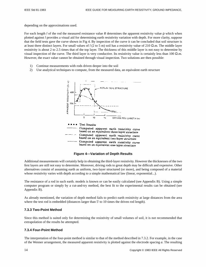
depending on the approximations used.
For each length l of the rod the measured resistance value R determines the apparent resistivity value ρ which whenplotted against l provides a visual aid for determining earth resistivity variation with depth. For more clarity, supposethat the field tests gave the curve shown in Fig 4. By inspection of the curve it can be concluded that soil structure isat least three distinct layers. For small values of l (2 to 5 m) soil has a resistivity value of 210 Ω.m. The middle layerresistivity is about 2 to 2.5 times that of the top layer. The thickness of this middle layer is not easy to determine byvisual inspection of the curve. The third layer is very conductive. Its resistivity value is certainly less than 100 Ω.m.However, the exact value cannot be obtained through visual inspection. Two solutions are then possible:
1) Continue measurements with rods driven deeper into the soil2) Use analytical techniques to compute, from the measured data, an equivalent earth structure
Figure 4—Variation of Depth Results
Additional measurements will certainly help in obtaining the third-layer resistivity. However the thicknesses of the twofirst layers are still not easy to determine. Moreover, driving rods to great depth may be difficult and expensive. Otheralternatives consist of assuming earth as uniform, two-layer structured (or more), and being composed of a materialwhose resistivity varies with depth according to a simple mathematical law (linear, exponential...).
The resistance of a rod in such earth. models is known or can be easily calculated (see Appendix B). Using a simplecomputer program or simply by a cut-and-try method, the best fit to the experimental results can be obtained (seeAppendix B).
As already mentioned, the variation of depth method fails to predict earth resistivity at large distances from the areawhere the test rod is embedded (distances larger than 5' to 10 times the driven rod length).
7.3.3 Two-Point Method
Since this method is suited only for determining the resistivity of small volumes of soil, it is not recommended thatextrapolation of the results be attempted.
7.3.4 Four-Point Method
The interpretation of the four-point method is similar to that of the method described in 7.3.2. For example, in the caseof the Wenner arrangement, the measured apparent resistivity is plotted against the electrode spacing a. The resulting
14 Copyright © 1983 IEEE All Rights Reserved
AND EARTH SURFACE POTENTIALS OF A GROUND SYSTEM IEEE Std 81-1983
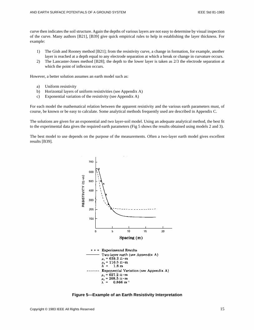
curve then indicates the soil structure. Again the depths of various layers are not easy to determine by visual inspectionof the curve. Many authors [B21], [B39] give quick empirical rules to help in establishing the layer thickness. Forexample:
1) The Gish and Rooney method [B21]; from the resistivity curve, a change in formation, for example, anotherlayer is reached at a depth equal to any electrode separation at which a break or change in curvature occurs.
2) The Lancaster-Jones method [B28]; the depth to the lower layer is taken as 2/3 the electrode separation atwhich the point of inflexion occurs.
However, a better solution assumes an earth model such as:
a) Uniform resistivityb) Horizontal layers of uniform resistivities (see Appendix A)c) Exponential variation of the resistivity (see Appendix A)
For each model the mathematical relation between the apparent resistivity and the various earth parameters must, ofcourse, be known or be easy to calculate. Some analytical methods frequently used are described in Appendix C.
The solutions are given for an exponential and two layer-soil model. Using an adequate analytical method, the best fitto the experimental data gives the required earth parameters (Fig 5 shows the results obtained using models 2 and 3).
The best model to use depends on the purpose of the measurements. Often a two-layer earth model gives excellentresults [B39].
Figure 5—Example of an Earth Resistivity Interpretation
Copyright © 1983 IEEE All Rights Reserved 15
IEEE Std 81-1983 IEEE GUIDE FOR MEASURING EARTH RESISTIVITY, GROUND IMPEDANCE,
7.4 Instrumentation
7.4.1 Two-Point Method
Shepard-soil resistivity meter or similar (see 7.2 for complete description).
7.4.2 Four-Point or Variation-of-Depth Methods
One of the following instruments can be used (see Section 12).
1) Power supply with ammeter and high impedance voltmeter2) Ratio ohmmeter3) Double-balance bridge4) Single-balance transformer5) Induced-polarization receiver and transmitter.
Dependent on the mode of connection and terminals used these instruments can either measure ground resistance orearth resistivity.
In inductive coordination work, spacings up to 1000 m often have been used. For these long spacings, the resistance isof the order of a few hundredths of an ohm, and a sensitive direct-current potentiometer with a battery supply as highas 180 V may be required. For the shorter spacings, the four-terminal instruments shown in Figs 14, 15, and 16 areconvenient and adequate. For some instruments correction may be required for the potential probe resistances; in suchcases correction factors can usually be obtained from the supplier of the instrument.
The induced polarization transmitter is normally rated at a few hundred watts. However, for great spacings orextremely high top-soil resistivities, units rated at more than 1000 W may be necessary
8. Ground Impedance
8.1 General
Connections to earth in general are complex impedances, having resistive, capacitive, and inductive components, all ofwhich affect their current-carrying capabilities. The resistance of the connection is of particular interest to thoseconcerned with power frequencies because it is affected by the resistivity of the earth in the area of the connection. Thecapacitance and inductance values are of interest to those concerned with higher frequencies, such as are associatedwith radio communications and lightning.
Ground-impedance measurements are made:
1) To determine the actual impedance of the ground connections2) As a check on calculations3) (3) To determine (a) the rise in ground potential and its variation throughout an area, that results from ground
fault current in a power system, (b) the suitability of a grounding connection for lightning protection, and thesuitability of a grounding connection for radio-frequency transmission at a transmitter
4) To obtain data necessary for the design of protection for buildings, the equipment therein, and any personnelthat may be involved
Ground connections of all power and communication systems should be studied to determine the variation in groundpotential that can be encountered during ground-fault conditions so as to ensure personnel safety, adequacy ofinsulation, and continuity of service.
16 Copyright © 1983 IEEE All Rights Reserved
AND EARTH SURFACE POTENTIALS OF A GROUND SYSTEM IEEE Std 81-1983
8.1.1 Characteristics
The characteristics of a grounding connection vary with the composition and physical state of the soil as well as withthe extent and configuration of the buried electrode. Earth in any given locality is composed of various combinationsof dry earth, swampy ground, gravel, slate, sandstone, or other natural materials of widely varying resistivity. It maybe relatively homogeneous over a large area, or it may be effectively saucered in granite, sand, or other matter havinga high resistivity and thus be practically insulated from the surrounding area. Consequently, the characteristics of agrounding connection (ohmic resistance) vary with the seasons, which affect temperature, moisture content, andcompactness of the soil.
Calculations and experience show that, in a given soil, the effectiveness of a ground grid is dependent largely upon theoverall size of the ground grid. The addition of buried conductors and driven rods within an enclosure also aidsomewhat in reducing the ground impedance. This reduction diminishes with the addition of each successiveconductor or rod. A good method for reducing the ground resistance of a transmission-line tower or mast is to installradial counterpoises.
After the installation of a substation or other grounded structure, the settling of the earth with annual cyclical weatherchanges tends to reduce the ground impedance substantially during the first year or two.
The impedance of a grounding electrode is usually measured in terms of resistance because the reactance is generallynegligible with respect to the resistive component. (This is not applicable for large grounding structures withimpedance values below 0.5 Ω, and for grounds subject to surge or impulse currents.) This resistance will not usuallyvary greatly from year to year after the first year or two following the burial of the ground grid. Although the groundgrid may be buried only half a meter below the surface, the variation of the resistance for larger stations seems to-bearlittle relationship to the variation of the resistivity at the burial level. This is especially true for grids equipped withlong driven rods in contact with the deep soil which normally is not influenced by weather conditions (temperature andmoisture changes which result in top layer resistivity variations). However, this will not be true for grids buried over ahigh resistivity stratum, or simply for small electrodes (having an area of less than 50 m2).
Although the above statements appear to be contradictory they are, nevertheless, true. Records which have been keptof large area ground grids over a period of eighteen years show little variation in the measured value of resistance,whereas, resistivity measurements in the same area show wide variations (as much as 17 to 1 at shallow depths). Itshould be recognized that the resistance of a grounding connection with a small number of driven rods may vary moreclosely with that indicated by resistivity measurements. This indicates that the resistance of large area ground grids isproportional to resistivity measurements made for greater depths where less variation is encountered.
Some of the ground-fault current from a transmission line fault to a substation ground grid tends to follow thetransmission line. Depth of mean current path is directly proportional to the square root of the earth resistivity andinversely proportional to the square root of the frequency. Thus resistance tends to increase the cross-sectional area ofthe current path, whereas inductance tends to decrease it and to tie more closely to the transmission line. This tendencywill also affect the pattern of the current path away from the electrode.
8.1.2 Theoretical Value of Ground Resistance
Calculated or theoretical values of the resistance of an electrode to remote earth can vary considerably from themeasured value because of the following factors:
1) Adequacy of the analytical equations used in the resistance calculations.2) Conditions of the soil at the time the measurement is made. Earth resistivities being different from those
assumed in the calculations.3) Inaccurate or insufficient extent of the resistivity survey; for example, number and dispersal of tests, probe
spacings, and inadequacy of the instrumentation used.4) Presence in the soil of adjacent metallic buried structures and ground wires which may divert a substantial
amount of the test current.
Copyright © 1983 IEEE All Rights Reserved 17
IEEE Std 81-1983 IEEE GUIDE FOR MEASURING EARTH RESISTIVITY, GROUND IMPEDANCE,
In order to decrease the sources of error in establishing the relationship between earth resistivity and ground resistanceit is advisable to take resistivity and resistance measurements under similar weather and moisture conditions.
If the measured values are used as data for the design of a grounding electrode, it is recommended that themeasurements be carried out under various weather conditions. This will help the designer in establishing the mostrestrictive or limiting case, especially for small grounds which are influenced by seasonal changes in weather.
8.2 Methods of Measuring Ground Impedance
8.2.1 General
In this section only general methods are covered [B6], [B8], [B12], [B31], [B30]. For the instrumentation availablerefer to Section 12. While in this section the ohmic value is called resistance, it should be remembered that there is areactive component that should be taken into account when the ohmic value of the ground under test is less than 0.5 Ω,and the ground is of a relatively large extent. This reactive component has little effect in grounds with an impedancehigher than 1 Ω. The resistance of a ground electrode usually is determined with alternating or periodically reversedcurrent to avoid possible polarization effects when using direct current. The frequency of this alternating currentshould be near the power frequency.
8.2.1.1 Two-Point Method (Ammeter-Volt-meter Method)
In this method the total resistance of the unknown and an auxiliary ground is measured. The resistance of the auxiliaryground is presumed to be negligible in comparison with the resistance of the unknown ground, and the measured valuein ohms is called the resistance of the unknown ground.
The usual application of this method is to determine the resistance of a single rod-driven ground near a residence thatalso has a common municipal water supply system that uses metal pipe without insulating joints. The water pipe is theauxiliary ground and its ground resistance is assumed to be in the order of 1 Ω and must be low in relation to thepermissible driven ground maximum resistance which is usually in the order of 25 Ω.
Obviously, this method is subject to large errors for low-valued driven grounds but is very useful and adequate wherea go, no-go, type of test is all that is required.
8.2.1.2 Three-Point Method
This method involves the use of two test electrodes with the resistances of the test electrodes designated r2 and r3 andwith the electrode to be measured designated r1. The resistance between each pair of electrodes is measured anddesignated r12, r13, and r23,
where
r12 = r1 + r2 etc. Solving the simultaneous equations, it follows that:
(7)
Therefore, by measuring the series resistance of each pair of ground electrodes and substituting the resistance valuesin the equation, the value of r1 may be established. If the two test electrodes are of materially higher resistance than theelectrode under test, the errors in the individual measurements will be greatly magnified in the final result. For themeasurement, the electrodes must be at some distance from each other; otherwise absurdities may arise in thecalculations, such as zero or even negative resistance. In measuring the resistance of a single-driven electrode thedistance between the three separate ground electrodes should be at least 5 m with a preferable spacing of 10 m or more.For larger area grounding systems, which are presumably of lower resistances, spacings in the order of the dimensions
r1
r12( ) r23( ) r13( )+–
2-------------------------------------------------=
18 Copyright © 1983 IEEE All Rights Reserved
AND EARTH SURFACE POTENTIALS OF A GROUND SYSTEM IEEE Std 81-1983
of the grounding systems are required as a minimum. This method becomes awkward for large substations, and someform of the fall-of-potential method is preferred, if high accuracy is required.
8.2.1.3 Ratio Method
In this method the resistance of the electrode under test is compared with a known resistance, usually by using thesame electrode configuration, as in the fall-of-potential method. Since this is a comparison method the ohm readingsare independent of the test current magnitude if the test current is high enough to give adequate sensitivity.
8.2.1.4 Staged Fault Tests
Staged high-current tests may be required for those cases where specific information is desired on a particulargrounding installation. Also, a ground impedance determination can be obtained as auxiliary information at the time ofactual ground faults by utilizing an oscillograph or one element of the automatic station oscillograph.
In either case the instrumentation is the same. The object is to record the voltage between selected points on one ormore oscillograph elements. The voltages to be recorded will probably be of such great magnitude that potential step-down transformers will be required. The maximum voltages that can be expected and thus the ratios of the potentialtransformers required may be determined in advance of the staged tests by using the fall-of-potential method atpractical values of test current.
Another important consideration is the calibration of the oscillograph circuit, which is composed of a potentialtransformer with a possible high resistance in the primary. This resistance is composed of the remote potential groundin series with a long lead. A satisfactory calibration of the deflection of the oscillograph element may be made byinserting a measured voltage in the primary circuit in series with the lead and the remote potential ground as usedduring the test.
The location of the acutal points to be measured is dependent on the information desired; but in all cases due allowancemust be made for coupling between test circuits, as given in 6.5.
8.2.1.5 Fall-of-Potential Method
This method has several variations and is applicable to all types of ground impedance measurements. As mentioned in6.5, the impedance of a large grounding system may have an appreciable reactive component when the impedance isless than 0.5 Ω, therefore, the measured value is an impedance and should be so considered although the terminologyoften used is resistance.
The method involves passing a current into the electrode to be measured and noting the influence of this current interms of voltage between the ground under test and a test potential electrode.
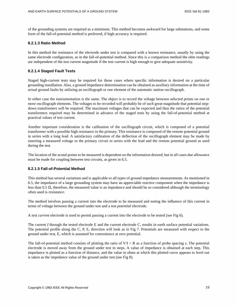
A test current electrode is used to permit passing a current into the electrode to be tested (see Fig 6).
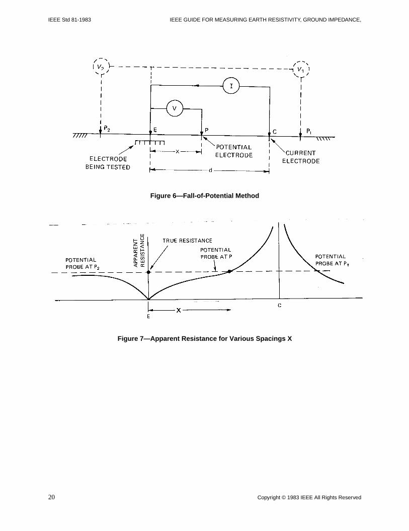
The current I through the tested electrode E and the current electrode C, results in earth surface potential variations.The potential profile along the C, P, E, direction will look as in Fig 7. Potentials are measured with respect to theground under test, E, which is assumed for convenience at zero potential.
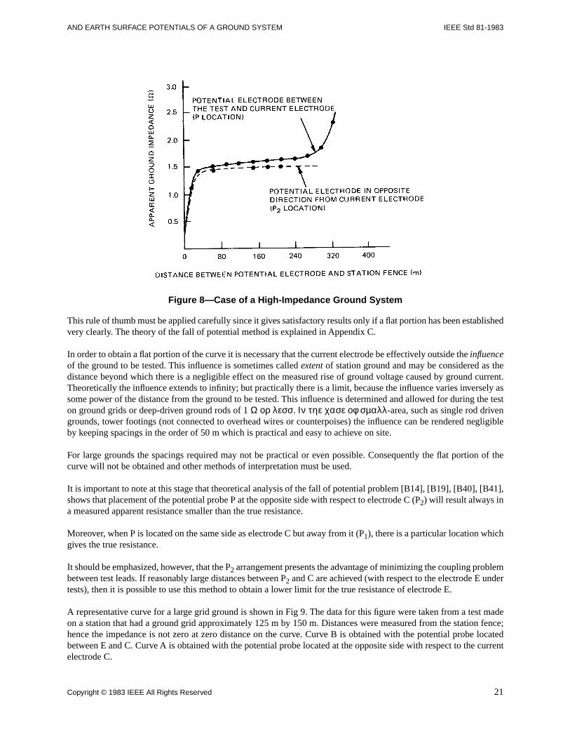
The fall-of-potential method consists of plotting the ratio of V/I = R as a function of probe spacing x. The potentialelectrode is moved away from the ground under test in steps. A value of impedance is obtained at each step. Thisimpedance is plotted as a function of distance, and the value in ohms at which this plotted curve appears to level outis taken as the impedance value of the ground under test (see Fig 8).
Copyright © 1983 IEEE All Rights Reserved 19
IEEE Std 81-1983 IEEE GUIDE FOR MEASURING EARTH RESISTIVITY, GROUND IMPEDANCE,
Figure 6—Fall-of-Potential Method
Figure 7—Apparent Resistance for Various Spacings X
20 Copyright © 1983 IEEE All Rights Reserved
AND EARTH SURFACE POTENTIALS OF A GROUND SYSTEM IEEE Std 81-1983
Figure 8—Case of a High-Impedance Ground System
This rule of thumb must be applied carefully since it gives satisfactory results only if a flat portion has been establishedvery clearly. The theory of the fall of potential method is explained in Appendix C.
In order to obtain a flat portion of the curve it is necessary that the current electrode be effectively outside the influenceof the ground to be tested. This influence is sometimes called extent of station ground and may be considered as thedistance beyond which there is a negligible effect on the measured rise of ground voltage caused by ground current.Theoretically the influence extends to infinity; but practically there is a limit, because the influence varies inversely assome power of the distance from the ground to be tested. This influence is determined and allowed for during the teston ground grids or deep-driven ground rods of 1 Ω ορ λεσσ. Ιν τηε χασε οφ σµαλλ-area, such as single rod drivengrounds, tower footings (not connected to overhead wires or counterpoises) the influence can be rendered negligibleby keeping spacings in the order of 50 m which is practical and easy to achieve on site.
For large grounds the spacings required may not be practical or even possible. Consequently the flat portion of thecurve will not be obtained and other methods of interpretation must be used.
It is important to note at this stage that theoretical analysis of the fall of potential problem [B14], [B19], [B40], [B41],shows that placement of the potential probe P at the opposite side with respect to electrode C (P2) will result always ina measured apparent resistance smaller than the true resistance.
Moreover, when P is located on the same side as electrode C but away from it (P1), there is a particular location whichgives the true resistance.
It should be emphasized, however, that the P2 arrangement presents the advantage of minimizing the coupling problembetween test leads. If reasonably large distances between P2 and C are achieved (with respect to the electrode E undertests), then it is possible to use this method to obtain a lower limit for the true resistance of electrode E.
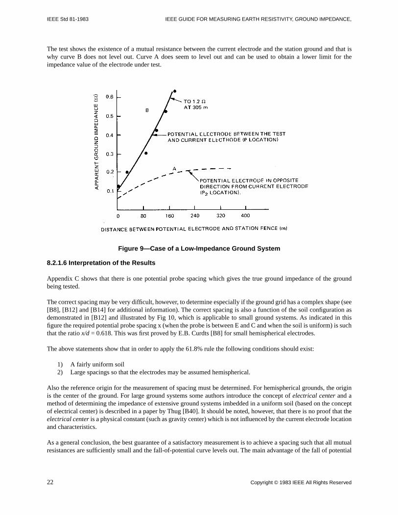
A representative curve for a large grid ground is shown in Fig 9. The data for this figure were taken from a test madeon a station that had a ground grid approximately 125 m by 150 m. Distances were measured from the station fence;hence the impedance is not zero at zero distance on the curve. Curve B is obtained with the potential probe locatedbetween E and C. Curve A is obtained with the potential probe located at the opposite side with respect to the currentelectrode C.
Copyright © 1983 IEEE All Rights Reserved 21
IEEE Std 81-1983 IEEE GUIDE FOR MEASURING EARTH RESISTIVITY, GROUND IMPEDANCE,
The test shows the existence of a mutual resistance between the current electrode and the station ground and that iswhy curve B does not level out. Curve A does seem to level out and can be used to obtain a lower limit for theimpedance value of the electrode under test.
Figure 9—Case of a Low-Impedance Ground System
8.2.1.6 Interpretation of the Results
Appendix C shows that there is one potential probe spacing which gives the true ground impedance of the groundbeing tested.
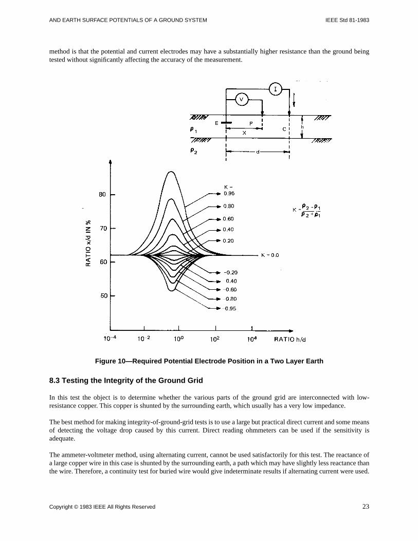
The correct spacing may be very difficult, however, to determine especially if the ground grid has a complex shape (see[B8], [B12] and [B14] for additional information). The correct spacing is also a function of the soil configuration asdemonstrated in [B12] and illustrated by Fig 10, which is applicable to small ground systems. As indicated in thisfigure the required potential probe spacing x (when the probe is between E and C and when the soil is uniform) is suchthat the ratio x/d = 0.618. This was first proved by E.B. Curdts [B8] for small hemispherical electrodes.
The above statements show that in order to apply the 61.8% rule the following conditions should exist:
1) A fairly uniform soil2) Large spacings so that the electrodes may be assumed hemispherical.
Also the reference origin for the measurement of spacing must be determined. For hemispherical grounds, the originis the center of the ground. For large ground systems some authors introduce the concept of electrical center and amethod of determining the impedance of extensive ground systems imbedded in a uniform soil (based on the conceptof electrical center) is described in a paper by Thug [B40]. It should be noted, however, that there is no proof that theelectrical center is a physical constant (such as gravity center) which is not influenced by the current electrode locationand characteristics.
As a general conclusion, the best guarantee of a satisfactory measurement is to achieve a spacing such that all mutualresistances are sufficiently small and the fall-of-potential curve levels out. The main advantage of the fall of potential
22 Copyright © 1983 IEEE All Rights Reserved
AND EARTH SURFACE POTENTIALS OF A GROUND SYSTEM IEEE Std 81-1983
method is that the potential and current electrodes may have a substantially higher resistance than the ground beingtested without significantly affecting the accuracy of the measurement.
Figure 10—Required Potential Electrode Position in a Two Layer Earth
8.3 Testing the Integrity of the Ground Grid
In this test the object is to determine whether the various parts of the ground grid are interconnected with low-resistance copper. This copper is shunted by the surrounding earth, which usually has a very low impedance.
The best method for making integrity-of-ground-grid tests is to use a large but practical direct current and some meansof detecting the voltage drop caused by this current. Direct reading ohmmeters can be used if the sensitivity isadequate.
The ammeter-voltmeter method, using alternating current, cannot be used satisfactorily for this test. The reactance ofa large copper wire in this case is shunted by the surrounding earth, a path which may have slightly less reactance thanthe wire. Therefore, a continuity test for buried wire would give indeterminate results if alternating current were used.
Copyright © 1983 IEEE All Rights Reserved 23
IEEE Std 81-1983 IEEE GUIDE FOR MEASURING EARTH RESISTIVITY, GROUND IMPEDANCE,
By extension of this reasoning, one concludes that it is practically impossible to sensibly lower the impedance betweentwo ground grids which are any distance apart, each of which has an impedance in the order of 0.1 Ω at 60 Hz. Theaddition of copper connectors, however large, will not lower the reactance between the two ground grids. The resistivecomponent can be lowered by additional connectors, and this component is used to determine the integrity of theground grid.
One practical integrity test consists of passing about five amperes into the ground grid between two points to bechecked. The voltage drop across these points is measured with a millivoltmeter or portable potentiometer and theeffective resistance is calculated from the current and voltage readings. From these readings and the calculatedresistance of copper it can be determined whether there is an adequate connection. For those ground systems that havea direct voltage between points, the change of voltage caused by the test current is used to calculate the resistance.
For the majority of large ground systems in service there will be a realtively large alternating voltage between thepoints to be measured compared with the direct millivolts to be detected. The effects of the alternating component onthe detector can be mitigated by shunting the moving coil in the millivoltmeter, or the galvanometer in thepotentiometer, with a capacitor of 20 µF or more. This capacitor should preferably have a liquid impregnated paperdielectric, but some modern electrolytic condensers have so little leakage that they can be used in this application.
8.4 Instrumentation
The instruments used for ground resistance measurements are identical to those used for resistivity measurements.These instruments are described in Section 12.
9. Earth Potential
9.1 Equipotential Lines
As a result of current from an electrode to earth and through its earth path, equipotential surfaces plotted at right anglesto these current lines will assume a shape controlled by the path of the current. The density of equipotential surfaces,having equal voltage differences between them, across a path in a given direction determines the step voltage whichmay be encountered. This gradient will be highest near the grounding electrode.
The distance between equipotential surfaces, measured along the surface of the earth radially from the groundingconnection, will vary with a number of factors. These include variations in resistivity of the earth, the presence ofburied pipes, conduit, railroad rails, steel fences, metallic cable sheaths, and the presence of overhead lines carryingground current.
As indicated in 8.1, some of the ground-fault current tends to return to the source under the transmission line whichcarries the current. Consequently it will be found that the ground potential under the transmission line carrying faultcurrent will have a steeper gradient than in the adjoining earth. This results in changing the pattern of the equipotentiallines whenever a different transmission line terminating at the station is faulted. Therefore, equipotential lines cannotbe established simply by measuring resistance from the grounding connection to various points around it.
When once established, the voltage between the equipotential lines for a given fault condition can be expected to varydirectly with ground-fault current magnitude. This assumes no change in the resistivity of the earth around thegrounding system during the flow of fault current.
9.2 Potential Contour Surveys
A potential contour survey is made to locate possible hazardous potential gradients in the vicinity of groundedelectrical structures during fault conditions [B7], [B29]. The voltage drop to points surrounding the structure is
24 Copyright © 1983 IEEE All Rights Reserved
AND EARTH SURFACE POTENTIALS OF A GROUND SYSTEM IEEE Std 81-1983
measured from a known reference point and plotted on a map of the location. A potential contour map may then bedrawn by connecting points of equal potential with continuous lines. If the contour lines have equal voltage differencesbetween them, the closer the lines, the greater the hazard. Actual gradients due to ground-fault current are obtained bymultiplying test current gradients by the ratio of the fault current to test current.
The most accurate measurements of potential gradients are made with the voltmeter-ammeter method. A knowncurrent, between 50 A and 100 A, held constant during test, is passed through the ground grid to a remote ground testelectrode and returned through an insulated conductor. A remotely located ground test electrode is necessary to preventgradient distortion, caused by the mutual impedance of inadequately spaced ground electrodes. This distance may varyfrom 300 m, for a small ground grid to a mile or more for larger installations. Measurements should be made with avery-high-impedance voltmeter on the surface of the earth along profile lines radial to the point of connection to theground grid. Unless suitable means are employed to mask out residual ground current, the test current must be ofsufficient magnitude to do so. At the same time care must be taken to prevent heating and drying of the soil in contactwith the ground grid or test electrode to avoid variations in voltage gradients in a series of measurements. Economicsand the necessary detail required will determine the number of measurements to be made.
When more than one overhead line or underground cable are connected to a substation, potential gradients in andaround the substation may be quite different for faults on different lines or cables. Likewise, faults at differentlocations in large substations may result in differences in potential gradients in and around the substation. It may,therefore, be advantageous to determine potential gradients in and around a large substation for two or more faultconditions.
Underground metallic structures, for example, neutral conductors, metallic cable sheaths, metallic water and gas lines,etc, metallic structures on the surface of the ground such as railroad rails and fences, and overhead ground wires in thevicinity of a substation, whether connected to the ground grid or not, will usually have a significant effect on potentialgradients and should be considered when making potential gradient measurements.
When a potential gradient survey cannot be justified economically, potential gradients may be calculated from groundresistance or soil resistivity measurements. The accuracy of such calculations will be dependent upon the accuracy ofthe measurements, and the unknown abnormalities of the earth around and below the ground grid.
The adequacy of such calculations may be verified with relatively few potential gradient measurements.
9.3 Step and Touch Voltages
The magnitude of step and touch voltage (see Fig 11) may be scaled off of a potential contour map of the site oractually measured by the voltmeter-ammeter method. These values are proportional to the earth current and (providedthat the deep soil resistivity is constant) to the top soil resistivity.
NOTE — A variation of resistivity of the top soil in some cases increases the ground resistance. This in turn may cause a variationin the earth current. The changes in step and touch voltages should therefore be determined by taking into accountsimultaneously, top-soil resistivity and earth current variations.
Copyright © 1983 IEEE All Rights Reserved 25
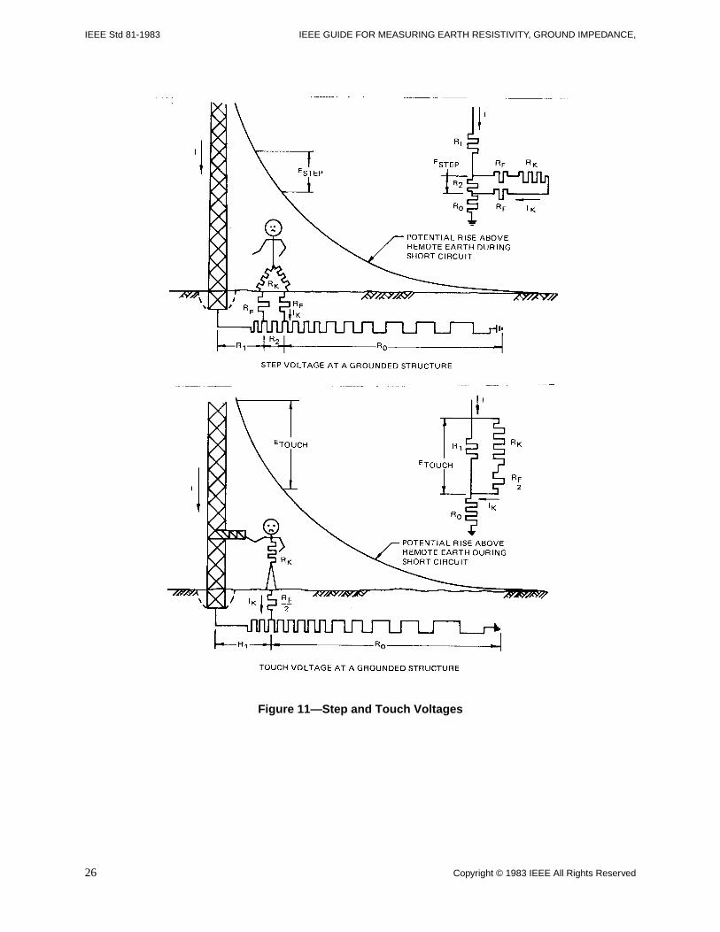
IEEE Std 81-1983 IEEE GUIDE FOR MEASURING EARTH RESISTIVITY, GROUND IMPEDANCE,
Figure 11—Step and Touch Voltages
26 Copyright © 1983 IEEE All Rights Reserved
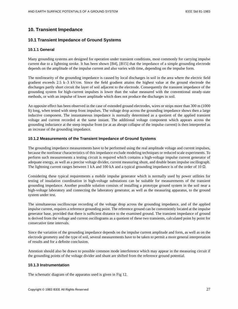
AND EARTH SURFACE POTENTIALS OF A GROUND SYSTEM IEEE Std 81-1983
10. Transient Impedance
10.1 Transient Impedance of Ground Systems
10.1.1 General
Many grounding systems are designed for operation under transient conditions, most commonly for carrying impulsecurrent due to a lightning stroke. It has been shown [B4], [B15] that the impedance of a simple grounding electrodedepends on the amplitude of the impulse current and also varies with time, depending on the impulse form.
The nonlinearity of the grounding impedance is caused by local discharges in soil in the area where the electric fieldgradient exceeds 2.5 k–3 kV/cm. Since the field gradient attains the highest value at the ground electrode thedischarges partly short circuit the layer of soil adjacent to the electrode. Consequently the transient impedance of thegrounding system for high-current impulses is lower than the value measured with the conventional steady-statemethods, or with an impulse of lower amplitude which does not produce the discharges in soil.
An opposite effect has been observed in the case of extended ground electrodes, wires or strips more than 300 m (1000ft) long, when tested with steep front impulses. The voltage drop across the grounding impedance shows then a largeinductive component. The instantaneous impedance is normally determined as a quotient of the applied transientvoltage and current recorded at the same instant. The additional voltage component which appears across thegrounding inductance at the steep impulse front (or at an abrupt collapse of the impulse current) is then interpreted asan increase of the grounding impedance.
10.1.2 Measurements of the Transient Impedance of Ground Systems
The grounding impedance measurements have to be performed using the real amplitude voltage and current impulses,because the nonlinear characteristics of this impedance exclude modeling techniques or reduced scale experiments. Toperform such measurements a testing circuit is required which contains a high-voltage impulse current generator ofadequate energy, as well as a precise voltage divider, current measuring shunt, and double beam impulse oscillograph.The lightning current ranges between 1 kA and 100 kA and a typical grounding impedance is of the order of 10 Ω.
Considering these typical requirements a mobile impulse generator which is normally used by power utilities fortesting of insulation coordination in high-voltage substations can be suitable for measurements of the transientgrounding impedance. Another possible solution consists of installing a prototype ground system in the soil near ahigh-voltage laboratory and connecting the laboratory generator, as well as the measuring apparatus, to the groundsystem under test.
The simultaneous oscilloscope recording of the voltage drop across the grounding impedance, and of the appliedimpulse current, requires a reference grounding point. The reference ground can be conveniently located at the impulsegenerator base, provided that there is sufficient distance to the examined ground. The transient impedance of groundis derived from the voltage and current oscillograms as a quotient of these two transients, calculated point by point forconsecutive time intervals.
Since the variation of the grounding impedance depends on the impulse current amplitude and form, as well as on theelectrode geometry and the type of soil, several measurements have to be taken to permit a more general interpretationof results and for a definite conclusion.
Attention should also be drawn to possible common mode interference which may appear in the measuring circuit ifthe grounding points of the voltage divider and shunt are shifted from the reference ground potential.
10.1.3 Instrumentation
The schematic diagram of the apparatus used is given in Fig 12.
Copyright © 1983 IEEE All Rights Reserved 27
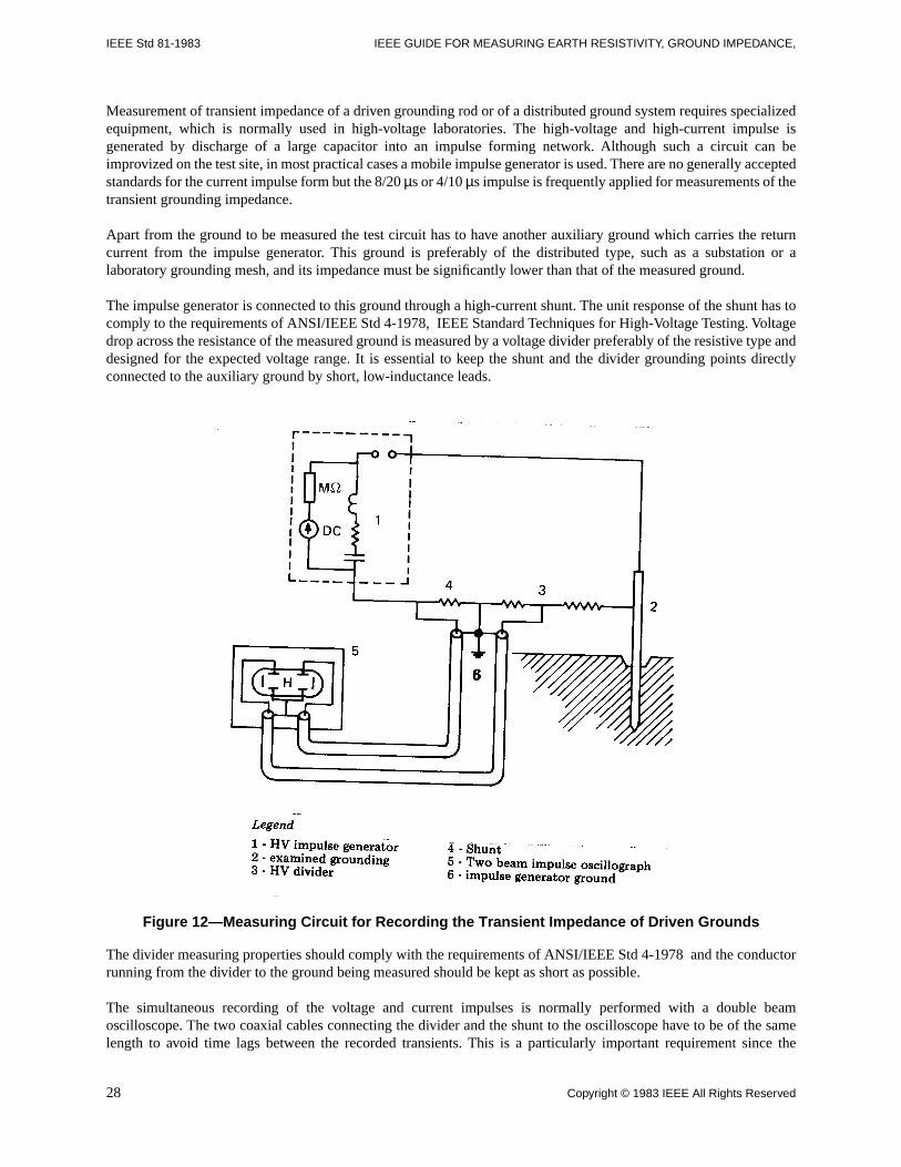
IEEE Std 81-1983 IEEE GUIDE FOR MEASURING EARTH RESISTIVITY, GROUND IMPEDANCE,
Measurement of transient impedance of a driven grounding rod or of a distributed ground system requires specializedequipment, which is normally used in high-voltage laboratories. The high-voltage and high-current impulse isgenerated by discharge of a large capacitor into an impulse forming network. Although such a circuit can beimprovized on the test site, in most practical cases a mobile impulse generator is used. There are no generally acceptedstandards for the current impulse form but the 8/20 µs or 4/10 µs impulse is frequently applied for measurements of thetransient grounding impedance.
Apart from the ground to be measured the test circuit has to have another auxiliary ground which carries the returncurrent from the impulse generator. This ground is preferably of the distributed type, such as a substation or alaboratory grounding mesh, and its impedance must be significantly lower than that of the measured ground.
The impulse generator is connected to this ground through a high-current shunt. The unit response of the shunt has tocomply to the requirements of ANSI/IEEE Std 4-1978, IEEE Standard Techniques for High-Voltage Testing. Voltagedrop across the resistance of the measured ground is measured by a voltage divider preferably of the resistive type anddesigned for the expected voltage range. It is essential to keep the shunt and the divider grounding points directlyconnected to the auxiliary ground by short, low-inductance leads.
Figure 12—Measuring Circuit for Recording the Transient Impedance of Driven Grounds
The divider measuring properties should comply with the requirements of ANSI/IEEE Std 4-1978 and the conductorrunning from the divider to the ground being measured should be kept as short as possible.
The simultaneous recording of the voltage and current impulses is normally performed with a double beamoscilloscope. The two coaxial cables connecting the divider and the shunt to the oscilloscope have to be of the samelength to avoid time lags between the recorded transients. This is a particularly important requirement since the
28 Copyright © 1983 IEEE All Rights Reserved
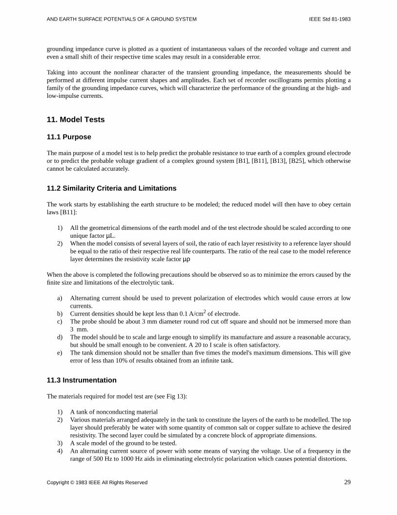
AND EARTH SURFACE POTENTIALS OF A GROUND SYSTEM IEEE Std 81-1983
grounding impedance curve is plotted as a quotient of instantaneous values of the recorded voltage and current andeven a small shift of their respective time scales may result in a considerable error.
Taking into account the nonlinear character of the transient grounding impedance, the measurements should beperformed at different impulse current shapes and amplitudes. Each set of recorder oscillograms permits plotting afamily of the grounding impedance curves, which will characterize the performance of the grounding at the high- andlow-impulse currents.
11. Model Tests
11.1 Purpose
The main purpose of a model test is to help predict the probable resistance to true earth of a complex ground electrodeor to predict the probable voltage gradient of a complex ground system [B1], [B11], [B13], [B25], which otherwisecannot be calculated accurately.
11.2 Similarity Criteria and Limitations
The work starts by establishing the earth structure to be modeled; the reduced model will then have to obey certainlaws [B11]:
1) All the geometrical dimensions of the earth model and of the test electrode should be scaled according to oneunique factor µL.
2) When the model consists of several layers of soil, the ratio of each layer resistivity to a reference layer shouldbe equal to the ratio of their respective real life counterparts. The ratio of the real case to the model referencelayer determines the resistivity scale factor µρ
When the above is completed the following precautions should be observed so as to minimize the errors caused by thefinite size and limitations of the electrolytic tank.
a) Alternating current should be used to prevent polarization of electrodes which would cause errors at lowcurrents.
b) Current densities should be kept less than 0.1 A/cm2 of electrode.c) The probe should be about 3 mm diameter round rod cut off square and should not be immersed more than
3 mm.d) The model should be to scale and large enough to simplify its manufacture and assure a reasonable accuracy,
but should be small enough to be convenient. A 20 to I scale is often satisfactory.e) The tank dimension should not be smaller than five times the model's maximum dimensions. This will give
error of less than 10% of results obtained from an infinite tank.
11.3 Instrumentation
The materials required for model test are (see Fig 13):
1) A tank of nonconducting material2) Various materials arranged adequately in the tank to constitute the layers of the earth to be modelled. The top
layer should preferably be water with some quantity of common salt or copper sulfate to achieve the desiredresistivity. The second layer could be simulated by a concrete block of appropriate dimensions.
3) A scale model of the ground to be tested.4) An alternating current source of power with some means of varying the voltage. Use of a frequency in the
range of 500 Hz to 1000 Hz aids in eliminating electrolytic polarization which causes potential distortions.
Copyright © 1983 IEEE All Rights Reserved 29
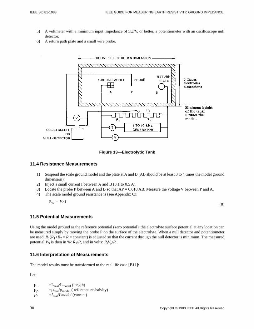
IEEE Std 81-1983 IEEE GUIDE FOR MEASURING EARTH RESISTIVITY, GROUND IMPEDANCE,
5) A voltmeter with a minimum input impedance of 5Ω/V, or better, a potentiometer with an oscilloscope nulldetector.
6) A return path plate and a small wire probe.
Figure 13—Electrolytic Tank
11.4 Resistance Measurements
1) Suspend the scale ground model and the plate at A and B (AB should be at least 3 to 4 times the model grounddimension).
2) Inject a small current I between A and B (0.1 to 0.5 A).3) Locate the probe P between A and B so that AP = 0.618 AB. Measure the voltage V between P and A.4) The scale model ground resistance is (see Appendix C):
(8)
11.5 Potential Measurements
Using the model ground as the reference potential (zero potential), the electrolyte surface potential at any location canbe measured simply by moving the probe P on the surface of the electrolyte. When a null detector and potentiometerare used, R1(R1+R2 = R = constant) is adjusted so that the current through the null detector is minimum. The measuredpotential VS is then in %: R1/R, and in volts: RlVp/R .
11.6 Interpretation of Measurements
The model results must be transformed to the real life case [B11]:
Let:
µL =Lreal/Lmodel (length)µρ =ρreal/ρmodel ( reference resistivity)µI =Ireal/I model (current)
RA V I⁄=
30 Copyright © 1983 IEEE All Rights Reserved
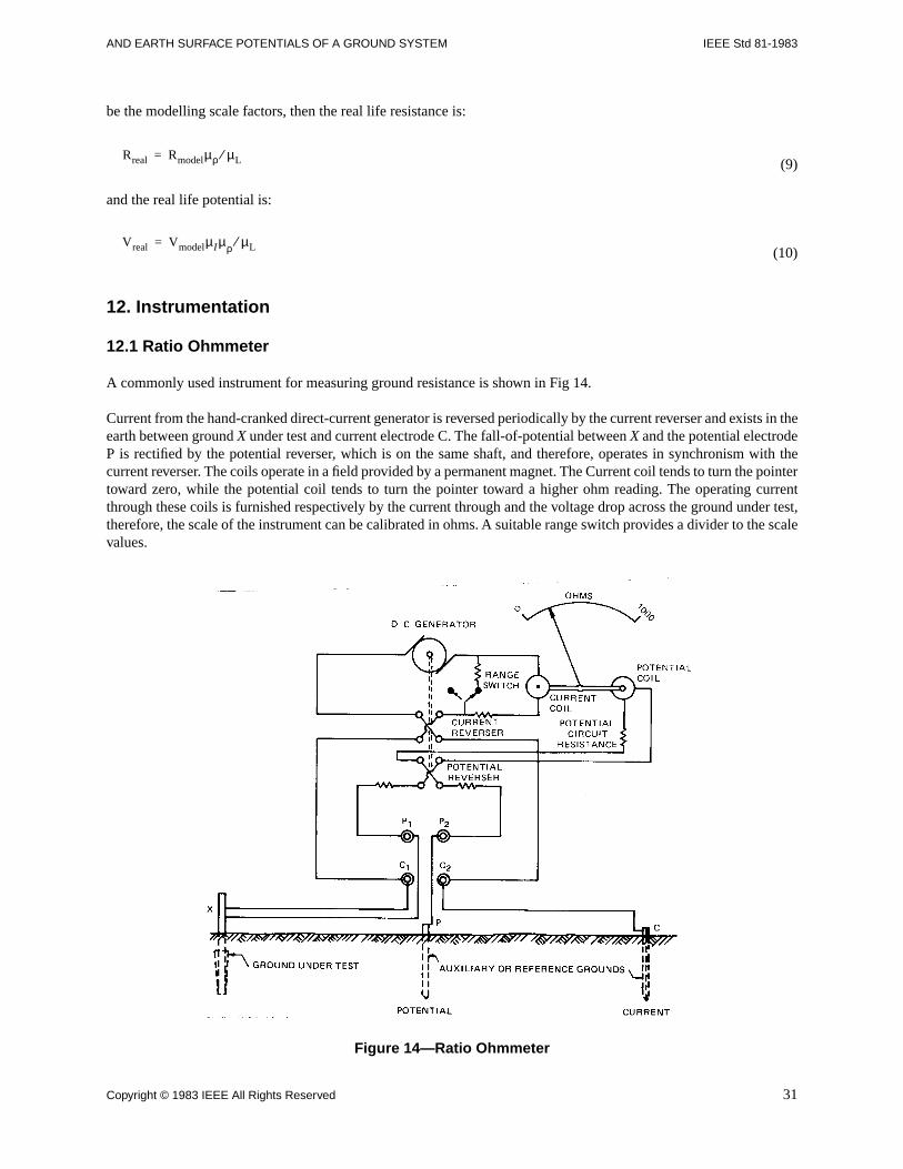
AND EARTH SURFACE POTENTIALS OF A GROUND SYSTEM IEEE Std 81-1983
be the modelling scale factors, then the real life resistance is:
(9)
and the real life potential is:
(10)
12. Instrumentation
12.1 Ratio Ohmmeter
A commonly used instrument for measuring ground resistance is shown in Fig 14.
Current from the hand-cranked direct-current generator is reversed periodically by the current reverser and exists in theearth between ground X under test and current electrode C. The fall-of-potential between X and the potential electrodeP is rectified by the potential reverser, which is on the same shaft, and therefore, operates in synchronism with thecurrent reverser. The coils operate in a field provided by a permanent magnet. The Current coil tends to turn the pointertoward zero, while the potential coil tends to turn the pointer toward a higher ohm reading. The operating currentthrough these coils is furnished respectively by the current through and the voltage drop across the ground under test,therefore, the scale of the instrument can be calibrated in ohms. A suitable range switch provides a divider to the scalevalues.
Figure 14—Ratio Ohmmeter
Rreal Rmodelµρ µL⁄=
Vreal VmodelµIµρ µL⁄=
Copyright © 1983 IEEE All Rights Reserved 31
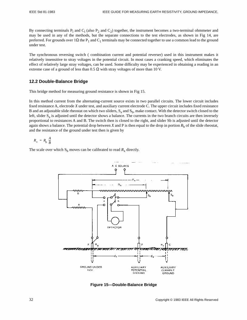
IEEE Std 81-1983 IEEE GUIDE FOR MEASURING EARTH RESISTIVITY, GROUND IMPEDANCE,
By connecting terminals Pl and Cl (also P2 and C2) together, the instrument becomes a two-terminal ohmmeter andmay be used in any of the methods, but the separate connections to the test electrodes, as shown in Fig 14, arepreferred. For grounds over 1Ω the P1 and C1 terminals may be connected together to use a common lead to the groundunder test.
The synchronous reversing switch ( combination current and potential reverser) used in this instrument makes itrelatively insensitive to stray voltages in the potential circuit. In most cases a cranking speed, which eliminates theeffect of relatively large stray voltages, can be used. Some difficulty may be experienced in obtaining a reading in anextreme case of a ground of less than 0.5 Ω with stray voltages of more than 10 V.
12.2 Double-Balance Bridge
This bridge method for measuring ground resistance is shown in Fig 15.
In this method current from the alternating-current source exists in two parallel circuits. The lower circuit includesfixed resistance A, electrode X under test, and auxiliary current electrode C. The upper circuit includes fixed resistanceB and an adjustable slide rheostat on which two sliders, Sa and Sb, make contact. With the detector switch closed to theleft, slider Sa is adjusted until the detector shows a balance. The currents in the two branch circuits are then inverselyproportional to resistances A and B. The switch then is closed to the right, and slider Sb is adjusted until the detectoragain shows a balance. The potential drop between X and P is then equal to the drop in portion Rb of the slide rheostat,and the resistance of the ground under test then is given by
The scale over which Sb moves can be calibrated to read Rx directly.
Figure 15—Double-Balance Bridge
Rx R=b
AB---
32 Copyright © 1983 IEEE All Rights Reserved
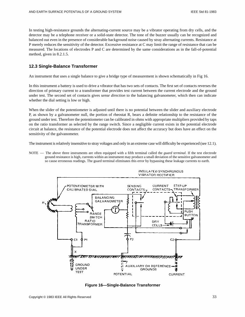
AND EARTH SURFACE POTENTIALS OF A GROUND SYSTEM IEEE Std 81-1983
In testing high-resistance grounds the alternating-current source may be a vibrator operating from dry cells, and thedetector may be a telephone receiver or a solid-state detector. The tone of the buzzer usually can be recognized andbalanced out even in the presence of considerable background noise caused by stray alternating currents. Resistance atP merely reduces the sensitivity of the detector. Excessive resistance at C may limit the range of resistance that can bemeasured. The locations of electrodes P and C are determined by the same considerations as in the fall-of-potentialmethod, given in 8.2.1.5.
12.3 Single-Balance Transformer
An instrument that uses a single balance to give a bridge type of measurement is shown schematically in Fig 16.
In this instrument a battery is used to drive a vibrator that has two sets of contacts. The first set of contacts reverses thedirection of primary current to a transformer that provides test current between the current electrode and the groundunder test. The second set of contacts gives sense direction to the balancing galvanometer, which then can indicatewhether the dial setting is low or high.
When the slider of the potentiometer is adjusted until there is no potential between the slider and auxiliary electrodeP, as shown by a galvanometer null, the portion of rheostat R, bears a definite relationship to the resistance of theground under test. Therefore the potentiometer can be calibrated in ohms with appropriate multipliers provided by tapson the ratio transformer as selected by the range switch. Since a negligible current exists in the potential electrodecircuit at balance, the resistance of the potential electrode does not affect the accuracy but does have an effect on thesensitivity of the galvanometer.
The instrument is relatively insensitive to stray voltages and only in an extreme case will difficulty be experienced (see 12.1).
NOTE — The above three instruments are often equipped with a fifth terminal called the guard terminal. If the test electrodeground resistance is high, currents within an instrument may produce a small deviation of the sensitive galvanometer andso cause erroneous readings. The guard terminal eliminates this error by bypassing these leakage currents to earth.
Figure 16—Single-Balance Transformer
Copyright © 1983 IEEE All Rights Reserved 33
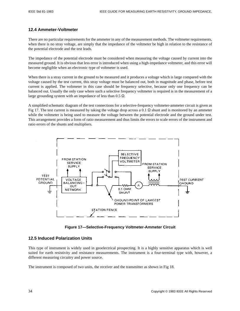
IEEE Std 81-1983 IEEE GUIDE FOR MEASURING EARTH RESISTIVITY, GROUND IMPEDANCE,
12.4 Ammeter-Voltmeter
There are no particular requirements for the ammeter in any of the measurement methods. The voltmeter requirements,when there is no stray voltage, are simply that the impedance of the voltmeter be high in relation to the resistance ofthe potential electrode and the test leads.
The impedance of the potential electrode must be considered when measuring the voltage caused by current into themeasured ground. It is obvious that less error is introduced when using a high-impedance voltmeter, and this error willbecome negligible when an electronic type of voltmeter is used.
When there is a stray current in the ground to be measured and it produces a voltage which is large compared with thevoltage caused by the test current, this stray voltage must be balanced out, both in magnitude and phase, before testcurrent is applied. The voltmeter in this case should be frequency selective, because only one frequency can bebalanced out. Usually the only case where such a selective frequency voltmeter is required is in the measurement of alarge grounding system with an impedance of less than 0.5 Ω.
A simplified schematic diagram of the test connections for a selective-frequency voltmeter-ammeter circuit is given asFig 17. The test current is measured by taking the voltage drop across a 0.1 Ω shunt and is monitored by an ammeterwhile the voltmeter is being used to measure the voltage between the potential electrode and the ground under test.This arrangement provides a form of ratio measurement and thus limits the errors to scale errors of the instrument andratio errors of the shunts and multipliers.
Figure 17—Selective-Frequency Voltmeter-Ammeter Circuit
12.5 Induced Polarization Units
This type of instrument is widely used in geoelectrical prospecting. It is a highly sensitive apparatus which is wellsuited for earth resistivity and resistance measurements. The instrument is a four-terminal type with, however, adifferent measuring circuitry and power source.
The instrument is composed of two units, the receiver and the transmitter as shown in Fig 18.
34 Copyright © 1983 IEEE All Rights Reserved
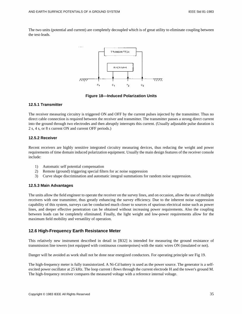
AND EARTH SURFACE POTENTIALS OF A GROUND SYSTEM IEEE Std 81-1983
The two units (potential and current) are completely decoupled which is of great utility to eliminate coupling betweenthe test-leads.
Figure 18—Induced Polarization Units
12.5.1 Transmitter
The receiver measuring circuitry is triggered ON and OFF by the current pulses injected by the transmitter. Thus nodirect cable connection is required between the receiver and transmitter. The transmitter passes a strong direct currentinto the ground through two electrodes and then abruptly interrupts this current. (Usually adjustable pulse duration is2 s, 4 s, or 8 s current ON and current OFF periods.)
12.5.2 Receiver
Recent receivers are highly sensitive integrated circuitry measuring devices, thus reducing the weight and powerrequirements of time domain induced polarization equipment. Usually the main design features of the receiver consoleinclude:
1) Automatic self potential compensation2) Remote (ground) triggering special filters for ac noise suppression3) Curve shape discrimination and automatic integral summations for random noise suppression.
12.5.3 Main Advantages
The units allow the field engineer to operate the receiver on the survey lines, and on occasion, allow the use of multiplereceivers with one transmitter, thus greatly enhancing the survey efficiency. Due to the inherent noise suppressioncapability of this system, surveys can be conducted much closer to sources of spurious electrical noise such as powerlines, and deeper effective penetration can be obtained without increasing power requirements. Also the couplingbetween leads can be completely eliminated. Finally, the light weight and low-power requirements allow for themaximum field mobility and versatility of operation.
12.6 High-Frequency Earth Resistance Meter
This relatively new instrument described in detail in [B32] is intended for measuring the ground resistance oftransmission line towers (not equipped with continuous counterpoises) with the static wires ON (insulated or not).
Danger will be avoided as work shall not be done near energized conductors. For operating principle see Fig 19.
The high-frequency meter is fully transistorized. A Ni-Cd battery is used as the power source. The generator is a self-excited power oscillator at 25 kHz. The loop current i flows through the current electrode H and the tower's ground M.The high-frequency receiver compares the measured voltage with a reference internal voltage.
Copyright © 1983 IEEE All Rights Reserved 35
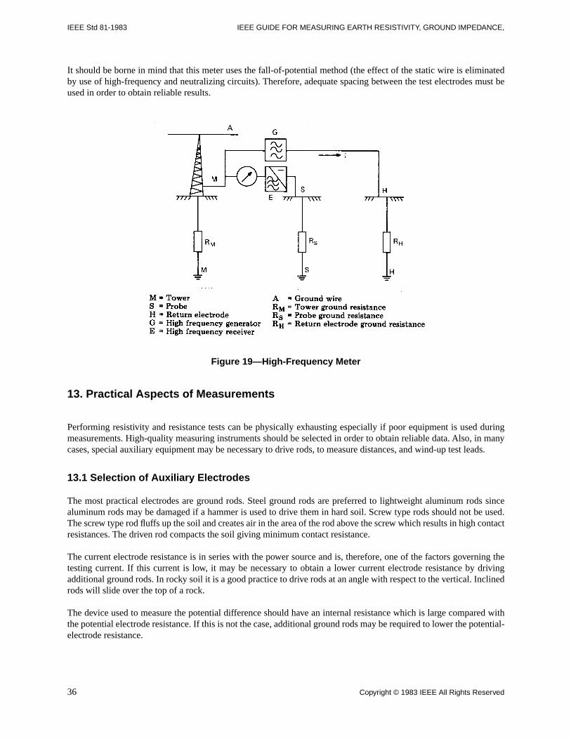
IEEE Std 81-1983 IEEE GUIDE FOR MEASURING EARTH RESISTIVITY, GROUND IMPEDANCE,
It should be borne in mind that this meter uses the fall-of-potential method (the effect of the static wire is eliminatedby use of high-frequency and neutralizing circuits). Therefore, adequate spacing between the test electrodes must beused in order to obtain reliable results.
Figure 19—High-Frequency Meter
13. Practical Aspects of Measurements
Performing resistivity and resistance tests can be physically exhausting especially if poor equipment is used duringmeasurements. High-quality measuring instruments should be selected in order to obtain reliable data. Also, in manycases, special auxiliary equipment may be necessary to drive rods, to measure distances, and wind-up test leads.
13.1 Selection of Auxiliary Electrodes
The most practical electrodes are ground rods. Steel ground rods are preferred to lightweight aluminum rods sincealuminum rods may be damaged if a hammer is used to drive them in hard soil. Screw type rods should not be used.The screw type rod fluffs up the soil and creates air in the area of the rod above the screw which results in high contactresistances. The driven rod compacts the soil giving minimum contact resistance.
The current electrode resistance is in series with the power source and is, therefore, one of the factors governing thetesting current. If this current is low, it may be necessary to obtain a lower current electrode resistance by drivingadditional ground rods. In rocky soil it is a good practice to drive rods at an angle with respect to the vertical. Inclinedrods will slide over the top of a rock.
The device used to measure the potential difference should have an internal resistance which is large compared withthe potential electrode resistance. If this is not the case, additional ground rods may be required to lower the potential-electrode resistance.
36 Copyright © 1983 IEEE All Rights Reserved
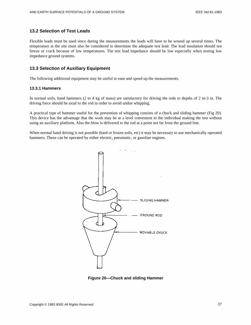
AND EARTH SURFACE POTENTIALS OF A GROUND SYSTEM IEEE Std 81-1983
13.2 Selection of Test Leads
Flexible leads must be used since during the measurements the leads will have to be wound up several times. Thetemperature at the site must also be considered to determine the adequate test lead. The lead insulation should notfreeze or crack because of low temperatures. The test lead impedance should be low especially when testing lowimpedance ground systems.
13.3 Selection of Auxiliary Equipment
The following additional equipment may be useful to ease and speed up the measurements.
13.3.1 Hammers
In normal soils, hand hammers (2 to 4 kg of mass) are satisfactory for driving the rods to depths of 2 m-3 m. Thedriving force should be axial to the rod in order to avoid undue whipping.
A practical type of hammer useful for the prevention of whipping consists of a chuck and sliding hammer (Fig 20).This device has the advantage that the work may be at a level convenient to the individual making the test withoutusing an auxiliary platform. Also the blow is delivered to the rod at a point not far from the ground line.
When normal hand driving is not possible (hard or frozen soils, etc) it may be necessary to use mechanically operatedhammers. These can be operated by either electric, pneumatic, or gasoline engines.
Figure 20—Chuck and sliding Hammer
Copyright © 1983 IEEE All Rights Reserved 37
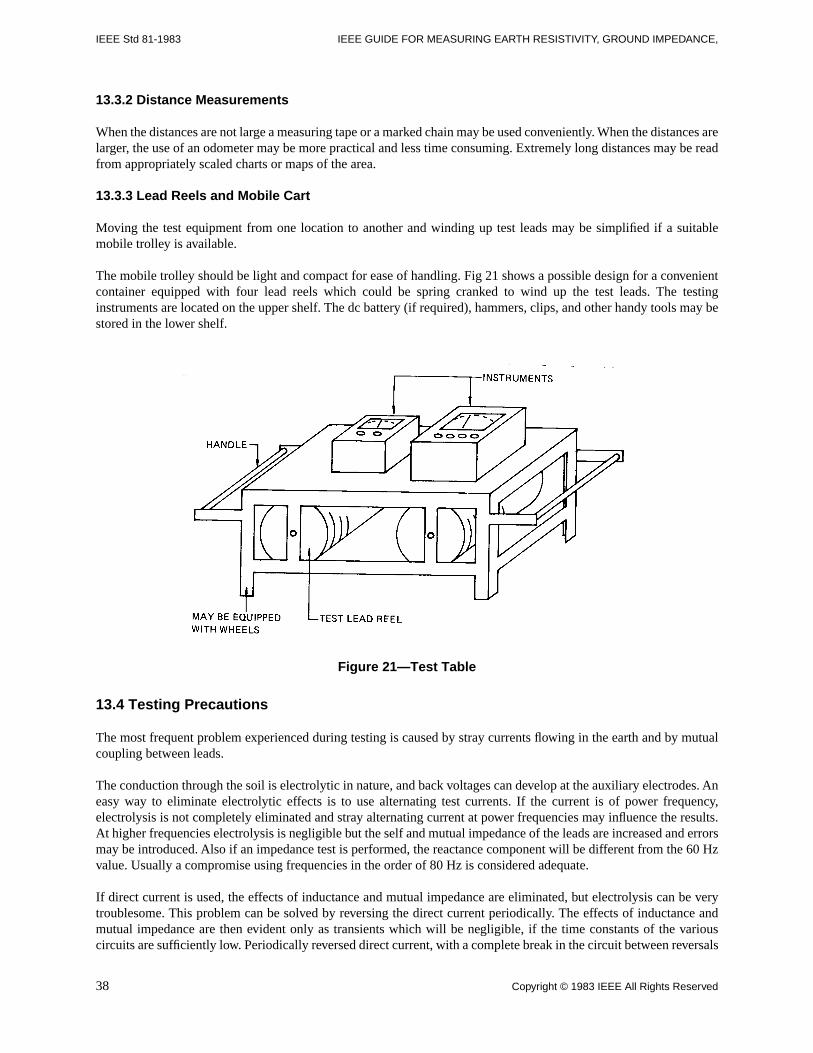
IEEE Std 81-1983 IEEE GUIDE FOR MEASURING EARTH RESISTIVITY, GROUND IMPEDANCE,
13.3.2 Distance Measurements
When the distances are not large a measuring tape or a marked chain may be used conveniently. When the distances arelarger, the use of an odometer may be more practical and less time consuming. Extremely long distances may be readfrom appropriately scaled charts or maps of the area.
13.3.3 Lead Reels and Mobile Cart
Moving the test equipment from one location to another and winding up test leads may be simplified if a suitablemobile trolley is available.
The mobile trolley should be light and compact for ease of handling. Fig 21 shows a possible design for a convenientcontainer equipped with four lead reels which could be spring cranked to wind up the test leads. The testinginstruments are located on the upper shelf. The dc battery (if required), hammers, clips, and other handy tools may bestored in the lower shelf.
Figure 21—Test Table
13.4 Testing Precautions
The most frequent problem experienced during testing is caused by stray currents flowing in the earth and by mutualcoupling between leads.
The conduction through the soil is electrolytic in nature, and back voltages can develop at the auxiliary electrodes. Aneasy way to eliminate electrolytic effects is to use alternating test currents. If the current is of power frequency,electrolysis is not completely eliminated and stray alternating current at power frequencies may influence the results.At higher frequencies electrolysis is negligible but the self and mutual impedance of the leads are increased and errorsmay be introduced. Also if an impedance test is performed, the reactance component will be different from the 60 Hzvalue. Usually a compromise using frequencies in the order of 80 Hz is considered adequate.
If direct current is used, the effects of inductance and mutual impedance are eliminated, but electrolysis can be verytroublesome. This problem can be solved by reversing the direct current periodically. The effects of inductance andmutual impedance are then evident only as transients which will be negligible, if the time constants of the variouscircuits are sufficiently low. Periodically reversed direct current, with a complete break in the circuit between reversals
38 Copyright © 1983 IEEE All Rights Reserved
AND EARTH SURFACE POTENTIALS OF A GROUND SYSTEM IEEE Std 81-1983
is the best power source for resistance or resistivity measurements. However, it is not adequate for impedancemeasurements.
13.5 Large Substations
The fall-of-potential method will give satisfactory results if the spacing between the grounding system under test andthe test electrodes is large enough. It may happen that for large substations, adequate spacings are difficult to achieveusing reels of wire. In these cases an outgoing line may be de-energized and used to inject test current into remoteearth. Telephone cables may also be used in some cases [B30], as potential lead only, provided the shielding factor isknown.
Copyright © 1983 IEEE All Rights Reserved 39
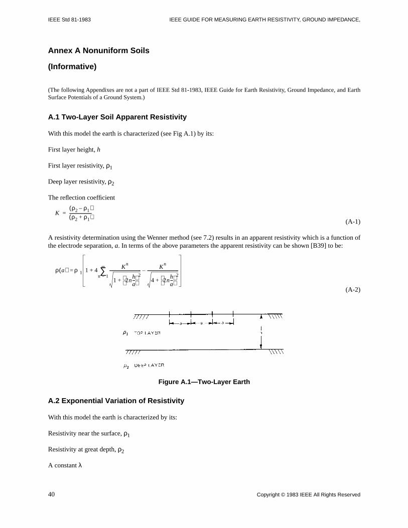
IEEE Std 81-1983 IEEE GUIDE FOR MEASURING EARTH RESISTIVITY, GROUND IMPEDANCE,
Annex A Nonuniform Soils
(Informative)
(The following Appendixes are not a part of IEEE Std 81-1983, IEEE Guide for Earth Resistivity, Ground Impedance, and EarthSurface Potentials of a Ground System.)
A.1 Two-Layer Soil Apparent Resistivity
With this model the earth is characterized (see Fig A.1) by its:
First layer height, h
First layer resistivity, ρ1
Deep layer resistivity, ρ2
The reflection coefficient
(A-1)
A resistivity determination using the Wenner method (see 7.2) results in an apparent resistivity which is a function ofthe electrode separation, a. In terms of the above parameters the apparent resistivity can be shown [B39] to be:
(A-2)
Figure A.1—Two-Layer Earth
A.2 Exponential Variation of Resistivity
With this model the earth is characterized by its:
Resistivity near the surface, ρ1
Resistivity at great depth, ρ2
A constant λ
Kρ2 ρ1–( )ρ2 ρ1+( )
----------------------=
ρ a( ) ρ1 1 4+ Kn
1 2nha---
2+
------------------------------- Kn
4 2nha---
2+
-------------------------------–n 1=
∞∑=
40 Copyright © 1983 IEEE All Rights Reserved
AND EARTH SURFACE POTENTIALS OF A GROUND SYSTEM IEEE Std 81-1983
A resistivity determination using the Wenner method (see 7.2) then results in an apparent resistivity which is a functionof the electrode separation, a. It is given [B42] by:
(A-3)
A.3 Ground Rod Resistance in a Two-Layer Soil
The ground resistance of a rod length l and radius r buried in the first layer of a two-layer soil is given by [B39]:
(A-4)
Where K is the reflection coefficient defined above.
NOTES:
1 — Since 0 ≤ K ≤ 1 and h Dcl174; l only the first few terms of the infinite series are significant.
2 — K = 0 corresponds to the uniform soil model with
If at a given site the ground resistance of a rod is measured for various lengths l1, l2, l3 … ln (at least three values), themeasured values R1, R2, R3, … Rn will provide a set of equations of type (A4) which can be solved to give the unknownvalues of ρ1, K and h.
It may happen in some cases that absurd, or (when more than three measurements axe made) contradictory results areobtained. This indicates either insufficient precision in the measurements or that the assumption of a uniform or two-layer soil was not an adequate approximation. It is preferable then, to use the four point or Wenner method with severalvalues of probe separation and to interpret the results by visual inspection of the apparent resistivity curve (see 7.2).
ρ a( ) ρ2 ρ2 ρ1–( )eλa–
2 eλa–
–( )–=
Rρ1
2πl-------- In
2lr
----- Kn 2nh l+
2nh l–-----------------ln
n 1=
∞∑+=
Rρ1
2πl-------- 2l
r-----ln=
Copyright © 1983 IEEE All Rights Reserved 41
IEEE Std 81-1983 IEEE GUIDE FOR MEASURING EARTH RESISTIVITY, GROUND IMPEDANCE,
42 Copyright © 1983 IEEE All Rights Reserved
Annex B Determination of an Earth Model
(Informative)
This Appendix is intended to assist the engineer in obtaining, from the measured resistivity data, the earth model whichbest fits the data. The earth model is limited to a two-layer soil configuration (see Fig A.1).
Let ρ0 be the apparent resistivity value as measured by the four-probe or Wenner method and ρ be the calculatedresistivity value assuming that earth is a two-layer configuration. Both ρ0 and p are functions of the probe spacing. Ap is given by (Eq A-2).
Let ψ (ρ1 ,K,h) be an error function given by:
(B-1)
where
N = total number of measured resistivity values with probe spacing, a, as the parameter.
In order to obtain the best fit ψ must be minimum. To determine the values of ρ, K, and h which minimize ψ the methodof steepest descent [B19] is used.
(B-2)
We have also:
(B-3)
In order to make sure that the calculations converge to the desired solution, the values of ∆ρ1, ∆ρ2, ∆h should be such that
(B-4)
τ, σ, γ being positive values and small enough to guarantee a solution with the desired accuracy. Normally valueswhich lead to the following solutions are satisfactory:
(B-5)
Using Eq B-3 and Eq B-4 the following equation is obtained
Ψ ρ1,K ,h( )ρ°m ρm–
ρ°m-----------------------
2
m 1=
N
∑=
∂ψ∂ρ1--------- 2
ρ° ρ–ρ°
--------------- ∂ρ∂ρ1---------
∂ψ∂ρ2--------- 2
ρ° ρ–ρ°
--------------- ∂ρ∂ρ2---------
1
N
∑–=
∂ψ∂h------- 2
ρ° ρ–ρ°
--------------- ∂ρ∂h------
1
N
∑–=
1
N
∑–=
∆ψ ∂ψ∂ρ1---------∆ρ1
∂ψ∂ρ2---------∆ρ2
∂ψ∂h-------∆h++=
∆ρ1 τ ∂ψ∂ρ1---------
∆ρ2 σ ∂ψ∂ρ2---------
∆h ϒ∂ψ∂h-------–=
–=
–=
∆ρ1 0.005 ρ1
∂ψ∂ρ1---------
∂ψ∂ρ1---------⁄
∆ρ2 0.005 ρ2
∂ψ∂ρ2---------
∂ψ∂ρ2---------⁄
∆h = 0.005 h ∂ψ∂h-------
∂ψ∂ρh---------⁄–
–=
–=
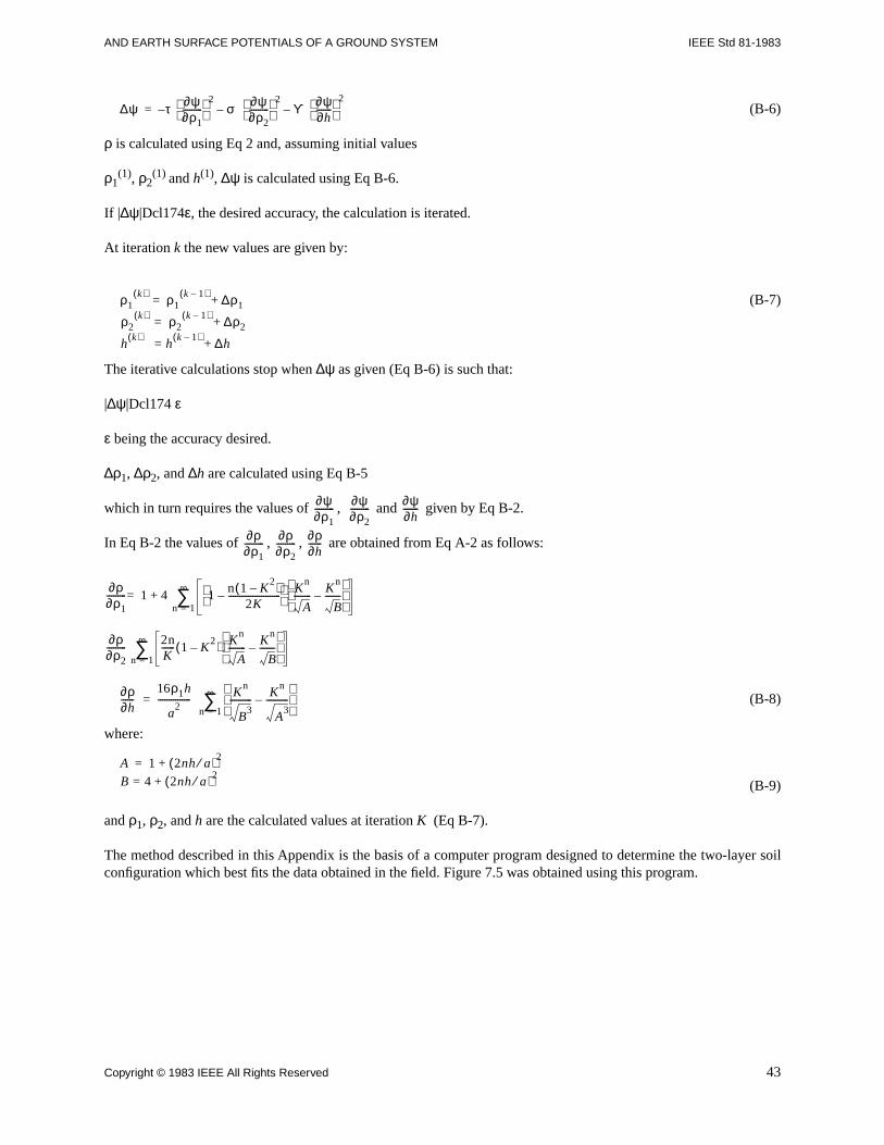
AND EARTH SURFACE POTENTIALS OF A GROUND SYSTEM IEEE Std 81-1983
(B-6)
ρ is calculated using Eq 2 and, assuming initial values
ρ1(1), ρ2
(1) and h(1), ∆ψ is calculated using Eq B-6.
If |∆ψ|Dcl174ε, the desired accuracy, the calculation is iterated.
At iteration k the new values are given by:
(B-7)
The iterative calculations stop when ∆ψ as given (Eq B-6) is such that:
|∆ψ|Dcl174 ε
ε being the accuracy desired.
∆ρ1, ∆ρ2, and ∆h are calculated using Eq B-5
which in turn requires the values of , and given by Eq B-2.
In Eq B-2 the values of , , are obtained from Eq A-2 as follows:
(B-8)
where:
(B-9)
and ρ1, ρ2, and h are the calculated values at iteration K (Eq B-7).
The method described in this Appendix is the basis of a computer program designed to determine the two-layer soilconfiguration which best fits the data obtained in the field. Figure 7.5 was obtained using this program.
∆ψ τ ∂ψ∂ρ1---------
2σ
∂ψ∂ρ2---------
2ϒ
∂ψ∂h-------
2–––=
ρ1k( ) ρ1
k 1–( ) ∆ρ1
ρ2k( )
= ρ2k 1–( ) ∆ρ2
hk( )
= hk 1–( ) ∆h+
+
+=
∂ψ∂ρ1--------- ∂ψ
∂ρ2--------- ∂ψ
∂h-------
∂ρ∂ρ1--------- ∂ρ
∂ρ2--------- ∂ρ
∂h------
∂ρ∂ρ1--------- 1 4 1 n 1 K
2–( )
2K------------------------–
Kn
A-------- K
n
B-------–
n 1=
∞∑+=
∂ρ∂ρ2---------
2nK------ 1 K
2–( ) K
n
A-------- K
n
B-------–
n 1=
∞∑
∂ρ∂h------
16ρ1h
a2
--------------- Kn
B3
---------- Kn
A3
----------–
n 1=
∞∑=
A 1 2nh a⁄( )2
B 4 2nh a⁄( )2+=
+=
Copyright © 1983 IEEE All Rights Reserved 43
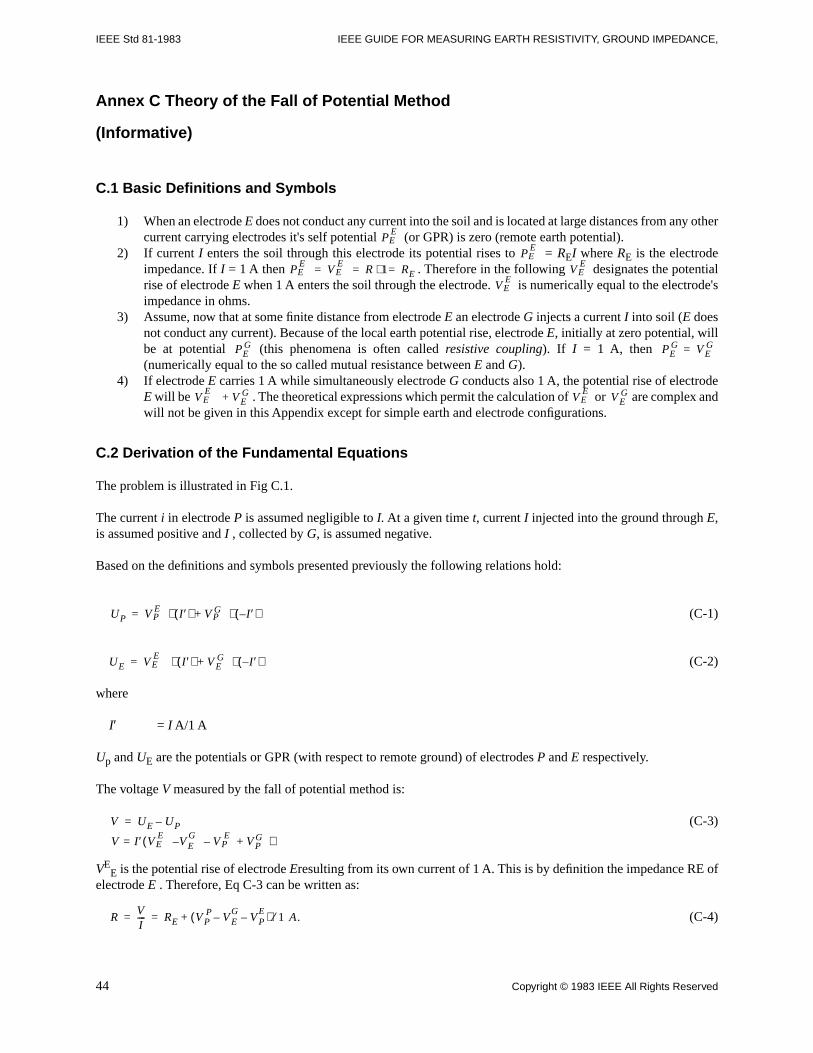
IEEE Std 81-1983 IEEE GUIDE FOR MEASURING EARTH RESISTIVITY, GROUND IMPEDANCE,
Annex C Theory of the Fall of Potential Method
(Informative)
C.1 Basic Definitions and Symbols
1) When an electrode E does not conduct any current into the soil and is located at large distances from any othercurrent carrying electrodes it's self potential (or GPR) is zero (remote earth potential).
2) If current I enters the soil through this electrode its potential rises to = REI where RE is the electrodeimpedance. If I = 1 A then . Therefore in the following designates the potentialrise of electrode E when 1 A enters the soil through the electrode. is numerically equal to the electrode'simpedance in ohms.
3) Assume, now that at some finite distance from electrode E an electrode G injects a current I into soil (E doesnot conduct any current). Because of the local earth potential rise, electrode E, initially at zero potential, willbe at potential (this phenomena is often called resistive coupling). If I = 1 A, then (numerically equal to the so called mutual resistance between E and G).
4) If electrode E carries 1 A while simultaneously electrode G conducts also 1 A, the potential rise of electrodeE will be . The theoretical expressions which permit the calculation of or are complex andwill not be given in this Appendix except for simple earth and electrode configurations.
C.2 Derivation of the Fundamental Equations
The problem is illustrated in Fig C.1.
The current i in electrode P is assumed negligible to I. At a given time t, current I injected into the ground through E,is assumed positive and I , collected by G, is assumed negative.
Based on the definitions and symbols presented previously the following relations hold:
(C-1)
(C-2)
where
I′ = I A/1 A
Up and UE are the potentials or GPR (with respect to remote ground) of electrodes P and E respectively.
The voltage V measured by the fall of potential method is:
(C-3)
VEE is the potential rise of electrode Eresulting from its own current of 1 A. This is by definition the impedance RE of
electrode E . Therefore, Eq C-3 can be written as:
(C-4)
P EE
P EE
P EE
V EE
R 1 RE=⋅== V EE
V EE
PEG PE
G V EG=
V EE
V EG+ V E
EV E
G
UP V PE I ′( ) V P
G I ′–( )⋅+⋅=
UE V EE
I ′( ) V EG I ′–( )⋅+⋅=
V UE UP
V I ′ V EE
V EG
V PE
V PG+––( )=
–=
RVI---- RE V P
P( V EG
V PE ) 1 A.⁄––+= =
44 Copyright © 1983 IEEE All Rights Reserved
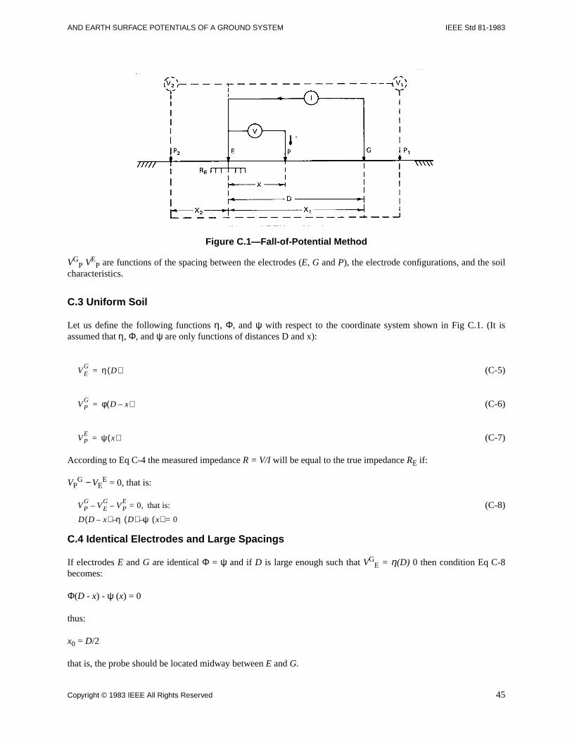
AND EARTH SURFACE POTENTIALS OF A GROUND SYSTEM IEEE Std 81-1983
Copyright © 1983 IEEE All Rights Reserved 45
Figure C.1—Fall-of-Potential Method
VGP VE
P are functions of the spacing between the electrodes (E, G and P), the electrode configurations, and the soilcharacteristics.
C.3 Uniform Soil
Let us define the following functions η, Φ, and ψ with respect to the coordinate system shown in Fig C.1. (It isassumed that η, Φ, and ψ are only functions of distances D and x):
(C-5)
(C-6)
(C-7)
According to Eq C-4 the measured impedance R = V/I will be equal to the true impedance RE if:
VPG − VE
E = 0, that is:
(C-8)
C.4 Identical Electrodes and Large Spacings
If electrodes E and G are identical Φ = ψ and if D is large enough such that VGE = η(D) 0 then condition Eq C-8
becomes:
Φ(D - x) - ψ (x) = 0
thus:
x0 = D/2
that is, the probe should be located midway between E and G.
V EG η D( )=
V PG φ D x–( )=
V PE ψ x( )=
V PG
V EG
V PE
0 that is:
D D x–( ) η D( ) ψ x( ) 0=––
,=––
IEEE Std 81-1983 IEEE GUIDE FOR MEASURING EARTH RESISTIVITY, GROUND IMPEDANCE,
C.5 Hemispherical Electrodes
If electrodes E and G are hemispheres and theft radii are small compared to x and D and if soil is uniform, then thepotential functions Φ, η and ψ are inversely proportional to the distance relative to the hemisphere center. If the originof the axes is at the center of hemisphere E then, Eq C-8 becomes:
(C-9)
The positive root of Eq C-9 is the exact potential probe location xo:
x0 = 0.618 D
This is the usual 61.8% rule [B8]. If the potential probe P is at location P2 (E side, see Fig C.1) then D − x should bereplaced by D + x in Eq C-9. In this case the equation has complex roots only. If P is at location P1 (G side, see Fig C.1)then D − x should be replaced by x − D in Eq C-9. The positive root of Eq C-9 is:
x0 = 1.618 D
C.6 General Case
If the soil is not uniform or electrodes E and G have complex configurations, or both, then, the functions Φ, η and ψare not easy to calculate. In such cases, computer solutions are generally required [B14].
1 D x–( ) 1 D 1 x 0=⁄–⁄–⁄
46 Copyright © 1983 IEEE All Rights Reserved
AND EARTH SURFACE POTENTIALS OF A GROUND SYSTEM IEEE Std 81-1983
Annex D Bibliography
(Informative)
[B1] ARMSTRONG, H. R., and SIMPKIN, L, P. Ground Electrode Potential Gradients from Model Tests, AIEETransactions, 1959, vol 78, Part III.
[B2] BARNES, H. E. US National Academy of Sciences, National Research Council Bulletin, 1952, no 65.
[B3] BELLASCHI, P. L., ARMINGTON, R. E., and SNOWDEN, A. E. Impulse and 60 Cycle Driven Grounds, II,AIEE Transactions, 1942, vol 61, pp 349.
[B4] BELLASCHI, P. L. Impulse and 60 Cycle Characteristics of Driven Grounds, AIEE Transactions, Mar 1941, vol60, pp 123-128.
[B5] BERGER, K. The Behavior of Earth Connections Under Intensity Impulse Currents, CIGRE 1946 Session,Paper no 215.
[B6] Getting Down to Earth, James G. Biddle Co, Pub 25-J.
[B7] BODIER, G. Personal Safety and Distribution Substation Grounding, (in French) Bulletin de la SociétéFrancaise des Electriciens, Oct. 1947, 6iéme séries, vol III, no 74, pp 545-562.
[B8] CURDTS, E. B. Some of the Fundamental Aspects of Ground Resistance Measurements, AIEE Transactions,1958, vol 77, Part I, pp 760.
[B9] DAWALIBI, F., and MUKHEDKAR, D. Transferred Earth Potentials in Power Systems, IEEE Transactions,Jan 30-Feb 4, 1977, Paper no F 77 196-9, IEEE Power Engineering Society Winter meeting, New York, NY.
[B10] DAWILIBI, F. and MUKHEDKAR, D. Optimum Design of Substation Grounding in Two Layer EarthStructure, Part I, Analytical Study, IEEE Transaction, Mar/Apr 1975, Power Apparatus Systems—94, no 2, pp 252-261.
[B11] DAWILIBI, F., and MUKHEDKAR, D. Sur les conditions de simulation des mises a la terre, Mars 1974, RevueGénérale d'Electricité, Tome 83, no 3.
[B12] DAWALIBI, F., and MUKHEDKAR, D. Ground Electrode Resistance Measurement in Non-Uniform Soils,IEEE Transactions, Jan 1974, vol PAS—93, no 1, pp 109-116.
[B13] DAWALIBI, F., and MUKHEDKAR, D. Modelling of Potential Distribution Around a Grounding Electrode,IEEE Transactions, Sept 1973, vol 02, no 5, pp 1455-59.
[B14] DAWALIBI, F., and MUKHEDKAR, D. Resistance Measurement of Large Grounding Systems, IEEE paperF79656—0, IEEE Power Engineering Society Meeting, Vancouver 1979.
[B15] DEVGAN, S.S., WHITEHEAD, E. R. Analytical Models for Distributed Grounding Systems, IEEETransactions, Sept/Oct, vol PAS—73, pp 1763-1770.
[B16] DUKE, C. A., and SMITH, L. E. The Technique and Instrumentation of Low Impedance GroundMeasurements, AIEE Transactions . 1958, vol 77, part I, pp 767.
[B17] ENDRENYI, Janos, Evaluation of Resistivity Tests for Design of Station Grounds in Non-Uniform Soil, IEEETransactions, Dec 1963, Power Apparatus Systems, pp 966-970.
Copyright © 1983 IEEE All Rights Reserved 47
IEEE Std 81-1983 IEEE GUIDE FOR MEASURING EARTH RESISTIVITY, GROUND IMPEDANCE,
[B18] ENDRENYI, J. Evaluation of Resistivity Tests for Design of Station Grounds in Nonuniform Soil, AIEETransactions, 1963, pp 966-970.
[B19] FADEEV, D. K., and FADDEEVA, V. N. Computational Methods of Linear Algebra, 1963, W. H. Freeman &Co, San Francisco.
[B20] GIAO, T. N., and SARMA, M.P. Effect of Two Layer Earth on the Electrical Field Near HVDC Electrodes,IEEE Transactions, Nov 1972, vol Power Apparatus Systems 01, no 6, pp 2346-65.
[B21] GISH, O. H., and W. J. ROONEY, Measurement of Resistivity of Large Masses of Undisturbed Earth,Terrestrial Magnetism and Atmospheric Electricity.
[B22] HALL, R. Substation Ground Resistance Measurements Low-Voltage Testing Techniques, 1976, IEEE PaperA76—460—6/76, IEEE Summer Power Meeting, Portland.
[B23] Harrison, L. H. The Effect of Reactive Components in the Measurement of Grounding Circuits, 1953, AIEETransactions, vol 72, Part II, pp 340-345.
[B24] KINYON, Allen L. Earth Resistivity Measurements for- Grounding Grids, Dec 1961, AIEE Transactions,pp 795-800.
[B25] KOCK, W. Grounding Method for High Voltage Stations with Grounded Neutrals, Electronische Zeit, Feb1950, vol 71, no 4, pp 89-91.
[B26] KOUTEYNIKOFF, P. Numerical Computation of the Grounding Resistance of Substations and Towers, May/June 1980, IEEE Transactions, vol Power Apparatus Systems 99, no 3, pp 957-965.
[B27] KUUSSAARI, M., and PESONEN, A. J. Earthing Impedance Measurements of Substations, CIGRE 1978,paper no 36—02.
[B28] LANCASTER—JONES, E. The Earth-Resistivity Method of Electrical Prospecting. The Mining Magazine,June 1930.
[B29] LANGER, H. Measurement of Ground Potentials in a 230 kV Substation, Electrotechnische Zeit, Feb 11,1954, ed A, vol 75, no 4.
[B30] LARSEN, S. L., and NORDELL, D. E. The Measurement of Substation Ground Resistance and Its Use inDetermining Protection for Metallic Communication Circuits, IEEE Transactions, Sept/Oct, vol 75, Power ApparatusSystems, pp 1666-1673.
[B31] IEEE Std 80-1976, IEEE Guide for Safety in Substation Grounding.
[B32] MANNHEIM, J. U., and LEUTERSHAUSEN, High Frequency Resistance Measuring Instrument, BrownBoveri and Pub BBC—Nachrichten no 3/67, pp 132-135.
[B33] MUKHEDKAR, D., and GAGNON, G. Earth Resistivity Measurements in a Two Layer Earth Structure. Jan27-Feb 1, 1974, IEEE Paper C-74-196-2. IEEE Power Engineering Society Winter Meeting, New York, NY.
[B34] NORINDER, H., and PETROPOULOS, G. Characteristics of Pointed Electrodes and Direct Strokes in SurgeCurrents to Ground, CIGRE 1948, paper no 310.
[B35] PALMER, L. S. Examples of Geoelectric Surveys, June 1959, IEE vol 106, Part A.
[B36] RUDENBERG, R. Fundamental Considerations on Ground Currents, Electrical Engineering, Jan 1945, vol 64.
48 Copyright © 1983 IEEE All Rights Reserved
AND EARTH SURFACE POTENTIALS OF A GROUND SYSTEM IEEE Std 81-1983
[B37] SELJESETH, H., CAMPLING, A., FEIST, J. H., and KUUSSAARI, M. Station Earthing — Safety andInterferences, CIGRE Study Committees Electra, July 1980, no 71, pp 47-69.
[B38] SUNDE, E. D. Earth Conduction Effects in Transmission Systems, New York, Dover Publications, 1968.
[B39] THUG, G. F. Earth Resistances, London, Georges Newnes Limited, 1964.
[B40] THUG, G. F. Measurement of the Resistance of an Earth Electrode System Covering a Large Area, IEEEProceedings, March 1969, vol 116, no 3.
[B41] THUG, G. F. Measurements of Earth Electrode with Particular References to Earth Electrode Systems Coveringa Large Area, IEEE Proceedings, Dec 1964, vol 111, no 12, pp 2118-2130.
[B42] THAPAR, B., and GROSS, E. T. B. Grounding Grids for High-Voltage Stations, Part IV, Resistance ofGrounding Grids in Non Uniform Soil, IEEE Transactions, Oct 1963, Power Apparatus Systems vol 82, pp 782-788.
[B43] WENNER, F. A Method of Measuring Resistivity, National Bureau of Standards, Scientific Paper, 1916, 12, noS—258, pp 469.
[B44] WHITEHEAD, L. E. Nomograph Determine Ground—Rod Resistance, Electric Light and Power, Dec 1962.
Copyright © 1983 IEEE All Rights Reserved 49