ANSI E1.20 - 2010 Entertainment Technology RDM Remote Device … · 2015-06-21 · ANSI E1.20 -...
148
ANSI E1.20 - 2010 Entertainment Technology RDM Remote Device Management Over DMX512 Networks
Transcript of ANSI E1.20 - 2010 Entertainment Technology RDM Remote Device … · 2015-06-21 · ANSI E1.20 -...

ANSI E1.20 - 2010
Entertainment Technology
RDM
Remote Device Management
Over DMX512 Networks

[blank page]

ANSI E1.20 - 2010
Entertainment Technology
RDM
Remote Device Management
Over DMX512 Networks
Copyright 2011 PLASA NA. All rights reserved.
CP/2009-1017r2
Approved as an American National Standard by the ANSI Board of Standards Review on 4 January 2011.

ANSI E1.20 – 2010, Entertainment Technology – RDM – Remote Device Management over DMX512 Networks
CP/2009-1017r2 -i- Copyright 2011 PLASA NA
Notice and Disclaimer
PLASA does not approve, inspect, or certify any installations, procedures, equipment or materials for compliance with codes, recommended practices or standards. Compliance with an PLASA standard or recommended practice is the sole and exclusive responsibility of the manufacturer or provider and is entirely within their control and discretion. Any markings, identification, or other claims of compliance do not constitute certification or approval of any type or nature whatsoever by PLASA.
PLASA neither guarantees nor warrants the accuracy or completeness of any information published herein and disclaim liability for any personal injury, property or other damage or injury of any nature whatsoever, whether special, indirect, consequential or compensatory, directly or indirectly resulting from the publication, use of, or reliance on this document.
In issuing and distributing this document, PLASA does not either (a) undertake to render professional or other services for or on behalf of any person or entity, or (b) undertake any duty to any person or entity with respect to this document or its contents. Anyone using this document should rely on his or her own independent judgment or, as appropriate, seek the advice of a competent professional in determining the exercise of reasonable care in any given circumstance.

ANSI E1.20 – 2010, Entertainment Technology – RDM – Remote Device Management over DMX512 Networks
CP/2009-1017r2 -ii- Copyright 2011 PLASA NA
Published By: PLASA North America
630 Ninth Avenue, Suite 609
New York, NY 10036
USA
Phone: 1-212-244-1505
Fax: 1-212-244-1502
Email: [email protected]
For additional copies of this document contact: The ESTA Foundation
630 Ninth Avenue, Suite 609
New York, NY 10036
USA
Phone: 1-212-244-1505
Fax: 1-212-244-1502
http://www.estafoundation.org
The PLASA Technical Standards Program
The PLASA Technical Standards Program was created to serve the PLASA membership and the entertainment industry in technical standards related matters. The goal of the Program is to take a leading role regarding technology within the entertainment industry by creating recommended practices and standards, monitoring standards issues around the world on behalf of our members, and improving communications and safety within the industry. PLASA works closely with the technical standards efforts of other organizations within our industry, including USITT and VPLT, as well as representing the interests of PLASA members to ANSI, UL, and the NFPA. The Technical Standards Program is accredited by the American National Standards Institute.
The Technical Standards Council (TSC) was established to oversee and coordinate the Technical Standards Program. Made up of individuals experienced in standards-making work from throughout our industry, the Council approves all projects undertaken and assigns them to the appropriate working group. The Technical Standards Council employs a Technical Standards Manager to coordinate the work of the Council and its working groups as well as maintain a ―Standards Watch‖ on behalf of members. Working groups include: Camera Cranes, Control Protocols, Electrical Power, Floors, Fog and Smoke, Followspot Position, Photometrics, Rigging, and Stage Lifts.
PLASA encourages active participation in the Technical Standards Program. There are several ways to become involved. If you would like to become a member of an existing working group, as have over four hundred people, you must complete an application which is available from the PLASA office. Your application is subject to approval by the working group and you will be required to actively participate in the work of the group. This includes responding to letter ballots and attending meetings. Membership in PLASA is not a requirement. You can also become involved by requesting that the TSC develop a standard or a recommended practice in an area of concern to you.
The Control Protocols Working Group, which authored this Standard, consists of a cross section of entertainment industry professionals representing a diversity of interests. PLASA is committed to developing consensus-based standards and recommended practices in an open setting.

ANSI E1.20 – 2010, Entertainment Technology – RDM – Remote Device Management over DMX512 Networks
CP/2009-1017r2 -iii- Copyright 2011 PLASA NA
Table of Contents
Introduction ............................................................................................................................. 1
Overview .................................................................................................................................. 1
1 Normative References ......................................................................................................... 3
2 Physical Layer ...................................................................................................................... 4
2.1 General...................................................................................................................................... 4
2.2 Electrical Specifications and Physical Layer Overview ........................................................ 4 2.2.1 ANSI E1.11 - EF1.0 ................................................................................................................................4
2.3 Termination Requirements ...................................................................................................... 4
2.4 Maintaining data link state between packets ......................................................................... 5 2.4.1 Line Bias Networks .................................................................................................................................5
2.5 Command port reference circuit ............................................................................................. 6 2.5.1 Details of the reference circuit. ...............................................................................................................6
2.6 Default line state control ......................................................................................................... 7
3 Timing ................................................................................................................................... 8
3.1 Controller Timing Requirements ............................................................................................. 8 3.1.1 Controller Packet Timing .........................................................................................................................8 3.1.2 Controller Packet spacing .......................................................................................................................9 3.1.3 Driver shutoff time ................................................................................................................................ 10
3.2 Responder Timing Requirements ......................................................................................... 10 3.2.1 Responder Packet Timings .................................................................................................................. 10 3.2.2 Responder Packet spacing .................................................................................................................. 11 3.2.3 Responder discovery response driver enable time ............................................................................. 11 3.2.4 Driver shutoff time ................................................................................................................................ 11 3.2.5 Discovery Response MARK time ......................................................................................................... 11
3.3 Data collisions ........................................................................................................................ 12
4 In-Line Devices .................................................................................................................. 12
4.1 Overview ................................................................................................................................. 12 4.1.1 Transparent In-Line devices ................................................................................................................ 12
4.2 Transparent In-Line Device Timing Requirements .............................................................. 12 4.2.1 Port Turnaround ................................................................................................................................... 13 4.2.2 Data Delay ........................................................................................................................................... 13 4.2.3 Bit Distortion ......................................................................................................................................... 13 4.2.4 BREAK timing ...................................................................................................................................... 14
4.3 In-Line devices operating as part of Non-RDM system ....................................................... 14
4.4 In-line Devices as Responders .............................................................................................. 14
5 Device Addressing............................................................................................................. 15
5.1 General.................................................................................................................................... 15
5.2 UID Text Representation ........................................................................................................ 15

ANSI E1.20 – 2010, Entertainment Technology – RDM – Remote Device Management over DMX512 Networks
CP/2009-1017r2 -iv- Copyright 2011 PLASA NA
5.3 Broadcast Message Addressing ........................................................................................... 16
5.4 Responders with multiple Responder Ports in a single Device. ......................................... 16
6 Message Structure ............................................................................................................. 17
6.1 Byte Ordering ......................................................................................................................... 17
6.2 Packet Format ........................................................................................................................ 17 6.2.1 START Code ........................................................................................................................................ 18 6.2.2 Sub START Code ................................................................................................................................ 18 6.2.3 Message Length .................................................................................................................................. 18 6.2.4 Destination UID .................................................................................................................................... 19 6.2.5 Source UID........................................................................................................................................... 19 6.2.6 Transaction Number (TN) .................................................................................................................... 19 6.2.7 Port ID / Response Type ...................................................................................................................... 19 6.2.8 Message Count .................................................................................................................................... 20 6.2.9 Sub-Device Field .................................................................................................................................. 22 6.2.10 Message Data Block (MDB)............................................................................................................... 22 6.2.11 Checksum .......................................................................................................................................... 24
6.3 Response Type Field Values ................................................................................................. 25 6.3.1 Acknowledge (RESPONSE_TYPE_ACK) ........................................................................................... 25 6.3.2 Acknowledge Overflow (RESPONSE_TYPE_ACK_OVERFLOW) ..................................................... 25 6.3.3 Acknowledge Timer (RESPONSE_TYPE_ACK_TIMER) .................................................................... 27 6.3.4 Negative Acknowledge (RESPONSE_TYPE_NACK_REASON) ........................................................ 29
7 Discovery Method .............................................................................................................. 30
7.1 General.................................................................................................................................... 30
7.2 Binary Search Tree ................................................................................................................ 30
7.3 Discovery Process Steps ...................................................................................................... 31
7.4 Discovery Mute Flag .............................................................................................................. 31 7.4.1 Clearing of Mute Flag ........................................................................................................................... 31
7.5 Discovery Unique Branch Message (DISC_UNIQUE_BRANCH) ......................................... 32 7.5.1 Response Unique Branch Message Decoding by Controller .............................................................. 34 7.5.2 Collisions .............................................................................................................................................. 34
7.6 Discovery Mute/Un-Mute Messages ...................................................................................... 34 7.6.1 Control Field ......................................................................................................................................... 34 7.6.2 Binding UID .......................................................................................................................................... 35 7.6.3 Discovery Mute Message (DISC_MUTE) ............................................................................................ 35 7.6.4 Discovery Un-Mute Message (DISC_UN_MUTE) ............................................................................... 36
7.7 Discovery Algorithm .............................................................................................................. 37
7.8 Ongoing Device Discovery .................................................................................................... 39
8 Proxy Devices .................................................................................................................... 40
8.1 General.................................................................................................................................... 40
8.2 Discovery ................................................................................................................................ 40 8.2.1 Represented Devices ........................................................................................................................... 40 8.2.2 Proxy Management .............................................................................................................................. 40

ANSI E1.20 – 2010, Entertainment Technology – RDM – Remote Device Management over DMX512 Networks
CP/2009-1017r2 -v- Copyright 2011 PLASA NA
8.3 Response Messages .............................................................................................................. 40
8.4 Proxy Management Messages .............................................................................................. 41 8.4.1 Get Proxied Device Count (PROXIED_DEVICE_COUNT) ................................................................. 41 8.4.2 Get Proxied Devices (PROXIED_DEVICES) ....................................................................................... 42
9 Sub-Devices ....................................................................................................................... 43
9.1 General.................................................................................................................................... 43
9.2 Sub-Device Messages ............................................................................................................ 43 9.2.1 Sub-Device Field .................................................................................................................................. 43 9.2.2 Using Sub-Devices .............................................................................................................................. 43 9.2.3 Required Sub-Device Messages ......................................................................................................... 43
10 RDM Parameter Messages .............................................................................................. 44
10.1 Text Field Handling .............................................................................................................. 44
10.2 Network Management Messages ........................................................................................ 44 10.2.1 Communication Status (COMMS_STATUS) ..................................................................................... 44
10.3 Collection of Queued and Status Messages ...................................................................... 46 10.3.1 Get Queued Message (QUEUED_MESSAGE) ................................................................................. 46 10.3.2 Get Status Messages (STATUS_MESSAGES)................................................................................. 49 10.3.3 Get Status ID Description (STATUS_ID_DESCRIPTION) ................................................................ 52 10.3.4 Clear Status ID (CLEAR_STATUS_ID) ............................................................................................. 52 10.3.5 Get/Set Sub-Device Status Reporting Threshold (SUB_DEVICE_STATUS_REPORT_THRESHOLD) ................................................................................... 53
10.4 RDM Information Messages ................................................................................................ 54 10.4.1 Get Supported Parameters (SUPPORTED_PARAMETERS) ........................................................... 54 10.4.2 Get Parameter Description (PARAMETER_DESCRIPTION) ............................................................ 56
10.5 Product Information Messages ........................................................................................... 58 10.5.1 Get Device Info (DEVICE_INFO) ....................................................................................................... 58 10.5.2 Get Product Detail ID List (PRODUCT_DETAIL_ID_LIST) ............................................................... 61 10.5.3 Get Device Model Description (DEVICE_MODEL_DESCRIPTION) ................................................. 62 10.5.4 Get Manufacturer Label (MANUFACTURER_LABEL) ...................................................................... 62 10.5.5 Get/Set Device Label (DEVICE_LABEL) ........................................................................................... 63 10.5.6 Get/Set Factory Defaults (FACTORY_DEFAULTS) .......................................................................... 64 10.5.7 Get Language Capabilities (LANGUAGE_CAPABILITIES) ............................................................... 65 10.5.8 Get/Set Language (LANGUAGE) ...................................................................................................... 66 10.5.9 Get Software Version Label (SOFTWARE_VERSION_LABEL) ....................................................... 67 10.5.10 Get Boot Software Version ID (BOOT_SOFTWARE_VERSION_ID).............................................. 68 10.5.11 Get Boot Software Version Label (BOOT_SOFTWARE_VERSION_LABEL) ................................. 69
10.6 DMX512 Setup Messages .................................................................................................... 69 10.6.1 Get/Set DMX512 Personality (DMX_PERSONALITY) ...................................................................... 69 10.6.2 Get DMX512 Personality Description (DMX_PERSONALITY_DESCRIPTION) ............................... 71 10.6.3 Get/Set DMX512 Starting Address (DMX_START_ADDRESS) ....................................................... 72 10.6.4 Get Slot Info (SLOT_INFO)................................................................................................................ 73 10.6.5 Get Slot Description (SLOT_DESCRIPTION) ................................................................................... 74 10.6.6 Get Default Slot Value (DEFAULT_SLOT_VALUE) .......................................................................... 75
10.7 Sensor Parameter Messages ............................................................................................... 75 10.7.1 Get Sensor Definition (SENSOR_DEFINITION) ............................................................................... 76

ANSI E1.20 – 2010, Entertainment Technology – RDM – Remote Device Management over DMX512 Networks
CP/2009-1017r2 -vi- Copyright 2011 PLASA NA
10.7.2 Get/Set Sensor (SENSOR_VALUE) .................................................................................................. 78 10.7.3 Record Sensors (RECORD_SENSORS) .......................................................................................... 80
10.8 Power/Lamp Setting Parameter Messages ......................................................................... 81 10.8.1 Get/Set Device Hours (DEVICE_HOURS) ........................................................................................ 81 10.8.2 Get/Set Lamp Hours (LAMP_HOURS) .............................................................................................. 82 10.8.3 Get/Set Lamp Strikes (LAMP_STRIKES) .......................................................................................... 83 10.8.4 Get/Set Lamp State (LAMP_STATE) ................................................................................................ 84 10.8.5 Get/Set Lamp On Mode (LAMP_ON_MODE) ................................................................................... 85 10.8.6 Get/Set Device Power Cycles (DEVICE_POWER_CYCLES)........................................................... 86
10.9 Display Setting Parameter Messages ................................................................................. 87 10.9.1 Get/Set Display Invert (DISPLAY_INVERT) ...................................................................................... 87 10.9.2 Get/Set Display Level (DISPLAY_LEVEL) ........................................................................................ 88
10.10 Device Configuration Parameter Messages ..................................................................... 89 10.10.1 Get/Set Pan Invert (PAN_INVERT) ................................................................................................. 89 10.10.2 Get/Set Tilt Invert (TILT_INVERT) ................................................................................................... 90 10.10.3 Get/Set Pan/Tilt Swap (PAN_TILT_SWAP) ..................................................................................... 91 10.10.4 Get/Set Device Real-Time Clock (REAL_TIME_CLOCK) ............................................................... 92
10.11 Device Control Parameter Messages ................................................................................ 93 10.11.1 Get/Set Identify Device (IDENTIFY_DEVICE) ................................................................................. 93 10.11.2 Reset Device (RESET_DEVICE) ..................................................................................................... 94 10.11.3 Get/Set Power State (POWER_STATE) ......................................................................................... 95 10.11.4 Get/Set Perform Self Test (PERFORM_SELFTEST) ...................................................................... 96 10.11.5 Get Self Test Description (SELF_TEST_DESCRIPTION) .............................................................. 97 10.11.6 Capture Preset (CAPTURE_PRESET) ............................................................................................ 98 10.11.7 Get/Set Preset Playback (PRESET_PLAYBACK) ........................................................................... 99
11 Operational Issues ......................................................................................................... 101
11.1 Polling Intervals ................................................................................................................. 101
12 Protocol Support Issues ............................................................................................... 101
Appendix A: Defined Parameters (Normative) ................................................................. 102
Appendix B: Status Message ID’s (Normative) ................................................................ 118
Appendix C: Slot Info (Normative)..................................................................................... 120
Appendix D: Definitions (Normative) ................................................................................ 122
Appendix E: Discovery Pseudo-Code Example (Informative) ........................................ 126
E.1 Find Devices Function Call ................................................................................................. 126
E.2 Find Devices Pseudo-Code ................................................................................................. 126
Appendix F: Qualification tests for transmitter/receiver circuits used in RDM systems (Normative) .......................................................................................................................... 129
F.1 Qualification Tests for Command port Transmitter Circuits ............................................. 129 F.1.1 Notes on Figure F-1 ........................................................................................................................... 129
F.2 Output tests for testing transmitters / line bias networks for RDM command ports ...... 130
F.3 Line loading tests for command ports ............................................................................... 130

ANSI E1.20 – 2010, Entertainment Technology – RDM – Remote Device Management over DMX512 Networks
CP/2009-1017r2 -vii- Copyright 2011 PLASA NA
F.4 Notes on the responder test circuit .................................................................................... 132
F.5 Testing Responder Transmitters ........................................................................................ 132
Contact Information ............................................................................................................ 133
Acknowledgments: ............................................................................................................. 134

ANSI E1.20 – 2010, Entertainment Technology – RDM – Remote Device Management over DMX512 Networks
CP/2009-1017r2 -viii- Copyright 2011 PLASA NA
List of Tables
Table 2-1: Command Port Reference Circuit Values ................................................................ 7
Table 3-1: Controller Packet Timing ......................................................................................... 8
Table 3-2: Controller Packet Spacing Times ............................................................................. 9
Table 3-3: Responder Packet Timing ..................................................................................... 10
Table 3-4: Responder Packet Spacing Times ......................................................................... 11
Table 5-1: Unique ID (UID) Format ......................................................................................... 15
Table 6-1: Byte Ordering ......................................................................................................... 17
Table 6-2: Packet Format ....................................................................................................... 17
Table 6-3: Example of Packet showing Message Length Pointer to Checksum ..................... 18
Table 6-4: Message Data Block (MDB) Format ...................................................................... 22
Table 6-5: Command Class Description ................................................................................. 22
Table 6-6: Checksum Usage Example.................................................................................... 24
Table 6-7: Response Type Field Allowable Values from Responder ...................................... 25
Table 6-8: Key for Table 6-7 ................................................................................................... 25
Table 7-1: DISC_UNIQUE_BRANCH Response Packet Encoding ........................................ 33
Table 7-2: DISC_UNIQUE_BRANCH Response Packet Decoding ........................................ 34
Table 7-3: Control Field .......................................................................................................... 34
Table 10-1: Required Response to Status Requests .............................................................. 51
Table 10-2: Date and Time Ranges ........................................................................................ 93
Table A-1: Command Class Defines ..................................................................................... 102
Table A-2: Response Type Defines ...................................................................................... 102
Table A-3: RDM Categories/Parameter ID Defines .............................................................. 103
Table A-4: Status Type Defines ............................................................................................ 104
Table A-5: Product Category Defines ................................................................................... 105
Table A-6: Product Detail Defines ......................................................................................... 107
Table A-7: Preset Playback Defines ..................................................................................... 111
Table A-8: Lamp State Defines ............................................................................................. 111
Table A-9: Lamp On Mode Defines ...................................................................................... 111
Table A-10: Self Test Defines ............................................................................................... 112
Table A-11: Power State Defines .......................................................................................... 112
Table A-12: Sensor Type Defines ......................................................................................... 112
Table A-13: Sensor Unit Defines .......................................................................................... 114
Table A-14: Sensor Unit Prefix Defines ................................................................................ 115
Table A-15: Data Type Defines ............................................................................................. 116
Table A-16 Parameter Description Command Class Defines ............................................... 116
Table A-17: Response NACK Reason Code Defines ........................................................... 117
Table B-1: Status Message Markers ..................................................................................... 118
Table B-2: Status Message ID Definitions ............................................................................ 118
Table C-1: Slot Type ............................................................................................................. 120
Table C-2: Slot ID Definitions ................................................................................................ 120

ANSI E1.20 – 2010, Entertainment Technology – RDM – Remote Device Management over DMX512 Networks
CP/2009-1017r2 -ix- Copyright 2011 PLASA NA
List of Figures
Figure 2-1: Command Port Reference Circuit ........................................................................... 6
Figure 4-2: Bit Asymmetrical Delay ......................................................................................... 13
Figure 7-1: Binary Search ....................................................................................................... 30
Figure 7-2: Device Discovery Process .................................................................................... 38
Figure F-1: Command Port Transmitter Test Circuit ............................................................. 129
Figure F-2: Command Port Load Test Circuit ....................................................................... 130
Figure F-3: Calibration Circuit ............................................................................................... 131
Figure F-4: Responder Test Circuit ....................................................................................... 132

ANSI E1.20 – 2010, Entertainment Technology – RDM – Remote Device Management over DMX512 Networks
CP/2009-1017r2 -1- Copyright 2011 PLASA NA
Introduction
The Remote Device Management Protocol (RDM) permits intelligent bi-directional communication between devices from multiple manufacturers utilizing a modified DMX512 data link. RDM is an EF 1.0 implementation of ANSI E1.11.
RDM permits a console or other controlling device to discover and then configure, monitor, and manage intermediate and end-devices connected through a DMX512 network. RDM provides for intelligent control of devices on a DMX512 network, which has not been previously available outside of proprietary networks.
This standard specifies: the physical layer and timings, device discovery process and algorithms, message structure and communication.
Overview
This document specifies the physical layer requirements for handling half-duplex bi-directional communication and the timings associated with bi-directional communication.
This document addresses requirements for controllers, end devices, and In-Line devices such as DMX512 splitters/mergers and distribution systems to implement or support RDM communication.
An RDM system functions as a polled system, meaning that no intermediate or end-device will initiate communication. Only the device acting as the controller shall have the capability to initiate a response from any RDM device.
The RDM protocol makes use of an Alternate START Code (ASC) as defined in ANSI E1.11, to establish communication on a conventional DMX512 link. The first step in the RDM process is for a controller to identify all the devices that are connected to the data link. This is accomplished by performing a binary-tree search, or other type of search, to identify the internal Unique ID (UID) of all the connected devices.
Once a device has been discovered, the controller can request status messages, or get and set device parameters such as the DMX512 Address. All messages sent are addressed to the UID of the targeted device or through one of the Broadcast UID addresses.
Devices that primarily act as controllers (and distribution devices that do their own "discovery") shall be referred to as controllers in this document. Devices that typically receive and act on DMX512 data and/or act on RDM messages shall be referred to as responding devices or responders. Controllers send requests and receive responses on their command port. Responders receive commands and send responses on their response port. An in-line device will typically have one response port to receive commands and NULL START CODE packets from the controller, and one or more command ports of their own to forward this data to their responders.
Only one controller can be active on a given DMX512 link at any one time.
During normal operation, it is expected that the Discovery and Parameter messages will be interspersed with normal NULL START Code DMX512 packets.

ANSI E1.20 – 2010, Entertainment Technology – RDM – Remote Device Management over DMX512 Networks
CP/2009-1017r2 -3- Copyright 2011 PLASA NA
1 Normative References
ANSI E1.11-2004 Entertainment Technology -- USITT DMX512-A --
Asynchronous Serial Digital Data Transmission Standard for Controlling Lighting Equipment and Accessories.
Originally published by the Entertainment Services and Technology Association (ESTA), now PLASA North America
630 Ninth Avenue, Suite 609
New York, NY 10036
USA
1-212-244-1505
http://tsp.plasa.org
ANSI/TIA/EIA-485-A-1998 Electrical Characteristics of Generators & Receivers for Use in
Balanced Digital Multipoint Systems This standard will be referred to as EIA-485-A in this document. Electronics Industries Alliance 2500 Wilson Boulevard Arlington , VA 22201-3834 USA 1-703-907-7500 http://www.eia.org/
Telecommunications Industry Association 2500 Wilson Blvd., Suite 300 Arlington, VA 22201 USA 1-703- 907-7700 fax: 1-703-907-7727 http://www.tiaonline.org/
Note: EIA-485-A is compatible with: ISO/IEC 8482:1993 Information Technology - Telecommunications and information exchange between systems - Twisted pair multipoint interconnections.
ISO/IEC 646 Information Technology - ISO 7-bit Coded Character Set for Information Interchange ISO 639-1 Codes for the representation of names of languages –
Part 1: Alpha-2 code
IEC International Electrotechnical Commission PO Box 131 3 rue de Varembe 1211 Geneva 20 Switzerland 41 22 919 02 11 www.iec.ch
ISO International Organization for Standardization 1, Rue de Varembe Case Postale 56 CH-1211 Geneva 20 Switzerland 41 22 74 901 11 www.iso.ch

ANSI E1.20 – 2010, Entertainment Technology – RDM – Remote Device Management over DMX512 Networks
CP/2009-1017r2 -4- Copyright 2011 PLASA NA
2 Physical Layer
E1.20 (RDM) is an extension to E1.11 (DMX512-A). A key goal of this standard is to allow the use of new and legacy DMX512 receiving devices in mixed systems with new E1.20 equipment and to provide a straightforward path to upgrade existing DMX512 distribution systems for support of the E1.20 protocol. The use of E1.20 devices in an E1.11 system will not compromise any E1.11 functionality.
The physical layer requirements of E1.20 are based on those of E1.11, with additional requirements related to bidirectional communication. Both developers and users must take note of these additional requirements in order to implement reliable E1.20 systems.
The electrical specification of this Standard conforms to E1.11 (DMX512-A), except where specifically stated in this document. The E1.11 electrical specification is based on ANSI/TIA/EIA-485-A-1998. Where a conflict exists between E1.11 or ANSI/TIA/EIA-485-A-1998 and this document, this document is controlling as far as this standard is concerned.
2.2.1 ANSI E1.11 - EF1.0
Systems that comply with this standard fall within the scope of E1.11 Annex B - EF1. Systems that send data in both directions on the primary data link are classified as EF1. These systems shall use the primary data link for both the NULL START Code DMX512 packets and also return data controlled by the use of Alternate START Code packets.
Use of the secondary data link is beyond the scope of this standard.
One end of the primary data link shall be terminated as specified in E1.11.
The other end of the primary data link shall be terminated by a line biasing network. The requirements for line biasing networks are in Sections 2.4 and 2.5.
Command ports shall include the line biasing network.
Command ports may be designed with means to disconnect the line biasing network. In this configuration a line biasing network shall be provided by other means.
2.1 General
2.2 Electrical Specifications and Physical Layer Overview
2.3 Termination Requirements

ANSI E1.20 – 2010, Entertainment Technology – RDM – Remote Device Management over DMX512 Networks
CP/2009-1017r2 -5- Copyright 2011 PLASA NA
RDM systems use bidirectional half duplex operation. All command ports and responder ports are fitted with a transmitter and a receiver (e.g. a transceiver). Once a system is configured, only one transmitter is in the transmit mode at any one time. Typically, there may be considerable time when all transmitters are in a high impedance state. It is imperative that the data link shall maintain a marking state between packets, even if all transmitters are disabled.
To ensure this:
1.) A transmitter shall place the data link in a marking state at least 4µs before placing the line in a high impedance state.
2.) A transmitter shall begin driving the line in a marking condition.
3.) A Command port located at the end of a data link shall employ a line bias network as
detailed in Section 2.4.1.
4.) A Command port not located at an end of the data link shall not employ the line bias
network of Section 2.4.1. Means of termination and biasing of such systems is beyond the scope of this standard.
2.4.1 Line Bias Networks
The command port shall provide a means to bias the termination of the data link to a value of at least 245 mV and verified by using the test circuit described in Appendix F. This means may be disabled for special applications. If the line biasing network is enabled, the differential input impedance shall be 120ohms +/- 10%; however, if it is not enabled, the differential input impedance shall not be greater than one unit load.
The termination shall be polarized such that Data+ of the data link is positive with respect to Data- of the data link. The Line Biasing network shall maintain this bias when the data link is loaded with the equivalent of 32 unit loads and common mode voltage is varied over the range of +7 volts to -7 volts DC.
2.4 Maintaining data link state between packets

ANSI E1.20 – 2010, Entertainment Technology – RDM – Remote Device Management over DMX512 Networks
CP/2009-1017r2 -6- Copyright 2011 PLASA NA
Figure 2-1: Command Port Reference Circuit
This standard does not mandate a specific bias circuit. Figure 2-1 is provided as a reference.
Key for Figure 2-1:
1) Data link common (0 Volt DC)
2) Data-
3) Data+
A) +5 Volt DC supply
U1) EIA485 transceiver
B, C) Transceiver control lines
D, E) Logic level data lines
2.5.1 Details of the reference circuit.
The reference line bias network is a simple voltage divider consisting of resistors R1, Rt1 in parallel with Rt2, and R2. Rt1 is the termination at the command port. Rt2 is the terminating resistor at the opposite end of the data link. The network is connected between the Vcc power supply and supply common. The connection between R1 and Rt1 is connected to the Data+ output of the transceiver. The connection between Rt1 and R2 is connected to the Data- output of the transceiver.
The physical line bias network consists of R1, Rt1, and R2. Correct operation is dependent upon the presence of Rt2. These component values are specified in Table 2-1.
2.5 Command port reference circuit

ANSI E1.20 – 2010, Entertainment Technology – RDM – Remote Device Management over DMX512 Networks
CP/2009-1017r2 -7- Copyright 2011 PLASA NA
Table 2-1: Command Port Reference Circuit Values
R1
562 Ω 2%
R2
562 Ω 2%
Rt1
133 Ω 2%
Rt1 parallel (R1+R2) should equal 120 Ω
Rt2
120 Ω 5%
This resistor is not physically part of the line bias network. It should be located at the opposite end of the data link from the command port.
Vcc +5 VDC Resistor values above assume 5VDC operation. Other Vcc values will require new resistor value calculations.
It is recommended that Responders and In-Line devices prevent their responder ports from erroneously driving the line in case of failure.
All ports shall power up with the driver in a high impedance state.
The Line Bias network shall be enabled prior to RDM communication beginning.
2.6 Default line state control

ANSI E1.20 – 2010, Entertainment Technology – RDM – Remote Device Management over DMX512 Networks
CP/2009-1017r2 -8- Copyright 2011 PLASA NA
3 Timing
RDM systems can carry several different types of packets. Controllers can generate NULL START Code packets, RDM Alternate START Code (ASC) packets and non-RDM ASC packets.
RDM packets are compatible with DMX512 and DMX512-A timing. Certain timing requirements have been tightened to ensure correct operation of the RDM protocol.
RDM controllers generate RDM request messages that are identified by the RDM ASC. Responders can generate an RDM response, also identified by the RDM ASC, but only immediately after receiving a controller request. In general, every controller request will generate a responder response. However, there will be times, either for protocol reasons or through errors, that a controller request may not cause the generation of a device response.
Because RDM is a half duplex communications protocol, the controller must release (stop driving) the line before the responders begin to drive the line. To ensure that this ―line turn around‖ takes place properly, a certain amount of dead time has been allocated to this function. This time is relatively large to allow microcontrollers/microprocessors to disable the driver after the last byte has been sent and to allow for in-line devices that may cause timing delay.
The DISC_UNIQUE_BRANCH response message is an exception to normal timing rules, as it does not contain a BREAK or MAB. See Section 7.5 Discovery Unique Branch Message for additional details on this message.
3.1.1 Controller Packet Timing
RDM controller equipment shall conform to the timing in Table 3-1. The packet structure showing the various timing elements is represented by the Timing Diagram (Figure 5) located in E1.11.
Table 3-1: Controller Packet Timing
Break MAB Inter-slot Time Total Packet Time
Min Max Min Max Min Max Max
1 Transmit 176µs 352µs 12µs 88µs 0µs 2.0msA 440µs
B +(n
C x 44µs
D ) +
((nC -1) x 76µs
E)
2 Receive 88µs 352µs 8µs 88µs 0µs 2.1ms
Notes:
A). This is the maximum inter-slot time for any individual slot, However, the Total Packet Time requirement must be observed.
B). The 440µs in the total packet time formula is the sum of the maximum break time and maximum MAB.
C). n is the number of data slots in the packet.
D). Slot Time per ANSI E1.11.
E). The average inter-slot time shall not exceed 76µs.
All Controller generated packets, regardless of Start Code, shall conform to line one of Table 3-1. Controllers shall correctly receive packets that conform to line two of Table 3-1.
3.1 Controller Timing Requirements
ANSI E1.20 – 2010, Entertainment Technology – RDM – Remote Device Management over DMX512 Networks
CP/2009-1017r2 -9- Copyright 2011 PLASA NA
Break timing has been modified from the DMX512 standard. The minimum has been lengthened to allow In-Line devices to decrease this time as they pass the data through. The maximum break time has been set to ensure RDM command throughput and to ensure that RDM has minimal impact on the DMX512 update rate. To this end, it is recommended that the break, MAB, and inter-slot times be kept as close to the minimum as possible.
Controllers may consider responder packets with inter-slot delays exceeding the maximum defined in line 2 of Table 3-1 to be lost and may resume sending controller packets.
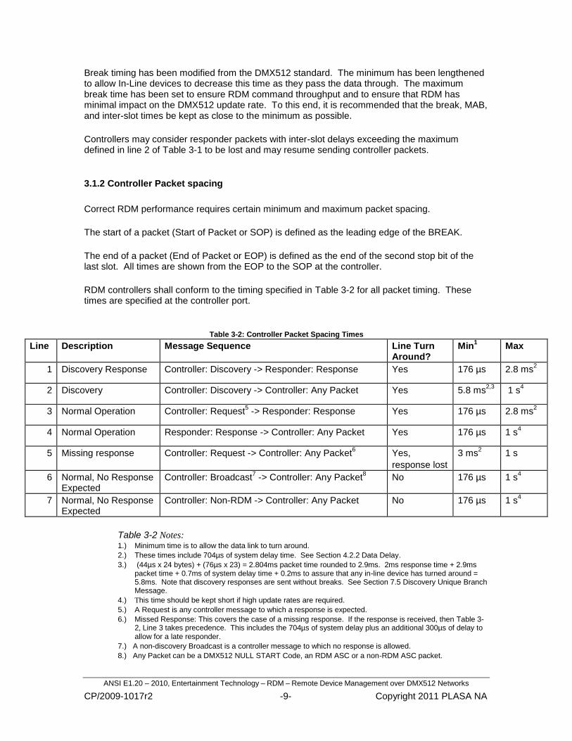
3.1.2 Controller Packet spacing
Correct RDM performance requires certain minimum and maximum packet spacing.
The start of a packet (Start of Packet or SOP) is defined as the leading edge of the BREAK.
The end of a packet (End of Packet or EOP) is defined as the end of the second stop bit of the last slot. All times are shown from the EOP to the SOP at the controller.
RDM controllers shall conform to the timing specified in Table 3-2 for all packet timing. These times are specified at the controller port.
Table 3-2: Controller Packet Spacing Times
Line Description Message Sequence Line Turn Around?
Min1 Max
1 Discovery Response Controller: Discovery -> Responder: Response Yes 176 µs 2.8 ms2
2 Discovery Controller: Discovery -> Controller: Any Packet Yes 5.8 ms2,3
1 s4
3 Normal Operation Controller: Request5 -> Responder: Response Yes 176 µs 2.8 ms
2
4 Normal Operation Responder: Response -> Controller: Any Packet Yes 176 µs 1 s4
5 Missing response Controller: Request -> Controller: Any Packet6 Yes,
response lost
3 ms2 1 s
6 Normal, No Response Expected
Controller: Broadcast7 -> Controller: Any Packet
8 No 176 µs 1 s
4
7
Normal, No Response Expected
Controller: Non-RDM -> Controller: Any Packet No 176 µs 1 s4
Table 3-2 Notes: 1.) Minimum time is to allow the data link to turn around.
2.) These times include 704µs of system delay time. See Section 4.2.2 Data Delay.
3.) (44µs x 24 bytes) + (76µs x 23) = 2.804ms packet time rounded to 2.9ms. 2ms response time + 2.9ms packet time + 0.7ms of system delay time + 0.2ms to assure that any in-line device has turned around = 5.8ms. Note that discovery responses are sent without breaks. See Section 7.5 Discovery Unique Branch Message.
4.) This time should be kept short if high update rates are required.
5.) A Request is any controller message to which a response is expected.
6.) Missed Response: This covers the case of a missing response. If the response is received, then Table 3-2, Line 3 takes precedence. This includes the 704µs of system delay plus an additional 300µs of delay to allow for a late responder.
7.) A non-discovery Broadcast is a controller message to which no response is allowed.
8.) Any Packet can be a DMX512 NULL START Code, an RDM ASC or a non-RDM ASC packet.
ANSI E1.20 – 2010, Entertainment Technology – RDM – Remote Device Management over DMX512 Networks
CP/2009-1017r2 -10- Copyright 2011 PLASA NA
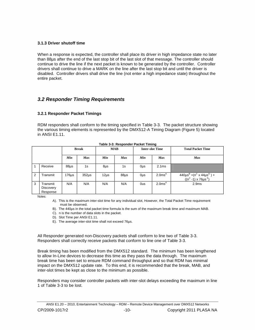
3.1.3 Driver shutoff time
When a response is expected, the controller shall place its driver in high impedance state no later than 88µs after the end of the last stop bit of the last slot of that message. The controller should continue to drive the line if the next packet is known to be generated by the controller. Controller drivers shall continue to drive a MARK on the line after the last stop bit and until the driver is disabled. Controller drivers shall drive the line (not enter a high impedance state) throughout the entire packet.
3.2.1 Responder Packet Timings
RDM responders shall conform to the timing specified in Table 3-3. The packet structure showing the various timing elements is represented by the DMX512-A Timing Diagram (Figure 5) located in ANSI E1.11.
Table 3-3: Responder Packet Timing
Break MAB Inter-slot Time Total Packet Time
Min Max Min Max Min Max Max
1 Receive 88µs 1s 8µs 1s 0µs 2.1ms
2 Transmit 176µs 352µs 12µs 88µs 0µs 2.0msA 440µs
B +(n
C x 44µs
D ) +
((nC -1) x 76µs
E)
3 Transmit Discovery
Response
N/A N/A N/A N/A 0us 2.0msA 2.9ms
Notes:
A). This is the maximum inter-slot time for any individual slot, However, the Total Packet Time requirement must be observed.
B). The 440µs in the total packet time formula is the sum of the maximum break time and maximum MAB.
C). n is the number of data slots in the packet.
D). Slot Time per ANSI E1.11.
E). The average inter-slot time shall not exceed 76µs.
All Responder generated non-Discovery packets shall conform to line two of Table 3-3. Responders shall correctly receive packets that conform to line one of Table 3-3.
Break timing has been modified from the DMX512 standard. The minimum has been lengthened to allow In-Line devices to decrease this time as they pass the data through. The maximum break time has been set to ensure RDM command throughput and so that RDM has minimal impact on the DMX512 update rate. To this end, it is recommended that the break, MAB, and inter-slot times be kept as close to the minimum as possible.
Responders may consider controller packets with inter-slot delays exceeding the maximum in line 1 of Table 3-3 to be lost.
3.2 Responder Timing Requirements

ANSI E1.20 – 2010, Entertainment Technology – RDM – Remote Device Management over DMX512 Networks
CP/2009-1017r2 -11- Copyright 2011 PLASA NA
3.2.2 Responder Packet spacing
Correct RDM performance requires certain minimum and maximum packet spacing.
The start of a packet (Start of Packet or SOP) is defined as the leading edge of the BREAK.
In the case of break-less responses (DISC_UNIQUE_BRANCH), the SOP is defined as the leading edge of the start bit of the first slot sent by the Responder.
The end of packet (End of Packet or EOP) is defined as the trailing edge of the second stop bit of the last slot transmitted. The "trailing edge" is defined as 44µs following the leading edge of the start bit. Note that there is no physical transition at the "trailing edge" of the stop bit as the line must be left in a Marking state.
All times are shown in Table 3-4 are from the Controller‘s EOP to the Responder‘s SOP at the responder.
RDM responders shall conform to the timings specified in Table 3-4.
Table 3-4: Responder Packet Spacing Times
Line Description Min1 Max
1 Controller: Request2 -> Responder: Response 176µs 2ms
2 Controller: Discovery -> Responder: Response 176µs 2ms
Table 3-4 Notes:
1.) Minimum time is to allow the data link to turn around.
2.) A Request is any controller message to which a response is expected.
3.2.3 Responder discovery response driver enable time
Responders shall not drive the line in a marking state for more than 12µs prior to the beginning of the first start bit.
3.2.4 Driver shutoff time
All responders shall place their drivers in a high impedance state no later than 88µs after the end of the last stop bit of the last slot of a response. The responder‘s driver shall continue to drive a MARK on the line after the last stop bit and until the driver is disabled. The responder‘s driver shall drive the line (not enter a high impedance state) throughout the entire packet.
3.2.5 Discovery Response MARK time
Responders may wish to drive a MARK on the line for at least 4µs prior to the first start bit of the discovery response. This will ensure that all other devices on the line recognize the start bit.

ANSI E1.20 – 2010, Entertainment Technology – RDM – Remote Device Management over DMX512 Networks
CP/2009-1017r2 -12- Copyright 2011 PLASA NA
A correctly functioning RDM system operates without data collisions, except during Discovery (Section 7). During device discovery there will frequently be data collisions. While many collisions may be detected at the protocol level, some collisions could be interpreted as properly framed packets. While the physical layer does not impose any special requirements for hardware detection of collisions, it is recommended that proper character framing is verified by both controllers and responders.
4 In-Line Devices
DMX512 systems use several types of In-Line devices (such as a splitter or merger) to distribute the data. Since RDM uses bi-directional communication, RDM In-Line devices have additional operational requirements compared to non-RDM In-Line devices. This section describes requirements unique to RDM In-Line devices.
There are two ways in-line devices can operate: Transparent and Proxy. This section pertains to Transparent In-line devices. Proxy devices are described in Section 8.
On In-Line devices, the port receiving data communication from the Controller shall be designated as the Responder Port. The ports generating data communication to the end-devices shall be designated as the Command Port(s). For example, a splitter would typically have a single Responder Port with multiple Command Ports.
4.1.1 Transparent In-Line devices
A Transparent In-line device provides bi-directional transfer of data between the response and command ports. It does not initiate discovery on its command ports.
Transparent In-line devices may make use of the packet data (e.g. Slot Count) to maintain proper timings. Such devices may generate their own packet/slot timing but should have minimal impact on packet spacing. A Transparent In-line device may or may not be discoverable as an RDM device.
Transparent In-Line devices of different types may be cascaded to create the RDM distribution network. Such devices must abide by certain timing restrictions to allow a system to operate within the requirements outlined in Section 3.2 Responder Timing Requirements.
3.3 Data collisions
4.1 Overview
4.2 Transparent In-Line Device Timing Requirements

ANSI E1.20 – 2010, Entertainment Technology – RDM – Remote Device Management over DMX512 Networks
CP/2009-1017r2 -13- Copyright 2011 PLASA NA
4.2.1 Port Turnaround
After receiving an RDM request packet, the in-line device shall switch to receiving data at its Command Ports, within 132µs of the end of the RDM packet.
After receiving an RDM request packet, the first port that is pulled to a low state for the start of a BREAK becomes the active port. Note that this port may be the responder port, in which case the in-line device shall return to forward data flow. Otherwise, data from the active port shall drive the responder port and may drive all other command ports on the in-line device.
After the EOP of a response packet an in-line device shall be capable of receiving data on its responder port (and returning to forward data flow) within 132µs.
4.2.1.1 Port Turnaround during Discovery
Because there may not be a recognizable EOP for the response, the in-line device shall return to forward data flow no sooner than Table 3-2 Line 2 Minimum Time minus 200µs from Table 3-2 Note 3. The in-line device shall be capable of returning to forward data flow no later than Table 3-2 Line 2 Minimum Time.
4.2.2 Data Delay
Transparent In-Line devices shall not delay the data by more than 88µs. This is a maximum delay. Delay times can be shorter, theoretically 0µs. This allows operation with up to four Transparent In-Line devices between the controller and responder. This accounts for the 704µs (352µs send and 352µs receive) of system delay time included in Section 3.1.2 Controller Packet spacing
4.2.3 Bit Distortion
Some In-Line devices distort bit times due, in part, to unsymmetrical propagation delays and transition times (the low to high time differs from the high to low time). Total bit time distortion shall be limited to a maximum of +/- 1.875% (75ns). This delay is not cumulative during a slot.
tL-H
tH-L
Start LSB MSB StopData = 0x55
Figure 4-2: Bit Asymmetrical Delay
Transparent In-Line devices may regenerate the slot timings. If so, they shall conform to the slot timing requirements in Section 3.

ANSI E1.20 – 2010, Entertainment Technology – RDM – Remote Device Management over DMX512 Networks
CP/2009-1017r2 -14- Copyright 2011 PLASA NA
4.2.4 BREAK timing
RDM timing allows up to four cascaded Transparent In-Line devices.
In-line devices shall be permitted to shorten the duration of the BREAK immediately following an RDM request packet. The BREAK shall not be shortened by more than 22µs. This requirement allows for systems with four In-line devices in series, while assuring that breaks are always 88µs or longer. Manufacturers of in-line DMX512 processing or distribution devices shall declare any shortening of the BREAK.
RDM In-Line Devices shall conform to the packet timing requirements of E1.11 when used in a non-RDM system, including the correct reception and retransmission of NSC packets with the minimum 88µs break.
An in-line device may also be a responder. This allows for status monitoring or configuration of the in-line device itself.
4.3 In-Line devices operating as part of Non-RDM system
4.4 In-line Devices as Responders

ANSI E1.20 – 2010, Entertainment Technology – RDM – Remote Device Management over DMX512 Networks
CP/2009-1017r2 -15- Copyright 2011 PLASA NA
5 Device Addressing
Responders and Controllers identify themselves with a 48-bit Unique ID (UID). The Unique ID (UID) consists of a 16-bit ESTA assigned Manufacturer ID with a 32-bit Device ID, as shown in Table 5-1.
Table 5-1: Unique ID (UID) Format
ESTA Manufacturer ID
(16-bit)
Device ID
(32-bit)
The 32-bit device ID shall be unique throughout all products manufactured under a specific Manufacturer ID, to ensure that no two devices with the same UID will appear on the data link.
For use in this standard the value of the 16-bit Manufacturer ID shall be restricted to 0x0001 through 0x7FFF.
A responder that is not acting as a proxy shall only respond to messages addressed to its UID.
A responder that acts a proxy device shall only respond to messages addressed to its own UID, or the UID of one of the represented devices.
In general, each Responder port should be assigned a single Device ID. The Sub-Device mechanism (see Section 9) is provided to support the logical organization of a device's components.
Multiple Command ports on a device that originate messages may use the same Device ID, but shall identify each port uniquely using the Port ID/Response Type field as detailed in Section 6.2.7.
Information on Manufacturer ID Registration can be found in E1.11 Annex E.
The recommended method for representing the UID in text is in hexadecimal format with a colon separating the Manufacturer ID and the Device ID.
An example of such would be: mmmm:dddddddd, where mmmm is the Manufacturer ID in hexadecimal and dddddddd is the Device ID in hexadecimal.
5.1 General
5.2 UID Text Representation

ANSI E1.20 – 2010, Entertainment Technology – RDM – Remote Device Management over DMX512 Networks
CP/2009-1017r2 -16- Copyright 2011 PLASA NA
A message may be addressed to multiple responders by using a special value in the Destination UID field. This technique is commonly used with Discovery Messages and may also be used with any SET_COMMAND message. Messages may be addressed to all devices, or to all devices of a specific manufacturer.
To address a message to all devices regardless of Manufacturer, the BROADCAST_ALL_DEVICES_ID shall be used in the Destination UID field.
To address a message to all devices of a specific Manufacturer, the ALL_DEVICES_ID shall be used with the desired Manufacturer ID in the Destination UID field.
When Broadcast Addressing is used for non-Discovery messages, the responders shall not send a response.
Some devices may have multiple responder ports that are Discoverable (i.e., they respond to DISC_UNIQUE_BRANCH messages). On these devices, each responder port shall identify itself with a unique Device ID.
Furthermore, one responder port shall be designated as the primary port, to which the other responder ports are bound, allowing the responder ports to be associated together as a single physical device. The implementation of Binding Device ID's is discussed in Section 7.6.2.
5.3 Broadcast Message Addressing
5.4 Responders with multiple Responder Ports in a single Device.

ANSI E1.20 – 2010, Entertainment Technology – RDM – Remote Device Management over DMX512 Networks
CP/2009-1017r2 -17- Copyright 2011 PLASA NA
6 Message Structure All RDM packets shall use the following message structure, with the exception of the Discovery Unique Branch response message. The format of the Discovery Unique Branch message is detailed in Section 7.5 Discovery Unique Branch Message.
All multi-byte data shall be transmitted in Big-Endian order.
For example, 0x01AB02CD would be transmitted as shown in Table 6-1.
Table 6-1: Byte Ordering
All fields within the packet shown in Table 6-2 are assumed to be 8-bit values unless otherwise stated.
Table 6-2: Packet Format
START Code
Sub-Start Code
Message Length
Destination UID (48-bit)
Source UID (48-bit)
Transaction Number (TN)
Port ID / Response Type
Message Count
Sub-Device (16-bit)
Message Data Block (MDB)
(Variable Size)
Checksum (16-bit)
6.1 Byte Ordering
Slot # Data
i 0x01 Most Significant Byte
i+1 0xAB
i+2 0x02
i+3 0xCD Least Significant Byte
6.2 Packet Format

ANSI E1.20 – 2010, Entertainment Technology – RDM – Remote Device Management over DMX512 Networks
CP/2009-1017r2 -18- Copyright 2011 PLASA NA
6.2.1 START Code
This field shall contain the defined RDM START Code (SC_RDM). Controllers and Responders shall always send SC_RDM in this slot, and any packet containing a value other than SC_RDM is outside the scope of this standard.
6.2.2 Sub START Code
This field shall contain the Sub-START Code within RDM that defines this packet structure (SC_SUB_MESSAGE). Future versions of this standard which may have additional or different packet structures would use this field to identify the packet structure being used.
Controllers shall always send SC_SUB_MESSAGE in this slot, and Responders shall ignore any packets containing other values.
6.2.3 Message Length
The Message Length value is defined as the number of slots in the RDM Packet including the START Code and excluding the Checksum. Each slot is an 8-bit value.
The Message Length field points to the Checksum High Slot.
Table 6-3 below illustrates the relationship of Message Length to the Checksum using the Get Status Messages command as an example.
Table 6-3: Example of Packet showing Message Length Pointer to Checksum
Slot # Description Data Value Remarks
0 START Code SC_RDM
1 Sub-START Code SC_SUB_MESSAGE
2 Message Length 25 (Slot # of Checksum High) Range 24 to 255.
3 – 8 Destination UID 0x123456789ABC
9 – 14 Source UID 0xCBA987654321
15 Transaction Number (TN) 0
16 Port ID / Response Type 1
17 Message Count 0
18 - 19
Sub-Device 0
20 Command Class (CC) GET_COMMAND
21 – 22
Parameter ID (PID) STATUS_MESSAGES
23 Parameter Data Length (PDL)
1 Range 0 to 231
24 Parameter Data (PD) STATUS_ERROR
25 Checksum High
26 Checksum Low

ANSI E1.20 – 2010, Entertainment Technology – RDM – Remote Device Management over DMX512 Networks
CP/2009-1017r2 -19- Copyright 2011 PLASA NA
6.2.4 Destination UID
The Destination UID is the UID of the target device(s).
6.2.5 Source UID
The Source UID is the UID of the device originating this packet.
6.2.6 Transaction Number (TN)
The Transaction Number is an unsigned 8-bit field. Controller generated packets increment this field every time an RDM packet is transmitted. This field shall be initialized to 0 and roll over from 255 to 0.
Responders shall reply with their Transaction Number set to the Transaction Number contained in the controller packet to which they are responding.
The Transaction Number can be used to help match a response message to the Controller‘s request.
6.2.7 Port ID / Response Type
This field serves different functions depending on whether the message is being generated by the controller or the responder.
6.2.7.1 Port ID / Response Type field for Controller Generated Messages
For Controller generated messages (GET_COMMAND, SET_COMMAND, and
DISCOVERY_COMMAND), the Port ID field shall be set in the range of 1-255 identifying the Controller Port being used, such that the combination of Source UID and Port ID will uniquely identify the controller and port where the message originated.
6.2.7.2 Port ID / Response Type field for Responder Generated Messages
For Responder generated messages (GET_COMMAND_RESPONSE, SET_COMMAND_RESPONSE, and DISCOVERY_COMMAND_RESPONSE), this field is used as the Response Type field. Response Type Field usage is detailed in Section 6.3.

ANSI E1.20 – 2010, Entertainment Technology – RDM – Remote Device Management over DMX512 Networks
CP/2009-1017r2 -20- Copyright 2011 PLASA NA
6.2.8 Message Count
The message count field is used by a responder to indicate that additional data is now available for collection by a controller. This data (which might be unrelated to the current message transaction) should be collected by the controller using the GET:QUEUED_MESSAGE command.
6.2.8.1 Message Count field for Controller Generated Messages
The Message Count shall be set to 0x00 in all controller generated requests.
6.2.8.2 Message Count field for Responder Generated Messages
The Message Count shall be incremented by a responder whenever there is a new message pending collection by a controller. Thus a controller can determine, from any response, the number of queued messages pending.
When replying to a GET: QUEUED_MESSAGE command, a responder shall decrement the Message Count prior to responding, unless it is already zero.
If a responder has more than 255 messages queued, then the Message Count field shall remain at 255 until the number of queued messages is reduced below that number.
The following sequence of messages illustrates the use of the Message Count field.
Controller sends GET: LANGUAGE
(Port ID)
0x01 - 0xFF
(Message Count)
0x00
(Sub-Device)
0x0000
(CC)
GET_COMMAND
(PID)
LANGUAGE
(PDL)
0x00
(PD)
Not Present
Responder replies with ACK and the current language. Message Count shows 0x02 indicating that two other responses are ready for retrieval.
(Response Type)
ACK
(Message Count)
0x02
(Sub-Device)
0x0000
(CC)
GET_COMMAND_RESPONSE
(PID)
LANGUAGE
(PDL)
0x02
(PD)
2 character alpha code for ISO 639-1

ANSI E1.20 – 2010, Entertainment Technology – RDM – Remote Device Management over DMX512 Networks
CP/2009-1017r2 -21- Copyright 2011 PLASA NA
Controller sends GET: QUEUED_MESSAGE:
(Port ID)
0x01 - 0xFF
(Message Count)
0x00
(Sub-Device)
0x0000
(CC)
GET_COMMAND
(PID)
QUEUED_MESSAGE
(PDL)
0x01
(PD)
STATUS_ERROR
Responder sends queued message with Message Count decremented showing only 1 pending messages remains.
(Response Type)
ACK
(Message Count)
0x01
(Sub-Device)
0x0000
(CC)
GET_COMMAND_
RESPONSE
(PID)
DMX_START_ADDRESS
(PDL)
0x02
(PD)
DMX512 Address (16-bit)
Controller sends another GET: QUEUED_MESSAGE:
(Port ID)
0x01 - 0xFF
(Message Count)
0x00
(Sub-Device)
0x0000
(CC)
GET_COMMAND
(PID)
QUEUED_MESSAGE
(PDL)
0x01
(PD)
STATUS_ERROR
Responder sends queued message with Message Count decremented (and now zero) showing no further pending messages exist.
(Response Type)
ACK
(Message Count)
0x00
(Sub-Device)
0x0000
(CC)
GET_COMMAND_
RESPONSE
(PID)
DMX_PERSONALITY
(PDL)
0x02
(PD)
Current Personality # of Personalities

ANSI E1.20 – 2010, Entertainment Technology – RDM – Remote Device Management over DMX512 Networks
CP/2009-1017r2 -22- Copyright 2011 PLASA NA
6.2.9 Sub-Device Field
Sub-devices should be used in devices containing a repetitive number of similar modules, such as a dimmer rack. The Sub-Device field allows Parameter messages to be addressed to a specific module within the device to set or get properties of that module.
The 16-bit sub-device field provides a range of 512 valid sub-devices, addressed from 1 - 512. The value of 0xFFFF is reserved as a SUB_DEVICE_ALL_CALL. A value of 0x0000 shall be used to address the root or base properties of the device that do not belong to any sub-device module.
The Parameter ID designates which parameter on the sub-device is being addressed.
The use of Sub-Devices is described further in Section 9.
6.2.10 Message Data Block (MDB)
Table 6-4 shows the format of the Message Data Block portion of the data packet from Table 6-2.
Table 6-4: Message Data Block (MDB) Format
Command Class (CC)
Parameter ID (PID)
[16-bit]
Parameter Data Length (PDL)
Parameter Data (PD)
[Variable Length]
6.2.10.1 Command Class (CC)
The Command Class (CC) in Table 6-5 specifies the action of the message.
Table 6-5: Command Class Description
Command Class Response Expected
Description
GET_COMMAND YES Request the value or status of a parameter from the device.
GET_COMMAND_RESPONSE Response from a GET_COMMAND message.
SET_COMMAND YES Change the value of a parameter within the device.
SET_COMMAND_RESPONSE Response from a SET_COMMAND message.
DISCOVERY_COMMAND YES Message related to the Discovery Process.
DISCOVERY_COMMAND
_RESPONSE
Response from a DISCOVERY_COMMAND
Message.
Responders shall always generate a response to GET_COMMAND and SET_COMMAND messages except when the Destination UID of the message is a broadcast address. Responders shall not respond to commands sent using Broadcast addressing, in order to prevent collisions.
Command Class values are enumerated in Table A-1.

ANSI E1.20 – 2010, Entertainment Technology – RDM – Remote Device Management over DMX512 Networks
CP/2009-1017r2 -23- Copyright 2011 PLASA NA
6.2.10.2 Parameter ID (PID)
The Parameter ID is a 16-bit number that identifies a specific type of Parameter Data.
The Parameter ID (PID) may represent either a well known Parameter such as those defined in this document, or a Manufacturer-specific parameter whose details are either published by the Manufacturer for
third-party support or proprietary for the Manufacturer‘s own use.
ESTA defined PID‘s shall be in the range of 0x0000 – 0x7FDF and are enumerated in Table A-3. PID‘s in the range of 0x7FE0 – 0x7FFF are reserved for future uses of this standard. PID’s in Table A-3 are organized into categories to create logical groupings.
Manufacturer-specific PID‘s shall be created in the range of 0x8000 – 0xFFDF. Uniqueness of PID‘s in this range is accomplished by associating the PID with the Manufacturer ID found as the most significant 16-bits of the UID. PID‘s in the range of 0xFFE0 – 0xFFFF are reserved for future uses of this standard.
Manufacturer-Specific PID values should be selected by choosing the appropriate category from Table A-3 and adding an offset of 0x8000 to preserve a logical organization.
A manufacturer shall not use the same manufacturer-specific PID value for more than one meaning within any products falling under a given Manufacturer ID.
Controllers shall not send Manufacturer-specific PID messages addressed to the all manufacturer BROADCAST_ALL_DEVICES_ID. Responders shall ignore any manufacturer-specific message addressed to the BROADCAST_ALL_DEVICES_ID.
6.2.10.2.1 Minimum Required Parameter Support
All devices shall support the minimum set of PID‘s indicated by the ―Required‖ column of Table A-3.
6.2.10.3 Parameter Data Length (PDL)
The Parameter Data Length (PDL) is the number of slots included in the Parameter Data area that it precedes. When this field is set to 0x00 it indicates that there is no Parameter Data following.
6.2.10.4 Parameter Data (PD)
The Parameter Data is of variable length. The content format is PID dependent.

ANSI E1.20 – 2010, Entertainment Technology – RDM – Remote Device Management over DMX512 Networks
CP/2009-1017r2 -24- Copyright 2011 PLASA NA
6.2.11 Checksum
The Checksum field is the unsigned, modulo 0x10000, 16-bit additive checksum of the entire packet‘s slot data, including START Code. The checksum is an additive sum of the 8-bit fields into a 16-bit response value.
If the checksum field in the packet does not match the calculated checksum, then the packet shall be discarded and no response sent.
Table 6-6 shows an example of how the checksum is calculated. In the example below, the Checksum is the sum of all the slots from Slot 0 to Slot 24.
Table 6-6: Checksum Usage Example
Slot # Description Data Value Remarks
0 START Code 0xCC SC_RDM
1 Sub START Code 0x01 SC_SUB_MESSAGE
2 Message Length 0x19 Slot # of Checksum High = 25
3
Destination UID
0x12
0x123456789abc
4 0x34
5 0x56
6 0x78
7 0x9A
8 0xBC
9
Source UID
0xCB
0xcba987654321
10 0xA9
11 0x87
12 0x65
13 0x43
14 0x21
15 Transaction Number 0x00
16 Port ID / Response Type
0x01
17 Message Count 0x00
18 Sub-Device
0x00 Root Device
19 0x00
20 Command Class 0x20 GET_COMMAND
21 Parameter ID
0x00 STATUS_MESSAGES
22 0x30
23 Parameter Data Length
0x01
24 Parameter Data 0x04 STATUS_ERROR
25 Checksum High 0x06 0x066A
26 Checksum Low 0x6A

ANSI E1.20 – 2010, Entertainment Technology – RDM – Remote Device Management over DMX512 Networks
CP/2009-1017r2 -25- Copyright 2011 PLASA NA
The Response Type field is used in messages from Responders to indicate the acknowledgement type of the response.
Response Type values are enumerated in Table A-2. Table 6-7 below indicates the valid codes for the Response Type field entry. This table does not indicate whether a response occurs, only the allowed values of the Response Type field if a response occurs.
Table 6-7: Response Type Field Allowable Values from Responder
Command Class ACK ACK_
OVERFLOW
ACK_
TIMER
NACK_ REASON
DISCOVERY_
COMMAND_ RESPONSE
X X X
GET_COMMAND_ RESPONSE
SET_COMMAND_ RESPONSE
Table 6-8: Key for Table 6-7
Icon Notes
Response Type Allowed
X Response Type Not Allowed
6.3.1 Acknowledge (RESPONSE_TYPE_ACK)
The response RESPONSE_TYPE_ACK indicates that the responder has correctly received the controller message and is acting upon the message.
The format of the MDB of the message is defined in the corresponding message definition.
6.3.2 Acknowledge Overflow (RESPONSE_TYPE_ACK_OVERFLOW)
The response RESPONSE_TYPE_ACK_OVERFLOW indicates that the responder has correctly received the controller message and is acting upon the message, but there is more response data available than will fit in a single response message.
This message shall be used in cases such as GET: PROXIED_DEVICES and GET: SUPPORTED PARAMETERS where the response data is larger than can fit in a single response message.
6.3 Response Type Field Values

ANSI E1.20 – 2010, Entertainment Technology – RDM – Remote Device Management over DMX512 Networks
CP/2009-1017r2 -26- Copyright 2011 PLASA NA
To receive the remaining data, the controller should continue to send GET_COMMANDS for the same PID. The responder shall send subsequent blocks of data with a response type of RESPONSE_TYPE_ACK_OVERFLOW until the remaining data can fit in a single message. The responder shall set the response type to RESPONSE_TYPE_ACK on the final response message in the sequence, to indicate completion of the data transfer. The responder shall not queue up subsequent messages when a GET_COMMAND results in a response type of RESPONSE_TYPE_ACK_OVERFLOW. This allows the controller to explicitly manage the transfer of larger data blocks. The responder shall abort a partial transfer of overflow data for a PID when receiving a command for a different PID before the overflow data transfer is complete. A subsequent command for the overflow PID will result in a new data transfer starting at the beginning of the data set.
The format of the MDB of the message is defined in the corresponding message definition.
An example of this Response Type is listed below:
Controller sends GET: PROXIED_DEVICES
(Port ID)
0x01
(Message Count)
0x00
(Sub-Device)
0x0000
(CC)
GET_COMMAND
(PID)
PROXIED_DEVICES
(PDL)
0x00
(PD)
Not Present
Responder sends response message indicating overflow condition, that more data is available.
(Response Type)
ACK_OVERFLOW
(Message Count)
0x00-0xFF
(Sub-Device)
0x0000
(CC)
GET_COMMAND_
RESPONSE
(PID)
PROXIED_DEVICES
(PDL)
0xE4
(PD)
Packed Field with 38 UID‘s (48-bits each). Maximum number of UID‘s that can be fit within PDL limit.
Controller sends another GET: PROXIED_DEVICES
(Port ID)
0x01
(Message Count)
0x00
(Sub-Device)
0x0000
(CC)
GET_COMMAND
(PID)
PROXIED_DEVICES
(PDL)
0x00
(PD)
Not Present

ANSI E1.20 – 2010, Entertainment Technology – RDM – Remote Device Management over DMX512 Networks
CP/2009-1017r2 -27- Copyright 2011 PLASA NA
Responder sends final response message in sequence:
(Response Type)
ACK
(Message Count)
0x00-0xFF
(Sub-Device)
0x0000
(CC)
GET_COMMAND_
RESPONSE
(PID)
PROXIED_DEVICES
(PDL)
0x1E
(PD)
Packed Field with 5 UID‘s (48-bits each).
6.3.3 Acknowledge Timer (RESPONSE_TYPE_ACK_TIMER)
RESPONSE_TYPE_ACK_TIMER indicates that the responder is unable to supply the requested GET information or SET confirmation within the required response time.
The format of the MDB of the response message is defined as follows:
Response:
(Response Type)
ACK_TIMER
(Message Count)
OldMC
(Sub-Device)
Copy of Controller SD
(CC)
GET_COMMAND_RESPONSE
(PID)
Copy of Controller PID
(PDL)
0x02
(PD)
Estimated Response Time (16-bit)
The Estimated Response Time is a 16-bit unsigned field that defines the estimated time in tenths of a second (100ms increments) that will elapse before the responder can provide the required information.
When the responder is able to provide the required information, it shall add the correctly formatted GET_COMMAND_RESPONSE message or SET_COMMAND_RESPONSE message to its QUEUED_MESSAGE list. It shall also increment its Message Count at the time the message is added to the QUEUED_MESSAGE list.
This mechanism allows the controller to retrieve deferred Get command data by issuing GET: QUEUED_MESSAGE.
The following transaction provides an example of this mechanism:

ANSI E1.20 – 2010, Entertainment Technology – RDM – Remote Device Management over DMX512 Networks
CP/2009-1017r2 -28- Copyright 2011 PLASA NA
Controller sends GET: LAMP_STRIKES
(Port ID)
0x01
(Message Count)
0x00
(Sub-Device)
0x0000
(CC)
GET_COMMAND
(PID)
LAMP_STRIKES
(PDL)
0x00
(PD)
Not Present
Responder is unable to retrieve data and replies with ACK_TIMER indicating it will need approximately 60 seconds to process the request:
(Response Type)
ACK_TIMER
(Message Count)
0x00
(Sub-Device)
0x0000
(CC)
GET_COMMAND_RESPONSE
(PID)
LAMP_STRIKES
(PDL)
0x02
(PD)
0x0258
Responder data becomes available for response and has been added to the QUEUED_MESSAGE list. Any intervening messages would show an incremented message count.
80 seconds later
Controller sends GET: QUEUED_MESSAGE:
(Port ID)
0x01
(Message Count)
0x00
(Sub-Device)
0x0000
(CC)
GET_COMMAND
(PID)
QUEUED_MESSAGE
(PDL)
0x01
(PD)
STATUS_ERROR
Responder sends queued message:
(Response Type)
ACK
(Message Count)
0x00
(Sub-Device)
0x0000
(CC)
GET_COMMAND_
RESPONSE
(PID)
LAMP_STRIKES
(PDL)
0x04
(PD)
Lamp Strikes (32-bit)

ANSI E1.20 – 2010, Entertainment Technology – RDM – Remote Device Management over DMX512 Networks
CP/2009-1017r2 -29- Copyright 2011 PLASA NA
6.3.4 Negative Acknowledge (RESPONSE_TYPE_NACK_REASON)
The response RESPONSE_TYPE_NACK_REASON shall only be used in conjunction with the Command Classes GET_COMMAND_RESPONSE & SET_COMMAND_RESPONSE.
RESPONSE_TYPE_NACK_REASON indicates that the responder is unable to reply with the requested GET information or unable to process the specified SET command.
The format of the MDB of the response message is defined as follows:
Response:
(Response Type)
NACK_REASON
(Message Count)
0x00-0xFF
(Sub-Device)
Copy of Controller SD
(CC)
GET_COMMAND_RESPONSE
(PID)
Copy of Controller PID
(PDL)
0x02
(PD)
NACK Reason Code (16-bit)
The NACK Reason code defines the reason that the responder is unable to comply with the request.
Valid NACK Reason Codes are enumerated in Table A-17.

ANSI E1.20 – 2010, Entertainment Technology – RDM – Remote Device Management over DMX512 Networks
CP/2009-1017r2 -30- Copyright 2011 PLASA NA
7 Discovery Method
Responders may be discovered by conducting a binary search based on the 48-bit UID.
Collisions are expected as part of the discovery process. Once all responders have been discovered, the system operates in a collision-free environment by utilizing the UID‘s for addressing messages. While search methods other than a binary search are allowed, this is the preferred method and is described in this section.
Figure 7-1 illustrates a Binary Search Tree. Each node of the tree represents a decision fork for the search, and is labeled with a value pair representing the corresponding starting and ending UID values for that branch of the search.
The controller discovers each device by working through the tree from right to left exploring each branch that provides a response.
Figure 7-1: Binary Search
7.1 General
7.2 Binary Search Tree
0,(2 48 -1)
0,(2 47 - 1)
0,(2 46 - 1)
0,(2 45 - 1)
(2 46 ),(2 47 - 1)
0,0 1,1 2,2 3,3
(2 47
),(2 48
- 1)
(2 45 ),(2 46 - 1)
(2 48
- 1),(2 48
- 1) (2 48
48 - 2) - 2),(2

ANSI E1.20 – 2010, Entertainment Technology – RDM – Remote Device Management over DMX512 Networks
CP/2009-1017r2 -31- Copyright 2011 PLASA NA
Devices respond to discovery messages (DISC_UNIQUE_BRANCH) unless they have been muted for discovery. The normal discovery process consists of un-muting all devices, and as they are individually discovered, muting each device. The devices must be muted as they are discovered so that they will not respond and create response collisions as the controller attempts to discover other devices. In general, the discovery process proceeds as follows:
1. For full Discovery, clear all Discovery Mute flags by sending the DISC_UN_MUTE message with the Destination UID set to BROADCAST_ALL_DEVICES_ID.
2. Send a DISC_UNIQUE_BRANCH message with parameter data corresponding to the current branch of the binary search tree. Any device with a UID greater than or equal to the Lower Bound and less than or equal to the Upper Bound that was transmitted in the Parameter Data area will provide a response message.
3. Numerous collisions are expected. Any response indicates devices within that UID range. No response indicates there are no devices within that branch.
4. If the checksum is valid for the response, attempt to Mute the device at the UID included in the response by sending the DISC_MUTE message. If a device is located at that UID then it will provide a response message and will no longer respond to any DISC_UNIQUE_BRANCH messages. Test the same branch again for any further responses. If the checksum is invalid then continue branching down the tree, as multiple devices likely exist.
5. When searching the lowest branch (when both sides of the ordered pair are equal) of the tree, send the DISC_MUTE message to that UID. If a device is located at that UID then it will provide a response message and will no longer respond to any DISC_UNIQUE_BRANCH messages.
6. After muting the device, continue searching the unchecked branches by repeating the process.
Each responder shall maintain a Discovery Mute Flag for each responder port. When set, it indicates that a responder will not respond to Discovery Unique Branch messages directed to the UID of that port.
7.4.1 Clearing of Mute Flag
The Mute Flag shall be cleared upon any of the following conditions:
Power on, hardware reset, or software reset of responder.
Reset command message (RESET_DEVICE) sent to responder.
Receipt of DISC_UN_MUTE message addressed to the responder either by using the device‘s specific UID or through Broadcast Addressing.
7.3 Discovery Process Steps
7.4 Discovery Mute Flag

ANSI E1.20 – 2010, Entertainment Technology – RDM – Remote Device Management over DMX512 Networks
CP/2009-1017r2 -32- Copyright 2011 PLASA NA
The following message and response are used for the device discovery process. Discovery messages shall always be addressed to Root Devices (Sub-Device = 0).
A responder shall only respond to this message if its UID is greater than or equal to the Lower Bound UID and less than or equal to the Upper Bound UID included in the message‘s parameter data, and if it has not been muted through the DISC_MUTE message.
The DISC_UNIQUE_BRANCH message shall always be sent to the ALL_DEVICES_ID UID Address, since all devices must process this message.
Controller: (Port ID)
0x01 - 0xFF
(Message Count)
0x00
(Sub-Device)
0x0000
(CC)
DISCOVERY_COMMAND
(PID)
DISC_UNIQUE_BRANCH
(PDL)
0x0C
(PD)
Lower Bound UID
(48-bit)
Upper Bound UID
(48-bit)
Response:
The response message has a number of exceptions to the normal Packet structure to minimize the effect of collisions on legacy devices from appearing as a BREAK, NULL START Code, and data. The format of the DISC_UNIQUE_BRANCH Response Packet is described in Table 7-1.
Controllers shall treat any line activity during the response window as a reply and branch further if necessary, or attempt to Mute a device if an error-free response is received.
The Response to the DISC_UNIQUE_BRANCH message shall not contain a BREAK in the packet. The Responding Device shall reply by enabling the transmitter and simply transmitting the response packet.
No other message structure or normal header information shall be transmitted in the response. To any device monitoring the line, the response will be interpreted as a continuation of the original packet sent from the controller.
All timing information regarding Discovery Responses is included in Section 3.2 Responder Timing Requirements.
7.5 Discovery Unique Branch Message (DISC_UNIQUE_BRANCH)

ANSI E1.20 – 2010, Entertainment Technology – RDM – Remote Device Management over DMX512 Networks
CP/2009-1017r2 -33- Copyright 2011 PLASA NA
Response Packet from Device for DISC_UNIQUE_BRANCH message:
Table 7-1: DISC_UNIQUE_BRANCH Response Packet Encoding
Response Packet Slot
Slot Data Comments
1 0xFE Response Preamble bytes that may be dropped by an in-line device during turn-around. Not more than one byte may be dropped by each in-line device.
2 0xFE
3 0xFE
4 0xFE
5 0xFE
6 0xFE
7 0xFE
8 0xAA Preamble separator byte
9 (EUID11) Manufacturer ID1 (MSB) OR with 0xAA
Encoded UID (EUID). Encoding by bit-wise OR with 0xAA and 0x55 as shown.
10 (EUID10) Manufacturer ID1 (MSB) OR with 0x55
11 (EUID9) Manufacturer ID0 (LSB) OR with 0xAA
12 (EUID8) Manufacturer ID0 (LSB) OR with 0x55
13 (EUID7) Device ID3 (MSB) OR with 0xAA
14 (EUID6) Device ID3 (MSB) OR with 0x55
15 (EUID5) Device ID2 OR with 0xAA
16 (EUID4) Device ID2 OR with 0x55
17 (EUID3) Device ID1 OR with 0xAA
18 (EUID2) Device ID1 OR with 0x55
19 (EUID1) Device ID0 (LSB) OR with 0xAA
20 (EUID0) Device ID0 (LSB) OR with 0x55
21 (ECS3) Checksum1 (MSB) OR with 0xAA Checksum is the sum of the previous 12 EUID slots. The checksum is an unsigned additive sum of the 8-bit fields into a 16-bit response value.
22 (ECS2) Checksum1 (MSB) OR with 0x55
23 (ECS1) Checksum0 (LSB) OR with 0xAA
24 (ECS0) Checksum0 (LSB) OR with 0x55
The Encoded Unique ID (EUID) is a 12 byte number generated by encoding the UID. It is used solely for devices responding to the Unique Branch Discovery (DISC_UNIQUE_BRANCH) message.
Each byte of the UID shall be encoded into two bytes in the EUID. The purpose of this process is to prevent any combination of colliding EUID data from superimposing in such a way as to generate a properly framed Break – START Code sequence followed by data that some devices might interpret as NULL START Code Data. The response message contains the EUID as outlined in Table 7-1.
Seven extra slots of preamble have been added to the start of the response packet to allow for in-line devices that must shorten the packet for turning around transceivers. If the in-line device shortens the response packet, it shall shorten by exactly one slot time. The controller shall be able to process response packets with 0-7 bytes of preamble.

ANSI E1.20 – 2010, Entertainment Technology – RDM – Remote Device Management over DMX512 Networks
CP/2009-1017r2 -34- Copyright 2011 PLASA NA
7.5.1 Response Unique Branch Message Decoding by Controller
To verify integrity of the response, the UID and checksum should be recovered as shown. A valid response shall require the recovered checksum to match that of the EUID.
Table 7-2: DISC_UNIQUE_BRANCH Response Packet Decoding
Decoded Data Received Encoded Data Comments
Manufacturer ID (MSB) EUID11 & EUID10
UID and Checksum are recovered by bit-wise AND (&) as shown.
Manufacturer ID (LSB) EUID9 & EUID8
UID3 (MSB) EUID7 & EUID6
UID2 EUID5 & EUID4
UID1 EUID3 & EUID2
UID0 (LSB) EUID1 & EUID0
Checksum (MSB) ECS3 & ECS2
Checksum (LSB) ECS1 & ECS0
7.5.2 Collisions
Responses to this message may result in collisions. Controllers shall treat detected line activity as a response, indicating the existence of one or more devices on the line within the specified UID range.
The parameter data area included in the responses to Mute and Un-Mute messages includes a Control Field to inform the controller about specific properties of the device, and may include an optional Binding UID field to indicate the physical arrangement of the responding device.
7.6.1 Control Field
The 16-bit Control Field contains bit flags as in Table 7-3:
Table 7-3: Control Field
Managed Proxy Flag (Bit 0)
The Managed Proxy Flag (Bit 0) shall be set to 1 when the responder is a Proxy device. See Section 8 for information on Proxy Devices.
7.6 Discovery Mute/Un-Mute Messages
Bits 15-4
Reserved (Always set to 0)
Bit 3
Proxied Device Flag
Bit 2
Boot-Loader Flag
Bit 1
Sub-Device Flag
Bit 0
Managed Proxy Flag

ANSI E1.20 – 2010, Entertainment Technology – RDM – Remote Device Management over DMX512 Networks
CP/2009-1017r2 -35- Copyright 2011 PLASA NA
Sub-Device Flag (Bit 1)
The Sub-Device Flag (Bit 1) shall be set to 1 when the responder supports Sub-Devices. See Section 9 for information on Sub-Devices.
Boot-Loader Flag (Bit 2)
The Boot-Loader Flag (Bit 2) shall only be set to 1 when the device is incapable of normal operation until receiving a firmware upload.
It is expected that when in this Boot-Loader mode the device will be capable of very limited RDM communication. The process of uploading firmware is beyond the scope of this document.
Proxied Device Flag (Bit 3) The Proxied Device Flag (Bit 3) shall only be set to 1 when a Proxy is responding to Discovery on behalf of another device. This flag indicates that the response has come from a Proxy, rather than the actual device.
Reserved bits (Bits 4-15)
The Reserved bits (Bits 4-15) are reserved for future implementation and shall be set to 0.
7.6.2 Binding UID
The Binding UID field shall only be included when the responding device contains multiple responder ports. If the device does contain multiple ports, then the Binding UID field shall contain the UID for the primary port on the device.
This Binding UID field allows the controller to associate multiple responder ports discovered within a single physical device.
7.6.3 Discovery Mute Message (DISC_MUTE)
A responder port shall set its Mute flag when it receives this message containing its UID, or a broadcast address.
Controller: (Port ID)
0x01 - 0xFF
(Message Count)
0x00
(Sub-Device)
0x0000
(CC)
DISCOVERY_COMMAND
(PID)
DISC_MUTE
(PDL)
0x00
(PD)
Not Present

ANSI E1.20 – 2010, Entertainment Technology – RDM – Remote Device Management over DMX512 Networks
CP/2009-1017r2 -36- Copyright 2011 PLASA NA
Response:
(Response Type)
ACK
(Message Count)
0x00-0xFF
(Sub-Device)
0x0000
(CC)
DISCOVERY _COMMAND_RESPONSE
(PID)
DISC_MUTE
(PDL)
0x02 or 0x08
(PD)
Control Field
(16-bit)
Binding UID (Optional)
(48-bit)
7.6.4 Discovery Un-Mute Message (DISC_UN_MUTE)
A responder port shall clear its Mute flag when it receives this message containing its UID, or a broadcast address.
Controller:
(Port ID)
0x01 - 0xFF
(Message Count)
0x00
(Sub-Device)
0x0000 (Root)
(CC)
DISCOVERY_COMMAND
(PID)
DISC_UN_MUTE
(PDL)
0x00
(PD)
Not Present
Response:
(Response Type)
ACK
(Message Count)
0x00-0xFF
(Sub-Device)
0x0000
(CC)
DISCOVERY _COMMAND_RESPONSE
(PID)
DISC_UN_MUTE
(PDL)
0x02 or 0x08
(PD)
Control Field
(16-bit)
Binding UID (Optional)
(48-bit)

ANSI E1.20 – 2010, Entertainment Technology – RDM – Remote Device Management over DMX512 Networks
CP/2009-1017r2 -37- Copyright 2011 PLASA NA
The discovery of devices will usually be accomplished using a binary-tree search algorithm. However, modifications of this method can be used and may be more appropriate in certain cases. The flowchart in Figure 7-2 illustrates the recursive portion of the binary search algorithm used to find undiscovered devices within a given UID range. Pseudo-code for this process is located in Appendix E.
Device discovery does not mandate discovery of all connected devices before sending other RDM commands to a discovered device.
A device need not be discovered and muted before accepting and properly acting on NSC packets or other RDM packets. That is, Discovery is not a mandatory requirement for proper device operation.
7.7 Discovery Algorithm

ANSI E1.20 – 2010, Entertainment Technology – RDM – Remote Device Management over DMX512 Networks
CP/2009-1017r2 -38- Copyright 2011 PLASA NA
Figure 7-2: Device Discovery Process

ANSI E1.20 – 2010, Entertainment Technology – RDM – Remote Device Management over DMX512 Networks
CP/2009-1017r2 -39- Copyright 2011 PLASA NA
The controller can detect any new devices that are added to the network by leaving discovered devices muted and sending a DISC_UNIQUE_BRANCH message covering the entire UID range. Only new devices (devices that are not muted) will respond.
Controllers may wish to periodically un-mute all devices then send individual mute commands to the devices it believes are connected. Following this with a DISC_UNIQUE_BRANCH message covering the entire UID range will detect devices that have been added. This technique will discover devices that were muted (for whatever reason) but that the controller did not know were connected.
7.8 Ongoing Device Discovery

ANSI E1.20 – 2010, Entertainment Technology – RDM – Remote Device Management over DMX512 Networks
CP/2009-1017r2 -40- Copyright 2011 PLASA NA
8 Proxy Devices
A proxy is any in-line device that acts as an agent or representative for one or more devices. Represented devices may be non-RDM devices and may be logical (non-physical) devices.
A proxy shall respond to all controller messages on behalf of the devices it represents, as if it is the represented device.
A proxy itself may be discoverable as an RDM device, and may optionally support the Proxy Management commands which may be used by a controller to reduce the complexity of Discovery in a large system. A proxy with such capabilities is known as a managed proxy.
All devices represented by a Proxy are discovered using the standard methods of Discovery described in Section 7.
8.2.1 Represented Devices
A proxy shall respond to all DISC_UNIQUE_BRANCH messages on behalf of each represented device as if it were the represented device. Each represented device should appear to the controller to be an independent RDM device.
A proxy shall provide no more than one response for a DISC_UNIQUE_BRANCH message. A proxy device shall set the Proxied Device Flag to 1 when it is responding to the DISC_MUTE message on behalf of any represented device. This indicates that the response originates from the proxy rather than the actual device. The Managed Proxy Flag shall be cleared, as the response does not relate to the Proxy's own UID.
8.2.2 Proxy Management
A proxy device may itself be discoverable. If it is discoverable, then it shall set the Managed Proxy Flag to 1 when responding to its DISC_MUTE message. This indicates that the device is a Managed Proxy and may support the minimum set of Proxy Management commands.
A Managed Proxy device may support the PROXIED_DEVICES parameter in order to provide the controller with a list of UIDs for represented devices. A controller may choose to speed the discovery process by attempting to directly mute the undiscovered represented devices in the list.
A proxy may use the RESPONSE_TYPE_ACK_TIMER mechanism (See Section 6.3.3) when the controller requests information that is not immediately available from a represented device.
8.1 General
8.2 Discovery
8.3 Response Messages

ANSI E1.20 – 2010, Entertainment Technology – RDM – Remote Device Management over DMX512 Networks
CP/2009-1017r2 -41- Copyright 2011 PLASA NA
Proxy Devices that have exhausted their buffer capacity to hold Queued Message responses as a result of previous GET_COMMAND requests that were responded with ACK_TIMER may send a NACK Reason of NR_PROXY_BUFFER_FULL to alert the Controller to handle pending Queued Messages in the Proxy before requesting further information from other devices handled by the Proxy.
For discoverable proxies, the Proxy Management messages shall always be addressed to the Root Device of the Proxy.
8.4.1 Get Proxied Device Count (PROXIED_DEVICE_COUNT)
This parameter is used to identify the number of devices being represented by a proxy and whether the list of represented device UIDs has changed. If the List Change flag is set then the controller should GET: PROXIED_DEVICES.
The device shall automatically clear the List Change flag after all the proxied UID‘s have been retrieved using the GET: PROXIED_DEVICES message.
A proxy device shall indicate any change in it's device list through a QUEUED_MESSAGE for the PROXIED_DEVICE_COUNT PID. The controller may then get the current list of proxied devices by sending a GET_COMMAND for the PROXIED_DEVICES PID.
Controller: (GET)
(Port ID)
0x01 - 0xFF
(Message Count)
0x00
(Sub-Device)
0x0000 (Root)
(CC)
GET_COMMAND
(PID)
PROXIED_DEVICE_COUNT
(PDL)
0x00
(PD)
Not Present
Response:
(Response Type)
ACK
(Message Count)
0x00-0xFF
(Sub-Device)
0x0000
(CC)
GET_COMMAND_
RESPONSE
(PID)
PROXIED_DEVICE_COUNT
(PDL)
0x03
(PD)
Device Count (16-bit)
List Change (0/1)
8.4 Proxy Management Messages

ANSI E1.20 – 2010, Entertainment Technology – RDM – Remote Device Management over DMX512 Networks
CP/2009-1017r2 -42- Copyright 2011 PLASA NA
8.4.2 Get Proxied Devices (PROXIED_DEVICES)
This parameter is used to retrieve the UIDs from a device identified as a proxy during discovery. The response to this parameter contains a packed list of 48-bit UIDs for all devices represented by the proxy.
If there are no current devices being proxied then the Parameter Data Length field shall be returned as 0x00.
Controller:
(Port ID)
0x01 - 0xFF
(Message Count)
0x00
(Sub-Device)
0x0000 (Root)
(CC)
GET_COMMAND (PID)
PROXIED_DEVICES
(PDL)
0x00
(PD)
Not Present
Response:
(Response Type)
ACK / ACK_OVERFLOW
(Message Count)
0x00-0xFF
(Sub-Device)
0x0000
(CC)
GET_COMMAND_
RESPONSE
(PID)
PROXIED_DEVICES
(PDL)
Variable (0x00 – 0xE4)
(PD)
Packed field with 48-bit UID‘s.

ANSI E1.20 – 2010, Entertainment Technology – RDM – Remote Device Management over DMX512 Networks
CP/2009-1017r2 -43- Copyright 2011 PLASA NA
9 Sub-Devices
A device may contain one or more sub-devices, all having a common set of parameters. An example of a device with sub-devices is a dimmer rack containing a number of dimmer module sub-devices.
Sub-devices can only ever exist as part of a root device. Sub-devices may not themselves contain sub-devices.
9.2.1 Sub-Device Field
The Sub-Device field in the message structure provides a range of 512 sub-device offsets from 1 -512. The value of 0xFFFF is reserved for the SUB_DEVICE_ALL_CALL. A sub-device of 0x0000 is used to address the Root device or for devices that do not contain any sub-devices.
9.2.2 Using Sub-Devices
The Sub-Device Count field in the DEVICE_INFO PID shall be used to establish the number of sub-devices present in a responder. If this is non-zero, the controller may request the list of supported parameters from any one of the sub-devices.
Note that because this standard places no requirement that sub-devices be numbered contiguously, it may be necessary to scan the full sub-device range to locate the sub-devices.
Broadcast SET commands may be sent using the SUB_DEVICE_ALL_CALL Sub-Device ID.
Broadcast GET commands sent to the SUB_DEVICE_ALL_CALL Sub-Device ID are not allowed. Any responder receiving a GET command sent to this Sub-Device ID shall respond with a NACK with a NACK Reason Code of NR_SUB_DEVICE_OUT_OF_RANGE.
9.2.3 Required Sub-Device Messages
Devices supporting the use of sub-devices shall support the SUPPORTED_PARAMETERS message in order for the controller to determine which additional messages are supported by the sub-devices.
All sub-devices shall report an identical list for SUPPORTED_PARAMETERS. This list may be different than that of the Root device. To obtain the list of Parameters supported by the sub-devices, a GET:SUPPORTED_PARAMETERS message must be sent to any of the valid sub-device addresses for the device.
9.1 General
9.2 Sub-Device Messages

ANSI E1.20 – 2010, Entertainment Technology – RDM – Remote Device Management over DMX512 Networks
CP/2009-1017r2 -44- Copyright 2011 PLASA NA
10 RDM Parameter Messages RDM Parameter Messages are sent to set configuration and get status information from the device.
A number of Parameter messages contain text description fields within them. These text fields shall use ASCII character encoding following the ISO/IEC 646 standard character set. Unless otherwise specified the text string length shall be variable up to 32 characters.
The Parameter Data Length shall accordingly be set to match the actual size of the text string being sent. Parsing of the string shall be length terminated corresponding to the Parameter Data Length field. Text fields shall terminate based on Parameter Data Length, however if a NULL is encountered then that shall also act as a terminator for the text field.
Controllers with limited display capabilities may be unable to display the complete text fields. In these cases the first 8 characters should be considered the most important.
Responders that have limited capabilities may truncate and store less than 32 characters if necessary.
Network Management Messages include messages used to determine the quality of the communication link and configuration of the network. Network Management messages shall always be addressed to Root Devices.
10.2.1 Communication Status (COMMS_STATUS)
The COMMS_STATUS parameter is used to collect information that may be useful in analyzing the integrity of the communication system.
A responder shall respond to a GET_COMMAND for this PID with a cumulative total of each error type in the response message defined below. Responders shall ignore any errors detected during the response period following a DISC_UNIQUE_BRANCH message, since it is expected that collisions may result in corrupted messages.
Controller: (GET)
(Port ID)
0x01 - 0xFF
(Message Count)
0x00
(Sub-Device)
0x0000 (Root)
(CC)
GET_COMMAND
(PID)
COMMS_STATUS
(PDL)
0x00
(PD)
Not Present
10.1 Text Field Handling
10.2 Network Management Messages

ANSI E1.20 – 2010, Entertainment Technology – RDM – Remote Device Management over DMX512 Networks
CP/2009-1017r2 -45- Copyright 2011 PLASA NA
Response:
(Response Type)
ACK
(Message Count)
0x00-0xFF
(Sub-Device)
0x0000 (Root)
(CC)
GET_COMMAND_RESPONSE
(PID)
COMMS_STATUS
(PDL)
0x06
(PD)
Short Message (16-bit)
Length Mismatch (16-bit)
Checksum Fail (16-bit)
Short Message - This field shall be incremented any time the message terminates (either due to a BREAK or timeout condition occurring) before a complete Destination UID has been received.
Length Mismatch - The number of slots received before a BREAK or message timeout condition occurring did not match the Message Length plus the size of the Checksum. This counter shall only be incremented if the Destination UID in the packet matches the Device‘s UID. Messages sent to an applicable Broadcast address shall also increment this counter.
Checksum Fail - The message checksum failed (see Section 6.2.11). This counter shall only be incremented if the Destination UID in the packet matches the Device‘s UID. Messages sent to an applicable Broadcast address shall also increment this counter.
The values for these fields shall be unsigned and not roll over when maximum value is reached.
A responder shall clear all of the error totals to zero when receiving a SET_COMMAND for this PID.
Controller: (SET)
(Port ID)
0x01 - 0xFF
(Message Count)
0x00
(Sub-Device)
0x0000 (Root)
(CC)
SET_COMMAND
(PID)
COMMS_STATUS
(PDL)
0x00
(PD)
Not Present
Response:
(Response Type)
ACK
(Message Count)
0x00-0xFF
(Sub-Device)
0x0000 (Root)
(CC)
SET_COMMAND_RESPONSE
(PID)
COMMS_STATUS
(PDL)
0x00
(PD)
Not Present

ANSI E1.20 – 2010, Entertainment Technology – RDM – Remote Device Management over DMX512 Networks
CP/2009-1017r2 -46- Copyright 2011 PLASA NA
Status Collection Messages include messages used to retrieve deferred (queued) responses, device status and error information, and information regarding the RDM parameters supported by the device. Status Collection messages are normally addressed to Root Devices.
10.3.1 Get Queued Message (QUEUED_MESSAGE)
The QUEUED_MESSAGE parameter shall be used to retrieve a message from the responder‘s message queue. The Message Count field of all response messages defines the number of messages that are queued in the responder. Each QUEUED_MESSAGE response shall be composed of a single message response.
A responder with multiple messages queued shall first respond with the most urgent message. The message count of the responder shall be decremented prior to sending the response.
A responder with no messages queued shall respond to a QUEUED_MESSAGE message with a STATUS_MESSAGES response. A STATUS_MESSAGE response with a PDL of 0x00 does not imply that the responder supports the STATUS_MESSAGES PID.
A SET_COMMAND has no action with QUEUED_MESSAGE.
Controller (GET):
(Port ID)
0x01 - 0xFF
(Message Count)
0x00
(Sub-Device)
0x0000 (Root)
(CC)
GET_COMMAND
(PID)
QUEUED_MESSAGE
(PDL)
0x01
(PD)
Status Type Requested
The Status Type Requested is one of STATUS_GET_LAST_MESSAGE or as allowed in Table 10-1.
The Parameter Data field shall contain the Status Type Requested indicating that, if the response to the QUEUED_MESSAGE request is a STATUS_MESSAGES response, the returned information shall be as defined in Table 10-1.
If the Status Type Requested is STATUS_GET_LAST_MESSAGE, the responder shall return the last message (which may be either a Queued Message or a Status Message) sent in response to a GET: QUEUED_MESSAGE.
The following transaction shows an example of QUEUED_MESSAGE where the DMX512 Start Address has been locally changed at the device and a change in Device Hours has occurred.
10.3 Collection of Queued and Status Messages

ANSI E1.20 – 2010, Entertainment Technology – RDM – Remote Device Management over DMX512 Networks
CP/2009-1017r2 -47- Copyright 2011 PLASA NA
Controller sends GET: QUEUED_MESSAGE:
(Port ID)
0x01 - 0xFF
(Message Count)
0x00
(Sub-Device)
0x0000
(CC)
GET_COMMAND
(PID)
QUEUED_MESSAGE
(PDL)
0x01
(PD)
STATUS_ERROR
Responder sends queued message for DMX_START_ADDRESS:
(Response Type)
ACK
(Message Count)
0x01
(Sub-Device)
0x0000
(CC)
GET_COMMAND_
RESPONSE
(PID)
DMX_START_ADDRESS
(PDL)
0x02
(PD)
DMX512 Address (16-bit)
The Message Count in the response message indicates another Queued Message pending. Controller sends another GET: QUEUED_MESSAGE.
(Port ID)
0x01 - 0xFF
(Message Count)
0x00
(Sub-Device)
0x0000
(CC)
GET_COMMAND
(PID)
QUEUED_MESSAGE
(PDL)
0x01
(PD)
STATUS_ERROR
Response message indicates a change in Device Hours status:
Response:
(Response Type)
ACK
(Message Count)
0x00
(Sub-Device)
0x0000
(CC)
GET_COMMAND_
RESPONSE
(PID)
DEVICE_HOURS
(PDL)
0x04
(PD)
Device Hours (32-bit)

ANSI E1.20 – 2010, Entertainment Technology – RDM – Remote Device Management over DMX512 Networks
CP/2009-1017r2 -48- Copyright 2011 PLASA NA
Controller sends GET: QUEUED_MESSAGE: (No Queued Messages Pending)
(Port ID)
0x01 - 0xFF
(Message Count)
0x00
(Sub-Device)
0x0000
(CC)
GET_COMMAND
(PID)
QUEUED_MESSAGE
(PDL)
0x01
(PD)
STATUS_ERROR
Response message returns a Status Message since there are no pending messages:
Response:
(Response Type)
ACK
(Message Count)
0x00
(Sub-Device)
0x0000
(CC)
GET_COMMAND_
RESPONSE
(PID)
STATUS_MESSAGES
(PDL)
0x12
(PD)
Status Message # 1
Sub-Device ID (16-bit)
Status Type
Status Message ID
(16-bit)
Data Value 1
(16-bit)
Data Value 2
(16-bit)
Status Message # 2
Sub-Device ID (16-bit)
Status Type
Status Message ID
(16-bit)
Data Value 1
(16-bit)
Data Value 2
(16-bit)
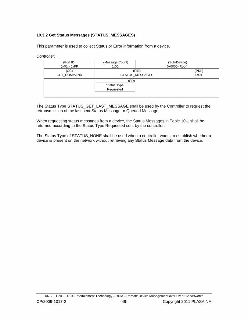
ANSI E1.20 – 2010, Entertainment Technology – RDM – Remote Device Management over DMX512 Networks
CP/2009-1017r2 -49- Copyright 2011 PLASA NA
10.3.2 Get Status Messages (STATUS_MESSAGES)
This parameter is used to collect Status or Error information from a device.
Controller:
(Port ID)
0x01 - 0xFF
(Message Count)
0x00
(Sub-Device)
0x0000 (Root)
(CC)
GET_COMMAND
(PID)
STATUS_MESSAGES
(PDL)
0x01
(PD)
Status Type
Requested
The Status Type STATUS_GET_LAST_MESSAGE shall be used by the Controller to request the retransmission of the last sent Status Message or Queued Message.
When requesting status messages from a device, the Status Messages in Table 10-1 shall be returned according to the Status Type Requested sent by the controller.
The Status Type of STATUS_NONE shall be used when a controller wants to establish whether a device is present on the network without retrieving any Status Message data from the device.

ANSI E1.20 – 2010, Entertainment Technology – RDM – Remote Device Management over DMX512 Networks
CP/2009-1017r2 -50- Copyright 2011 PLASA NA
Response:
(Response Type)
ACK / ACK_OVERFLOW
(Message Count)
0x00-0xFF
(Sub-Device)
0x0000
(CC)
GET_COMMAND_
RESPONSE
(PID)
STATUS_MESSAGES
(PDL)
Variable (0x00 – 0xE1)
(PD)
Status Message # 1
Sub-Device ID (16-bit)
Status Type
Status Message ID
(16-bit)
Data Value 1
(16-bit)
Data Value 2
(16-bit)
Status Message # 2
Sub-Device ID (16-bit)
Status Type
Status Message ID
(16-bit)
Data Value 1
(16-bit)
Data Value 2
(16-bit)
Status Message # n
Sub-Device ID (16-bit)
Status Type
Status Message ID
(16-bit)
Data Value 1
(16-bit)
Data Value 2
(16-bit)
The response is a packed list of all status messages for the device. The total number of messages is calculated by dividing the PDL by 9. Each status message shall be a fixed length of 9 bytes.
Due to the maximum packet length limitation, the total number of status messages sent within a single message cannot exceed 25.
The responder shall maintain reported status information until it has been successfully delivered to the controller. Status is considered successfully delivered when the responder receives a Status Type Requested other than STATUS_GET_LAST_MESSAGE.
The previously delivered status messages shall be cleared from the reporting queue once they have been successfully delivered to the Controller.

ANSI E1.20 – 2010, Entertainment Technology – RDM – Remote Device Management over DMX512 Networks
CP/2009-1017r2 -51- Copyright 2011 PLASA NA
10.3.2.1 Sub-Device ID
In a system containing sub-devices, the Sub-Device field shall be used to indicate the sub-device to which the status message belongs. If the status message does not reference a particular sub-device the field shall be set to 0x0000, to reference the root device.
10.3.2.2 Status Type
The Status Type is used to identify the severity of the condition. The message shall be reported with a status type of: STATUS_ADVISORY, STATUS_ADVISORY_CLEARED, STATUS_WARNING, STATUS_WARNING_CLEARED, STATUS_ERROR, or STATUS_ERROR_CLEARED.
Status Type _CLEARED responses allow for the clearing or resolution of a status condition to be reported by devices that support this capability.
.
Table 10-1: Required Response to Status Requests
Status Type Messages Returned
Status Type Requested
ERROR ERROR_ CLEARED
WARNING WARNING_ CLEARED
ADVISORY ADVISORY_ CLEARED
ERROR X X
WARNING X X X X
ADVISORY X X X X X X
NONE (not allowed
for use with QUEUED_MESSAGE)
All Status Types are enumerated in Table A-4.
10.3.2.3 Status Message ID
Status Message ID‘s within the range of 0x0000 — 0x7FFF are reserved for publicly defined Status Messages. More information on publicly defined Status Message ID‘s can be found in Appendix B.
Manufacturer Specific messages are in the range of 0x8000 — 0xFFDF. Each Manufacturer-specific Status ID shall have a unique meaning, which shall be consistent across all products having a given Manufacturer ID.
10.3.2.4 Data Value 1 and 2
Each Status Message supports the return of two separate data values relevant to the context of the specific message. The data value for ESTA public status messages is used to identify a property within the device to which the message corresponds. Each Data Value shall be a signed integer.

ANSI E1.20 – 2010, Entertainment Technology – RDM – Remote Device Management over DMX512 Networks
CP/2009-1017r2 -52- Copyright 2011 PLASA NA
For Manufacturer-specific messages, each Data Value field shall only represent a single parameter. It shall not be bit-encoded to represent multiple parameters.
Status ID‘s not using the Data Value fields shall set the fields with 0x0000.
10.3.3 Get Status ID Description (STATUS_ID_DESCRIPTION)
This parameter is used to request an ASCII text description of a given Status ID. The description may be up to 32 characters.
Controller:
(Port ID)
0x01 - 0xFF
(Message Count)
0x00
(Sub-Device)
0x0000 (Root)
(CC)
GET_COMMAND
(PID)
STATUS_ID_DESCRIPTION
(PDL)
0x02
(PD)
Status ID being Requested (16-bit)
Response:
(Response Type)
ACK
(Message Count)
0x00-0xFF
(Sub-Device)
0x0000
(CC)
GET_COMMAND_
RESPONSE
(PID)
STATUS_ID_DESCRIPTION
(PDL)
0 – 32
Number of characters being sent
(PD)
ASCII Text Field of variable size.
Refer to Appendix B for details on response string formatting and parsing.
10.3.4 Clear Status ID (CLEAR_STATUS_ID)
This parameter is used to clear the status message queue.
Controller:
(Port ID)
0x01 - 0xFF
(Message Count)
0x00
(Sub-Device)
0x0000 (Root) or 0x0001- 0x0200 or 0xFFFF
(CC)
SET_COMMAND
(PID)
CLEAR_STATUS_ID
(PDL)
0x00
(PD)
Not Present

ANSI E1.20 – 2010, Entertainment Technology – RDM – Remote Device Management over DMX512 Networks
CP/2009-1017r2 -53- Copyright 2011 PLASA NA
Response:
(Response Type)
ACK
(Message Count)
0x00-0xFF
(Sub-Device)
Copy of Controller SD
(CC)
SET_COMMAND_RESPONSE
(PID)
CLEAR_STATUS_ID
(PDL)
0x00
(PD)
Not Present
10.3.5 Get/Set Sub-Device Status Reporting Threshold (SUB_DEVICE_STATUS_REPORT_THRESHOLD)
This parameter is used to set the verbosity of Sub-Device reporting using the Status Type codes as enumerated in Table A-4 .
This feature is used to inhibit reports from, for example, a specific dimmer in a rack that is generating repeated errors.
Controller: (GET)
(Port ID)
0x01 - 0xFF
(Message Count)
0x00
(Sub-Device)
0x0001 – 0x0200
(CC)
GET_COMMAND
(PID)
SUB_DEVICE_STATUS_REPORT_THRESHOLD
(PDL)
0x00
(PD)
Not Present
Response:
(Response Type)
ACK
(Message Count)
0x00-0xFF
(Sub-Device)
Copy of Controller SD
(CC)
GET_COMMAND_
RESPONSE
(PID)
SUB_DEVICE_STATUS_REPORT_THRESHOLD
(PDL)
0x01
(PD)
Status Type
Controller: (SET)
(Port ID)
0x01 - 0xFF
(Message Count)
0x00
(Sub-Device)
0x0001 – 0x0200 or 0xFFFF
(CC)
SET_COMMAND
(PID)
SUB_DEVICE_STATUS_REPORT_THRESHOLD
(PDL)
0x01
(PD)
Status Type

ANSI E1.20 – 2010, Entertainment Technology – RDM – Remote Device Management over DMX512 Networks
CP/2009-1017r2 -54- Copyright 2011 PLASA NA
Response:
(Response Type)
ACK
(Message Count)
0x00-0xFF
(Sub-Device)
Copy of Controller SD
(CC)
SET_COMMAND_
RESPONSE
(PID)
SUB_DEVICE_STATUS_REPORT_THRESHOLD
(PDL)
0x00
(PD)
Not Present
RDM Information Messages include messages used to determine the RDM capabilities of the devices connected to the network.
10.4.1 Get Supported Parameters (SUPPORTED_PARAMETERS)
The SUPPORTED PARAMETERS message is used to retrieve a packed list of supported PIDs.
Controller:
(Port ID)
0x01 - 0xFF
(Message Count)
0x00
(Sub-Device)
0x0000 (Root) – 0x0200
(CC)
GET_COMMAND
(PID)
SUPPORTED_PARAMETERS
(PDL)
0x00
(PD)
Not Present
Response:
(Response Type)
ACK / ACK_OVERFLOW
(Message Count)
0x00-0xFF
(Sub-Device)
Copy of Controller SD
(CC)
GET_COMMAND_
RESPONSE
(PID)
SUPPORTED_PARAMETERS
(PDL)
Variable (0x00 – 0xE6)
(PD)
Packed List of 16-bit Parameter ID‘s supported
All Sub-Devices of a single Root Device shall report identical parameter lists although all parameters need not be implemented in each sub-device.
A Supported Parameters request sent to Sub-Device 0x0000 (Root) shall return the Parameters supported by the Root-Device. A Supported Parameters request sent to any other Sub-Device value (0x0001-0x0200) shall have an identical response as any other non-Root value Sub-Device. Thus, it is only required to request the Supported Parameters of the Root Device and a single Sub-Device, if Sub-Devices are supported.
10.4 RDM Information Messages

ANSI E1.20 – 2010, Entertainment Technology – RDM – Remote Device Management over DMX512 Networks
CP/2009-1017r2 -55- Copyright 2011 PLASA NA
Devices with the same Manufacturer ID, Device Model ID, and Software Version ID response for the DEVICE_INFO parameter shall report an identical list for the SUPPORTED_PARAMETERS message. This allows the controller to reduce the quantity of information stored for identical devices.
Manufacturer-Specific PIDs may or may not be included in the response.
PIDs that are included in the minimum support list, indicated by the ―Required‖ column of Table A-3, shall not be reported.

ANSI E1.20 – 2010, Entertainment Technology – RDM – Remote Device Management over DMX512 Networks
CP/2009-1017r2 -56- Copyright 2011 PLASA NA
10.4.2 Get Parameter Description (PARAMETER_DESCRIPTION)
This parameter is used to retrieve the definition of some manufacturer-specific PIDs. The purpose of this parameter is to allow a controller to retrieve enough information about the manufacturer-specific PID to generate Get and Set commands.
Controller:
(Port ID)
0x01 - 0xFF
(Message Count)
0x00
(Sub-Device)
0x0000 (Root)
(CC)
GET_COMMAND
(PID)
PARAMETER_DESCRIPTION
(PDL)
0x02
(PD)
PID # Requested
Response:
(Response Type)
ACK
(Message Count)
0x00-0xFF
(Sub-Device)
0x0000
(CC)
GET_COMMAND_RESPONSE
(PID)
PARAMETER_DESCRIPTION
(PDL)
0x14 – 0x34
(PD)
PID # Requested (16-bit)
PDL Size
Data Type
Command Class
Type
Unit
Prefix
Min Valid Value (32-bit)
Max Valid Value (32-bit)
Default Value (32-bit)
Description [Variable 0-32 Chars]
Data Description:
PID # Requested:
The manufacturer specific PID requested by the controller. Range 0x8000 to 0xFFDF.
PDL Size:
PDL Size defines the number used for the PDL field in all GET_RESPONSE and SET messages associated with this PID. In the case of the value of DS_ASCII, the PDL Size represents the maximum length of a variable sized ASCII string.

ANSI E1.20 – 2010, Entertainment Technology – RDM – Remote Device Management over DMX512 Networks
CP/2009-1017r2 -57- Copyright 2011 PLASA NA
Data Type:
Data Type defines the size of the data entries in the PD of the message for this PID. For example: unsigned 8-bit character versus signed 16-bit word. Table A-15 enumerates the field codes.
Command Class:
Command Class defines whether Get and or Set messages are implemented for the specified PID. Table A-16 enumerates the field codes.
Type:
This field no longer has any meaning and should be filled with 0x00 in the response. Controllers should ignore the contents of this field.
Unit:
Unit is an unsigned 8-bit value enumerated by Table A-13. It defines the SI (International System of units) unit of the specified PID data.
Prefix:
Prefix is an unsigned 8-bit value enumerated by Table A-14. It defines the SI Prefix and multiplication factor of the units.
Min Valid Value:
This is a 32-bit field that represents the lowest value that data can reach. The format of the number is defined by DATA TYPE. This field has no meaning for a Data Type of DS_BIT_FIELD or DS_ASCII. For Data Types less than 32-bits, the Most Significant Bytes shall be padded with 0x00 out to 32-bits. For example, an 8-bit data value of 0x12 shall be represented in the field as: 0x00000012.
Max Valid Value:
This is a 32-bit field that represents the highest value that data can reach. The format of the number is defined by DATA TYPE. This field has no meaning for a Data Type of DS_BIT_FIELD or DS_ASCII. For Data Types less than 32-bits, the Most Significant Bytes shall be padded with 0x00 out to 32-bits. For example, an 8-bit data value of 0x12 shall be represented in the field as: 0x00000012.
Default Value:
This is a 32-bit field that represents the default value of that data. This field has no meaning for a Data Type of DS_BIT_FIELD or DS_ASCII. The default value shall be within the minimum and maximum range. For Data Types less than 32-bits, the Most Significant Bytes shall be padded with 0x00 out to 32-bits. For example, an 8-bit data value of 0x12 shall be represented in the field as: 0x00000012.
Description:
The Description field is used to describe the function of the specified PID. This text field shall be variable up to 32 characters in length.

ANSI E1.20 – 2010, Entertainment Technology – RDM – Remote Device Management over DMX512 Networks
CP/2009-1017r2 -58- Copyright 2011 PLASA NA
10.5.1 Get Device Info (DEVICE_INFO)
This parameter is used to retrieve a variety of information about the device that is normally required by a controller.
Controller:
(Port ID)
0x01 - 0xFF
(Message Count)
0x00
(Sub-Device)
0x0000 (Root) or 0x0001- 0x0200
(CC)
GET_COMMAND
(PID)
DEVICE_INFO
(PDL)
0x00
(PD)
Not Present
Response:
(Response Type)
ACK
(Message Count)
0x00-0xFF
(Sub-Device)
Copy of Controller SD
(CC)
GET_COMMAND_RESPONSE
(PID)
DEVICE_INFO
(PDL)
0x13
(PD)
RDM Protocol Version (16-bit)
Device Model ID (16-bit)
Product Category (16-bit)
Software Version ID (32-bit)
DMX512 Footprint (16-bit)
DMX512 Personality (16-bit)
DMX512 Start Address (16-bit)
Sub-Device Count (16-bit)
Sensor Count
Data Description:
RDM Protocol Version:
This field contains the version number of the published RDM Standard supported by the device. The value for these version fields are controlled by this standard and any subsequent revisions or additions to this standard as issued in the future.
10.5 Product Information Messages
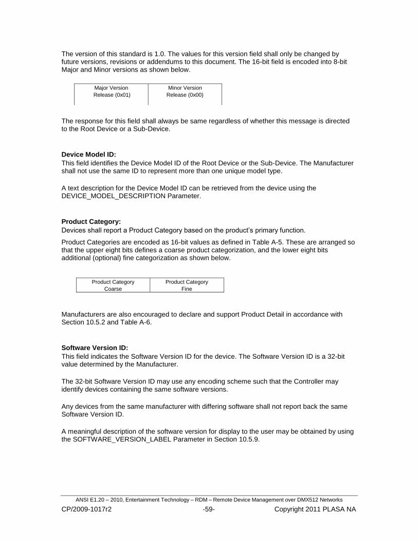
ANSI E1.20 – 2010, Entertainment Technology – RDM – Remote Device Management over DMX512 Networks
CP/2009-1017r2 -59- Copyright 2011 PLASA NA
The version of this standard is 1.0. The values for this version field shall only be changed by future versions, revisions or addendums to this document. The 16-bit field is encoded into 8-bit Major and Minor versions as shown below.
The response for this field shall always be same regardless of whether this message is directed to the Root Device or a Sub-Device.
Device Model ID:
This field identifies the Device Model ID of the Root Device or the Sub-Device. The Manufacturer shall not use the same ID to represent more than one unique model type.
A text description for the Device Model ID can be retrieved from the device using the DEVICE_MODEL_DESCRIPTION Parameter.
Product Category:
Devices shall report a Product Category based on the product‘s primary function.
Product Categories are encoded as 16-bit values as defined in Table A-5. These are arranged so that the upper eight bits defines a coarse product categorization, and the lower eight bits additional (optional) fine categorization as shown below.
Product Category
Coarse
Product Category
Fine
Manufacturers are also encouraged to declare and support Product Detail in accordance with Section 10.5.2 and Table A-6.
Software Version ID:
This field indicates the Software Version ID for the device. The Software Version ID is a 32-bit value determined by the Manufacturer.
The 32-bit Software Version ID may use any encoding scheme such that the Controller may identify devices containing the same software versions.
Any devices from the same manufacturer with differing software shall not report back the same Software Version ID.
A meaningful description of the software version for display to the user may be obtained by using the SOFTWARE_VERSION_LABEL Parameter in Section 10.5.9.
Major Version
Release (0x01)
Minor Version
Release (0x00)

ANSI E1.20 – 2010, Entertainment Technology – RDM – Remote Device Management over DMX512 Networks
CP/2009-1017r2 -60- Copyright 2011 PLASA NA
DMX512 Footprint:
This field specifies the DMX512 footprint (number of consecutive DMX512 slots required). This information can be used in conjunction with DMX_START_ADDRESS for auto-patching capabilities.
If the DEVICE_INFO message is directed to a Sub-Device, then the response for this field contains the DMX512 Footprint for that Sub-Device. If the message is sent to the Root Device, it is the Footprint for the Root Device itself. If the Device or Sub-Device does not utilize Null Start Code packets for any control or functionality then it shall report a Footprint of 0x0000.
The range for this field is from 0 – 512.
DMX512 Personality:
The DMX512 Personality fields are detailed in Section10.6.1. The 16-bit field is encoded into two 8-bit fields as shown below.
DMX512 Start Address:
The DMX512 Start Address field is detailed in Section 10.6.3.
If the Device or Sub-Device that this message is directed to has a DMX512 Footprint of 0, then this field shall be set to 0xFFFF.
Sub-Device Count:
This parameter is used to retrieve the number of Sub-Devices represented by the Root Device as described in Section 9.
The response for this field shall always be same regardless of whether this message is directed to the Root Device or a Sub-Device.
Sensor Count:
This field indicates the number of available sensors in a Root Device or Sub-Device. When this parameter is directed to a Sub-Device, the reply shall be identical for any Sub-Device owned by a specific Root Device.
When a device or sub-device is fitted with a single sensor, it would return a value of 0x01 for the Sensor Count. This sensor would then be addressed as Sensor Number 0x00 when using the other sensor-related parameter messages.
Current Personality Total # of Personalities
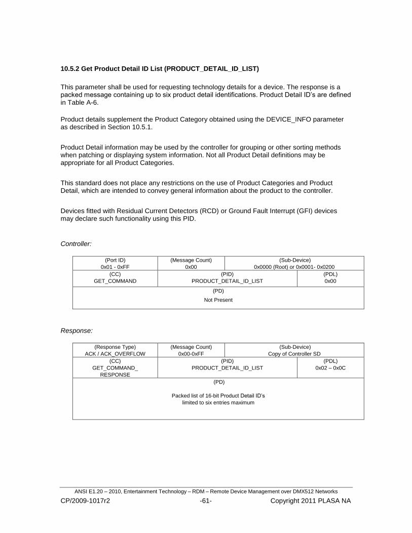
ANSI E1.20 – 2010, Entertainment Technology – RDM – Remote Device Management over DMX512 Networks
CP/2009-1017r2 -61- Copyright 2011 PLASA NA
10.5.2 Get Product Detail ID List (PRODUCT_DETAIL_ID_LIST)
This parameter shall be used for requesting technology details for a device. The response is a packed message containing up to six product detail identifications. Product Detail ID‘s are defined in Table A-6.
Product details supplement the Product Category obtained using the DEVICE_INFO parameter as described in Section 10.5.1.
Product Detail information may be used by the controller for grouping or other sorting methods when patching or displaying system information. Not all Product Detail definitions may be appropriate for all Product Categories.
This standard does not place any restrictions on the use of Product Categories and Product Detail, which are intended to convey general information about the product to the controller.
Devices fitted with Residual Current Detectors (RCD) or Ground Fault Interrupt (GFI) devices may declare such functionality using this PID.
Controller:
(Port ID)
0x01 - 0xFF
(Message Count)
0x00
(Sub-Device)
0x0000 (Root) or 0x0001- 0x0200
(CC)
GET_COMMAND
(PID)
PRODUCT_DETAIL_ID_LIST
(PDL)
0x00
(PD)
Not Present
Response:
(Response Type)
ACK / ACK_OVERFLOW
(Message Count)
0x00-0xFF
(Sub-Device)
Copy of Controller SD
(CC)
GET_COMMAND_
RESPONSE
(PID)
PRODUCT_DETAIL_ID_LIST
(PDL)
0x02 – 0x0C
(PD)
Packed list of 16-bit Product Detail ID‘s
limited to six entries maximum

ANSI E1.20 – 2010, Entertainment Technology – RDM – Remote Device Management over DMX512 Networks
CP/2009-1017r2 -62- Copyright 2011 PLASA NA
10.5.3 Get Device Model Description (DEVICE_MODEL_DESCRIPTION)
This parameter provides a text description of up to 32 characters for the device model type.
Controller:
(Port ID)
0x01 - 0xFF
(Message Count)
0x00
(Sub-Device)
0x0000 (Root) or 0x0001- 0x0200
(CC)
GET_COMMAND
(PID)
DEVICE_MODEL_DESCRIPTION
(PDL)
0x00
(PD)
Not Present
Response:
(Response Type)
ACK
(Message Count)
0x00-0xFF
(Sub-Device)
Copy of Controller SD
(CC)
GET_COMMAND_
RESPONSE
(PID)
DEVICE_MODEL_DESCRIPTION
(PDL)
0-32
Variable
(PD)
ASCII text Model description
Up to 32 characters.
10.5.4 Get Manufacturer Label (MANUFACTURER_LABEL)
This parameter provides an ASCII text response with the Manufacturer name for the device of up to 32 characters. The Manufacturer name must be consistent between all products manufactured within an ESTA Manufacturer ID.
Controller:
(Port ID)
0x01 - 0xFF
(Message Count)
0x00
(Sub-Device)
0x0000 (Root) or 0x0001- 0x0200
(CC)
GET_COMMAND
(PID)
MANUFACTURER_LABEL
(PDL)
0x00
(PD)
Not Present
Response:
(Response Type)
ACK
(Message Count)
0x00-0xFF
(Sub-Device)
Copy of Controller SD
(CC)
GET_COMMAND_
RESPONSE
(PID)
MANUFACTURER_LABEL
(PDL)
0-32
Variable
(PD)
ASCII text Manufacturer description
Up to 32 characters.

ANSI E1.20 – 2010, Entertainment Technology – RDM – Remote Device Management over DMX512 Networks
CP/2009-1017r2 -63- Copyright 2011 PLASA NA
10.5.5 Get/Set Device Label (DEVICE_LABEL)
This parameter provides a means of setting a descriptive label for each device. This may be used for identifying a dimmer rack number or specifying the device‘s location.
Controller: (GET)
(Port ID)
0x01 - 0xFF
(Message Count)
0x00
(Sub-Device)
0x0000 (Root) or 0x0001- 0x0200
(CC)
GET_COMMAND
(PID)
DEVICE_LABEL
(PDL)
0x00
(PD)
Not Present
Response:
(Response Type)
ACK
(Message Count)
0x00-0xFF
(Sub-Device)
Copy of Controller SD
(CC)
GET_COMMAND_
RESPONSE
(PID)
DEVICE_LABEL
(PDL)
0-32
Variable
(PD)
ASCII text label. Up to 32 characters.
Controller: (SET)
(Port ID)
0x01 - 0xFF
(Message Count)
0x00
(Sub-Device)
0x0000 (Root) or 0x0001- 0x0200 or 0xFFFF
(CC)
SET_COMMAND
(PID)
DEVICE_LABEL
(PDL)
0-32
Variable
(PD)
ASCII text label. Up to 32 characters.
Response:
(Response Type)
ACK
(Message Count)
0x00-0xFF
(Sub-Device)
Copy of Controller SD
(CC)
SET_COMMAND_
RESPONSE
(PID)
DEVICE_LABEL
(PDL)
0x00
(PD)
Not Present

ANSI E1.20 – 2010, Entertainment Technology – RDM – Remote Device Management over DMX512 Networks
CP/2009-1017r2 -64- Copyright 2011 PLASA NA
10.5.6 Get/Set Factory Defaults (FACTORY_DEFAULTS)
This parameter is used to instruct a device to revert to its Factory Default user settings or configuration as determined by the Manufacturer.
Controller: (GET)
(Port ID)
0x01 - 0xFF
(Message Count)
0x00
(Sub-Device)
0x0000 (Root) or 0x0001- 0x0200
(CC)
GET_COMMAND
(PID)
FACTORY_DEFAULTS
(PDL)
0x00
(PD)
Not Present
Response:
(Response Type)
ACK
(Message Count)
0x00-0xFF
(Sub-Device)
Copy of Controller SD
(CC)
GET_COMMAND_
RESPONSE
(PID)
FACTORY_DEFAULTS
(PDL)
0x01
(PD)
True/False (1/0)
Controller: (SET)
(Port ID)
0x01 - 0xFF
(Message Count)
0x00
(Sub-Device)
0x0000 (Root) or 0x0001 – 0x0200 or 0xFFFF
(CC)
SET_COMMAND
(PID)
FACTORY_DEFAULTS
(PDL)
0x00
(PD)
Not Present
Response:
(Response Type)
ACK
(Message Count)
0x00-0xFF
(Sub-Device)
Copy of Controller SD
(CC)
SET_COMMAND_
RESPONSE
(PID)
FACTORY_DEFAULTS
(PDL)
0x00
(PD)
Not Present
The Parameter Data value is used in the GET_COMMMAND_RESPONSE message to indicate whether the device is currently set to the Factory Defaults.

ANSI E1.20 – 2010, Entertainment Technology – RDM – Remote Device Management over DMX512 Networks
CP/2009-1017r2 -65- Copyright 2011 PLASA NA
10.5.7 Get Language Capabilities (LANGUAGE_CAPABILITIES)
This parameter is used to identify languages that the device supports for using the LANGUAGE parameter. The response contains a packed message of 2 character Language Codes as defined by ISO 639-1. International Standard ISO 639-1, Code for the representation of names of languages - Part 1: Alpha 2 code.
Controller:
(Port ID)
0x01 - 0xFF
(Message Count)
0x00
(Sub-Device)
0x0000 (Root) or 0x0001- 0x0200
(CC)
GET_COMMAND
(PID)
LANGUAGE_CAPABILITIES
(PDL)
0x00
(PD)
Not Present
Response:
(Response Type)
ACK / ACK_OVERFLOW
(Message Count)
0x00-0xFF
(Sub-Device)
Copy of Controller SD
(CC)
GET_COMMAND_
RESPONSE
(PID)
LANGUAGE_CAPABILITIES
(PDL)
Variable (0x00 – 0xE6)
(PD)
Packed List of 2 character Language codes

ANSI E1.20 – 2010, Entertainment Technology – RDM – Remote Device Management over DMX512 Networks
CP/2009-1017r2 -66- Copyright 2011 PLASA NA
10.5.8 Get/Set Language (LANGUAGE)
This parameter is used to change the language of the messages from the device. Supported languages of the device can be determined by the LANGUAGE_CAPABILITIES.
The Language Codes are 2 character alpha codes as defined by ISO 639-1. International Standard ISO 639-1, Code for the representation of names of languages - Part 1: Alpha 2 code.
Controller: (GET)
(Port ID)
0x01 - 0xFF
(Message Count)
0x00
(Sub-Device)
0x0000 (Root) or 0x0001- 0x0200
(CC)
GET_COMMAND
(PID)
LANGUAGE
(PDL)
0x00
(PD)
Not Present
Response:
(Response Type)
ACK
(Message Count)
0x00-0xFF
(Sub-Device)
Copy of Controller SD
(CC)
GET_COMMAND_
RESPONSE
(PID)
LANGUAGE
(PDL)
0x02
(PD)
2 character alpha code for ISO 639-1
Controller: (SET)
(Port ID)
0x01 - 0xFF
(Message Count)
0x00
(Sub-Device)
0x0000 (Root) or 0x0001- 0x0200 or 0xFFFF
(CC)
SET_COMMAND
(PID)
LANGUAGE
(PDL)
0x02
(PD)
2 character alpha code for ISO 639-1
Response:
(Response Type)
ACK
(Message Count)
0x00-0xFF
(Sub-Device)
Copy of Controller SD
(CC)
SET_COMMAND_
RESPONSE
(PID)
LANGUAGE
(PDL)
0x00
(PD)
Not Present
Set Language Code to 0x0000 to reset device to Default Language.

ANSI E1.20 – 2010, Entertainment Technology – RDM – Remote Device Management over DMX512 Networks
CP/2009-1017r2 -67- Copyright 2011 PLASA NA
10.5.9 Get Software Version Label (SOFTWARE_VERSION_LABEL)
This parameter is used to get a descriptive ASCII text label for the device‘s operating software version. The descriptive text returned by this parameter is intended for display to the user. The label may be up to 32 characters.
The Software Version ID field from the DEVICE_INFO parameter should be used for comparing devices from the same Manufacturer with the same Device Model ID to determine if they are running identical software versions.
Controller:
(Port ID)
0x01 – 0xFF
(Message Count)
0x00
(Sub-Device)
0x0000 (Root) or 0x0001- 0x0200
(CC)
GET_COMMAND
(PID)
SOFTWARE_VERSION_LABEL
(PDL)
0x00
(PD)
Not Present
Response:
(Response Type)
ACK
(Message Count)
0x00-0xFF
(Sub-Device)
Copy of Controller SD
(CC)
GET_COMMAND_
RESPONSE
(PID)
SOFTWARE_VERSION_LABEL
(PDL)
0 – 32
Variable
(PD)
ASCII text Software Version Label
Up to 32 characters.

ANSI E1.20 – 2010, Entertainment Technology – RDM – Remote Device Management over DMX512 Networks
CP/2009-1017r2 -68- Copyright 2011 PLASA NA
10.5.10 Get Boot Software Version ID (BOOT_SOFTWARE_VERSION_ID)
This parameter is used to retrieve the unique Boot Software Version ID for the device. The Boot Software Version ID is a 32-bit value determined by the Manufacturer.
The 32-bit Boot Software Version ID may use any encoding scheme such that the Controller may identify devices containing the same boot software versions.
Any devices from the same manufacturer with differing boot software shall not report back the same Boot Software Version ID.
A meaningful description of the boot software version for display to the user may be obtained by using the BOOT_SOFTWARE_VERSION_LABEL Parameter in Section 10.5.11.
Controller: (GET)
(Port ID)
0x01 - 0xFF
(Message Count)
0x00
(Sub-Device)
0x0000 (Root) or 0x0001- 0x0200
(CC)
GET_COMMAND
(PID)
BOOT_SOFTWARE_VERSION_ID
(PDL)
0x00
(PD)
Not Present
Response:
(Response Type)
ACK
(Message Count)
0x00-0xFF
(Sub-Device)
Copy of Controller SD
(CC)
GET_COMMAND_
RESPONSE
(PID)
BOOT_SOFTWARE_VERSION_ID
(PDL)
0x04
(PD)
Boot Software Version ID (32-bit)

ANSI E1.20 – 2010, Entertainment Technology – RDM – Remote Device Management over DMX512 Networks
CP/2009-1017r2 -69- Copyright 2011 PLASA NA
10.5.11 Get Boot Software Version Label (BOOT_SOFTWARE_VERSION_LABEL)
This parameter is used to get a descriptive ASCII text label for the Boot Version of the software for Devices that support this functionality. The descriptive text returned by this parameter is intended for display to the user. The label may be up to 32 characters.
The BOOT_SOFTWARE_VERSION_ID parameter should be used for comparing devices from the same Manufacturer with the same Device Model ID to determine if they are running identical boot software versions.
Controller:
(Port ID)
0x01 – 0xFF
(Message Count)
0x00
(Sub-Device)
0x0000 (Root) or 0x0001- 0x0200
(CC)
GET_COMMAND
(PID)
BOOT_SOFTWARE_VERSION_LABEL
(PDL)
0x00
(PD)
Not Present
Response:
(Response Type)
ACK
(Message Count)
0x00-0xFF
(Sub-Device)
Copy of Controller SD
(CC)
GET_COMMAND_
RESPONSE
(PID)
BOOT_SOFTWARE_VERSION_LABEL
(PDL)
0 – 32
Variable
(PD)
ASCII text Software Boot Version Label
Up to 32 characters.
10.6.1 Get/Set DMX512 Personality (DMX_PERSONALITY)
This parameter is used to set the responder‘s DMX512 Personality. Many devices such as moving lights have different DMX512 ―Personalities‖. Many RDM parameters may be affected by changing personality.
The DMX512 Personality can also be retrieved as part of the DEVICE_INFO Parameter Message in Section 10.5.1.
The GET_COMMAND_RESPONSE message includes the current DMX512 Personality setting and also the total number of personalities available. These personalities shall be consecutively numbered within the responder starting from 1.
10.6 DMX512 Setup Messages

ANSI E1.20 – 2010, Entertainment Technology – RDM – Remote Device Management over DMX512 Networks
CP/2009-1017r2 -70- Copyright 2011 PLASA NA
Controller: (GET)
(Port ID)
0x01 - 0xFF
(Message Count)
0x00
(Sub-Device)
0x0000 (Root) or 0x0001- 0x0200
(CC)
GET_COMMAND
(PID)
DMX_PERSONALITY
(PDL)
0x00
(PD)
Not Present
Response:
(Response Type)
ACK
(Message Count)
0x00-0xFF
(Sub-Device)
Copy of Controller SD
(CC)
GET_COMMAND_
RESPONSE
(PID)
DMX_PERSONALITY
(PDL)
0x02
(PD)
Current Personality # of Personalities
Controller: (SET)
(Port ID)
0x01 - 0xFF
(Message Count)
0x00
(Sub-Device)
0x0000 (Root) or 0x0001- 0x0200 or 0xFFFF
(CC)
SET_COMMAND
(PID)
DMX_PERSONALITY
(PDL)
0x01
(PD)
Personality
Response:
(Response Type)
ACK
(Message Count)
0x00-0xFF
(Sub-Device)
Copy of Controller SD
(CC)
SET_COMMAND_
RESPONSE
(PID)
DMX_PERSONALITY
(PDL)
0x00
(PD)
Not Present
The DMX512 Slot Footprint needed can be accessed from the DMX512 Footprint field in the DEVICE_INFO Parameter. Text descriptions for a given personality can be retrieved using the DMX_PERSONALITY_DESCRIPTION Parameter.

ANSI E1.20 – 2010, Entertainment Technology – RDM – Remote Device Management over DMX512 Networks
CP/2009-1017r2 -71- Copyright 2011 PLASA NA
10.6.2 Get DMX512 Personality Description (DMX_PERSONALITY_DESCRIPTION)
This parameter is used to get a descriptive ASCII text label for a given DMX512 Personality. The label may be up to 32 characters.
Controller:
(Port ID)
0x01 - 0xFF
(Message Count)
0x00
(Sub-Device)
0x0000 (Root) or 0x0001- 0x0200
(CC)
GET_COMMAND
(PID)
DMX_PERSONALITY_DESCRIPTION
(PDL)
0x01
(PD)
Personality Requested
Response:
(Response Type)
ACK
(Message Count)
0x00-0xFF
(Sub-Device)
Copy of Controller SD
(CC)
GET_COMMAND_
RESPONSE
(PID)
DMX_PERSONALITY_DESCRIPTION
(PDL)
3 – 35
(3 + Number of characters sent)
(PD)
Personality Requested
DMX512 Slots Required
0-512 (16-bit)
ASCII Text Field of variable size
The Response data contains the Personality Requested, the DMX512 Footprint for that Personality, along with up to 32 characters of description.

ANSI E1.20 – 2010, Entertainment Technology – RDM – Remote Device Management over DMX512 Networks
CP/2009-1017r2 -72- Copyright 2011 PLASA NA
10.6.3 Get/Set DMX512 Starting Address (DMX_START_ADDRESS)
This parameter is used to set or get the DMX512 start address.
The DMX512 Starting Address can also be retrieved as part of the DEVICE_INFO Parameter Message in Section 10.5.1.
When this message is directed to a Root Device or Sub-Device that has a DMX512 Footprint of 0 for that Root or Sub-Device, then the response shall be set to 0xFFFF. The returned data represents the address in the range 1 to 512.
Controller: (GET)
(Port ID)
0x01 - 0xFF
(Message Count)
0x00
(Sub-Device)
0x0000 (Root) or 0x0001- 0x0200
(CC)
GET_COMMAND
(PID)
DMX_START_ADDRESS
(PDL)
0x00
(PD)
Not Present
Response:
(Response Type)
ACK
(Message Count)
0x00-0xFF
(Sub-Device)
Copy of Controller SD
(CC)
GET_COMMAND_
RESPONSE
(PID)
DMX_START_ADDRESS
(PDL)
0x02
(PD)
DMX512 Address
1-512, 0xFFFF (16-bit)
Controller: (SET)
(Port ID)
0x01 - 0xFF
(Message Count)
0x00
(Sub-Device)
0x0000 (Root) or 0x0001- 0x0200 or 0xFFFF
(CC)
SET_COMMAND
(PID)
DMX_START_ADDRESS
(PDL)
0x02
(PD)
DMX512 Address
1-512 (16-bit)
Response:
(Response Type)
ACK
(Message Count)
0x00-0xFF
(Sub-Device)
Copy of Controller SD
(CC)
SET_COMMAND_
RESPONSE
(PID)
DMX_START_ADDRESS
(PDL)
0x00
(PD)
Not Present

ANSI E1.20 – 2010, Entertainment Technology – RDM – Remote Device Management over DMX512 Networks
CP/2009-1017r2 -73- Copyright 2011 PLASA NA
10.6.4 Get Slot Info (SLOT_INFO)
This parameter is used to retrieve basic information about the functionality of the DMX512 slots used to control the device. The response is a packed list of Slot Label ID‘s referencing into the Slot Labels table. See Appendix C for more information on Slot Type and Slot Label ID‘s.
Controller:
(Port ID)
0x01 - 0xFF
(Message Count)
0x00
(Sub-Device)
0x0000 (Root) or 0x0001- 0x0200
(CC)
GET_COMMAND
(PID)
SLOT_INFO
(PDL)
0x00
(PD)
Not Present
Response:
(Response Type)
ACK / ACK_OVERFLOW
(Message Count)
0x00-0xFF
(Sub-Device)
Copy of Controller SD
(CC)
GET_COMMAND_
RESPONSE
(PID)
SLOT_INFO
(PDL)
Variable (0x00 – 0xE6)
(PD)
Slot Offset 0
0 (16-bit) Slot Type
Slot Label ID (16-bit)
Slot Offset 1
1 (16-bit) Slot Type
Slot Label ID (16-bit)
Slot Offset n
N (16-bit) Slot Type
Slot Label ID (16-bit)
The Slot Offset is a reference to the offset from the DMX512 Starting Address for the device or Sub-Device described by the Slot Label ID. The Slot Offset for the first slot of a device (i.e. the DMX512 Starting Address) is 0. If a device skips or does not use all slots within its footprint range, then those slots shall not be reported in this message.
The Slot Type field indicates whether the slot is primary or secondary. A primary type slot refers to the basic parameter, such as intensity or pan. The slots have a type of ST_PRIMARY, and the Slot ID/Offset field contains a Slot ID. A secondary type slot is an additional slot related to a primary parameter. For secondary types, the Slot ID/Offset field contains a slot offset for the parameter to which it relates. For example, a 16-bit pan function in slots 1 and 2 would use ST_PRIMARY/SD_PAN for slot 1 and ST_SEC_FINE/1 for slot 2. If a secondary slot relates to more than one primary slot, it should reference the first applicable slot. Refer to Appendix C for more information on defined Slot Types and Slot IDs.

ANSI E1.20 – 2010, Entertainment Technology – RDM – Remote Device Management over DMX512 Networks
CP/2009-1017r2 -74- Copyright 2011 PLASA NA
A fixture with multiple parameters of the same type should report multiple slots with the same code. For example, a fixture with two static gobo wheels would report two slots of ST_PRIMARY/SD_STATIC_GOBO_WHEEL, which a controller could then interpret as Static Gobo Wheel 1 and Static Gobo Wheel 2.
A Slot Label ID of 0xFFFF indicates that the description for that slot offset is only available by using the SLOT_DESCRIPTION parameter.
10.6.5 Get Slot Description (SLOT_DESCRIPTION)
This parameter is used for requesting an ASCII text description for DMX512 slot offsets.
If the country code of the device is set to the English language, then the text returned should be similar to the description as defined in Table C-2.
If the responder does not support the Slot number requested, or cannot provide a text description for a slot number that it does support, the responder shall respond with NR_DATA_OUT_OF_RANGE.
Controller:
(Port ID)
0x01 - 0xFF
(Message Count)
0x00
(Sub-Device)
0x0000 (Root) or 0x0001- 0x0200
(CC)
GET_COMMAND
(PID)
SLOT_DESCRIPTION
(PDL)
0x02
(PD)
Slot # Requested (16-bit)
Response:
(Response Type)
ACK
(Message Count)
0x00-0xFF
(Sub-Device)
Copy of Controller SD
(CC)
GET_COMMAND_
RESPONSE
(PID)
SLOT_DESCRIPTION
(PDL)
2-34
(2+Number of characters being sent)
(PD)
Slot # Requested (16-bit)
ASCII Text Field of variable size up to 32 characters
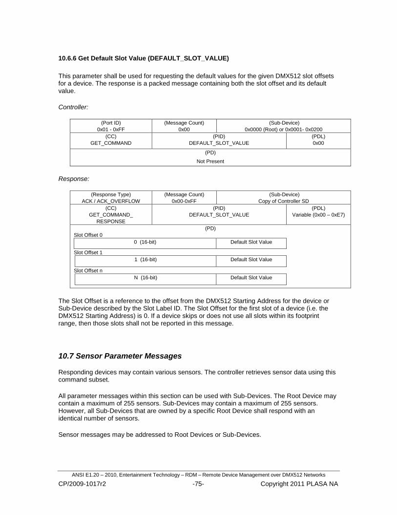
ANSI E1.20 – 2010, Entertainment Technology – RDM – Remote Device Management over DMX512 Networks
CP/2009-1017r2 -75- Copyright 2011 PLASA NA
10.6.6 Get Default Slot Value (DEFAULT_SLOT_VALUE)
This parameter shall be used for requesting the default values for the given DMX512 slot offsets for a device. The response is a packed message containing both the slot offset and its default value.
Controller:
(Port ID)
0x01 - 0xFF
(Message Count)
0x00
(Sub-Device)
0x0000 (Root) or 0x0001- 0x0200
(CC)
GET_COMMAND
(PID)
DEFAULT_SLOT_VALUE
(PDL)
0x00
(PD)
Not Present
Response:
(Response Type)
ACK / ACK_OVERFLOW
(Message Count)
0x00-0xFF
(Sub-Device)
Copy of Controller SD
(CC)
GET_COMMAND_
RESPONSE
(PID)
DEFAULT_SLOT_VALUE
(PDL)
Variable (0x00 – 0xE7)
(PD)
Slot Offset 0
0 (16-bit) Default Slot Value
Slot Offset 1
1 (16-bit) Default Slot Value
Slot Offset n
N (16-bit) Default Slot Value
The Slot Offset is a reference to the offset from the DMX512 Starting Address for the device or Sub-Device described by the Slot Label ID. The Slot Offset for the first slot of a device (i.e. the DMX512 Starting Address) is 0. If a device skips or does not use all slots within its footprint range, then those slots shall not be reported in this message.
Responding devices may contain various sensors. The controller retrieves sensor data using this command subset.
All parameter messages within this section can be used with Sub-Devices. The Root Device may contain a maximum of 255 sensors. Sub-Devices may contain a maximum of 255 sensors. However, all Sub-Devices that are owned by a specific Root Device shall respond with an identical number of sensors.
Sensor messages may be addressed to Root Devices or Sub-Devices.
10.7 Sensor Parameter Messages

ANSI E1.20 – 2010, Entertainment Technology – RDM – Remote Device Management over DMX512 Networks
CP/2009-1017r2 -76- Copyright 2011 PLASA NA
Valid sensor numbers are in the range from 0x00 – 0xFE. The sensor number 0xFF is used to address all sensors. The number of sensors present in a device can be retrieved using the DEVICE_INFO Parameter.
The number of sensors fitted to a responding device is obtained as part of the GET:DEVICE_INFO response.
10.7.1 Get Sensor Definition (SENSOR_DEFINITION)
This parameter is used to retrieve the definition of a specific sensor. When this parameter is directed to a Sub-Device, the reply shall be identical for any given sensor number in all Sub-Devices owned by a specific Root Device.
Controller:
(Port ID)
0x01 - 0xFF
(Message Count)
0x00
(Sub-Device)
0x0000 (Root) or 0x0001- 0x0200
(CC)
GET_COMMAND
(PID)
SENSOR_DEFINITION
(PDL)
0x01
(PD)
Sensor # Requested
Response:
(Response Type)
ACK
(Message Count)
0x00-0xFF
(Sub-Device)
Copy of Controller SD
(CC)
GET_COMMAND_RESPONSE
(PID)
SENSOR_DEFINITION
(PDL)
0x0D – 0x2D
(PD)
Sensor # Requested
Type
Unit
Prefix
Range Minimum Value (16-bit)
Range Maximum Value (16-bit)
Normal Minimum Value (16-bit)
Normal Maximum Value (16-bit)
Recorded Value Support
Description [Variable 0-32 chars]
Data Description:
Sensor Number:
The sensor number requested is in the range from 0x00 to 0xFE.
Type:
Type is an unsigned 8-bit value enumerated by Table A-12. It defines the type of data that is measured by the sensor.

ANSI E1.20 – 2010, Entertainment Technology – RDM – Remote Device Management over DMX512 Networks
CP/2009-1017r2 -77- Copyright 2011 PLASA NA
Unit:
Unit is an unsigned 8-bit value enumerated by Table A-13. It defines the SI unit of the sensor data.
Prefix:
Prefix is an unsigned 8 bit value enumerated by Table A-14. It defines the SI Prefix and multiplication factor of the units.
Range Minimum Value:
This is a 2‘s compliment signed 16-bit value that represents the lowest value the sensor can report. A value of –32768 indicates that the minimum is not defined.
Range Maximum Value:
This is a 2‘s compliment signed 16-bit value that represents the highest value the sensor can report. This also defines the maximum capacity. A value of +32767 indicates that the maximum is not defined.
Normal Minimum Value:
This is a 2‘s compliment signed 16-bit value that defines the lowest sensor value for which the device is in normal operation. A value of –32768 indicates that the minimum is not defined.
Normal Maximum Value:
This is a 2‘s compliment signed 16-bit value that defines the highest value that for which the device is in normal operation. A value of +32767 indicates that the maximum is not defined.
Recorded Value Support:
This field is a bit-masked field to indicate the support for recorded values.
The Detected and Recorded Value fields are described in Section 10.7.2 Get/Set Sensor.
Description:
The Description field is used to describe the function of the specified Sensor. This text field shall be variable up to 32 characters in length.
Bits 7-2
Reserved
(Always set to 0)
Bit 1
Lowest/Highest Detected Values Supported
Bit 0
Recorded Value Supported

ANSI E1.20 – 2010, Entertainment Technology – RDM – Remote Device Management over DMX512 Networks
CP/2009-1017r2 -78- Copyright 2011 PLASA NA
10.7.2 Get/Set Sensor (SENSOR_VALUE)
This parameter shall be used to retrieve or reset sensor data.
Controller: (GET) Sensor Data Retrieval
(Port ID)
0x01 - 0xFF
(Message Count)
0x00
(Sub-Device)
0x0000 (Root) or 0x0001- 0x0200
(CC)
GET_COMMAND
(PID)
SENSOR_VALUE
(PDL)
0x01
(PD)
Sensor # Requested
Response: (GET)
(Response Type)
ACK
(Message Count)
0x00-0xFF
(Sub-Device)
Copy of Controller SD
(CC)
GET_COMMAND_RESPONSE
(PID)
SENSOR_VALUE
(PDL)
0x09
(PD)
Sensor # Requested
Present Value (16-bit)
Lowest Detected Value (16-bit)
Highest Detected Value (16-bit)
Recorded Value (16-bit)
Controller: (SET) Sensor Data Reset
(Port ID)
0x01 - 0xFF
(Message Count)
0x00
(Sub-Device)
0x0000 (Root) or 0x0001- 0x0200 or 0xFFFF
(CC)
SET_COMMAND
(PID)
SENSOR_VALUE
(PDL)
0x01
(PD)
Sensor #
Response: (SET)
(Response Type)
ACK
(Message Count)
0x00-0xFF
(Sub-Device)
Copy of Controller SD
(CC)
SET_COMMAND_RESPONSE
(PID)
SENSOR_VALUE
(PDL)
0x09
(PD)
Sensor #
Present Value (16-bit)
Lowest Detected Value (16-bit)
Highest Detected Value (16-bit)
Recorded Value (16-bit)

ANSI E1.20 – 2010, Entertainment Technology – RDM – Remote Device Management over DMX512 Networks
CP/2009-1017r2 -79- Copyright 2011 PLASA NA
The SET_COMMAND may be used in conjunction with SENSOR_VALUE to reset or clear a given sensor. When a sensor is successfully reset the values for Present, Lowest/Highest, Recorded values in the response message shall all be equal.
Data Description:
Sensor Number:
The sensor number is in the range 0x00 to 0xFE. A value 0xFF is used to represent all sensors for the Set command.
The Sensor Value fields in the response to a SET Command sent to Sensor 0x0FF shall be ignored by the Controller. There is no requirement on a responder to provide specific values in this response.‖
Present Value:
This is a 2‘s compliment signed 16-bit value that represents the present value of the sensor data.
Lowest Detected Value:
This is a 2‘s compliment signed 16-bit value that represents the lowest value registered by the sensor. Support for this data is optional. If this value is not supported, then this field shall be set to 0x0000.
Highest Detected Value:
This is a 2‘s compliment signed 16-bit value that represents the highest value registered by the sensor. Support for this data is optional. If this value is not supported, then this field shall be set to 0x0000.
Recorded Value:
This is a 2‘s compliment signed 16-bit value that represents the value that was recorded when the last RECORD_SENSORS was issued. Support for this data is optional. If this value is not supported, then this field shall be set to 0x0000.

ANSI E1.20 – 2010, Entertainment Technology – RDM – Remote Device Management over DMX512 Networks
CP/2009-1017r2 -80- Copyright 2011 PLASA NA
10.7.3 Record Sensors (RECORD_SENSORS)
This parameter instructs devices such as dimming racks that monitor load changes to store the current value for monitoring sensor changes.
Controller: (Port ID)
0x01 - 0xFF
(Message Count)
0x00
(Sub-Device)
0x0000 (Root) or 0x0001- 0x0200 or 0xFFFF
(CC)
SET_COMMAND
(PID)
RECORD_SENSORS
(PDL)
0x01
(PD)
Sensor Number
Response:
(Response Type)
ACK
(Message Count)
0x00-0xFF
(Sub-Device)
Copy of Controller SD
(CC)
SET_COMMAND_RESPONSE
(PID)
RECORD_SENSORS
(PDL)
0x00
(PD)
Not Present
The Sensor Number identifies the sensor that is recorded. A Sensor Number value of 0xFF indicates that all sensors shall be recorded.
Any values recorded in this manner shall be available for retrieval using the GET: SENSOR_VALUE message.

ANSI E1.20 – 2010, Entertainment Technology – RDM – Remote Device Management over DMX512 Networks
CP/2009-1017r2 -81- Copyright 2011 PLASA NA
10.8.1 Get/Set Device Hours (DEVICE_HOURS)
This parameter is used to retrieve or set the number of hours of operation the device has been in use. Some devices may only support the GET_COMMAND for this operation and not allow the device‘s hours to be set.
The value for the Device Hours field shall be unsigned and not roll over when maximum value is reached.
Controller: (GET)
(Port ID)
0x01 - 0xFF
(Message Count)
0x00
(Sub-Device)
0x0000 (Root) or 0x0001- 0x0200
(CC)
GET_COMMAND
(PID)
DEVICE_HOURS
(PDL)
0x00
(PD)
Not Present
Response:
(Response Type)
ACK
(Message Count)
0x00-0xFF
(Sub-Device)
Copy of Controller SD
(CC)
GET_COMMAND_
RESPONSE
(PID)
DEVICE_HOURS
(PDL)
0x04
(PD)
Device Hours (32-bit)
Controller: (SET)
(Port ID)
0x01 - 0xFF
(Message Count)
0x00
(Sub-Device)
0x0000 (Root) or 0x0001- 0x0200 or 0xFFFF
(CC)
SET_COMMAND
(PID)
DEVICE_HOURS
(PDL)
0x04
(PD)
Device Hours (32-bit)
Response:
(Response Type)
ACK
(Message Count)
0x00-0xFF
(Sub-Device)
Copy of Controller SD
(CC)
SET_COMMAND_
RESPONSE
(PID)
DEVICE_HOURS
(PDL)
0x00
(PD)
Not Present
10.8 Power/Lamp Setting Parameter Messages

ANSI E1.20 – 2010, Entertainment Technology – RDM – Remote Device Management over DMX512 Networks
CP/2009-1017r2 -82- Copyright 2011 PLASA NA
10.8.2 Get/Set Lamp Hours (LAMP_HOURS)
This parameter is used to retrieve the number of lamp hours or to set the counter in the device to a specific starting value.
Controller: (GET)
(Port ID)
0x01 - 0xFF
(Message Count)
0x00
(Sub-Device)
0x0000 (Root) or 0x0001- 0x0200
(CC)
GET_COMMAND
(PID)
LAMP_HOURS
(PDL)
0x00
(PD)
Not Present
Response:
(Response Type)
ACK
(Message Count)
0x00-0xFF
(Sub-Device)
Copy of Controller SD
(CC)
GET_COMMAND_
RESPONSE
(PID)
LAMP_HOURS
(PDL)
0x04
(PD)
Lamp Hours (32-bit)
Controller: (SET)
(Port ID)
0x01 - 0xFF
(Message Count)
0x00
(Sub-Device)
0x0000 (Root) or 0x0001- 0x0200 or 0xFFFF
(CC)
SET_COMMAND
(PID)
LAMP_HOURS
(PDL)
0x04
(PD)
Lamp Hours (32-bit)
Response:
(Response Type)
ACK
(Message Count)
0x00-0xFF
(Sub-Device)
Copy of Controller SD
(CC)
SET_COMMAND_
RESPONSE
(PID)
LAMP_HOURS
(PDL)
0x00
(PD)
Not Present
The lamp hours are the total number of hours that the lamp has been on. The value for this field shall be unsigned and not roll over when maximum value is reached.

ANSI E1.20 – 2010, Entertainment Technology – RDM – Remote Device Management over DMX512 Networks
CP/2009-1017r2 -83- Copyright 2011 PLASA NA
10.8.3 Get/Set Lamp Strikes (LAMP_STRIKES)
This parameter is used to retrieve the number of lamp strikes or to set the counter in the device to a specific starting value.
Controller: (GET)
(Port ID)
0x01 - 0xFF
(Message Count)
0x00
(Sub-Device)
0x0000 (Root) or 0x0001- 0x0200
(CC)
GET_COMMAND
(PID)
LAMP_STRIKES
(PDL)
0x00
(PD)
Not Present
Response:
(Response Type)
ACK
(Message Count)
0x00-0xFF
(Sub-Device)
Copy of Controller SD
(CC)
GET_COMMAND_
RESPONSE
(PID)
LAMP_STRIKES
(PDL)
0x04
(PD)
Lamp Strikes (32-bit)
Controller: (SET)
(Port ID)
0x01 - 0xFF
(Message Count)
0x00
(Sub-Device)
0x0000 (Root) or 0x0001- 0x0200 or 0xFFFF
(CC)
SET_COMMAND
(PID)
LAMP_STRIKES
(PDL)
0x04
(PD)
Lamp Strikes (32-bit)
Response:
(Response Type)
ACK
(Message Count)
0x00-0xFF
(Sub-Device)
Copy of Controller SD
(CC)
SET_COMMAND_
RESPONSE
(PID)
LAMP_STRIKES
(PDL)
0x00
(PD)
Not Present
The lamp strikes are incremented each time the lamp is struck or switched on. The value for this field shall be unsigned and not roll over when maximum value is reached.

ANSI E1.20 – 2010, Entertainment Technology – RDM – Remote Device Management over DMX512 Networks
CP/2009-1017r2 -84- Copyright 2011 PLASA NA
10.8.4 Get/Set Lamp State (LAMP_STATE)
This parameter is used to retrieve or change the current operating state of the lamp.
Controller: (GET)
(Port ID)
0x01 - 0xFF
(Message Count)
0x00
(Sub-Device)
0x0000 (Root) or 0x0001- 0x0200
(CC)
GET_COMMAND
(PID)
LAMP_STATE
(PDL)
0x00
(PD)
Not Present
Response:
(Response Type)
ACK
(Message Count)
0x00-0xFF
(Sub-Device)
Copy of Controller SD
(CC)
GET_COMMAND_
RESPONSE
(PID)
LAMP_STATE
(PDL)
0x01
(PD)
Lamp State
Controller: (SET)
(Port ID)
0x01 - 0xFF
(Message Count)
0x00
(Sub-Device)
0x0000 (Root) or 0x0001- 0x0200 or 0xFFFF
(CC)
SET_COMMAND
(PID)
LAMP_STATE
(PDL)
0x01
(PD)
Lamp State
Response:
(Response Type)
ACK
(Message Count)
0x00-0xFF
(Sub-Device)
Copy of Controller SD
(CC)
SET_COMMAND_
RESPONSE
(PID)
LAMP_STATE
(PDL)
0x00
(PD)
Not Present
Lamp States are enumerated by Table A-8.

ANSI E1.20 – 2010, Entertainment Technology – RDM – Remote Device Management over DMX512 Networks
CP/2009-1017r2 -85- Copyright 2011 PLASA NA
10.8.5 Get/Set Lamp On Mode (LAMP_ON_MODE)
This parameter is used to retrieve or change the current Lamp On Mode. Lamp On Mode defines the conditions under which a lamp will be struck.
Controller: (GET)
(Port ID)
0x01 - 0xFF
(Message Count)
0x00
(Sub-Device)
0x0000 (Root) or 0x0001- 0x0200
(CC)
GET_COMMAND
(PID)
LAMP_ON_MODE
(PDL)
0x00
(PD)
Not Present
Response:
(Response Type)
ACK
(Message Count)
0x00-0xFF
(Sub-Device)
Copy of Controller SD
(CC)
GET_COMMAND_
RESPONSE
(PID)
LAMP_ON_MODE
(PDL)
0x01
(PD)
Lamp On Mode
Controller: (SET)
(Port ID)
0x01 - 0xFF
(Message Count)
0x00
(Sub-Device)
0x0000 (Root) or 0x0001- 0x0200 or 0xFFFF
(CC)
SET_COMMAND
(PID)
LAMP_ON_MODE
(PDL)
0x01
(PD)
Lamp On Mode
Response:
(Response Type)
ACK
(Message Count)
0x00-0xFF
(Sub-Device)
Copy of Controller SD
(CC)
SET_COMMAND_
RESPONSE
(PID)
LAMP_ON_MODE
(PDL)
0x00
(PD)
Not Present
Lamp On Modes are enumerated by Table A-9.

ANSI E1.20 – 2010, Entertainment Technology – RDM – Remote Device Management over DMX512 Networks
CP/2009-1017r2 -86- Copyright 2011 PLASA NA
10.8.6 Get/Set Device Power Cycles (DEVICE_POWER_CYCLES)
This parameter is used to retrieve or set the number of Power-up cycles for the device. Some devices may only support the GET_COMMAND for this operation and not allow the device‘s power-up cycles to be set.
The value for Power Cycle Count shall be unsigned and not roll over when maximum value is reached.
Controller: (GET)
(Port ID)
0x01 - 0xFF
(Message Count)
0x00
(Sub-Device)
0x0000 (Root) or 0x0001- 0x0200
(CC)
GET_COMMAND
(PID)
DEVICE_POWER_CYCLES
(PDL)
0x00
(PD)
Not Present
Response:
(Response Type)
ACK
(Message Count)
0x00-0xFF
(Sub-Device)
Copy of Controller SD
(CC)
GET_COMMAND_
RESPONSE
(PID)
DEVICE_POWER_CYCLES
(PDL)
0x04
(PD)
Power Cycle Count (32-bit)
Controller: (SET)
(Port ID)
0x01 - 0xFF
(Message Count)
0x00
(Sub-Device)
0x0000 (Root) or 0x0001- 0x0200 or 0xFFFF
(CC)
SET_COMMAND
(PID)
DEVICE_POWER_CYCLES
(PDL)
0x04
(PD)
Power Cycle Count (32-bit)
Response:
(Response Type)
ACK
(Message Count)
0x00-0xFF
(Sub-Device)
Copy of Controller SD
(CC)
SET_COMMAND_
RESPONSE
(PID)
DEVICE_POWER_CYCLES
(PDL)
0x00
(PD)
Not Present

ANSI E1.20 – 2010, Entertainment Technology – RDM – Remote Device Management over DMX512 Networks
CP/2009-1017r2 -87- Copyright 2011 PLASA NA
10.9.1 Get/Set Display Invert (DISPLAY_INVERT)
This parameter is used to retrieve or change the Display Invert setting. Invert is often used to rotate the display image by 180 degrees.
Controller: (GET)
(Port ID)
0x01 - 0xFF
(Message Count)
0x00
(Sub-Device)
0x0000 (Root) or 0x0001- 0x0200
(CC)
GET_COMMAND
(PID)
DISPLAY_INVERT
(PDL)
0x00
(PD)
Not Present
Response:
(Response Type)
ACK
(Message Count)
0x00-0xFF
(Sub-Device)
Copy of Controller SD
(CC)
GET_COMMAND_
RESPONSE
(PID)
DISPLAY_INVERT
(PDL)
0x01
(PD)
Off/On/Auto (0/1/2)
Controller: (SET)
(Port ID)
0x01 - 0xFF
(Message Count)
0x00
(Sub-Device)
0x0000 (Root) or 0x0001- 0x0200 0xFFFF
(CC)
SET_COMMAND
(PID)
DISPLAY_INVERT
(PDL)
0x01
(PD)
Off/On/Auto (0/1/2)
Response:
(Response Type)
ACK
(Message Count)
0x00-0xFF
(Sub-Device)
Copy of Controller SD
(CC)
SET_COMMAND_
RESPONSE
(PID)
DISPLAY_INVERT
(PDL)
0x00
(PD)
Not Present
The ‗Auto‘ setting is for devices that have the ability to automatically rotate the display based on the orientation of the device. Devices not supporting this functionality shall send a NACK Reason of NR_DATA_OUT_OF_RANGE.
10.9 Display Setting Parameter Messages

ANSI E1.20 – 2010, Entertainment Technology – RDM – Remote Device Management over DMX512 Networks
CP/2009-1017r2 -88- Copyright 2011 PLASA NA
10.9.2 Get/Set Display Level (DISPLAY_LEVEL)
This parameter is used to retrieve or change the Display Intensity setting.
Controller: (GET)
(Port ID)
0x01 - 0xFF
(Message Count)
0x00
(Sub-Device)
0x0000 (Root) or 0x0001- 0x0200
(CC)
GET_COMMAND
(PID)
DISPLAY_LEVEL
(PDL)
0x00
(PD)
Not Present
Response:
(Response Type)
ACK
(Message Count)
0x00-0xFF
(Sub-Device)
Copy of Controller SD
(CC)
GET_COMMAND_
RESPONSE
(PID)
DISPLAY_LEVEL
(PDL)
0x01
(PD)
Display Level
Controller: (SET)
(Port ID)
0x01 - 0xFF
(Message Count)
0x00
(Sub-Device)
0x0000 (Root) or 0x0001- 0x0200 or 0xFFFF
(CC)
SET_COMMAND
(PID)
DISPLAY_LEVEL
(PDL)
0x01
(PD)
Display Level
Response:
(Response Type)
ACK
(Message Count)
0x00-0xFF
(Sub-Device)
Copy of Controller SD
(CC)
SET_COMMAND_
RESPONSE
(PID)
DISPLAY_LEVEL
(PDL)
0x00
(PD)
Not Present
To turn the display off, Display Level shall be set to 0. To turn the display on full, Display Level shall be set to 0xFF. Any value in between represents a relative intensity setting. If the device does not support relative intensity settings, any non-zero value shall be interpreted as on.
The Display Level setting shall not override the use of the IDENTIFY_DEVICE Parameter for devices that use the display as part of the identification means.

ANSI E1.20 – 2010, Entertainment Technology – RDM – Remote Device Management over DMX512 Networks
CP/2009-1017r2 -89- Copyright 2011 PLASA NA
10.10.1 Get/Set Pan Invert (PAN_INVERT)
This parameter is used to retrieve or change the Pan Invert setting.
Controller: (GET)
(Port ID)
0x01 - 0xFF
(Message Count)
0x00
(Sub-Device)
0x0000 (Root) or 0x0001- 0x0200
(CC)
GET_COMMAND
(PID)
PAN_INVERT
(PDL)
0x00
(PD)
Not Present
Response:
(Response Type)
ACK
(Message Count)
0x00-0xFF
(Sub-Device)
Copy of Controller SD
(CC)
GET_COMMAND_
RESPONSE
(PID)
PAN_INVERT
(PDL)
0x01
(PD)
Off/On (0/1)
Controller: (SET)
(Port ID)
0x01 - 0xFF
(Message Count)
0x00
(Sub-Device)
0x0000 (Root) or 0x0001- 0x0200 or 0xFFFF
(CC)
SET_COMMAND
(PID)
PAN_INVERT
(PDL)
0x01
(PD)
Off/On (0/1)
Response:
(Response Type)
ACK
(Message Count)
0x00-0xFF
(Sub-Device)
Copy of Controller SD
(CC)
SET_COMMAND_
RESPONSE
(PID)
PAN_INVERT
(PDL)
0x00
(PD)
Not Present
10.10 Device Configuration Parameter Messages

ANSI E1.20 – 2010, Entertainment Technology – RDM – Remote Device Management over DMX512 Networks
CP/2009-1017r2 -90- Copyright 2011 PLASA NA
10.10.2 Get/Set Tilt Invert (TILT_INVERT)
This parameter is used to retrieve or change the Tilt Invert setting.
Controller: (GET)
(Port ID)
0x01 - 0xFF
(Message Count)
0x00
(Sub-Device)
0x0000 (Root) or 0x0001- 0x0200
(CC)
GET_COMMAND
(PID)
TILT_INVERT
(PDL)
0x00
(PD)
Not Present
Response:
(Response Type)
ACK
(Message Count)
0x00-0xFF
(Sub-Device)
Copy of Controller SD
(CC)
GET_COMMAND_
RESPONSE
(PID)
TILT_INVERT
(PDL)
0x01
(PD)
Off/On (0/1)
Controller: (SET)
(Port ID)
0x01 - 0xFF
(Message Count)
0x00
(Sub-Device)
0x0000 (Root) or 0x0001- 0x0200 or 0xFFFF
(CC)
SET_COMMAND
(PID)
TILT_INVERT
(PDL)
0x01
(PD)
Off/On (0/1)
Response:
(Response Type)
ACK
(Message Count)
0x00-0xFF
(Sub-Device)
Copy of Controller SD
(CC)
SET_COMMAND_
RESPONSE
(PID)
TILT_INVERT
(PDL)
0x00
(PD)
Not Present

ANSI E1.20 – 2010, Entertainment Technology – RDM – Remote Device Management over DMX512 Networks
CP/2009-1017r2 -91- Copyright 2011 PLASA NA
10.10.3 Get/Set Pan/Tilt Swap (PAN_TILT_SWAP)
This parameter is used to retrieve or change the Pan/Tilt Swap setting.
Controller: (GET)
(Port ID)
0x01 - 0xFF
(Message Count)
0x00
(Sub-Device)
0x0000 (Root) or 0x0001- 0x0200
(CC)
GET_COMMAND
(PID)
PAN_TILT_SWAP
(PDL)
0x00
(PD)
Not Present
Response:
(Response Type)
ACK
(Message Count)
0x00-0xFF
(Sub-Device)
Copy of Controller SD
(CC)
GET_COMMAND_
RESPONSE
(PID)
PAN_TILT_SWAP
(PDL)
0x01
(PD)
Off/On (0/1)
Controller: (SET)
(Port ID)
0x01 - 0xFF
(Message Count)
0x00
(Sub-Device)
0x0000 (Root) or 0x0001- 0x0200 or 0xFFFF
(CC)
SET_COMMAND
(PID)
PAN_TILT_SWAP
(PDL)
0x01
(PD)
Off/On (0/1)
Response:
(Response Type)
ACK
(Message Count)
0x00-0xFF
(Sub-Device)
Copy of Controller SD
(CC)
SET_COMMAND_
RESPONSE
(PID)
PAN_TILT_SWAP
(PDL)
0x00
(PD)
Not Present

ANSI E1.20 – 2010, Entertainment Technology – RDM – Remote Device Management over DMX512 Networks
CP/2009-1017r2 -92- Copyright 2011 PLASA NA
10.10.4 Get/Set Device Real-Time Clock (REAL_TIME_CLOCK)
This parameter is used to retrieve or set the real-time clock in a device.
Controller: (GET)
(Port ID)
0x01 - 0xFF
(Message Count)
0x00
(Sub-Device)
0x0000 (Root) or 0x0001- 0x0200
(CC)
GET_COMMAND
(PID)
REAL_TIME_CLOCK
(PDL)
0x00
(PD)
Not Present
Response:
(Response Type)
ACK
(Message Count)
0x00-0xFF
(Sub-Device)
Copy of Controller SD
(CC)
GET_COMMAND_
RESPONSE
(PID)
REAL_TIME_CLOCK
(PDL)
0x07
(PD)
Year (16-bit) Month Day
Hour Minute Second
Controller: (SET)
(Port ID)
0x01 - 0xFF
(Message Count)
0x00
(Sub-Device)
0x0000 (Root) or 0x0001- 0x0200 or 0xFFFF
(CC)
SET_COMMAND
(PID)
REAL_TIME_CLOCK
(PDL)
0x07
(PD)
Year (16-bit) Month Day
Hour Minute Second
Response:
(Response Type)
ACK
(Message Count)
0x00-0xFF
(Sub-Device)
Copy of Controller SD
(CC)
SET_COMMAND_
RESPONSE
(PID)
REAL_TIME_CLOCK
(PDL)
0x00
(PD)
Not Present
Date and Time fields shall follow the format from Table 10-2. Hours shall be encoded using 24 hour format.

ANSI E1.20 – 2010, Entertainment Technology – RDM – Remote Device Management over DMX512 Networks
CP/2009-1017r2 -93- Copyright 2011 PLASA NA
Table 10-2: Date and Time Ranges
Minimum Value Maximum Value
Year 2003 65535
Month 1 12
Day 1 31
Hour 0 23
Minute 0 59
10.11.1 Get/Set Identify Device (IDENTIFY_DEVICE)
This parameter is used for the user to physically identify the device represented by the UID.
The responder shall physically identify itself using a visible or audible action. For example, strobing a light or outputting fog.
The current state of a responders identification status may be obtained using a GET:IDENTIFY_DEVICE message.
Controller: (GET)
(Port ID)
0x01 - 0xFF
(Message Count)
0x00
(Sub-Device)
0x0000 (Root) or 0x0001- 0x0200
(CC)
GET_COMMAND
(PID)
IDENTIFY_DEVICE
(PDL)
0x00
(PD)
Not Present
Response:
(Response Type)
ACK
(Message Count)
0x00-0xFF
(Sub-Device)
Copy of Controller SD
(CC)
GET_COMMAND_RESPONSE
(PID)
IDENTIFY_DEVICE
(PDL)
0x01
(PD)
Identify State
Off/On (0/1)
10.11 Device Control Parameter Messages

ANSI E1.20 – 2010, Entertainment Technology – RDM – Remote Device Management over DMX512 Networks
CP/2009-1017r2 -94- Copyright 2011 PLASA NA
Controller: (SET)
(Port ID)
0x01 - 0xFF
(Message Count)
0x00
(Sub-Device)
0x0000 (Root) or 0x0001- 0x0200 or 0xFFFF
(CC)
SET_COMMAND
(PID)
IDENTIFY_DEVICE
(PDL)
0x01
(PD)
Identify Stop/Start (0/1)
Response:
(Response Type)
ACK
(Message Count)
0x00-0xFF
(Sub-Device)
Copy of Controller SD
(CC)
SET_COMMAND_RESPONSE
(PID)
IDENTIFY_DEVICE
(PDL)
0x00
(PD)
Not Present
10.11.2 Reset Device (RESET_DEVICE)
This parameter is used to instruct the responder to reset itself. This parameter shall also clear the Discovery Mute flag. A cold reset is the equivalent of removing and reapplying power to the device.
Controller:
(Port ID)
0x01 - 0xFF
(Message Count)
0x00
(Sub-Device)
0x0000 (Root) or 0x0001- 0x0200 or 0xFFFF
(CC)
SET_COMMAND
(PID)
RESET_DEVICE
(PDL)
0x01
(PD)
0x01 for Warm Reset
0xFF for Cold Reset
Response:
(Response Type)
ACK
(Message Count)
0x00-0xFF
(Sub-Device)
Copy of Controller SD
(CC)
SET_COMMAND_RESPONSE
(PID)
RESET_DEVICE
(PDL)
0x00
(PD)
Not Present

ANSI E1.20 – 2010, Entertainment Technology – RDM – Remote Device Management over DMX512 Networks
CP/2009-1017r2 -95- Copyright 2011 PLASA NA
10.11.3 Get/Set Power State (POWER_STATE)
This parameter is used to retrieve or change the current device Power State. Power State specifies the current operating mode of the device.
Controller: (GET)
(Port ID)
0x01 - 0xFF
(Message Count)
0x00
(Sub-Device)
0x0000 (Root) or 0x0001- 0x0200
(CC)
GET_COMMAND
(PID)
POWER_STATE
(PDL)
0x00
(PD)
Not Present
Response:
(Response Type)
ACK
(Message Count)
0x00-0xFF
(Sub-Device)
Copy of Controller SD
(CC)
GET_COMMAND_
RESPONSE
(PID)
POWER_STATE
(PDL)
0x01
(PD)
Power State
Controller: (SET)
(Port ID)
0x01 - 0xFF
(Message Count)
0x00
(Sub-Device)
0x0000 (Root) or 0x0001- 0x0200 or 0xFFFF
(CC)
SET_COMMAND
(PID)
POWER_STATE
(PDL)
0x01
(PD)
Power State
Response:
(Response Type)
ACK
(Message Count)
0x00-0xFF
(Sub-Device)
Copy of Controller SD
(CC)
SET_COMMAND_
RESPONSE
(PID)
POWER_STATE
(PDL)
0x00
(PD)
Not Present
Power State Modes are enumerated by Table A-11.

ANSI E1.20 – 2010, Entertainment Technology – RDM – Remote Device Management over DMX512 Networks
CP/2009-1017r2 -96- Copyright 2011 PLASA NA
10.11.4 Get/Set Perform Self Test (PERFORM_SELFTEST)
The PERFORM_SELFTEST message is used to execute any built in Self-Test routine that may be present. The test may run continuously until receiving a PERFORM_SELFTEST with a SELF_TEST_OFF value, or may exit upon completion.
The GET_COMMAND may be used to determine if any Self Tests are currently running. If any Self Tests are running the response flag shall be set to 0x01. A Self Test operation may return pass/fail status or other information by queuing a Status Message response.
Controller:
(Port ID)
0x01 - 0xFF
(Message Count)
0x00
(Sub-Device)
0x0000 (Root) or 0x0001- 0x0200
(CC)
GET_COMMAND
(PID)
PERFORM_SELFTEST
(PDL)
0x00
(PD)
Not Present
Response:
(Response Type)
ACK
(Message Count)
0x00-0xFF
(Sub-Device)
Copy of Controller SD
(CC)
GET_COMMAND_RESPONSE
(PID)
PERFORM_SELFTEST
(PDL)
0x01
(PD)
Self Tests Active TRUE/FALSE (1/0)
Controller:
(Port ID)
0x01 - 0xFF
(Message Count)
0x00
(Sub-Device)
0x0000 (Root) or 0x0001- 0x0200 or 0xFFFF
(CC)
SET_COMMAND
(PID)
PERFORM_SELFTEST
(PDL)
0x01
(PD)
Self Test #
The Parameter Data includes a value indicating the self-test to execute as shown in Table A-10.
Response:
(Response Type)
ACK
(Message Count)
0x00-0xFF
(Sub-Device)
Copy of Controller SD
(CC)
SET_COMMAND_RESPONSE
(PID)
PERFORM_SELFTEST
(PDL)
0x00
(PD)
Not Present

ANSI E1.20 – 2010, Entertainment Technology – RDM – Remote Device Management over DMX512 Networks
CP/2009-1017r2 -97- Copyright 2011 PLASA NA
10.11.5 Get Self Test Description (SELF_TEST_DESCRIPTION)
This parameter is used to get a descriptive ASCII text label for a given Self Test Operation. The label may be up to 32 characters.
Controller:
(Port ID)
0x01 - 0xFF
(Message Count)
0x00
(Sub-Device)
0x0000 (Root) or 0x0001- 0x0200
(CC)
GET_COMMAND
(PID)
SELF_TEST_DESCRIPTION
(PDL)
0x01
(PD)
Self Test # Requested
Response:
(Response Type)
ACK
(Message Count)
0x00-0xFF
(Sub-Device)
Copy of Controller SD
(CC)
GET_COMMAND_
RESPONSE
(PID)
SELF_TEST_DESCRIPTION
(PDL)
1-33
(1+Number of characters being sent)
(PD)
Self Test # Requested
ASCII text label. Up to 32 characters.

ANSI E1.20 – 2010, Entertainment Technology – RDM – Remote Device Management over DMX512 Networks
CP/2009-1017r2 -98- Copyright 2011 PLASA NA
10.11.6 Capture Preset (CAPTURE_PRESET)
This parameter is used to capture a static scene into a Preset within the responder. The actual data that is captured is beyond the scope of this standard. Upon receipt of this parameter the responder shall capture the scene and store it to the designated preset.
Fade and Wait times for building sequences may also be included. Times are in tenths of a second. When timing information is not required the fields shall be set to 0x00.
The Up Fade Time is the fade in time for the current scene and the Down Fade Time is the down fade for the previous scene or active look. The Wait Time is the time the device spends holding the current scene before proceeding to play the next scene when the presets are being played back as a sequence using PRESET_PLAYBACK_ALL.
Controller:
(Port ID)
0x01 - 0xFF
(Message Count)
0x00
(Sub-Device)
0x0000 (Root) or 0x0001- 0x0200 or 0xFFFF
(CC)
SET_COMMAND
(PID)
CAPTURE_PRESET
(PDL)
0x02 or 0x08
(PD)
Scene # (16-bit)
Up Fade Time (16-bit)
Down Fade Time (16-bit)
Wait Time (16-bit)
Response:
(Response Type)
ACK
(Message Count)
0x00-0xFF
(Sub-Device)
Copy of Controller SD
(CC)
SET_COMMAND_RESPONSE
(PID)
CAPTURE_PRESET
(PDL)
0x00
(PD)
Not Present

ANSI E1.20 – 2010, Entertainment Technology – RDM – Remote Device Management over DMX512 Networks
CP/2009-1017r2 -99- Copyright 2011 PLASA NA
10.11.7 Get/Set Preset Playback (PRESET_PLAYBACK)
This parameter is used to recall pre-recorded Presets.
Preset playback types are enumerated by Table A-7.
Controller: (GET)
(Port ID)
0x01 - 0xFF
(Message Count)
0x00
(Sub-Device)
0x0000 (Root) or 0x0001- 0x0200
(CC)
GET_COMMAND
(PID)
PRESET_PLAYBACK
(PDL)
0x00
(PD)
Not Present
Response:
(Response Type)
ACK
(Message Count)
0x00-0xFF
(Sub-Device)
Copy of Controller SD
(CC)
GET_COMMAND_
RESPONSE
(PID)
PRESET_PLAYBACK
(PDL)
0x03
(PD)
Mode (16-bit)
(OFF/ALL/Scene #)
Level (0x00-0xFF)
Controller: (SET)
(Port ID)
0x01 - 0xFF
(Message Count)
0x00
(Sub-Device)
0x0000 (Root) or 0x0001- 0x0200 or 0xFFFF
(CC)
SET_COMMAND
(PID)
PRESET_PLAYBACK
(PDL)
0x03
(PD)
Mode (16-bit)
(OFF/ALL/Scene #)
Level (0x00-0xFF)
Response:
(Response Type)
ACK
(Message Count)
0x00-0xFF
(Sub-Device)
Copy of Controller SD
(CC)
SET_COMMAND_
RESPONSE
(PID)
PRESET_PLAYBACK
(PDL)
0x00
(PD)
Not Present

ANSI E1.20 – 2010, Entertainment Technology – RDM – Remote Device Management over DMX512 Networks
CP/2009-1017r2 -100- Copyright 2011 PLASA NA
The Level field allows a Master Fader value to be applied to scale the output of the Preset Playback. A Level value of 0x00 means preset scaled at 0 and a level value of 0xFF represents a Preset scaled at full.
If the controller is not capable of supporting the Level capabilities, then it shall set the value to 0xFF.
Setting the Preset Playback Mode to OFF shall restore the device to respond to incoming Null Start Code DMX512 packets, while setting the Level to 0 would leave Preset Playback mode active, but with a zero output intensity level.
Setting Preset Playback Mode to ALL shall play the scenes together in a looped sequence for devices supporting that operation.
Setting the Preset Playback Mode to an individual Scene number shall play an individual scene.

ANSI E1.20 – 2010, Entertainment Technology – RDM – Remote Device Management over DMX512 Networks
CP/2009-1017r2 -101- Copyright 2011 PLASA NA
11 Operational Issues
Responders should be polled at a regular interval once discovery is complete. This may be done using QUEUED_MESSAGE, STATUS_MESSAGES, or other PID‘s as appropriate to the application.
The use of QUEUED_MESSAGE as the primary polling message allows the most efficient return of queued messages and status information. The use of STATUS_MESSAGES as the primary polling message allows increased control over the amount of status information returned, while still providing an indication of the number of Queued Messages pending.
Any response, including a NACK, to any message indicates the device is still present on the network.
Responders should not be polled more often than once every five seconds unless in a diagnostics mode or the user is performing an action that requires direct communication.
12 Protocol Support Issues
The message structure defined in this document is intended to allow levels of implementation ranging from the most basic to a full message implementation. The Required column Table A-3 defines the minimum set of PIDs that a responder shall support.
11.1 Polling Intervals

ANSI E1.20 – 2010, Entertainment Technology – RDM – Remote Device Management over DMX512 Networks
CP/2009-1017r2 -102- Copyright 2011 PLASA NA
Appendix A: Defined Parameters (Normative)
START Codes (Slot 0)
SC_RDM 0xCC
RDM Protocol Data Structure ID’s (Slot 1)
SC_SUB_MESSAGE 0x01
Broadcast Device UID’s
BROADCAST_ALL_DEVICES_ID (Broadcast all Manufacturers) 0xFFFFFFFFFFFF
ALL_DEVICES_ID (Specific Manufacturer ID 0xmmmm) 0xmmmmFFFFFFFF
SUB_DEVICE_ALL_CALL 0xFFFF
Table A-1: Command Class Defines
RDM Command Classes (Slot 20) Value Comment
DISCOVERY_COMMAND 0x10
DISCOVERY_COMMAND_RESPONSE 0x11
GET_COMMAND 0x20
GET_COMMAND_RESPONSE 0x21
SET_COMMAND 0x30
SET_COMMAND_RESPONSE 0x31
Table A-2: Response Type Defines
RDM Response Type (Slot 16) Value Comment
RESPONSE_TYPE_ACK 0x00
RESPONSE_TYPE_ACK_TIMER 0x01
RESPONSE_TYPE_NACK_REASON 0x02 See Table A-17
RESPONSE_TYPE_ACK_OVERFLOW 0x03 Additional Response Data available beyond single response length.

ANSI E1.20 – 2010, Entertainment Technology – RDM – Remote Device Management over DMX512 Networks
CP/2009-1017r2 -103- Copyright 2011 PLASA NA
Table A-3: RDM Categories/Parameter ID Defines
GET
Allowed
SET Allowed
RDM Parameter ID’s (Slot 21-22) Value Comment Required
Category – Network Management
DISC_UNIQUE_BRANCH 0x0001
DISC_MUTE 0x0002
DISC_UN_MUTE 0x0003
PROXIED_DEVICES 0x0010
PROXIED_DEVICE_COUNT 0x0011
COMMS_STATUS 0x0015
Category - Status Collection
QUEUED_MESSAGE 0x0020 See Table A-4
STATUS_MESSAGES 0x0030 See Table A-4
STATUS_ID_DESCRIPTION 0x0031
CLEAR_STATUS_ID 0x0032
SUB_DEVICE_STATUS_REPORT_THRESHOLD
0x0033 See Table A-4
Category - RDM Information
SUPPORTED_PARAMETERS 0x0050 * Support required only if supporting Parameters beyond the minimum required set.
*
PARAMETER_DESCRIPTION 0x0051 - Support required for Manufacturer-Specific PIDs exposed in SUPPORTED_ PARAMETERS message.
-
Category – Product Information
DEVICE_INFO 0x0060
PRODUCT_DETAIL_ID_LIST 0x0070
DEVICE_MODEL_DESCRIPTION 0x0080
MANUFACTURER_LABEL 0x0081
DEVICE_LABEL 0x0082
FACTORY_DEFAULTS 0x0090
LANGUAGE_CAPABILITIES 0x00A0
LANGUAGE 0x00B0
SOFTWARE_VERSION_LABEL 0x00C0
BOOT_SOFTWARE_VERSION_ID 0x00C1
BOOT_SOFTWARE_VERSION_LABEL 0x00C2
Category - DMX512 Setup
DMX_PERSONALITY 0x00E0
DMX_PERSONALITY_DESCRIPTION 0x00E1
DMX_START_ADDRESS 0x00F0 * Support required if
device uses a DMX512 Slot.
*
SLOT_INFO 0x0120
SLOT_DESCRIPTION 0x0121
DEFAULT_SLOT_VALUE 0x0122
Category – Sensors 0x02xx
SENSOR_DEFINITION 0x0200
SENSOR_VALUE 0x0201
RECORD_SENSORS 0x0202

ANSI E1.20 – 2010, Entertainment Technology – RDM – Remote Device Management over DMX512 Networks
CP/2009-1017r2 -104- Copyright 2011 PLASA NA
GET
Allowed
SET Allowed
RDM Parameter ID’s (Slot 21-22) Value Comment Required
Category – Dimmer Settings 0x03xx Future
Category – Power/Lamp Settings 0x04xx
DEVICE_HOURS 0x0400
LAMP_HOURS 0x0401
LAMP_STRIKES 0x0402
LAMP_STATE 0x0403 See Table A-8
LAMP_ON_MODE 0x0404 See
Table A-9
DEVICE_POWER_CYCLES 0x0405
Category - Display Settings 0x05xx
DISPLAY_INVERT 0x0500
DISPLAY_LEVEL 0x0501
Category – Configuration 0x06xx
PAN_INVERT 0x0600
TILT_INVERT 0x0601
PAN_TILT_SWAP 0x0602
REAL_TIME_CLOCK 0x0603
Category – Control 0x10xx
IDENTIFY_DEVICE 0x1000
RESET_DEVICE 0x1001
POWER_STATE 0x1010 See Table A-11
PERFORM_SELFTEST 0x1020 See Table A-10
SELF_TEST_DESCRIPTION 0x1021
CAPTURE_PRESET 0x1030
PRESET_PLAYBACK 0x1031 See Table A-7
ESTA Reserved Future RDM Development
0x7FE0- 0x7FFF
Manufacturer-Specific PIDs 0x8000-0xFFDF
ESTA Reserved Future RDM Development
0xFFE0- 0xFFFF
Table A-4: Status Type Defines
Status Type Defines Value Comment
STATUS_NONE 0x00 Not allowed for use with GET: QUEUED_MESSAGE
STATUS_GET_LAST_ MESSAGE 0x01
STATUS_ADVISORY 0x02
STATUS_WARNING 0x03
STATUS_ERROR 0x04
STATUS_ADVISORY_CLEARED 0x12
STATUS_WARNING_CLEARED 0x13
STATUS_ERROR_CLEARED 0x14

ANSI E1.20 – 2010, Entertainment Technology – RDM – Remote Device Management over DMX512 Networks
CP/2009-1017r2 -105- Copyright 2011 PLASA NA
Table A-5: Product Category Defines
Product Category Defines MSB Coarse
LSB Fine
Comment
PRODUCT_CATEGORY_NOT_DECLARED 0x00 0x00
Fixtures – intended as source of illumination See Note 1
PRODUCT_CATEGORY_FIXTURE 0x01 0x00 No Fine Category declared
PRODUCT_CATEGORY_FIXTURE_FIXED 0x01 0x01 No pan / tilt / focus style functions
PRODUCT_CATEGORY_FIXTURE_MOVING_YOKE 0x01 0x02
PRODUCT_CATEGORY_FIXTURE_MOVING_MIRROR 0x01 0x03
PRODUCT_CATEGORY_FIXTURE_OTHER 0x01 0xFF For example, focus but no pan/tilt.
Fixture Accessories – add-ons to fixtures or projectors
PRODUCT_CATEGORY_FIXTURE_ACCESSORY 0x02 0x00 No Fine Category declared.
PRODUCT_CATEGORY_FIXTURE_ACCESSORY_COLOR 0x02 0x01 Scrollers / Color Changers
PRODUCT_CATEGORY_FIXTURE_ACCESSORY_YOKE 0x02 0x02 Yoke add-on
PRODUCT_CATEGORY_FIXTURE_ACCESSORY_MIRROR 0x02 0x03 Moving mirror add-on
PRODUCT_CATEGORY_FIXTURE_ACCESSORY_EFFECT 0x02 0x04 Effects Discs
PRODUCT_CATEGORY_FIXTURE_ACCESSORY_BEAM 0x02 0x05 Gobo Rotators / Iris / Shutters / Dousers Beam modifiers.
PRODUCT_CATEGORY_FIXTURE_ACCESSORY_OTHER 0x02 0xFF
Projectors - light source capable of producing realistic images from another media
Video / Slide / Oil Wheel / Film / LCD
PRODUCT_CATEGORY_PROJECTOR 0x03 0x00 No Fine Category declared.
PRODUCT_CATEGORY_PROJECTOR_FIXED 0x03 0x01 No pan / tilt functions.
PRODUCT_CATEGORY_PROJECTOR_MOVING_YOKE 0x03 0x02
PRODUCT_CATEGORY_PROJECTOR_MOVING_MIRROR 0x03 0x03
PRODUCT_CATEGORY_PROJECTOR_OTHER 0x03 0xFF
Atmospheric Effect – earth/wind/fire
PRODUCT_CATEGORY_ATMOSPHERIC 0x04 0x00 No Fine Category declared.
PRODUCT_CATEGORY_ATMOSPHERIC_EFFECT 0x04 0x01 Fogger / Hazer / Flame, etc.
PRODUCT_CATEGORY_ATMOSPHERIC_PYRO 0x04 0x02 See Note 2.
PRODUCT_CATEGORY_ATMOSPHERIC_OTHER 0x04 0xFF
Intensity Control (specifically Dimming equipment)
PRODUCT_CATEGORY_DIMMER 0x05 0x00 No Fine Category declared.

ANSI E1.20 – 2010, Entertainment Technology – RDM – Remote Device Management over DMX512 Networks
CP/2009-1017r2 -106- Copyright 2011 PLASA NA
PRODUCT_CATEGORY_DIMMER_AC_INCANDESCENT 0x05 0x01 AC > 50VAC
PRODUCT_CATEGORY_DIMMER_AC_FLUORESCENT 0x05 0x02
PRODUCT_CATEGORY_DIMMER_AC_COLDCATHODE 0x05 0x03 High Voltage outputs such as Neon or other cold cathode.
PRODUCT_CATEGORY_DIMMER_AC_NONDIM 0x05 0x04 Non-Dim module in dimmer rack.
PRODUCT_CATEGORY_DIMMER_AC_ELV 0x05 0x05 AC <= 50V such as 12/24V AC Low voltage lamps.
PRODUCT_CATEGORY_DIMMER_AC_OTHER 0x05 0x06
PRODUCT_CATEGORY_DIMMER_DC_LEVEL 0x05 0x07 Variable DC level output.
PRODUCT_CATEGORY_DIMMER_DC_PWM 0x05 0x08 Chopped (PWM) output.
PRODUCT_CATEGORY_DIMMER_CS_LED 0x05 0x09 Specialized LED dimmer.
PRODUCT_CATEGORY_DIMMER_OTHER 0x05 0xFF
Power Control (other than Dimming equipment)
PRODUCT_CATEGORY_POWER 0x06 0x00 No Fine Category declared.
PRODUCT_CATEGORY_POWER_CONTROL 0x06 0x01 Contactor racks, other forms of Power Controllers.
PRODUCT_CATEGORY_POWER_SOURCE 0x06 0x02 Generators
PRODUCT_CATEGORY_POWER_OTHER 0x06 0xFF
Scenic Drive – including motorized effects unrelated to light source.
PRODUCT_CATEGORY_SCENIC 0x07 0x00 No Fine Category declared
PRODUCT_CATEGORY_SCENIC_DRIVE 0x07 0x01 Rotators / Kabuki drops, etc.
See Note 2.
PRODUCT_CATEGORY_SCENIC_OTHER 0x07 0xFF
DMX Infrastructure, conversion and interfaces
PRODUCT_CATEGORY_DATA 0x08 0x00 No Fine Category declared.
PRODUCT_CATEGORY_DATA_DISTRIBUTION 0x08 0x01 Splitters / repeaters / data patch / Ethernet products used to distribute DMX universes.
PRODUCT_CATEGORY_DATA_CONVERSION 0x08 0x02 Protocol Conversion analog decoders.
PRODUCT_CATEGORY_DATA_OTHER 0x08 0xFF
Audio-Visual Equipment
PRODUCT_CATEGORY_AV 0x09 0x00 No Fine Category declared.
PRODUCT_CATEGORY_AV_AUDIO 0x09 0x01 Audio controller or device.
PRODUCT_CATEGORY_AV_VIDEO 0x09 0x02 Video controller or display device.
PRODUCT_CATEGORY_AV_OTHER 0x09 0xFF
Parameter Monitoring Equipment See Note 3.

ANSI E1.20 – 2010, Entertainment Technology – RDM – Remote Device Management over DMX512 Networks
CP/2009-1017r2 -107- Copyright 2011 PLASA NA
PRODUCT_CATEGORY_MONITOR 0x0A 0x00 No Fine Category declared.
PRODUCT_CATEGORY_MONITOR_ACLINEPOWER 0x0A 0x01 Product that monitors AC line voltage, current or power.
PRODUCT_CATEGORY_MONITOR_DCPOWER 0x0A 0x02 Product that monitors DC line voltage, current or power.
PRODUCT_CATEGORY_MONITOR_ENVIRONMENTAL 0x0A 0x03 Temperature or other environmental parameter.
PRODUCT_CATEGORY_MONITOR_OTHER 0x0A 0xFF
Controllers, Backup devices
PRODUCT_CATEGORY_CONTROL 0x70 0x00 No Fine Category declared.
PRODUCT_CATEGORY_CONTROL_CONTROLLER 0x70 0x01
PRODUCT_CATEGORY_CONTROL_BACKUPDEVICE 0x70 0x02
PRODUCT_CATEGORY_CONTROL_OTHER 0x70 0xFF
Test Equipment
PRODUCT_CATEGORY_TEST 0x71 0x00 No Fine Category declared.
PRODUCT_CATEGORY_TEST_EQUIPMENT 0x71 0x01
PRODUCT_CATEGORY_TEST_EQUIPMENT_OTHER 0x71 0xFF
Miscellaneous
PRODUCT_CATEGORY_OTHER 0x7F 0xFF For devices that aren‘t described within this table.
Manufacturer Specific Categories 0x80 - 0xDF
0x00 - 0xFF
Note 1: A fixture in this context is defined as a light source intended as a means of illumination. A projector is a light source capable of producing realistic images from another media. A light source intended for use with Fiber Optics should be classified as a fixture.
Note 2: The DMX512 standard specifically states that, as there is no mandatory error checking, DMX512 is not an appropriate control protocol for hazardous applications. RDM may, however, be appropriate for configuration and monitoring purposes.
Note 3: This category is for equipment that has no DMX512 control capability, but uses RDM to provide a data logging or monitoring function.
Table A-6: Product Detail Defines
Product Detail ID Defines Value Comment
PRODUCT_DETAIL_NOT DECLARED 0x0000
Generally applied to fixtures
PRODUCT_DETAIL_ARC 0x0001 Intended for constant light output.
PRODUCT_DETAIL_METAL_HALIDE 0x0002

ANSI E1.20 – 2010, Entertainment Technology – RDM – Remote Device Management over DMX512 Networks
CP/2009-1017r2 -108- Copyright 2011 PLASA NA
PRODUCT_DETAIL_INCANDESCENT 0x0003
PRODUCT_DETAIL_LED 0x0004
PRODUCT_DETAIL_FLUROESCENT 0x0005
PRODUCT_DETAIL_COLDCATHODE 0x0006 includes Neon/Argon
PRODUCT_DETAIL_ELECTROLUMINESCENT 0x0007
PRODUCT_DETAIL_LASER 0x0008
PRODUCT_DETAIL_FLASHTUBE 0x0009 Strobes or other flashtubes
Generally applied to fixture accessories
PRODUCT_DETAIL_COLORSCROLLER 0x0100
PRODUCT_DETAIL_COLORWHEEL 0x0101
PRODUCT_DETAIL_COLORCHANGE 0x0102 Semaphore or other type
PRODUCT_DETAIL_IRIS_DOUSER 0x0103
PRODUCT_DETAIL_DIMMING_SHUTTER 0x0104
PRODUCT_DETAIL_PROFILE_SHUTTER 0x0105 hard-edge beam masking
PRODUCT_DETAIL_BARNDOOR_SHUTTER 0x0106 soft-edge beam masking
PRODUCT_DETAIL_EFFECTS_DISC 0x0107
PRODUCT_DETAIL_GOBO_ROTATOR 0x0108
Generally applied to Projectors
PRODUCT_DETAIL_VIDEO 0x0200
PRODUCT_DETAIL_SLIDE 0x0201
PRODUCT_DETAIL_FILM 0x0202
PRODUCT_DETAIL_OILWHEEL 0x0203
PRODUCT_DETAIL_LCDGATE 0x0204
Generally applied to Atmospheric Effects
PRODUCT_DETAIL_FOGGER_GLYCOL 0x0300 Glycol/Glycerin hazer
PRODUCT_DETAIL_FOGGER_MINERALOIL 0x0301 White Mineral oil hazer
PRODUCT_DETAIL_FOGGER_WATER 0x0302 Water hazer
PRODUCT_DETAIL_C02 0x0303 Dry Ice/Carbon Dioxide based
PRODUCT_DETAIL_LN2 0x0304 Nitrogen based
PRODUCT_DETAIL_BUBBLE 0x0305 including foam
PRODUCT_DETAIL_FLAME_PROPANE 0x0306
PRODUCT_DETAIL_FLAME_OTHER 0x0307
PRODUCT_DETAIL_OLEFACTORY_STIMULATOR 0x0308 Scents

ANSI E1.20 – 2010, Entertainment Technology – RDM – Remote Device Management over DMX512 Networks
CP/2009-1017r2 -109- Copyright 2011 PLASA NA
PRODUCT_DETAIL_SNOW 0x0309
PRODUCT_DETAIL_WATER_JET 0x030A Fountain controls etc
PRODUCT_DETAIL_WIND 0x030B Air Mover
PRODUCT_DETAIL_CONFETTI 0x030C
PRODUCT_DETAIL_HAZARD 0x030D Any form of pyrotechnic control or device.
Generally applied to Dimmers/Power controllers See Note 1
PRODUCT_DETAIL_PHASE_CONTROL 0x0400
PRODUCT_DETAIL_REVERSE_PHASE_CONTROL 0x0401 includes FET/IGBT
PRODUCT_DETAIL_SINE 0x0402
PRODUCT_DETAIL_PWM 0x0403
PRODUCT_DETAIL_DC 0x0404 Variable voltage
PRODUCT_DETAIL_HFBALLAST 0x0405 for Fluroescent
PRODUCT_DETAIL_HFHV_NEONBALLAST 0x0406 for Neon/Argon and other coldcathode.
PRODUCT_DETAIL_HFHV_EL 0x0407 for Electroluminscent
PRODUCT_DETAIL_MHR_BALLAST 0x0408 for Metal Halide
PRODUCT_DETAIL_BITANGLE_MODULATION 0x0409
PRODUCT_DETAIL_FREQUENCY_MODULATION 0x040A
PRODUCT_DETAIL_HIGHFREQUENCY_12V 0x040B as commonly used with MR16 lamps
PRODUCT_DETAIL_RELAY_MECHANICAL 0x040C See Note 1
PRODUCT_DETAIL_RELAY_ELECTRONIC 0x040D See Note 1, Note 2
PRODUCT_DETAIL_SWITCH_ELECTRONIC 0x040E See Note 1, Note 2
PRODUCT_DETAIL_CONTACTOR 0x040F See Note 1
Generally applied to Scenic drive
PRODUCT_DETAIL_MIRRORBALL_ROTATOR 0x0500
PRODUCT_DETAIL_OTHER_ROTATOR 0x0501 includes turntables
PRODUCT_DETAIL_KABUKI_DROP 0x0502
PRODUCT_DETAIL_CURTAIN 0x0503 flown or traveller
PRODUCT_DETAIL_LINESET 0x0504
PRODUCT_DETAIL_MOTOR_CONTROL 0x0505
PRODUCT_DETAIL_DAMPER_CONTROL 0x0506 HVAC Damper
Generally applied to Data Distribution
PRODUCT_DETAIL_SPLITTER 0x0600 Includes buffers/repeaters
PRODUCT_DETAIL_ETHERNET_NODE 0x0601 DMX512 to/from Ethernet

ANSI E1.20 – 2010, Entertainment Technology – RDM – Remote Device Management over DMX512 Networks
CP/2009-1017r2 -110- Copyright 2011 PLASA NA
PRODUCT_DETAIL_MERGE 0x0602 DMX512 combiner
PRODUCT_DETAIL_DATAPATCH 0x0603 Electronic Datalink Patch
PRODUCT_DETAIL_WIRELESS_LINK 0x0604 radio/infrared
Generally applied to Data Conversion and Interfaces
PRODUCT_DETAIL_PROTOCOL_CONVERTOR 0x0701 D54/AMX192/Non DMX serial links, etc to/from DMX512
PRODUCT_DETAIL_ANALOG_DEMULTIPLEX 0x0702 DMX to DC voltage
PRODUCT_DETAIL_ANALOG_MULTIPLEX 0x0703 DC Voltage to DMX
PRODUCT_DETAIL_SWITCH_PANEL 0x0704 Pushbuttons to DMX or polled using RDM
Generally applied to Audio or Video (AV) devices
PRODUCT_DETAIL_ROUTER 0x0800 Switching device
PRODUCT_DETAIL_FADER 0x0801 Single channel
PRODUCT_DETAIL_MIXER 0x0802 Multi-channel
Generally applied to Controllers, Backup devices and Test Equipment
PRODUCT_DETAIL_CHANGEOVER_MANUAL 0x0900 requires manual intervention to assume control of DMX line
PRODUCT_DETAIL_CHANGEOVER_AUTO 0x0901 may automatically assume control of DMX line
PRODUCT_DETAIL_TEST 0x0902 test equipment
Could be applied to any category
PRODUCT_DETAIL_GFI_RCD 0x0A00 device includes GFI/RCD trip
PRODUCT_DETAIL_BATTERY 0x0A01 device is battery operated
PRODUCT_DETAIL_CONTROLLABLE_BREAKER 0x0A02
Manufacturer Specific Types 0x8000- 0xDFFF
PRODUCT_DETAIL_OTHER 0x7FFF for use where the Manufacturer believes that none of the defined details apply.
Note 1: Products intended for switching 50V AC / 120V DC or greater should be declared with a Product Category of PRODUCT_CATEGORY_POWER_CONTROL.
Products only suitable for extra low voltage switching (typically up to 50VAC / 30VDC) at currents less than 1 ampere should be declared with a Product Category of PRODUCT_CATEGORY_DATA_CONVERSION.

ANSI E1.20 – 2010, Entertainment Technology – RDM – Remote Device Management over DMX512 Networks
CP/2009-1017r2 -111- Copyright 2011 PLASA NA
Please refer to GET: DEVICE_INFO and Table A-5 for an explanation of Product Category declaration.
Note 2: Products with TTL, MOSFET or Open Collector Transistor Outputs or similar non-isolated electronic outputs should be declared as PRODUCT_DETAIL_SWITCH_ELECTRONIC. Use of PRODUCT_DETAIL_RELAY_ELECTRONIC shall be restricted to devices whereby the switched circuits are electrically isolated from the control signals.
Table A-7: Preset Playback Defines
Preset Playback Defines Value Comment
PRESET_PLAYBACK_OFF 0x0000 Returns to Normal DMX512 Input
PRESET_PLAYBACK_ALL 0xFFFF Plays Scenes in Sequence if supported.
PRESET_PLAYBACK_SCENE 0x0001-0xFFFE
Plays individual Scene #
Table A-8: Lamp State Defines
Lamp State Defines Value Comment
LAMP_OFF 0x00 No demonstrable light output
LAMP_ON 0x01
LAMP_STRIKE 0x02 Arc-Lamp ignite
LAMP_STANDBY 0x03 Arc-Lamp Reduced Power Mode
LAMP_NOT_PRESENT 0x04 Lamp not installed
LAMP_ERROR 0x7F
Manufacturer-Specific States 0x80 – 0xDF
Table A-9: Lamp On Mode Defines
Lamp Mode Defines Value Comment
LAMP_ON_MODE_OFF 0x00 Lamp Stays off until directly instructed to Strike.
LAMP_ON_MODE_DMX 0x01 Lamp Strikes upon receiving a DMX512 signal.
LAMP_ON_MODE_ON 0x02 Lamp Strikes automatically at Power-up.
LAMP_ON_MODE_AFTER_CAL 0x03 Lamp Strikes after Calibration or Homing procedure.
Manufacturer-Specific Modes 0x80 – 0xDF
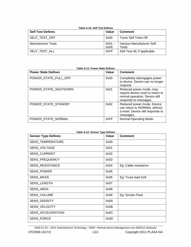
ANSI E1.20 – 2010, Entertainment Technology – RDM – Remote Device Management over DMX512 Networks
CP/2009-1017r2 -112- Copyright 2011 PLASA NA
Table A-10: Self Test Defines
Self Test Defines Value Comment
SELF_TEST_OFF 0x00 Turns Self Tests Off
Manufacturer Tests 0x01 – 0xFE
Various Manufacturer Self Tests
SELF_TEST_ALL 0xFF Self Test All, if applicable
Table A-11: Power State Defines
Power State Defines Value Comment
POWER_STATE_FULL_OFF 0x00 Completely disengages power to device. Device can no longer respond.
POWER_STATE_SHUTDOWN 0x01 Reduced power mode, may require device reset to return to normal operation. Device still responds to messages.
POWER_STATE_STANDBY 0x02 Reduced power mode. Device can return to NORMAL without a reset. Device still responds to messages.
POWER_STATE_NORMAL 0xFF Normal Operating Mode.
Table A-12: Sensor Type Defines
Sensor Type Defines Value Comment
SENS_TEMPERATURE 0x00
SENS_VOLTAGE 0x01
SENS_CURRENT 0x02
SENS_FREQUENCY 0x03
SENS_RESISTANCE 0x04 Eg: Cable resistance
SENS_POWER 0x05
SENS_MASS 0x06 Eg: Truss load Cell
SENS_LENGTH 0x07
SENS_AREA 0x08
SENS_VOLUME 0x09 Eg: Smoke Fluid
SENS_DENSITY 0x0A
SENS_VELOCITY 0x0B
SENS_ACCELERATION 0x0C
SENS_FORCE 0x0D

ANSI E1.20 – 2010, Entertainment Technology – RDM – Remote Device Management over DMX512 Networks
CP/2009-1017r2 -113- Copyright 2011 PLASA NA
SENS_ENERGY 0x0E
SENS_PRESSURE 0x0F
SENS_TIME 0x10
SENS_ANGLE 0x11
SENS_POSITION X 0x12 E.g.: Lamp position on Truss
SENS_POSITION Y 0x13
SENS_POSITION Z 0x14
SENS_ANGULAR_VELOCITY 0x15 E.g.: Wind speed
SENS_LUMINOUS_INTENSITY 0x16
SENS_LUMINOUS_FLUX 0x17
SENS_ILLUMINANCE 0x18
SENS_CHROMINANCE_RED 0x19
SENS_CHROMINANCE_GREEN 0x1A
SENS_CHROMINANCE_BLUE 0x1B
SENS_CONTACTS 0x1C E.g.: Switch inputs.
SENS_MEMORY 0x1D E.g.: ROM Size
SENS_ITEMS 0x1E E.g.: Scroller gel frames.
SENS_HUMIDITY 0x1F
SENS_COUNTER_16BIT 0x20
SENS_OTHER 0x7F
Manufacturer-Specific Sensors 0x80 – 0xFF

ANSI E1.20 – 2010, Entertainment Technology – RDM – Remote Device Management over DMX512 Networks
CP/2009-1017r2 -114- Copyright 2011 PLASA NA
Table A-13: Sensor Unit Defines
Sensor Unit Defines Value Table A-12 Reference
UNITS_NONE 0x00 CONTACTS
UNITS_CENTIGRADE 0x01 TEMPERATURE
UNITS_VOLTS_DC 0x02 VOLTAGE
UNITS_VOLTS_AC_PEAK 0x03 VOLTAGE
UNITS_VOLTS_AC_RMS 0x04 VOLTAGE
UNITS_AMPERE_DC 0x05 CURRENT
UNITS_AMPERE_AC_PEAK 0x06 CURRENT
UNITS_AMPERE_AC_RMS 0x07 CURRENT
UNITS_HERTZ 0x08 FREQUENCY / ANG_VEL
UNITS_OHM 0x09 RESISTANCE
UNITS_WATT 0x0A POWER
UNITS_KILOGRAM 0x0B MASS
UNITS_METERS 0x0C LENGTH / POSITION
UNITS_METERS_SQUARED 0x0D AREA
UNITS_METERS_CUBED 0x0E VOLUME
UNITS_KILOGRAMMES_PER_METER_CUBED 0x0F DENSITY
UNITS_METERS_PER_SECOND 0x10 VELOCITY
UNITS_METERS_PER_SECOND_SQUARED 0x11 ACCELERATION
UNITS_NEWTON 0x12 FORCE
UNITS_JOULE 0x13 ENERGY
UNITS_PASCAL 0x14 PRESSURE
UNITS_SECOND 0x15 TIME
UNITS_DEGREE 0x16 ANGLE
UNITS_STERADIAN 0x17 ANGLE
UNITS_CANDELA 0x18 LUMINOUS_INTENSITY
UNITS_LUMEN 0x19 LUMINOUS_FLUX
UNITS_LUX 0x1A ILLUMINANCE
UNITS_IRE 0x1B CHROMINANCE
UNITS_BYTE 0x1C MEMORY
Manufacturer-Specific Units 0x80 – 0xFF

ANSI E1.20 – 2010, Entertainment Technology – RDM – Remote Device Management over DMX512 Networks
CP/2009-1017r2 -115- Copyright 2011 PLASA NA
Table A-14: Sensor Unit Prefix Defines
Sensor Unit Prefix Defines Value Description
PREFIX_NONE 0x00 Multiply by 1
PREFIX_DECI 0x01 Multiply by 10-1
PREFIX_CENTI 0x02 Multiply by 10-2
PREFIX_MILLI 0x03 Multiply by 10-3
PREFIX_MICRO 0x04 Multiply by 10-6
PREFIX_NANO 0x05 Multiply by 10-9
PREFIX_PICO 0x06 Multiply by 10-12
PREFIX_FEMPTO 0x07 Multiply by 10-15
PREFIX_ATTO 0x08 Multiply by 10-18
PREFIX_ZEPTO 0x09 Multiply by 10-21
PREFIX_YOCTO 0x0A Multiply by 10-24
PREFIX_DECA 0x11 Multiply by 10+1
PREFIX_HECTO 0x12 Multiply by 10+2
PREFIX_KILO 0x13 Multiply by 10+3
PREFIX_MEGA 0x14 Multiply by 10+6
PREFIX_GIGA 0x15 Multiply by 10+9
PREFIX_TERRA 0x16 Multiply by 10+12
PREFIX_PETA 0x17 Multiply by 10+15
PREFIX_EXA 0x18 Multiply by 10+18
PREFIX_ZETTA 0x19 Multiply by 10+21
PREFIX_YOTTA 0x1A Multiply by 10+24
Notes:
When a prefix is used with MEMORY, the multiplier refers to binary multiple. i.e. KILO means multiply by 1024.
When a prefix is used with MASS, note that the UNIT is Kilogram. The prefix PREFIX_MILLI is used to denote grams.

ANSI E1.20 – 2010, Entertainment Technology – RDM – Remote Device Management over DMX512 Networks
CP/2009-1017r2 -116- Copyright 2011 PLASA NA
Table A-15: Data Type Defines
Data Type Defines Value Description
DS_NOT_DEFINED 0x00 Data type is not defined
DS_BIT_FIELD 0x01 Data is bit packed
DS_ASCII 0x02 Data is a string
DS_UNSIGNED_BYTE 0x03 Data is an array of unsigned bytes
DS_SIGNED_BYTE 0x04 Data is an array of signed bytes
DS_UNSIGNED_WORD 0x05 Data is an array of unsigned 16-bit words
DS_SIGNED_WORD 0x06 Data is an array of signed 16-bit words
DS_UNSIGNED_DWORD 0x07 Data is an array of unsigned 32-bit words
DS_SIGNED_DWORD 0x08 Data is an array of signed 32-bit words
Manufacturer-Specific Data Types
0x80 – 0xDF
Table A-16 Parameter Description Command Class Defines
Command Class Defines Value Description
CC_GET 0x01 PID supports GET only
CC_SET 0x02 PID supports SET only
CC_GET_SET 0x03 PID supports GET & SET

ANSI E1.20 – 2010, Entertainment Technology – RDM – Remote Device Management over DMX512 Networks
CP/2009-1017r2 -117- Copyright 2011 PLASA NA
Table A-17: Response NACK Reason Code Defines
Response NACK Reason Codes Value Description
NR_UNKNOWN_PID 0x0000 The responder cannot comply with request because the message is not implemented in responder.
NR_FORMAT_ERROR 0x0001 The responder cannot interpret request as controller data was not formatted correctly.
NR_HARDWARE_FAULT 0x0002 The responder cannot comply due to an internal hardware fault.
NR_PROXY_REJECT 0x0003 Proxy is not the RDM line master and cannot comply with message.
NR_WRITE_PROTECT 0x0004 SET Command normally allowed but being blocked currently.
NR_UNSUPPORTED_COMMAND_CLASS 0x0005 Not valid for Command Class attempted. May be used where GET allowed but SET is not supported.
NR_DATA_OUT_OF_RANGE 0x0006 Value for given Parameter out of allowable range or not supported.
NR_BUFFER_FULL 0x0007 Buffer or Queue space currently has no free space to store data.
NR_PACKET_SIZE_UNSUPPORTED 0x0008 Incoming message exceeds buffer capacity.
NR_SUB_DEVICE_OUT_OF_RANGE 0x0009 Sub-Device is out of range or unknown.
NR_PROXY_BUFFER_FULL 0x000A The proxy buffer is full and can not store any more Queued Message or Status Message responses.

ANSI E1.20 – 2010, Entertainment Technology – RDM – Remote Device Management over DMX512 Networks
CP/2009-1017r2 -118- Copyright 2011 PLASA NA
Appendix B: Status Message ID’s (Normative)
Manufacturers shall use publicly defined Status Message ID codes rather than developing their own Manufacturer-specific codes whenever possible.
Publicly defined codes are in the range of 0x0000 - 0x7FFF. Manufacturer-specific codes are in the range of 0x8000 – 0xFFDF.
Informative note: The ESTA website (http://www.esta.org/rdm) may document new publicly defined Status Message ID codes in addition to those enumerated in this document. Implementors of this standard are encouraged to check the ESTA website for applicable Status Message ID‘s before creating manufacturer-specific codes.
Table B-2 shows some of the predefined Status Message ID definitions, including the value, what the numeric value represents, and the recommended Status ID Description associated with the ID.
The Status ID Descriptions may include a marker that indicates how the controller should interpret the optional parameter value, and where the value should be displayed in the message displayed to the user. The marker types are defined in Table B-1.
Table B-1: Status Message Markers
Marker Description How to Display Parameter in User Message
%d Decimal Number as decimal number
%x Hexadecimal Number as hexadecimal number
%L Slot Label Code as text description of Slot Label Code
‗Slot Label Code‘ refers to the Slot ID in Table C-2
Table B-2: Status Message ID Definitions
Status Message ID Value Data Value 1 Data Value 2 Status ID Description
STS_CAL_FAIL 0x0001 Slot Label Code
―%L failed calibration‖
STS_SENS_NOT_FOUND 0x0002 Slot Label Code
―%L sensor not found‖
STS_SENS_ALWAYS_ON 0x0003 Slot Label Code
―%L sensor always on‖
STS_LAMP_DOUSED 0x0011 N/A ―Lamp doused‖
STS_LAMP_STRIKE 0x0012 N/A ―Lamp failed to strike‖
STS_OVERTEMP 0x0021 Sensor Number
Temperature ―Sensor %d over temp at %d degrees C‖
STS_UNDERTEMP 0x0022 Sensor Temperature ―Sensor %d under temp at %d degrees C‖
STS_SENS_OUT_RANGE 0x0023 Sensor Number
―Sensor %d out of range‖
STS_OVERVOLTAGE_ 0x0031 Phase Number Voltage ―Phase %d over voltage at

ANSI E1.20 – 2010, Entertainment Technology – RDM – Remote Device Management over DMX512 Networks
CP/2009-1017r2 -119- Copyright 2011 PLASA NA
PHASE %d V.‖
STS_UNDERVOLTAGE_
PHASE
0x0032 Phase Number Voltage ―Phase %d under voltage at %d V.‖
STS_OVERCURRENT 0x0033 Phase Number Current ―Phase %d over current at %d A.‖
STS_UNDERCURRENT 0x0034 Phase Number Current ―Phase %d under current at %d A.‖
STS_PHASE 0x0035 Phase Number Phase Angle ―Phase %d is at %d degrees‖
STS_PHASE_ERROR 0x0036 Phase Number ―Phase %d Error.‖
STS_AMPS 0x0037 Current ―%d Amps‖
STS_VOLTS 0x0038 Volts ―%d Volts‖
STS_DIMSLOT_OCCUPIED 0x0041 N/A ―No Dimmer‖
STS_BREAKER_TRIP 0x0042 N/A ―Tripped Breaker‖
STS_WATTS 0x0043 Wattage ―%d Watts‖
STS_DIM_FAILURE 0x0044 N/A ―Dimmer Failure‖
STS_DIM_PANIC 0x0045 N/A ―Panic Mode‖
STS_READY 0x0050 Slot Label Code
―%L ready‖
STS_NOT_READY 0x0051 Slot Label Code
―%L not ready‖
STS_LOW_FLUID 0x0052 Slot Label Code
―%L low fluid‖
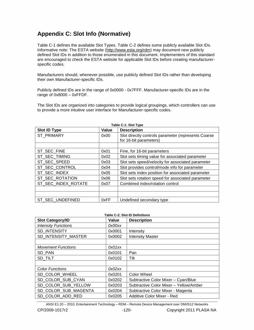
ANSI E1.20 – 2010, Entertainment Technology – RDM – Remote Device Management over DMX512 Networks
CP/2009-1017r2 -120- Copyright 2011 PLASA NA
Appendix C: Slot Info (Normative)
Table C-1 defines the available Slot Types. Table C-2 defines some publicly available Slot IDs. Informative note: The ESTA website (http://www.esta.org/rdm) may document new publicly defined Slot IDs in addition to those enumerated in this document. Implementers of this standard are encouraged to check the ESTA website for applicable Slot IDs before creating manufacturer-specific codes.
Manufacturers should, whenever possible, use publicly defined Slot IDs rather than developing their own Manufacturer-specific IDs.
Publicly defined IDs are in the range of 0x0000 - 0x7FFF. Manufacturer-specific IDs are in the range of 0x8000 – 0xFFDF.
The Slot IDs are organized into categories to provide logical groupings, which controllers can use to provide a more intuitive user interface for Manufacturer-specific codes.
Table C-1: Slot Type
Slot ID Type Value Description
ST_PRIMARY 0x00 Slot directly controls parameter (represents Coarse for 16-bit parameters)
ST_SEC_FINE 0x01 Fine, for 16-bit parameters
ST_SEC_TIMING 0x02 Slot sets timing value for associated parameter
ST_SEC_SPEED 0x03 Slot sets speed/velocity for associated parameter
ST_SEC_CONTROL 0x04 Slot provides control/mode info for parameter
ST_SEC_INDEX 0x05 Slot sets index position for associated parameter
ST_SEC_ROTATION 0x06 Slot sets rotation speed for associated parameter
ST_SEC_INDEX_ROTATE 0x07 Combined index/rotation control
ST_SEC_UNDEFINED 0xFF Undefined secondary type
Table C-2: Slot ID Definitions
Slot Category/ID Value Description
Intensity Functions 0x00xx
SD_INTENSITY 0x0001 Intensity
SD_INTENSITY_MASTER 0x0002 Intensity Master
Movement Functions 0x01xx
SD_PAN 0x0101 Pan
SD_TILT 0x0102 Tilt
Color Functions 0x02xx
SD_COLOR_WHEEL 0x0201 Color Wheel
SD_COLOR_SUB_CYAN 0x0202 Subtractive Color Mixer – Cyan/Blue
SD_COLOR_SUB_YELLOW 0x0203 Subtractive Color Mixer – Yellow/Amber
SD_COLOR_SUB_MAGENTA 0x0204 Subtractive Color Mixer - Magenta
SD_COLOR_ADD_RED 0x0205 Additive Color Mixer - Red

ANSI E1.20 – 2010, Entertainment Technology – RDM – Remote Device Management over DMX512 Networks
CP/2009-1017r2 -121- Copyright 2011 PLASA NA
SD_COLOR_ADD_GREEN 0x0206 Additive Color Mixer - Green
SD_COLOR_ADD_BLUE 0x0207 Additive Color Mixer - Blue
SD_COLOR_CORRECTION 0x0208 Color Temperature Correction
SD_COLOR_SCROLL 0x0209 Color Scroll
SD_COLOR_SEMAPHORE 0x0210 Color Semaphore
Image Functions 0x03xx
SD_STATIC_GOBO_WHEEL 0x0301 Static gobo wheel
SD_ROTO_GOBO_WHEEL 0x0302 Rotating gobo wheel
SD_PRISM_WHEEL 0x0303 Prism wheel
SD_EFFECTS_WHEEL 0x0304 Effects wheel
Beam Functions 0x04xx
SD_BEAM_SIZE_IRIS 0x0401 Beam size iris
SD_EDGE 0x0402 Edge/Lens focus
SD_FROST 0x0403 Frost/Diffusion
SD_STROBE 0x0404 Strobe/Shutter
SD_ZOOM 0x0405 Zoom lens
SD_FRAMING_SHUTTER 0x0406 Framing shutter
SD_SHUTTER_ROTATE 0x0407 Framing shutter rotation
SD_DOUSER 0x0408 Douser
SD_BARN_DOOR 0x0409 Barn Door
Control Functions 0x05xx
SD_LAMP_CONTROL 0x0501 Lamp control functions
SD_FIXTURE_CONTROL 0x0502 Fixture control channel
SD_FIXTURE_SPEED 0x0503 Overall speed setting applied to multiple or all parameters
SD_MACRO 0x0504 Macro control
SD_UNDEFINED 0xFFFF No definition

ANSI E1.20 – 2010, Entertainment Technology – RDM – Remote Device Management over DMX512 Networks
CP/2009-1017r2 -122- Copyright 2011 PLASA NA
Appendix D: Definitions (Normative) D.1 Acknowledge: a response to a request that indicates if the request was successful, and if
not, why the request failed.
D.2 Alternate START Code (ASC): a START Code with a non-zero value.
D.3 Binary search or binary tree search: a method of searching for a value in a range of values by continually halving or limiting the search range. A diagram of such a search resembles a tree.
D.4 Bidirectional Half Duplex: in a Bidirectional Half Duplex data link, requests flowing one direction and responses flowing the opposite direction are all carried over the same transmission media. This differs from a bidirectional full duplex data link in which requests flow over one transmission media, and responses flow over a second transmission media.
D.5 Bit Distortion: changes in bit timing due in part to unsymmetrical propagation delays and transition times. Bit distortion can be caused by both active electronics and passive circuit elements.
D.6 Bus Release: switching off a port transceiver's transmitter.
D.7 Byte: an unsigned, 8-bit value that can represent the numbers ranging from 0 to 255.
D.8 Checksum: an aid in verifying that data is successfully transmitted and received. In RDM communication, the checksum field is the unsigned, modulo 0x10000, 16-bit additive checksum of the entire packet‘s slot data, including START Code.
D.9 Collision or data collision: a data collision occurs when two or more devices attempt to transmit data at the same time on the same data link. The most likely outcome of this collision is that the data will become garbled. With the exception of the discovery process, RDM communication relies upon polling to avoid data collisions.
D.10 Controller: in any segment of an RDM communication system, only one device is free to initiate data transmissions. This device is termed a Controller.
D.11 Command port: a port from which RDM requests originate.
D.12 Controller Transmitter: the transmitter on a controller.
D.13 Data Delay: the time difference between the time data enters a circuit element and the time the data leaves the circuit element.
D.14 Data Link: the physical connection between transmitting and receiving devices.
D.15 Destination UID: the unique ID of the device to which a message is being sent.
D.16 Device: a piece of electrical or electronic equipment attached to an RDM communication system capable of transmitting, receiving and/or passing RDM messages.
D.17 Discovery: the process of finding RDM devices in an RDM communication system.
D.18 Driver Disable Time: the amount of time from the End of Packet to the time when the

ANSI E1.20 – 2010, Entertainment Technology – RDM – Remote Device Management over DMX512 Networks
CP/2009-1017r2 -123- Copyright 2011 PLASA NA
transmitter stops driving the data link.
D.19 Driver Enable Time: the amount of time from when a device begins driving the data link to the time when a device actually begins transmitting data onto the data link.
D.20 Duty Cycle: During a period of time, the fraction of time the signal is at a high level.
D.21 Encoded Unique ID (EUID): to help prevent data collisions during the Discovery process from being interpreted as NSC packets, device UID's are encoded in a fashion that insures there are no consecutive 0's in a device response. The result of this encoding is termed an Encoded Unique ID.
D.22 End of Packet (EOP): the end of the second stop bit of the last byte of the RDM packet. For the Unique Branch response packet this is the end of the second stop bit of the last byte of the EUID. For all other RDM packets, this is the end of the second stop bit of the last byte of the checksum.
D.23 Broadcast Device UID: a means of addressing a single message to a group of devices.
D.24 Gnd: an abbreviation for electrical ground, or the electrical power supply output from which other power supply outputs are measured or referenced.
D.25 In-line Devices: refers to devices that receives and re-transmits DMX512.
D.26 Inter-slot Delay: the amount of time between the end of one slot and beginning of the next slot in the packet.
D.27 Line Bias Network: the pull-up & pull-down circuits that create the marking bias when the RS485 line is not driven (all drivers are in high impedance mode).
D.28 Line Termination: the termination resistors located at both ends of a physical DMX512 link that are used to match the line impedance.
D.29 Manufacturer ID (MID): a two-byte value assigned to a Manufacturer/Organization by the E1 Accredited Standards Committee for use with specific Alternate START Codes. This ID identifies the data contained in the packet as proprietary. This packet may be safely ignored by systems that do not implement the specific start code.
D.30 Mark: a line condition where Data+ is high with respect to Data-. A Mark represents a binary 1.
D.31 Line Bias: a voltage potential impressed between Data+ and Data- when the data link is not driven (all drivers are in high impedance mode) that causes a Mark to be sensed by receiving devices.
D.32 Marking State: a Marking State exists when the voltage levels on the data+ and data- wires of the data link cause a logic 1 to be sensed by the various port receivers.

ANSI E1.20 – 2010, Entertainment Technology – RDM – Remote Device Management over DMX512 Networks
CP/2009-1017r2 -124- Copyright 2011 PLASA NA
D.33 Mute: during the discovery process, devices are located by asking them to respond if their UID is within the range of UID's contained in the Discovery Unique Branch message. Once a device has been found, the device is instructed to stop responding to the unique number queries. The Mute request is used to instruct the device to stop responding. A device that has been instructed to stop responding is said to be "muted". A device that is ―muted‖ only stops responding to the DISC_UNIQUE_BRANCH message and shall still respond to all other messages.
D.34 NULL START Code (NSC): a START Code with a value of zero (00h).
D.35 Packet: all the electrical transitions on the data link necessary to send a complete message is termed a Packet. In the context of RDM communications, a packet is comprised of a break, mark after break, message header, message data (if any), and checksum.
D.36 Parameter: a device attribute about which requests are sent and responses are made.
D.37 Polling: to prevent complete chaos on the data link, devices may only transmit data in response to a request from the controller. Polling is this process of request and response.
D.38 Port Turnaround: the switching of a port from the transmitting state to a receiving state, or from a receiving state to a transmitting state.
D.39 Proxy Device: any in-line device that acts as an agent or representative for one or more devices.
D.40 Responder Port: the port from which RDM responses originate.
D.41 Root Device: the top level device in a piece of equipment containing, either physically or logically, sub-devices. An example of a root device is the top level rack controller in a dimmer rack.
D.42 Segment: in its simplest form, a DMX512 network consists of a controller and controlled devices with no in-line devices. The insertion of in-line devices into the network divides the network into Segments.
D.43 Slot: a sequentially numbered, framed byte within the RDM packet.
D.44 Source UID: the unique ID of the device sending a message.
D.45 Space: a line condition where Data+ is low with respect to Data-. A Space represents a binary 0.
D.46 Splitter: A splitter is a device that receives a DMX/RDM data stream and replicates it on multiple command ports. RDM responses are replicated only on the responder port.
D.47 START Code: the first slot sent after the break indicating the type of information to follow.
D.48 Start of Packet (SOP): the leading edge of the BREAK at the beginning of an RDM packet. In the case of breakless responses (discovery), the SOP is defined as the leading edge of the start bit of the first slot sent by the responder.

ANSI E1.20 – 2010, Entertainment Technology – RDM – Remote Device Management over DMX512 Networks
CP/2009-1017r2 -125- Copyright 2011 PLASA NA
D.49 Sub-device: a device contained, either physically or logically, in another device. Individual sub-devices do not have UID's, but are referred to by using the root device's UID. A dimmer that is part of a dimmer rack is an example of a sub-device.
D.50 Sub-START Code: the second byte in the RDM packet. The sub-START Code is intended to allow future expansion of the START Code interface. Currently, the sub-START Code is assigned a default value.
D.51 Termination: components placed at the ends of a transmission line to match the impedance of the transmission line, preventing reflection of the data signals back into the transmission line that would degrade or destroy the transmitted signals.
D.52 Transaction Number: the Transaction Number is an unsigned 8-bit field. Controller generated packets increment this field every time a packet is transmitted. This field shall be initialized to 0 and roll over from 255 to 0. Responders echo the Transaction Number from the Controller Packet. Responders do not independently generate Transaction Numbers.
D.53 Unique ID (UID): a number used to uniquely identify a device.
D.54 Vcc: represents the power supply voltage used to power an electrical or electronic circuit.

ANSI E1.20 – 2010, Entertainment Technology – RDM – Remote Device Management over DMX512 Networks
CP/2009-1017r2 -126- Copyright 2011 PLASA NA
Appendix E: Discovery Pseudo-Code Example (Informative)
Find_Devices(0, 0x000000FFFFFFFFFFFE); // main call for device discovery process.
bool Find_Devices(long long LowerBound, long long UpperBound,)
long long MidPosition;
int DeviceFound;
if (LowerBound == UpperBound) // if we have called to the lowest branch and are testing
// for a single device.
do
Send DISC_MUTE Command to UID of device at ‗LowerBound‘.
while( no DISC_MUTE responses && <10 attempts);
if ( response received )
Add device found at ‗LowerBound‘ to list.
else
return( true );
else // look for a lower branch with active devices.
do
Send DISC_UNIQUE_BRANCH message.
while ( <3 attempts && no response)
if ( response received )
DeviceFound = true;
// check for single good response.
// !!! remove during FULL DEBUGGING VALIDATION begin
if ( response checksum passes ) // possibly only one device in branch.
// shortcut to avoid branching all the way down.
DeviceFound = Quick_Find( );
E.1 Find Devices Function Call
E.2 Find Devices Pseudo-Code
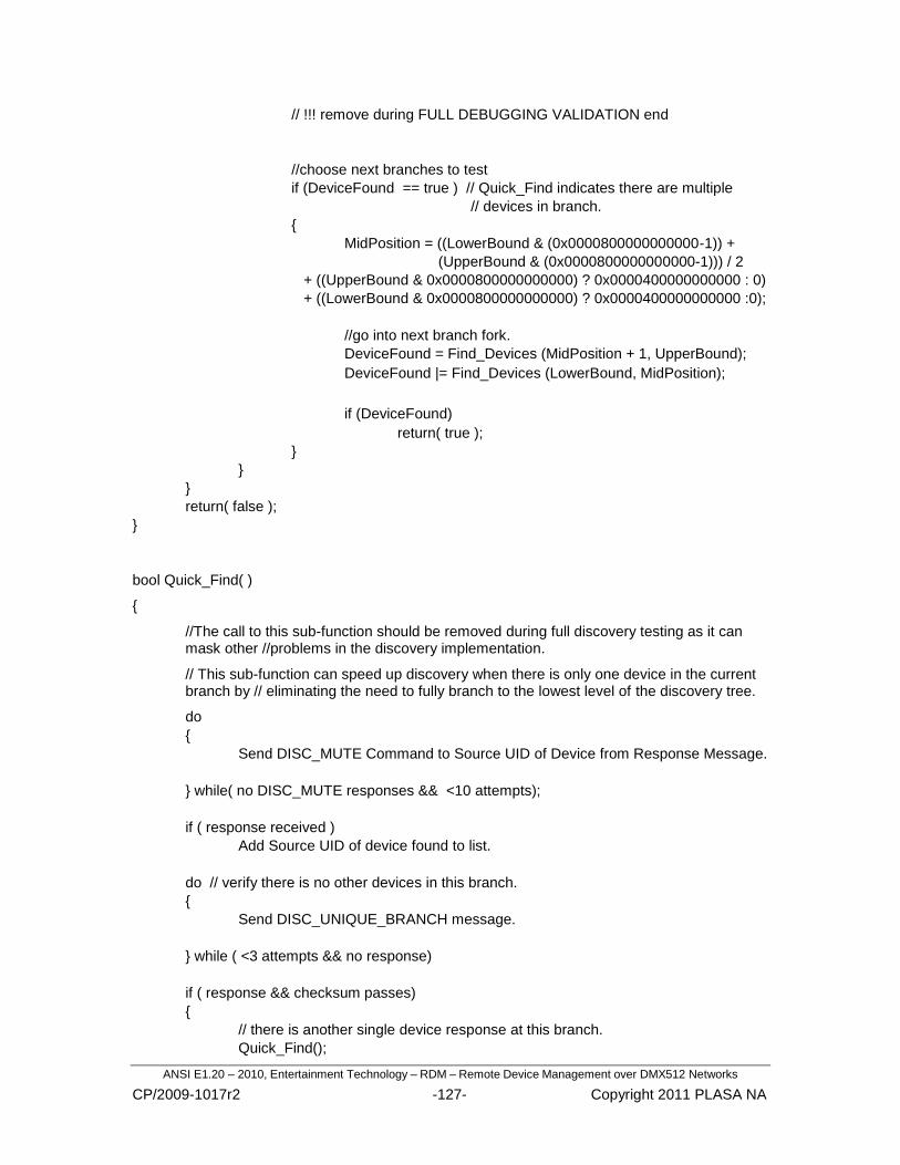
ANSI E1.20 – 2010, Entertainment Technology – RDM – Remote Device Management over DMX512 Networks
CP/2009-1017r2 -127- Copyright 2011 PLASA NA
// !!! remove during FULL DEBUGGING VALIDATION end
//choose next branches to test
if (DeviceFound == true ) // Quick_Find indicates there are multiple
// devices in branch.
MidPosition = ((LowerBound & (0x0000800000000000-1)) +
(UpperBound & (0x0000800000000000-1))) / 2
+ ((UpperBound & 0x0000800000000000) ? 0x0000400000000000 : 0)
+ ((LowerBound & 0x0000800000000000) ? 0x0000400000000000 :0);
//go into next branch fork.
DeviceFound = Find_Devices (MidPosition + 1, UpperBound); DeviceFound |= Find_Devices (LowerBound, MidPosition); if (DeviceFound)
return( true );
return( false );
bool Quick_Find( )
//The call to this sub-function should be removed during full discovery testing as it can mask other //problems in the discovery implementation.
// This sub-function can speed up discovery when there is only one device in the current branch by // eliminating the need to fully branch to the lowest level of the discovery tree.
do
Send DISC_MUTE Command to Source UID of Device from Response Message.
while( no DISC_MUTE responses && <10 attempts);
if ( response received )
Add Source UID of device found to list.
do // verify there is no other devices in this branch.
Send DISC_UNIQUE_BRANCH message.
while ( <3 attempts && no response)
if ( response && checksum passes)
// there is another single device response at this branch.
Quick_Find();

ANSI E1.20 – 2010, Entertainment Technology – RDM – Remote Device Management over DMX512 Networks
CP/2009-1017r2 -128- Copyright 2011 PLASA NA
else if ( response && failed checksum) // there are possibly multiple devices…
// branch further
return( true );
else // there is nothing left at this branch…move on.
return( false );

ANSI E1.20 – 2010, Entertainment Technology – RDM – Remote Device Management over DMX512 Networks
CP/2009-1017r2 -129- Copyright 2011 PLASA NA
Appendix F: Qualification tests for transmitter/receiver circuits used in RDM systems (Normative)
The combination of the line bias network of Section 2.5 and an EIA485 transmitter may present greater than a single unit load. The combination of the line biasing network and the transmitter design shall be tested for conformance with this standard and EIA485. The test circuits for command ports are given in Figure F-1 and Figure F-2.
Command port designs that pass these tests shall be considered capable of driving the command port load and 31 additional unit loads.
Responder port transmitters will also be affected by the line biasing network. These Responder ports are tested using the circuit shown in Figure F-4.
Figure F-1: Command Port Transmitter Test Circuit
F.1.1 Notes on Figure F-1
The Device Under Test (DUT) consists of the command port line driver, the line biasing network used in the design and any additional components used between the driver and the connection point. The DUT in Figure F-1 uses the reference line biasing network for illustration only.
The 1.8 volt reference (V1) and the variable reference (V2) (shown as batteries) shall be low impedance voltage sources capable of both sinking and sourcing current. The DUT shall be powered using the same voltage as the production circuit (V3). A method to switch the transmitter data input to either logic 1 or 0 shall be provided.(switch F/G). A method to disable (place in high impedance mode) or enable the transmitter is provided (Switch A/B). Resistors used to build the test load network shall be within 1% of stated values.
F.1 Qualification Tests for Command port Transmitter Circuits

ANSI E1.20 – 2010, Entertainment Technology – RDM – Remote Device Management over DMX512 Networks
CP/2009-1017r2 -130- Copyright 2011 PLASA NA
Tests for verifying transmitter circuits:
1) With the DUT transmitter disabled (placed in a high impedance state) the common mode voltage supply (V2) is varied from -7 VDC to +7 VDC. The bias voltage between TP1 and TP2 is observed and shall be greater than or equal to 245 mV for all allowed values of the common mode voltage.
2) With the DUT transmitter enabled the common mode supply is varied from -7 VDC to +7 VDC. The output between TP1 and TP2 is observed. The output shall have magnitude of greater than or equal to 1.5 VDC for all allowed values of common mode voltage and for either setting of switch F/G. It should be noted that 1.5 VDC is a minimum value; greater magnitudes are desirable.
3) Set the common mode supply to zero. The magnitude of the output between TP1 and TP2 shall vary less than 200 mV for either setting of switch F/G. The magnitude of the voltage difference between TP3 and TP4 shall be less than 200mV for either setting of switch F/G.
Figure F-2: Command Port Load Test Circuit
The following tests shall be used to determine that line biasing networks correctly load responder transmitters on the data link. This is achieved by comparison of the calibration circuit to the DUT.
The test circuit shown in Figure F-2 consists of an EIA485 transceiver (U1), with transmitter enabled, and powered by an appropriate supply (V3). The test circuit provides a means to switch the polarity of its output between mark and space. The test consists of two parts.
F.2 Output tests for testing transmitters / line bias networks for RDM command ports
F.3 Line loading tests for command ports

ANSI E1.20 – 2010, Entertainment Technology – RDM – Remote Device Management over DMX512 Networks
CP/2009-1017r2 -131- Copyright 2011 PLASA NA
Figure F-3: Calibration Circuit
Test1: Substitute the calibration circuit shown in Figure F-3 for the DUT. Set the supply for U2 (V4) and the line bias network to 5.5 volts. Set the output of U1 to Mark. Measure the voltage between TP1 and TP2, while adjusting the common mode supply (V2) between +7VDC and
-7VDC. Record the lowest magnitude measured.
Switch the output of U1 to space. While adjusting the common mode supply between +7VDC and -7VDC continue to measure the voltage between TP1 and TP2. Record the lowest magnitude measured.
Test2: Connect the DUT to the test circuit. Adjust the power supply (V4) to the high tolerance specified for the DUT. Set the output of U1 to Mark. Measure the voltage between TP1 and TP2, while adjusting the common mode supply between +7VDC and -7VDC. Record the lowest magnitude measured.
Switch the output of U1 to space. While adjusting the common mode supply between +7VDC and -7VDC continue to measure the voltage between TP1 and TP2. Record the lowest magnitude measured.
The DUT conforms to the requirements of clause F.3 of this standard if the lowest magnitude recorded for the DUT is greater than or equal to the lowest magnitude recorded for the calibration circuit.

ANSI E1.20 – 2010, Entertainment Technology – RDM – Remote Device Management over DMX512 Networks
CP/2009-1017r2 -132- Copyright 2011 PLASA NA
The DUT shown in Figure F-4 consists of the responder line driver and any additional components used between the driver and the connection point.
Figure F-4: Responder Test Circuit
The 1.8 volt reference (V1) and the variable reference (V2) (shown as batteries) shall be low impedance voltage sources capable of both sinking and sourcing current. The power supply for the test load (G) shall be 5 volts DC. A method to switch the transmitter data input to either logic 1 or 0 shall be provided (switch F/G). A method to either disable (place in a high impedance state) or enable the transmitter is provided (Switch A/B). Resistors used to build the test load network shall be within 1% of stated values. V4 shall be set to equal the supply voltage that will run the DUT in production.
With the DUT transmitter enabled, and with either setting of switch E/F, the common mode supply (V2) is varied between -7 VDC and +7 VDC. The output magnitude shall be greater than or equal to 1.5 VDC for all values of common mode voltage.
Set the common mode supply (V2) to zero. The magnitude of the output between TP1 and TP2 shall vary less than 200 mV for either setting of switch F/G. The magnitude of the voltage difference between TP3 and TP4 shall be less 200mV for either setting of switch F/G.
Responder port designs that pass these tests shall be considered capable of driving the command port load and 31 additional unit loads.
F.4 Notes on the responder test circuit
F.5 Testing Responder Transmitters

ANSI E1.20 – 2010, Entertainment Technology – RDM – Remote Device Management over DMX512 Networks
CP/2009-1017r2 -133- Copyright 2011 PLASA NA
Contact Information
Karl G. Ruling
Technical Standards Manager
PLASA
630 Ninth Avenue, Suite 609
New York, NY 10036
USA
Phone: 1-212-244-1505
Fax: 1-212-244-1502
Technical Standards Council Chairperson
Mr. Mike Garl
President
James Thomas Engineering, Inc.
10240 Caneel Drive
Knoxville, TN 37931
USA
Phone: 1-865-692-3060
FAX: 1-865-692-9020
Control Protocols Working Group Chairpersons
Michael Lay Philips Color Kinetics
3 Burlington Woods Drive
Burlington, MA 01803 USA
Phone: 1-781-418-9145 [email protected]
Kimberly Corbett Schuler Shook. 325 North Saint Paul, Suite 3250
Dallas, TX 75201
USA
Phone: 1-214-747-8300 [email protected]

ANSI E1.20 – 2010, Entertainment Technology – RDM – Remote Device Management over DMX512 Networks
CP/2009-1017r2 -134- Copyright 2011 PLASA NA
Acknowledgments: The task group for writing this document in its original 2006 and revised 2010 editions was:
Project leader: Scott M. Blair, Barco (USA) 2006/2010
Javid Butler, Integrated Theatre (USA) 2006
Ben Darrington, Wireless Solutions (Sweden) 2010
Milton Davis, Doug Fleenor Design (USA) 2006/2010
Gary Douglas, Pathway Connectivity (Canada) 2006
Hammish Dumbreck, JESE (UK) 2010
Doug Fleenor, Doug Fleenor Design (USA) 2006/2010
Bob Goddard, Goddard Design (USA) 2006/2010
Tom Grimes, High End Systems (USA) 2006
Wayne Howell, Artistic Licence (UK) 2006
Eric Johnson, Barco (USA) 2010
Michael Karlsson, LumenRadio (Sweden) 2010
Paul Kleissler, City Theatrical (USA) 2010
Kevin Loewen, Pathway Connectivity (Canada) 2006/2010
Paul McMaster, Cooper Controls/Zero88 (UK) 2010
Simon Newton (USA) 2010
Jason Potterf, High End Systems (USA) 2006
Charles Reese, Production Resource Group (USA) 2006/2010
Michael A. (Sandy) Twose, Sand Network Systems (Canada) 2006
Tracy Underhill, Electronics Diversified Inc. (USA) 2006/2010
Peter Willis, Howard Eaton Lighting Ltd. (UK) 2006/2010
The Control Protocols Working Group voting members at the time this document was approved by the working group on 29 July 2010 are shown below. The company or organization listed is the company or organization represented. Voting status is shown by P for principal and A for alternate. The interest category follows the voting status.
Daniel W. Antonuk; Electronic Theatre Controls, Inc.; P; MP
Robert Armstrong; Pathway Connectivity Inc.; A; MP
Robert Bell; Horizon Control Inc.; A; MP
Marcus Bengtsson; LumenRadio AB; A; MP
Scott M. Blair; Barco; P; MP
Ron Bonner; PLASA; P; G
Kimberly Corbett; Schuler Shook; P; DE
Stuart Cotts; Oregon Shakespeare Festival; P; U
Milton Davis; Doug Fleenor Design, Inc.; A; MP
Gary Douglas; Horizon Control Inc.; A; MP
Larry Dunn; City Theatrical, Inc.; A; MP
Doug Fleenor; Doug Fleenor Design, Inc.; P; MP
Ed Garstkiewicz; Harting KGAA; A; G
Robert Goddard; Goddard Design Co.; P; MP
Tom Grimes; Barco; A; MP
Dennis Grow; I.A.T.S.E. Local 728; A; U
Mitch Hefter; USITT; P; U
Dave Higgins; Pathway Connectivity Inc.; A; MP
John Huntington; I.A.T.S.E. Local 1; A; U
Michael Karlsson; LumenRadio AB; P; MP

ANSI E1.20 – 2010, Entertainment Technology – RDM – Remote Device Management over DMX512 Networks
CP/2009-1017r2 -135- Copyright 2011 PLASA NA
Peter Kirkup; Cooper Controls Ltd.; P; MP
Paul Kleissler; City Theatrical, Inc.; P; MP
Edwin S. Kramer; I.A.T.S.E. Local 1; P; U
Ulrich Kunkel; DIN, NVBF Committee; P; U
Roger Lattin; I.A.T.S.E. Local 728; P; U
Hans Lau; Sand Network Systems, Inc.; P; MP
Michael Lay; Royal Philips Electronics; P; MP
Kevin Loewen; Pathway Connectivity Inc.; P; MP
Alan Martello; Horizon Control Inc.; P; MP
Tyrone Mellon Jr.; Lex Products Corp.; P; CP
Philip Nye; Engineering Arts; P; G
Edward A. (Ted) Paget; Daktronics Inc.; P; G
Charles Reese; Production Resource Group; P; DR
Alan M. Rowe; I.A.T.S.E. Local 728; A; U
Yngve Sandboe; Sand Network Systems, Inc.; A; MP
Steve Terry; Electronic Theatre Controls, Inc.; A; MP
Robert Tooker; Production Resource Group; A; DR
Ken Vannice; Leviton Manufacturing Co., Inc.; P; MP
Jody Williquette; Harting KGAA; P; G
David Yellin; LightMinded Industries, Inc.; P; MP
Observer (non-voting) members:
Simon Alpert; Lighttech Event Technologies; CP
Klaus Amling; Licht-Technik; MP
Shahid Anwar; Avolites Ltd.; MP
Tim Bachman; A.C.T Lighting, Inc.; DR
RobertBarbagallo; Solotech Inc.; U
William Benner; Pangolin Laser Systems; MP
Adam Bennette; Electronic Theatre Controls Ltd.; MP
David Bertenshaw; David Bertenshaw; G
Stephen Bickford; T. Kondos Associates; U
Torrey Bievenour; Vision Quest Lighting; G
Mike Blackwell; Philips/Color Kinetics ; MP
Lee J. Bloch; Bloch Design Group, Inc.; G
David A. Boller; Organic Machines LLC; CP
André Broucke; G
Larry Busch; ADB Lighting Technologies; MP
John (Javid) D. Butler; Integrated Theatre, Inc.; CP
Steve Carlson; High Speed Design, Inc.; MP
Nyasha Chigwamba; Dept. of Computer Science, Rhodes University; U
Soo-Myong Chung; Bloch Design Group, Inc.; G
Paul J. Clark; HxDx; CP
Edward R. Condit; G
Eric Cornwell; West Side Systems; U
Klas Dalbjorn; Labgruppen AB; MP
Ben Darrington; Wireless Solutions Sweden AB; MP
Gary Dove; Dove Systems; MP
Hamish Dumbreck; JESE Ltd.; MP
Jerry Durand; Durand Interstellar, Inc.; CP

ANSI E1.20 – 2010, Entertainment Technology – RDM – Remote Device Management over DMX512 Networks
CP/2009-1017r2 -136- Copyright 2011 PLASA NA
James Eade; PLASA; G
Andrew Eales; Wellington Institute of Technology, Rhodes University; U
Joost van Eenbergen; ELC Lighting; MP
Bill Ellis; Candela Controls, Inc.; U
Paul K. Ericson; Syska Hennessy Group Lighting Design; U
Jon R. Farley; Sixteenth Avenue Systems; CP
Martin Farnik; Robe Show Lighting s.r.o.; MP
Trevor Forrest; Helvar Lighting Control; MP
Douglas Franz; QVC Network; U
Steve Friedlander; Auerbach Pollock Friedlander; U
Phillip M. Gallo; TMB; DR
Jerry Gorrell; Theatre Safety Programs; G
Josh Gubler; CP
Rob Halliday; U
Sean Harding; Trinity Repertory Company; U
Bill Hewlett; Hewlett Electronics; CP
Simon Hobday; Artistic Licence (UK) Ltd.; CP
Helge Hoffmann; JB Lighting; MP
Jim Holladay; Luxence; G
Wayne David Howell; Artistic Licence (UK) Ltd.; CP
Osedum P. Igumbor; Dept. of Computer Science, Rhodes University; U
Sierk Janszen; Kiss Box; U
Eric Johnson; MP
Rob Johnston; Interactive Technologies, Inc.; MP
Ed Jones; Edwin Jones Co., Inc.; CP
Torben Kaas Rasmussen; Martin Professional A/S; G
Jussi Kallioinen; Eastway Sound & Lighting; U
Ujjal Kar; Standard Robotics & Lighting; G
Kirk D. Keen; Hollywood Lighting Services, Inc.; DR
Paul Kenneth McEwan; Zero 88; MP
Hiroshi Kita; Marumo Electric Co., Ltd.; MP
Mark T. Kraft; Lehigh Electric Products Co.; MP
Rick Leinen; Leviton Manufacturing Co., Inc.; MP
Hans Leiter; ETC GmbH; MP
Jon Lenard; Applied Electronics; MP
Mark Manthei; Shure Inc.; G
Paul F. Mardon; Pulsar Ltd.; MP
Mick Martin; ShowCAD Control Systems; MP
John Mehltretter; Lehigh Electric Products Co.; MP
Avraham Mendall Mor "Avi"; Lightswitch; U
Tobin Neis; Barbizon Companies; DR
Lars F. Paape; Scientific Algorithms and Embedded Systems; U
Fabiano Pina; Clay Paky S.P.A.; MP
Gary Pritchard; LSC Lighting Systems (Aust) PTY Ltd; MP
Eric Proces; U
Charlie Richmond; Richmond Sound Design Ltd.; CP
Bernardo Benito Rico; Ben-Ri Electronica S.A.; MP
Steve Roberts; Carr & Angier; G
Erwin Rol; Erwin Rol Software Engineering; G
Dietmar Rottinghaus; Connex GmbH; G
Richard Salzedo; Avolites Ltd.; MP

ANSI E1.20 – 2010, Entertainment Technology – RDM – Remote Device Management over DMX512 Networks
CP/2009-1017r2 -137- Copyright 2011 PLASA NA
Larry Schoeneman; DesignLab Chicago, Inc.; DR
Chuck Seifried; Phoenix Civic Plaza; U
John Sellers; AIM Northwest; G
Andrew Sherar; Lightmoves PLC; MP
Yehuda Shukram; Compulite Systems; MP
John Sondericker_III; Wybron, Inc.; MP
Storm K. Staley; Stormwerx; U
Bart Swinnen; Luminex LCE; MP
Arnold Tang; Arnold Tang Productions; U
Geoffrey O. Thompson; Nortel Networks, Inc.; G
David Timmins; Jands Electronics; MP
J. B. Toby; Avolites Ltd.; MP
Bob Toms; Catalyst Microsystems LLC; G
Tad Trylski; U
Stephen J. Tyrrell; Quantum Logic; MP
Tracy Underhill; 4U Consulting; G
Steve Unwin; Pulsar Ltd.; MP
Dominic Vincenty; Television Production Service; DR
Will Wagner; Carallon Ltd.; MP
John Warwick; Philips Color Kinetics ; MP
Colin Waters; TMB; DR
Ralph Weber; ENDL Texas; G
Lars Wernlund; Lewlight; MP
Michael (Mike) Whetstone; Integrated Theatre, Inc.; CP
Loren Wilton; Showman Systems; CP
Barbara Wohlsen; U
Jiantong Wu; Beijing Special Engineering Design & Research Institute; G
Kehang Wu; Shure Inc.; G
David Yellin; LightMinded Industries, Inc.; MP
Larry Zoll; Zoll Design & Consulting, LLC; U
Interest category codes:
CP = custom-market producer
DE = designer
DR = dealer rental company
G = general interest
MP = mass-market producer
U = user


![RDM [module] RDM-[module]-1… · medium rdm-[module]-15 aheeehapkfgloppjljhoekmmlaanogfkbpaheeeha bnfffnbpepadepelacadbhecbkjpbhfgnpbnfffnb jaibeeflfohfjhjkaphgbjahblpaggncggelagnep](https://static.fdocuments.in/doc/165x107/5fa322a37cebb95cfe55ebc7/rdm-module-rdm-module-1-medium-rdm-module-15-aheeehapkfgloppjljhoekmmlaanogfkbpaheeeha.jpg)