ANS’04 International Summer School on Selected Topics in Analog IC Design, Cracow, 13-18 September...
205
ANS’04 International Summer School on Selected Topics in Analog IC Design, Cracow, 13-18 September 2004 Supported by the REASON IST-2000-30193 project of the EU Electro-Thermal Simulation By A. Poppe, BUTE, Electro-thermal simulation Methods, tools, examples András Poppe [email protected] BUTE, Department of Electron Devices by:
-
date post
18-Dec-2015 -
Category
Documents
-
view
213 -
download
0
Transcript of ANS’04 International Summer School on Selected Topics in Analog IC Design, Cracow, 13-18 September...

ANS’04 International Summer School on Selected Topics in Analog IC Design,
Cracow, 13-18 September 2004 Supported by the REASON IST-2000-30193 project of the EU
Electro-Thermal Simulation
By A. Poppe, BUTE, Hungary
Electro-thermal simulationMethods, tools, examples
András [email protected]
BUTE, Department of Electron Devices
by:

ANS’04 International Summer School on Selected Topics in Analog IC Design,
Cracow, 13-18 September 2004 Supported by the REASON IST-2000-30193 project of the EU
Electro-Thermal Simulation
By A. Poppe, BUTE, Hungary
Heat, like gravity, penetrates every substance of the universe;
its rays occupy all parts of space. The theory of heatwill hereafter form one of the most important
branches of general physics.
Joseph Fourier, 1824

ANS’04 International Summer School on Selected Topics in Analog IC Design,
Cracow, 13-18 September 2004 Supported by the REASON IST-2000-30193 project of the EU
Electro-Thermal Simulation
By A. Poppe, BUTE, Hungary
Outline• GENERAL INTRODUCTION
– role of circuit simulation– electro-thermal simulation– simulation methods
• SIMULTANEOUS SIMULATION– operation of a circuit simulator
• structure of a simulator• the nodal solution method• generating the equations to be solved
– linear DC - admittance matrix– non-linear DC - the Jacobian matrix
• device models– electro-thermal device models– thermal model of the chip
• BREAK

ANS’04 International Summer School on Selected Topics in Analog IC Design,
Cracow, 13-18 September 2004 Supported by the REASON IST-2000-30193 project of the EU
Electro-Thermal Simulation
By A. Poppe, BUTE, Hungary
Outline (cont.)• THERMAL MODELING for simultaneous electro-thermal
simulation– 3D RC model of the chip– Example for an electro-thermal simulation system using 3D RC
circuit model• CHARACTERIZATION AND COMPACT MODELING OF
THERMAL SYSTEMS– What is compact?– Steady-state model, dynamic model– The unit-step response & time-constant spectrum concept– Convolution calculus, network models– Fast calculation & modeling method
• BREAK

ANS’04 International Summer School on Selected Topics in Analog IC Design,
Cracow, 13-18 September 2004 Supported by the REASON IST-2000-30193 project of the EU
Electro-Thermal Simulation
By A. Poppe, BUTE, Hungary
Outline (cont.)• IMPLEMENTATION EXAMPLE of simultaneous electro-
thermal simulation: SISSI (BUTE) – Introduction, design flows– History of implementations, snapshots of operation– Future extension
• SIMULATION EXAMPLES WITH SISSI– Typical examples highlighting the importance of electro-thermal
simulation• OTA, micro hot-plate, layout/packaging dependent OpAmp behavior
– Experimental validation • Early program version integrated into Cadence Opus ECPD10 design kit• Reverse engineered A741 variants simulated with the recent solver &
measured• Study of micromachined RMS meter
• OUTLOOK, SUMMARY, LITERATURE– Logi-thermal simulation
• THE END

ANS’04 International Summer School on Selected Topics in Analog IC Design,
Cracow, 13-18 September 2004 Supported by the REASON IST-2000-30193 project of the EU
Electro-Thermal Simulation
By A. Poppe, BUTE, Hungary
GENERAL INTRODUCTION:role of circuit simulationelectro-thermal simulationsimulation methods

ANS’04 International Summer School on Selected Topics in Analog IC Design,
Cracow, 13-18 September 2004 Supported by the REASON IST-2000-30193 project of the EU
Electro-Thermal Simulation
By A. Poppe, BUTE, Hungary Optimization
Physical device simulation Process simulation
Device parameters Design rules
Behavioral description
Specification in VHDL or in Verilog
System simulatorSystem level design
Structural description Schematic editorLogic simulation
Synthesis
Logic level design
Layout generation
Layout description Layout editorCircuit simulator
Timing parameters
Transistor level design
Abstraction levelRepresentation:Simulator:
CAD tools in VLSI design
Process and device design: TCAD tools used in silicon foundries. Ordinary designers do not use such tools.

ANS’04 International Summer School on Selected Topics in Analog IC Design,
Cracow, 13-18 September 2004 Supported by the REASON IST-2000-30193 project of the EU
Electro-Thermal Simulation
By A. Poppe, BUTE, Hungary Optimization
Physical device simulation Process simulation
Device parameters Design rules
Behavioral description
Specification in VHDL or in Verilog
System simulatorSystem level design
Structural description Schematic editorLogic simulation
Synthesis
Logic level design
Layout generation
Layout description Layout editorCircuit simulator
Transistor level design
Abstraction levelRepresentation:Simulator:
Details of actual realization are hidden from most of the designers
CAD tools in VLSI design

ANS’04 International Summer School on Selected Topics in Analog IC Design,
Cracow, 13-18 September 2004 Supported by the REASON IST-2000-30193 project of the EU
Electro-Thermal Simulation
By A. Poppe, BUTE, Hungary Optimization
Physical device simulation Process simulation
Device parameters Design rules
Behavioral description
Specification in VHDL or in Verilog
System simulatorSystem level design
Structural description Schematic editorLogic simulation
Synthesis
Logic level design
Layout generation
Layout description Layout editorCircuit simulator
Timing parameters
Transistor level design
Abstraction levelRepresentation:Simulator:
The role of circuit simulation

ANS’04 International Summer School on Selected Topics in Analog IC Design,
Cracow, 13-18 September 2004 Supported by the REASON IST-2000-30193 project of the EU
Electro-Thermal Simulation
By A. Poppe, BUTE, Hungary
When design is done on transistor level circuit simulation
is a verification tool.
That is in case of– design of standard cells,– analog circuit design,
i.e. in all cases when the circuit is designed in form of – transistor level schematic, or– “manual” layout (or both).
The role of circuit simulation

ANS’04 International Summer School on Selected Topics in Analog IC Design,
Cracow, 13-18 September 2004 Supported by the REASON IST-2000-30193 project of the EU
Electro-Thermal Simulation
By A. Poppe, BUTE, Hungary
The role of circuit simulation
• In case of digital design:We do not meet it, since the designer does not need circuit simulation on these abstraction levels (system design, logic level design).
• Design of standard cells:A cell is designed on transistor level, thus circuit simulation is needed.
• Analog designis performed on transistor level, an important tool of verification is always a circuit simulator:
• Pre-layout verification • Post-layout verification

ANS’04 International Summer School on Selected Topics in Analog IC Design,
Cracow, 13-18 September 2004 Supported by the REASON IST-2000-30193 project of the EU
Electro-Thermal Simulation
By A. Poppe, BUTE, Hungary
The role of circuit simulation
Transistor level schematic
Schematic editor
Circuit simulator
netlist
Pre-layout simulation: functional verification

ANS’04 International Summer School on Selected Topics in Analog IC Design,
Cracow, 13-18 September 2004 Supported by the REASON IST-2000-30193 project of the EU
Electro-Thermal Simulation
By A. Poppe, BUTE, Hungary
Layout synthesis
Layout Layout editorLayout extraction
netlist
Circuit simulator Post-layout simulation: verification of the realization
The role of circuit simulation
Transistor level schematic
Schematic editor
Circuit simulator
netlist
Pre-layout simulation: functional verification

ANS’04 International Summer School on Selected Topics in Analog IC Design,
Cracow, 13-18 September 2004 Supported by the REASON IST-2000-30193 project of the EU
Electro-Thermal Simulation
By A. Poppe, BUTE, Hungary
Schematic editor
Other tools of verification
LVS: layout vs. schematic
Layout
DRC: design rule check
Transistor level schematic

ANS’04 International Summer School on Selected Topics in Analog IC Design,
Cracow, 13-18 September 2004 Supported by the REASON IST-2000-30193 project of the EU
Electro-Thermal Simulation
By A. Poppe, BUTE, Hungary
But…
Still, lots of details of physical realization or effects during circuit operation are not considered in this design flow:
• the chip itself (e.g. bulk MOS or SOI)• the effect of the packaging (die attach, bonding, the leads)• etc.
The chip itself and the packaging play important role in
• high frequency behavior• thermal behavior

ANS’04 International Summer School on Selected Topics in Analog IC Design,
Cracow, 13-18 September 2004 Supported by the REASON IST-2000-30193 project of the EU
Electro-Thermal Simulation
By A. Poppe, BUTE, Hungary
Electro-thermal simulation

ANS’04 International Summer School on Selected Topics in Analog IC Design,
Cracow, 13-18 September 2004 Supported by the REASON IST-2000-30193 project of the EU
Electro-Thermal Simulation
By A. Poppe, BUTE, Hungary
Electro-thermal simulation
• Besides electrical behavior thermal behavior is considered
• All semiconductor devices– are sensitive to temperature– dissipate heat (self-heating)– There is a thermal drift of device and circuit parameters due to
• self heating and• heating of other dissipators on the chip
• The electrical and thermal behavior of the chip needs to be simulated in a self-consistent manner
• Electro-thermal simulation might be needed even in case of digital circuits
IF = I0 [exp(UF/Ut)-1]

ANS’04 International Summer School on Selected Topics in Analog IC Design,
Cracow, 13-18 September 2004 Supported by the REASON IST-2000-30193 project of the EU
Electro-Thermal Simulation
By A. Poppe, BUTE, Hungary
Thermal behavior of a diode
IFUF
UF
IF
IF ΔUF
Cool device
Hot device
UF = Ut ln(IF/I0) → ΔUF / ΔT 2mV/oCIF = I0 [exp(UF/Ut)-1] I0 exp(UF/Ut)
Temperature dependence of device parameters:
Dissipation:
PD = IF UF Self-heating:
Tj = PD Rthja
How to obtain?

ANS’04 International Summer School on Selected Topics in Analog IC Design,
Cracow, 13-18 September 2004 Supported by the REASON IST-2000-30193 project of the EU
Electro-Thermal Simulation
By A. Poppe, BUTE, Hungary
The core of the problem:
• The electrical behavior of semiconductor devices is well described by compact (lumped) models
The semiconductor equations (PDE-s) are replaced by analytical models (lumped/compact) – these are the device characteristics:
• Thermal behavior is described by the differential equation of heat transfer – description is on physical levelTgradp
ngradqDEnqJ nnn
pgradqDEpqJ ppp
1/exp0 Tid UUII
dp
p
an
ni NL
D
NL
DnAqI 2
0
kT
WTconstn F
i exp32
• Two different abstraction levels have to be treated

ANS’04 International Summer School on Selected Topics in Analog IC Design,
Cracow, 13-18 September 2004 Supported by the REASON IST-2000-30193 project of the EU
Electro-Thermal Simulation
By A. Poppe, BUTE, Hungary
Simulation methods

ANS’04 International Summer School on Selected Topics in Analog IC Design,
Cracow, 13-18 September 2004 Supported by the REASON IST-2000-30193 project of the EU
Electro-Thermal Simulation
By A. Poppe, BUTE, Hungary
Possible simulation methods• Neglect thermal effects – that is the practice now in most
cases: – problems remain hidden
• Physical level simulation– OK for a single device
but can not be used in VLSI design
• Simulator coupling:– Circuit simulator that calculates dissipation values and
semiconductor model parameters can be recalculated for any temperature
– Thermal simulator to provide temperature distribution from the dissipation data

ANS’04 International Summer School on Selected Topics in Analog IC Design,
Cracow, 13-18 September 2004 Supported by the REASON IST-2000-30193 project of the EU
Electro-Thermal Simulation
By A. Poppe, BUTE, Hungary
Possible simulation methods• Simulator coupling:
– Problems:• Double iteration
– Inside a simulator– Between the simulators
• Can not treat circuits with strong thermal coupling• Dynamic electro-thermal behavior (ac, transient) improperly treated
• Simultaneous solution (direct method, fully coupled)– Difficult to implement
• El.-th. device models?• Efficient thermal model?
– Gives correct solutions• For thermal feed-back,• Strong couplings• Dynamic behavior
SPICE ANSYS
TRANS-TRAN

ANS’04 International Summer School on Selected Topics in Analog IC Design,
Cracow, 13-18 September 2004 Supported by the REASON IST-2000-30193 project of the EU
Electro-Thermal Simulation
By A. Poppe, BUTE, Hungary
Electro-thermal simulation – physical level
• Let us consider the flow of carriers in a piece of n-type semiconductor
Let us substitute:
kT
Wnn Fexp0 and F
F WgradkT
Wn
kTngrad
exp
10
Furthermore: UgradE
q
kTD
n
n and
U
q
WgradnqJ F
nn
With these substitutions we end up with:
ngradqDEnqJ nnn
or
n
ngradDEnqJ
n
nnn
General driving force of carriers
Let us further substitute: Uq
WU F ' and '' UgradE
and nq ne
'UgradJ en
Differential Ohm’s law

ANS’04 International Summer School on Selected Topics in Analog IC Design,
Cracow, 13-18 September 2004 Supported by the REASON IST-2000-30193 project of the EU
Electro-Thermal Simulation
By A. Poppe, BUTE, Hungary
Electro-thermal simulation – physical level
• Let us consider the heat-flow
'UgradJ en Heat-flow equation analogous to the
differential Ohm’s law
Tgradp
current density – heat flux
electrical conductivity – thermal conductivity
potential – temperature
• Coupled flow of charge carriers and energy:
TgradSEJ een '
TgradTSETSp ee 2'
S – Seebeck coefficient
Electro-thermal cross terms accounting for Seebeck- & Peltier-effect.

ANS’04 International Summer School on Selected Topics in Analog IC Design,
Cracow, 13-18 September 2004 Supported by the REASON IST-2000-30193 project of the EU
Electro-Thermal Simulation
By A. Poppe, BUTE, Hungary
Electro-thermal simulation – physical level• Seebeck-effect: Let us assume 0nJ
TgradSEJ een '
TgradSE ee '
TgradSE '
After integrating both sides: )( 21 TTSU Thermo potential:proportional to the temperature difference of two locations
TgradTSETSp ee 2'
TgradSEJ een '
• Peltier-effect: Let us assume 0Tgrad'EJ en
'ETSp e
e
nJE
'
JTSp
Electrically pumped heat-flow
Might be important in analog IC/MEMS design
Neglected in analog IC design

ANS’04 International Summer School on Selected Topics in Analog IC Design,
Cracow, 13-18 September 2004 Supported by the REASON IST-2000-30193 project of the EU
Electro-Thermal Simulation
By A. Poppe, BUTE, Hungary
Electro-thermal simulation – physical level• Tools solving the joint system of partial differential
equations (plus Poission’s eq.)
are called physical device simulators.
TgradTSETSp ee 2'
TgradSEJ een '
• They are suitable for single devices (such as power semiconductors) but can not be used in analog IC design where there are multiples of semiconductors.(execution times, amount of data, difficult problem input)

ANS’04 International Summer School on Selected Topics in Analog IC Design,
Cracow, 13-18 September 2004 Supported by the REASON IST-2000-30193 project of the EU
Electro-Thermal Simulation
By A. Poppe, BUTE, Hungary
SIMULTANEOUS SIMULATION:operation of a circuit simulatorelectro-thermal device modelsthermal model of the chip

ANS’04 International Summer School on Selected Topics in Analog IC Design,
Cracow, 13-18 September 2004 Supported by the REASON IST-2000-30193 project of the EU
Electro-Thermal Simulation
By A. Poppe, BUTE, Hungary
Simultaneous simulation
• Simultaneous simulation is a method that allows fast and accurate electro-thermal CIRCUIT simulation
• Requirements:– Circuit simulation engine with
electro-thermal device models
– Method of generating electrical model of the thermal system, suitable for circuit simulation
– Efficient handling the model of the thermal subsystem during the simultaneous electro-thermal simulation

ANS’04 International Summer School on Selected Topics in Analog IC Design,
Cracow, 13-18 September 2004 Supported by the REASON IST-2000-30193 project of the EU
Electro-Thermal Simulation
By A. Poppe, BUTE, Hungary
Simultaneous simulation
Analogy between electrical and thermal systems is used again:
dissipator / heat source current generator
temperature nodal voltage (potential)
temperature difference voltage
ambient temperature electrical ground
thermal resistance resistor
thermal capacitance capacitor

ANS’04 International Summer School on Selected Topics in Analog IC Design,
Cracow, 13-18 September 2004 Supported by the REASON IST-2000-30193 project of the EU
Electro-Thermal Simulation
By A. Poppe, BUTE, Hungary
Circuit simulation programs
• The most widely known program is SPICE– Berkeley SPICE– PSPICE– other commercial versions
• BUTE Dept. of Electron Devices: TRANS-TRAN (1969…2003)– Many versions for many platforms– First electro-thermal version: 1972. Now it is called SISSI
• Helsinki University of Technology: APLAC• SABER, ELDO• etc.

ANS’04 International Summer School on Selected Topics in Analog IC Design,
Cracow, 13-18 September 2004 Supported by the REASON IST-2000-30193 project of the EU
Electro-Thermal Simulation
By A. Poppe, BUTE, Hungary
Operation of a circuit simulator

ANS’04 International Summer School on Selected Topics in Analog IC Design,
Cracow, 13-18 September 2004 Supported by the REASON IST-2000-30193 project of the EU
Electro-Thermal Simulation
By A. Poppe, BUTE, Hungary
Structure of a circuit simulator

ANS’04 International Summer School on Selected Topics in Analog IC Design,
Cracow, 13-18 September 2004 Supported by the REASON IST-2000-30193 project of the EU
Electro-Thermal Simulation
By A. Poppe, BUTE, Hungary
GUI
Solver (simulation engine or
algorithmic core)
Preprocessor
Postprocessor
netlist
Result files
Input deck (stimuli, control cards, options)
Library of device
parameters
Structure of a circuit simulator

ANS’04 International Summer School on Selected Topics in Analog IC Design,
Cracow, 13-18 September 2004 Supported by the REASON IST-2000-30193 project of the EU
Electro-Thermal Simulation
By A. Poppe, BUTE, Hungary
• Can be realized using the services of the actual design framework – see e.g. Cadence Opus– composer
– waveform display program
• Can be part of the circuit simulator system like in– PSPICE
– TRANZ-TRAN (DOS, SISSI)
– Microcap
– etc.
The (graphical) user interface

ANS’04 International Summer School on Selected Topics in Analog IC Design,
Cracow, 13-18 September 2004 Supported by the REASON IST-2000-30193 project of the EU
Electro-Thermal Simulation
By A. Poppe, BUTE, Hungary
Structure of a circuit simulator

ANS’04 International Summer School on Selected Topics in Analog IC Design,
Cracow, 13-18 September 2004 Supported by the REASON IST-2000-30193 project of the EU
Electro-Thermal Simulation
By A. Poppe, BUTE, Hungary
Mathematical solution algorithms
Device models
netlist
Generation of the network equation
Library of device parameters
The simulation engine

ANS’04 International Summer School on Selected Topics in Analog IC Design,
Cracow, 13-18 September 2004 Supported by the REASON IST-2000-30193 project of the EU
Electro-Thermal Simulation
By A. Poppe, BUTE, Hungary
• Generation of network equations:Automatic generation of the Kirchhoff-equations
• Mathematical solution algorithms:Solution of the Kirchhoff-equations
• Device models:Semiconductor devices, passive components, generators, etc.
The accuracy of these models determines the accuracy of the simulation.
The simulation engine

ANS’04 International Summer School on Selected Topics in Analog IC Design,
Cracow, 13-18 September 2004 Supported by the REASON IST-2000-30193 project of the EU
Electro-Thermal Simulation
By A. Poppe, BUTE, Hungary
The most important types of analysis are:• Non-linear DC (determination of the operating point)• Calculation of the DC transfer characteristics (DC
simulations in series)• Non-linear transient analysis – time domain analysis• Small signal AC analysis (linearization in the
operating point) – frequency domain analysis– at a single frequency– Bode-plot calculation
The actual mathematical solution algorithm is determined by the type of analysis in question.
Different types of analysis

ANS’04 International Summer School on Selected Topics in Analog IC Design,
Cracow, 13-18 September 2004 Supported by the REASON IST-2000-30193 project of the EU
Electro-Thermal Simulation
By A. Poppe, BUTE, Hungary
The nodal solution method
• The primary properties are the nodal voltages of the network (potentials with respect to the reference point – the “ground”)
• Easy to implement• Semiconductor device models fit best the nodal
method since most of the models supply branch currents as function of branch voltages
• This is the most popular solution method• Inductivity (+transformer) and voltage generators can
be described only with non-ideal models (with internal resistance)
• The method is based on the nodal admittance matrix

ANS’04 International Summer School on Selected Topics in Analog IC Design,
Cracow, 13-18 September 2004 Supported by the REASON IST-2000-30193 project of the EU
Electro-Thermal Simulation
By A. Poppe, BUTE, Hungary
The nodal admittance matrix
• We shall have a look how to create the admittance matrix of a linear n-port:
s
n
sjsj UYI
1
1
n-port
Uj
Ij
2
j
j+1
n-1
1 0
j+2
jsY Definite admittance matrix

ANS’04 International Summer School on Selected Topics in Analog IC Design,
Cracow, 13-18 September 2004 Supported by the REASON IST-2000-30193 project of the EU
Electro-Thermal Simulation
By A. Poppe, BUTE, Hungary
The nodal admittance matrix – a)
• The admittance matrix of an “empty circuit”
jsY

ANS’04 International Summer School on Selected Topics in Analog IC Design,
Cracow, 13-18 September 2004 Supported by the REASON IST-2000-30193 project of the EU
Electro-Thermal Simulation
By A. Poppe, BUTE, Hungary
The nodal admittance matrix – b)
• The admittance matrix of a circuit containing a G conductance
k
G
v
Vk Vv
Ik
Iv
jsY+G
-G +G
-G
v
v
k
k

ANS’04 International Summer School on Selected Topics in Analog IC Design,
Cracow, 13-18 September 2004 Supported by the REASON IST-2000-30193 project of the EU
Electro-Thermal Simulation
By A. Poppe, BUTE, Hungary
The nodal admittance matrix – c)
• The admittance matrix of a circuit containing a voltage controlled current source with transconductance S
vk
jsY -S
+S -S
+S
vv
iv
vk
ikUx
vv
ik
iv
S·Ux

ANS’04 International Summer School on Selected Topics in Analog IC Design,
Cracow, 13-18 September 2004 Supported by the REASON IST-2000-30193 project of the EU
Electro-Thermal Simulation
By A. Poppe, BUTE, Hungary
The nodal admittance matrix – d)
• The admittance matrix two circuits connected in parallel
Yjs= Y1js + Y2js
Using rules a) .. d) the admittance matrix can be directly generated from the netlist.

ANS’04 International Summer School on Selected Topics in Analog IC Design,
Cracow, 13-18 September 2004 Supported by the REASON IST-2000-30193 project of the EU
Electro-Thermal Simulation
By A. Poppe, BUTE, Hungary
The nodal incidence matrix, Kirchhoff’s equations• Kij – the incidence matrix 0 if branch i and node j are not
connected
+1 if branch i starts at node j
-1 if branch i ends at node j
2
1
0
3
4
5
7
6
4
1
32
Nodal currents:Ij – nodal currents
Ji – branch currentsN – number of branches
i
N
iijj JKI
1
Branch voltages:Ur – branch voltages
Vs – nodal voltagesM – number of nodes
s
M
srsr VKU
1
M = 4 N = 7

ANS’04 International Summer School on Selected Topics in Analog IC Design,
Cracow, 13-18 September 2004 Supported by the REASON IST-2000-30193 project of the EU
Electro-Thermal Simulation
By A. Poppe, BUTE, Hungary
• The general branch determines the nature of branch equations, thus, the analysis options– One of the simplest branch equation is Ohm’s law
• General branch for linear steady-state analysis:The branch equation is:
Gii – own conductance
Gir – transconductance (i r)Ui
Ji
JGiGii
ir
N
riri JGUGJ
1
Branch current is due to the internal branch current JG and to the own branch voltage or to any other branch voltage.
Generating the equations to be solvedfor linear DC simulation

ANS’04 International Summer School on Selected Topics in Analog IC Design,
Cracow, 13-18 September 2004 Supported by the REASON IST-2000-30193 project of the EU
Electro-Thermal Simulation
By A. Poppe, BUTE, Hungary
• The branch equation is substituted into the nodal current equation:
• The branch voltages are expressed from the voltage equation
Generating the equations to be solvedfor linear DC simulation
ir
N
riri JGUGJ
1i
N
iijj JKI
1
i
N
iijr
N
riri
N
iijj JGKUGJKI
111
s
M
srsr VKU
1
i
N
iijs
M
srs
N
riri
N
iijj JGKVKGJKI
1111
i
N
iijs
M
s
N
i
N
rrsirijj JGKVKGKI
11 1 1
Ui
Ji
JGiGii
i
N
iijr
N
riri
N
iijj JGKUGJKI
111

ANS’04 International Summer School on Selected Topics in Analog IC Design,
Cracow, 13-18 September 2004 Supported by the REASON IST-2000-30193 project of the EU
Electro-Thermal Simulation
By A. Poppe, BUTE, Hungary
i
N
iijs
M
s
N
i
N
rrsirijj JGKVKGKI
11 1 1
• We switch off external voltages – thus nodal currents will be 0:
jsY
i
N
iijs
M
sjsj JGKVYI
11
i
N
iijs
M
sjs JGKVY
11
0
• The only unknown is the vector of the Vs nodal voltages.
This is a linear equation system of M unknowns.
Ui
Ji
JGiGir
Generating the equations to be solvedfor linear DC simulation

ANS’04 International Summer School on Selected Topics in Analog IC Design,
Cracow, 13-18 September 2004 Supported by the REASON IST-2000-30193 project of the EU
Electro-Thermal Simulation
By A. Poppe, BUTE, Hungary
• The general branch:
• This results in a non-linear equation system to be solved:
This is a non-linear equation system of M unknowns which can be solved e.g. by the Newton-Raphson method.
Ui
Ji
JGi(Ur)Gir
Equations to be solvedfor non-linear DC simulation
Now the JG own branch current is a (non-linear) function of any Ur branch voltage.
s
M
srsi
N
iijs
M
s
N
i
N
rrsirij VKJGKVKGK
111 1 1
0

ANS’04 International Summer School on Selected Topics in Analog IC Design,
Cracow, 13-18 September 2004 Supported by the REASON IST-2000-30193 project of the EU
Electro-Thermal Simulation
By A. Poppe, BUTE, Hungary
Equations to be solved in one iteration step (non-linear DC simulation, N-R method)• During iteration the error function hj has to be minimized
(must tend to 0)
• hj is the negative of the error of the nodal currents. The hj/Vs Jacobian matrix is as follows:
• To be solved:
s
M
srsi
N
iijs
M
s
N
i
N
rrsirijj VKJGKVKGKh
111 1 1
s
rN
r r
iN
iij
N
i
N
rrsirij V
U
U
JGKKGK
111 1
rs
N
r r
iN
iij
N
i
N
rrsirij K
U
JGKKGK
111 1
N
i
N
rrs
r
iirij K
U
JGGK
1 1
s
M
srsi
N
iijs
M
s
N
i
N
rrs
r
iirij VKJGKVK
U
JGGK
111 1 1
0
For the non-linear DC simulation all elements of the Jacobian matrix need to be calculated

ANS’04 International Summer School on Selected Topics in Analog IC Design,
Cracow, 13-18 September 2004 Supported by the REASON IST-2000-30193 project of the EU
Electro-Thermal Simulation
By A. Poppe, BUTE, Hungary
• Linear DC simulation (for M nodes)– Solution of a linear equation system of M unknowns (e.g. with
Gaussian elimination)
• Non-linear DC simulation (for M nodes) – Solution of a non-linear equation system of M unknowns (e.g. with
Newton-Raphson iteration)
• Small signal AC simulation (for M nodes) – Solution of a linear equation system with complex coefficients of M
unknowns (e.g. with Gaussian elimination)
• Nonlinear transient simulation (for M nodes) – Solution of a non-linear differential equation system of M unknowns
(e.g. with the reverse-Euler method)
Mathematical solution methods

ANS’04 International Summer School on Selected Topics in Analog IC Design,
Cracow, 13-18 September 2004 Supported by the REASON IST-2000-30193 project of the EU
Electro-Thermal Simulation
By A. Poppe, BUTE, Hungary
• Results of different types of simulation must be consistent, i.e.:– AC(f 0 Hz) DC– Transient results at t = 0 s should be equal to the DC results– Very slow transient DC transfer characteristics
• Must be fast and RAM saving– Sparse matrix techniques must be used– For large circuits using advanced equation solvers must be
considered
• Numerical stability, good convergence properties– modified Newton-Raphson iteration– Adaptive step-size control for transient simulation
Requirements against the solution algorithms

ANS’04 International Summer School on Selected Topics in Analog IC Design,
Cracow, 13-18 September 2004 Supported by the REASON IST-2000-30193 project of the EU
Electro-Thermal Simulation
By A. Poppe, BUTE, Hungary
Typical set of component models
• Passive components – linear elements– lumped R, C (ideal), L (non-ideal), – transmission line models
• Built-in macro models: transformer, linear OpAmp• Generators – linear elements
– voltage generator (with loss due to inner resistance) – current generator (ideal, with infinite inner resistance)– controlled sources (voltage controlled I, U)
• Semiconductor devices – non-linear elements– Diode, BJT, JFET, MOSFET
• User defined models– macro models = parameterized subcircuits– models given by a subroutine (equations)

ANS’04 International Summer School on Selected Topics in Analog IC Design,
Cracow, 13-18 September 2004 Supported by the REASON IST-2000-30193 project of the EU
Electro-Thermal Simulation
By A. Poppe, BUTE, Hungary
• Model equations built into the simulation engine: built-in models – they are based on the general branches
E.g. model of an ideal diode:
J = JG(U)= Io [exp(U/mUt)-1]
G = dJ/dU
• Model parametersIn SPICE the set of model
parameters is also referred to
as model
Component (device) models
• Model topology – the presented diode model consists of one general branch
Model topology of a diode for DC simulation
U
J
JG (U)G

ANS’04 International Summer School on Selected Topics in Analog IC Design,
Cracow, 13-18 September 2004 Supported by the REASON IST-2000-30193 project of the EU
Electro-Thermal Simulation
By A. Poppe, BUTE, Hungary
• Models should match the simulation methodE.g. in case of the nodal method models providing I-V characteristics are preferred
• input: branch voltage(s)• output: branch current(s),
(differential) self-conductance, transconductance(s) if any,
branch capacitance(s)
• The real devices should be described as accurately as possible• Models should be as simple as possible with small execution
time (e.g. EKV vs. BSIM3 MOS models):Explicit, analytical expressions are preferred, internal iterations must be avoided; Number of parameters should be kept low (EKV: 50 vs. BSIM3: cca. 200)
• Numerical stability (no crash for extreme inputs)• Easy-to-extract model parameters
Requirements against the device models

ANS’04 International Summer School on Selected Topics in Analog IC Design,
Cracow, 13-18 September 2004 Supported by the REASON IST-2000-30193 project of the EU
Electro-Thermal Simulation
By A. Poppe, BUTE, Hungary
• Abstract topology with general branches:
Model topology of a BJT
B’B
C
E
trans-conductances
UB’C
IE
B
C
E
B’
IC
UB’E
i
n
• Details of the model (Ebers-Moll):
For advanced designs more sophisticated models are suggested. The Gummel-Poon model is widely accepted as a good trade-off.

ANS’04 International Summer School on Selected Topics in Analog IC Design,
Cracow, 13-18 September 2004 Supported by the REASON IST-2000-30193 project of the EU
Electro-Thermal Simulation
By A. Poppe, BUTE, Hungary
Electro-thermal device models

ANS’04 International Summer School on Selected Topics in Analog IC Design,
Cracow, 13-18 September 2004 Supported by the REASON IST-2000-30193 project of the EU
Electro-Thermal Simulation
By A. Poppe, BUTE, Hungary
Constructing electro-thermal component modelsElectro-thermal resistor modelModel topology (terminals, branches)
The constitutive equations:
RUI /UIP
BA VVU ))(exp( 00 TTRR
U
I
B
A
R
The derivatives are needed for the Newton-Raphson solution algorithm:
RdUdI /1/ γIdTdI /
IRUIdUdP 2// PdTdIUdTdP //
The derivatives:P
T
T(T)
dP/dU
dI/dT
self conductances
transconductances
These are ALL the elements of the Jacobian matrix of that model

ANS’04 International Summer School on Selected Topics in Analog IC Design,
Cracow, 13-18 September 2004 Supported by the REASON IST-2000-30193 project of the EU
Electro-Thermal Simulation
By A. Poppe, BUTE, Hungary
Constructing electro-thermal component modelsElectro-thermal BJT model (simple Ebers-Moll)
Model topology (terminals, branches)
UB’C
IE
PB
T
C
E
B’
IC
UB’E
T
i
n
The constitutive equations:
CBCEBE
CBEBcC
CBEBeE
UIUIP
TUUfI
TUUfI
''
''
''
),,(
),,(
dIE/dUB'E dIE/dUB'C dIE/dT
dIC/dUB'E dIC/dUB'C dIC/dT
dP/dU B'E dP/dU B'C dP/dT
The derivatives:
2 electrical self conductances1 thermal self conductance2 electrical transconductances4 electro-thermal transconductances
These are ALL the elements of the Jacobian matrix of that model

ANS’04 International Summer School on Selected Topics in Analog IC Design,
Cracow, 13-18 September 2004 Supported by the REASON IST-2000-30193 project of the EU
Electro-Thermal Simulation
By A. Poppe, BUTE, Hungary
Constructing electro-thermal component modelsElectro-thermal *EKV MOS model
BDBBSBDSDS VIVIVIP 21
P
T
TD
B
IB1
G
S
IB2
IEKV
Original core electrical-only model (EKV model 2.6): Extensions:
Two parasitic diodesThermal branch
Power equation
*EKV = Enz-Krummenacher-Vittoz Swiss Federal Institute of Technology

ANS’04 International Summer School on Selected Topics in Analog IC Design,
Cracow, 13-18 September 2004 Supported by the REASON IST-2000-30193 project of the EU
Electro-Thermal Simulation
By A. Poppe, BUTE, Hungary
Constructing electro-thermal component modelsElectro-thermal EKV MOS model
The Jacobian of derivatives is needed again:
Derivatives of BDBBSBDSDS VIVIVIP 21
dIDS/dV SB dIDS/dV GB dIDS/dV DB dIDS/dT
dIB1/dV SB dIB1/dV GB dIB1/dV DB dIB1/dT
dIB2/dV SB dIB2/dV GB dIB2/dV DB dIB2/dT
dP/dV SB dP/dV GB dP/dV DB dP/dT
Delivered by the original model
?
P
T
TD
B
IB1
G
S
IB2
IEKV
T=1oC
T
II
dT
dI TDSTTDSDS
Numerical derivation:

ANS’04 International Summer School on Selected Topics in Analog IC Design,
Cracow, 13-18 September 2004 Supported by the REASON IST-2000-30193 project of the EU
Electro-Thermal Simulation
By A. Poppe, BUTE, Hungary
Constructing electro-thermal component modelsElectro-thermal EKV MOS model
T=1oC
T
II
dT
dI TDSTTDSDS
P
T
TD
B
IB1
G
S
IB2
IEKVThe price of this simplified solution:
the model routine has to run twice for each call.
This way the original model code remained unchanged. The thermal extension is done in additional program code.

ANS’04 International Summer School on Selected Topics in Analog IC Design,
Cracow, 13-18 September 2004 Supported by the REASON IST-2000-30193 project of the EU
Electro-Thermal Simulation
By A. Poppe, BUTE, Hungary
Constructing electro-thermal component modelsModeling of Si-Al contacts
Due to the Seebeck-effect Si-Al contacts act as small thermocouples (thermoelements).They can be modeled as temperature controlled voltage sources (TCVS).
S – Seebeck coefficient: 1..1.5 mV/oC for Si-Al
Tricky layout extraction rules: TCVS-s need to be inserted into the nets!
Si-Al contacts form pairs (e.g. diffused resistor): THERMOPILES
T
T S U=ST
U1
U2

ANS’04 International Summer School on Selected Topics in Analog IC Design,
Cracow, 13-18 September 2004 Supported by the REASON IST-2000-30193 project of the EU
Electro-Thermal Simulation
By A. Poppe, BUTE, Hungary
Constructing electro-thermal component modelsModel of (integrated) thermopiles
)( CHOUT TTSU
H C
R
T1
T1 S
ST1
T2
T2S
ST2
U
RTTSUI /))(( 21
The constitutive equation:

ANS’04 International Summer School on Selected Topics in Analog IC Design,
Cracow, 13-18 September 2004 Supported by the REASON IST-2000-30193 project of the EU
Electro-Thermal Simulation
By A. Poppe, BUTE, Hungary
Constructing electro-thermal component modelsModel of (integrated) thermopiles
This structure is called gradient (temperature) sensor
)(3 CHOUT TTSU
TH
TC
When connected in series, sensitivity is increased:)( CHOUT TTSU
H C

ANS’04 International Summer School on Selected Topics in Analog IC Design,
Cracow, 13-18 September 2004 Supported by the REASON IST-2000-30193 project of the EU
Electro-Thermal Simulation
By A. Poppe, BUTE, Hungary
Thermal model of the chip

ANS’04 International Summer School on Selected Topics in Analog IC Design,
Cracow, 13-18 September 2004 Supported by the REASON IST-2000-30193 project of the EU
Electro-Thermal Simulation
By A. Poppe, BUTE, Hungary
Complete electro-thermal model of a chip• Thermal nodes of the electro-thermal device models must be
terminated by an appropriate thermal model.
P2
T
T2U
I
B
A
UB’C
IE
P1
B
T
C
E
B’
IC
UB’ET1
i
n
Thermal model of the
chip
• This model must be the thermal model of the chip.

ANS’04 International Summer School on Selected Topics in Analog IC Design,
Cracow, 13-18 September 2004 Supported by the REASON IST-2000-30193 project of the EU
Electro-Thermal Simulation
By A. Poppe, BUTE, Hungary
Complete electro-thermal model of a chip
Electrical subcircuit with devices having
thermal nodes
Thermal subcircuit
There are many options to account for the thermal model of the chip. One example is given here:

ANS’04 International Summer School on Selected Topics in Analog IC Design,
Cracow, 13-18 September 2004 Supported by the REASON IST-2000-30193 project of the EU
Electro-Thermal Simulation
By A. Poppe, BUTE, Hungary
Comment• When simulator coupling is used for electro-thermal
simulation, the electrical-only derivatives (electrical self conductances and transconductances) are all calculated by the circuit simulator,
• but there is no means for the calculation of the electro-thermal transconductances of type dP/dU and dI/dT
• These elements of the Jacobian of the electro-thermal system will be missing, thus, it is impossible to treat problems with strong thermal coupling, or AC problems.

ANS’04 International Summer School on Selected Topics in Analog IC Design,
Cracow, 13-18 September 2004 Supported by the REASON IST-2000-30193 project of the EU
Electro-Thermal Simulation
By A. Poppe, BUTE, Hungary
Break!

ANS’04 International Summer School on Selected Topics in Analog IC Design,
Cracow, 13-18 September 2004 Supported by the REASON IST-2000-30193 project of the EU
Electro-Thermal Simulation
By A. Poppe, BUTE, Hungary
THERMAL MODELING for simultaneous electro-thermal simulation
Modeling guidelines 3D RC modelExample

ANS’04 International Summer School on Selected Topics in Analog IC Design,
Cracow, 13-18 September 2004 Supported by the REASON IST-2000-30193 project of the EU
Electro-Thermal Simulation
By A. Poppe, BUTE, Hungary
Modeling guidelines

ANS’04 International Summer School on Selected Topics in Analog IC Design,
Cracow, 13-18 September 2004 Supported by the REASON IST-2000-30193 project of the EU
Electro-Thermal Simulation
By A. Poppe, BUTE, Hungary
Modeling the thermal side
The thermal subsystem is considered to be linear.It can be considered as a thermal N-port.
Ports are the thermal nodes in the electrical device models IDENTICAL TO the footprints (layout shapes) of these devices on the substrate (IC chip).

ANS’04 International Summer School on Selected Topics in Analog IC Design,
Cracow, 13-18 September 2004 Supported by the REASON IST-2000-30193 project of the EU
Electro-Thermal Simulation
By A. Poppe, BUTE, Hungary
The chip (+ package) thermal structure is considered as a thermal N-port whose ports are the layout shapes of the components.
Modeling the thermal side

ANS’04 International Summer School on Selected Topics in Analog IC Design,
Cracow, 13-18 September 2004 Supported by the REASON IST-2000-30193 project of the EU
Electro-Thermal Simulation
By A. Poppe, BUTE, Hungary
Modeling the thermal side – guidelines
• The thermal behavior of the structure has to be modeled such, that it must be – suitable to be linked to the electrical solution algorithm and – is compact enough to provide a reasonably fast solution.
• The thermal model appears in the form of an electrical circuit, where – electrical resistances and capacitances model the thermal
resistances and capacitances, – current models the heat flow and – the voltage values represent the temperatures.
• Such a model is to be obtained using a thermal simulator.

ANS’04 International Summer School on Selected Topics in Analog IC Design,
Cracow, 13-18 September 2004 Supported by the REASON IST-2000-30193 project of the EU
Electro-Thermal Simulation
By A. Poppe, BUTE, Hungary
Thermal modeling and simulation
• A thermal model of the substrate (IC chip) is to be created in a thermal simulator.– detailed thermal model of substrate + layout of the
dissipating/temperature sensitive elements
• The actual physical arrangement must be turned into a thermal RC model
• The thermal RC model obtained this way must be handled efficiently in the circuit simulator while the simultaneous electro-thermal simulation is performed.

ANS’04 International Summer School on Selected Topics in Analog IC Design,
Cracow, 13-18 September 2004 Supported by the REASON IST-2000-30193 project of the EU
Electro-Thermal Simulation
By A. Poppe, BUTE, Hungary
3D RC model of the chip

ANS’04 International Summer School on Selected Topics in Analog IC Design,
Cracow, 13-18 September 2004 Supported by the REASON IST-2000-30193 project of the EU
Electro-Thermal Simulation
By A. Poppe, BUTE, Hungary
chip 3D solid model + layout
3D finite difference mesh
3D RC model:
Modeling the thermal part: 3D RC network
P
T
T U
I
B
A

ANS’04 International Summer School on Selected Topics in Analog IC Design,
Cracow, 13-18 September 2004 Supported by the REASON IST-2000-30193 project of the EU
Electro-Thermal Simulation
By A. Poppe, BUTE, Hungary
chip 3D solid model + layout
3D finite difference mesh
Modeling the thermal part: 3D RC network
The circuit simulator handles the 3D thermal RC model.
P
T
T U
I
B
A
3D RC model:
Circuit Simulator

ANS’04 International Summer School on Selected Topics in Analog IC Design,
Cracow, 13-18 September 2004 Supported by the REASON IST-2000-30193 project of the EU
Electro-Thermal Simulation
By A. Poppe, BUTE, Hungary
Modeling the thermal part: 3D RC network
Advantage of the approach:
relatively easy to implement
with advanced solvers the large RC network can be simulated fast (see Napieralski et al., MIXDES 2004)
in case of dense layouts (large circuits) its efficiency can be better then that of the NID-based approach
temperature distribution is always calculated at any location
Disadvantage of the approach:
the full thermal model has to be treated always, when the network is simulated with different electrical stimuli – this may result in a large simulation overhead

ANS’04 International Summer School on Selected Topics in Analog IC Design,
Cracow, 13-18 September 2004 Supported by the REASON IST-2000-30193 project of the EU
Electro-Thermal Simulation
By A. Poppe, BUTE, Hungary
Example for an electro-thermal simulation system using 3D RC circuit model: THERMSIM (Bosch)

ANS’04 International Summer School on Selected Topics in Analog IC Design,
Cracow, 13-18 September 2004 Supported by the REASON IST-2000-30193 project of the EU
Electro-Thermal Simulation
By A. Poppe, BUTE, Hungary
Implementation examples: THERMSIMIn-house electro-thermal design system of Robert Bosch GmbH using the direct method (simultaneous simulation)
G. Diegele, J. Willemen et al.
THERMINIC Workshops

ANS’04 International Summer School on Selected Topics in Analog IC Design,
Cracow, 13-18 September 2004 Supported by the REASON IST-2000-30193 project of the EU
Electro-Thermal Simulation
By A. Poppe, BUTE, Hungary
Implementation examples: THERMSIM
3D RC network model is used

ANS’04 International Summer School on Selected Topics in Analog IC Design,
Cracow, 13-18 September 2004 Supported by the REASON IST-2000-30193 project of the EU
Electro-Thermal Simulation
By A. Poppe, BUTE, Hungary
Implementation examples: THERMSIM

ANS’04 International Summer School on Selected Topics in Analog IC Design,
Cracow, 13-18 September 2004 Supported by the REASON IST-2000-30193 project of the EU
Electro-Thermal Simulation
By A. Poppe, BUTE, Hungary
CHARACTERIZATION AND COMPACT MODELING OF THERMAL SYSTEMS Compact modeling of the IC chip for electro-thermal simulation
What is compact? Steady-state modelDynamic model

ANS’04 International Summer School on Selected Topics in Analog IC Design,
Cracow, 13-18 September 2004 Supported by the REASON IST-2000-30193 project of the EU
Electro-Thermal Simulation
By A. Poppe, BUTE, Hungary
Modeling the thermal part: set of thermal impedances by the NID method
Instead of the detailed model of the physical chip+layout structure a compact model of the thermal side is created.
The method is calledNetwork Identification by Deconvolution = NID
A modeling method will be described.

ANS’04 International Summer School on Selected Topics in Analog IC Design,
Cracow, 13-18 September 2004 Supported by the REASON IST-2000-30193 project of the EU
Electro-Thermal Simulation
By A. Poppe, BUTE, Hungary
• Compact (lumped) models - abstraction: – details of geometry and material properties neglected
• model: circuit (network) composed of a few resistors and capacitors• mathematical model: circuit equations (in time domain: differential)• simulation tools: circuit simulators (like SPICE)• computer resource need: SMALL
– a few elements and nodes: COMPACT
What is compact?Models of (thermal) RC systems• Distributed systems - the reality:
– detailed models of geometry and material properties• mathematical model: PDE• simulation tools: FEM, FD solvers• computer resource need: HUGE

ANS’04 International Summer School on Selected Topics in Analog IC Design,
Cracow, 13-18 September 2004 Supported by the REASON IST-2000-30193 project of the EU
Electro-Thermal Simulation
By A. Poppe, BUTE, Hungary
Classification of compact thermal models
• Steady-state / dynamic• Behavioral / reflecting physics
– Eg. Foster / Cauer
• Boundary condition independent / setup dependent– BCI models can be used e.g. in package model libraries– setup dependent models (e.g. a Cauer ladder) can be used to
replace parts of a detailed model of a complex system
This is what we need in case of electro-thermal simulation

ANS’04 International Summer School on Selected Topics in Analog IC Design,
Cracow, 13-18 September 2004 Supported by the REASON IST-2000-30193 project of the EU
Electro-Thermal Simulation
By A. Poppe, BUTE, Hungary
Compact modeling of the IC chip for electro-thermal simulation1st approach: steady-state model

ANS’04 International Summer School on Selected Topics in Analog IC Design,
Cracow, 13-18 September 2004 Supported by the REASON IST-2000-30193 project of the EU
Electro-Thermal Simulation
By A. Poppe, BUTE, Hungary
The compact model of the IC chip steady-state Rth matrix model
For the sake of easy understanding we start with a steady-state model:
Ideal heat-sink at Tamb (thermal ground)
1
2
3
R1R2 R3
R32R12
R13
For the stead-state case the Rth thermal resistance matrix fully describes the thermal behavior of the chip.
R1
R2
R3
R12
R12
R13
R32
R32
R13
thR

ANS’04 International Summer School on Selected Topics in Analog IC Design,
Cracow, 13-18 September 2004 Supported by the REASON IST-2000-30193 project of the EU
Electro-Thermal Simulation
By A. Poppe, BUTE, Hungary
R13
R13
R12
R21R1
Identification of the elements of the Rth thermal resistance matrix of the chip:
Ideal heat-sink at Tamb (thermal ground)
2
3
R1
R2
R3R23
R32
R31
R13
1WR12
T2=R12
R13
T3=R13
R1
T1=R1
1
R21
R12
For each shape a nominal 1W dissipation is forced.
Calculated temperatures on the shapes provide the elements of the thermal resistance matrix:
The compact model of the IC chip steady-state Rth matrix model

ANS’04 International Summer School on Selected Topics in Analog IC Design,
Cracow, 13-18 September 2004 Supported by the REASON IST-2000-30193 project of the EU
Electro-Thermal Simulation
By A. Poppe, BUTE, Hungary
R13
R31
R12
R21R1
Ideal heat-sink at Tamb (thermal ground)
3
R2
R3R23
R32
1W
R2
R23
R32
2
R1
R13
R12
1
T2=R2
R2
R23
T3=R23 For each shape a nominal 1W dissipation is forced.
Calculated temperatures on the shapes provide the elements of the thermal resistance matrix:
Identification of the elements of the Rth thermal resistance matrix of the chip:
The compact model of the IC chip steady-state Rth matrix model

ANS’04 International Summer School on Selected Topics in Analog IC Design,
Cracow, 13-18 September 2004 Supported by the REASON IST-2000-30193 project of the EU
Electro-Thermal Simulation
By A. Poppe, BUTE, Hungary
R3
Ideal heat-sink at Tamb (thermal ground)
1
2
R3
R1
R2
R3
R21
R12
R31
R23
R32
R13
R1
R13
R12
T3=R3
R2
1W
3
For each shape a nominal 1W dissipation is forced.
Calculated temperatures on the shapes provide the elements of the thermal resistance matrix:
Identification of the elements of the Rth thermal resistance matrix of the chip:
The compact model of the IC chip steady-state Rth matrix model

ANS’04 International Summer School on Selected Topics in Analog IC Design,
Cracow, 13-18 September 2004 Supported by the REASON IST-2000-30193 project of the EU
Electro-Thermal Simulation
By A. Poppe, BUTE, Hungary
The compact model of the IC chip steady-state Rth matrix model
The number of extra nodes is equal to the number of thermal nodes of the electro-thermal device models.
The circuit model of the thermal part does not introduce any extra nodes.
1
2
3
R3
R2
R1R12
R23
R13

ANS’04 International Summer School on Selected Topics in Analog IC Design,
Cracow, 13-18 September 2004 Supported by the REASON IST-2000-30193 project of the EU
Electro-Thermal Simulation
By A. Poppe, BUTE, Hungary
The compact model of the IC chip steady-state Rth matrix model
Advantage of the approach:
Relatively easy to implement since many thermal simulators can be scripted to apply 1W dissipation on each layout shape and extract temperature data.
Compared to electrical-only circuit simulation the number of extra nodes is equal to the number of dissipating/temperature sensitive elements – that is the number of the thermal nodes of the electrical part.
This way re-simulation of the system (with unchanged physical structure) is very fast.
Disadvantage of the approach:
The thermal characterization of the physical structure may take considerable time even with fast thermal simulators, if there are many dissipating/temperature sensitive elements.
So far we discussed the steady-state simulation only… Dynamic case comes now.

ANS’04 International Summer School on Selected Topics in Analog IC Design,
Cracow, 13-18 September 2004 Supported by the REASON IST-2000-30193 project of the EU
Electro-Thermal Simulation
By A. Poppe, BUTE, Hungary
Compact modeling of the IC chip for electro-thermal simulation2nd approach: dynamic case

ANS’04 International Summer School on Selected Topics in Analog IC Design,
Cracow, 13-18 September 2004 Supported by the REASON IST-2000-30193 project of the EU
Electro-Thermal Simulation
By A. Poppe, BUTE, Hungary
The compact model of the IC chip Dynamic caseDynamic characterization of the IC chip:
Ideal heat-sink at Tamb (thermal ground)
1
2
3
Z1Z2 Z3
Z32Z12
Z13
The Zth thermal impedance matrix fully describes the dynamic thermal behavior of the chip.
Z1
Z2
Z3
Z21
Z12
Z31
Z23
Z32
Z13
thZ

ANS’04 International Summer School on Selected Topics in Analog IC Design,
Cracow, 13-18 September 2004 Supported by the REASON IST-2000-30193 project of the EU
Electro-Thermal Simulation
By A. Poppe, BUTE, Hungary
2
3
Z31
Z13
Z21
Z12
Z1
Z2
Z3Z23
Z32
For each shape a 1W dissipation step (unit step) is applied.
t
1W
P(t)
Z12
Z13
Z1
a12(t)
a13(t)a1(t)
Z1 is called driving point thermal impedancesdiagonal elements of the impedance
matrix Z12, Z13 are called transfer thermal impedancesoff-diagonal elements of the impedance
matrix
The unit step response functions (temperature responses) at the shapes describe the corresponding thermal impedances
ln t
a(t)
1
The compact model of the IC chip Dynamic caseDynamic characterization of the IC chip:

ANS’04 International Summer School on Selected Topics in Analog IC Design,
Cracow, 13-18 September 2004 Supported by the REASON IST-2000-30193 project of the EU
Electro-Thermal Simulation
By A. Poppe, BUTE, Hungary
2
3
Z31
Z13
Z21
Z12
Z1
Z2
Z3Z23
Z32
t
1W
P(t)
Z12
Z13
Z1
a12(t)
a13(t)a1(t) ln t
a(t)
1
Elements of the thermal impedance matrix can be obtained by any thermal simulator in form of dynamic (e.g. unit-step) response functions.
z = ln t
a(z)
The compact model of the IC chip Dynamic caseDynamic characterization of the IC chip:

ANS’04 International Summer School on Selected Topics in Analog IC Design,
Cracow, 13-18 September 2004 Supported by the REASON IST-2000-30193 project of the EU
Electro-Thermal Simulation
By A. Poppe, BUTE, Hungary
Ideal heat-sink at Tamb (thermal ground)
1
2
3
Z1Z2 Z3
Z32Z12
Z13
From the dynamic response functions (e.g. unit step responses) compact models can be identified with the NID method.
NID = network identification by deconvolution
Z1
Z2
Z3
Z21
Z12
Z31
Z23
Z32
Z13
thZ
Identification of the elements of the Zth thermal impedance matrix of the chip:
The compact model of the IC chip Dynamic case

ANS’04 International Summer School on Selected Topics in Analog IC Design,
Cracow, 13-18 September 2004 Supported by the REASON IST-2000-30193 project of the EU
Electro-Thermal Simulation
By A. Poppe, BUTE, Hungary
DESCRIPTION AND COMPACT MODELING OF THERMAL SYSTEMS Compact modeling of the IC chip for electro-thermal simulation with the NID method

ANS’04 International Summer School on Selected Topics in Analog IC Design,
Cracow, 13-18 September 2004 Supported by the REASON IST-2000-30193 project of the EU
Electro-Thermal Simulation
By A. Poppe, BUTE, Hungary
The unit-step response and the time-constant spectrum concept

ANS’04 International Summer School on Selected Topics in Analog IC Design,
Cracow, 13-18 September 2004 Supported by the REASON IST-2000-30193 project of the EU
Electro-Thermal Simulation
By A. Poppe, BUTE, Hungary
)/exp(1)( tRta
C
R
CRt
R
n
iii tRta
1
)/exp(1)( C1
R1
C2
R2
Cn
Rn
iii CR t
1
R1
2
R2
n
Rn
If we know the Ri and i values, we know the system.
characteristic values: R magnitude and time-constant
– for a chain of n RC stages:
characteristic values: set of Ri magnitudes and itime-constants
• The form of the step-response function– for a single RC stage:
Unit step response functions

ANS’04 International Summer School on Selected Topics in Analog IC Design,
Cracow, 13-18 September 2004 Supported by the REASON IST-2000-30193 project of the EU
Electro-Thermal Simulation
By A. Poppe, BUTE, Hungary
– for a distributed RC system:
n
i 1
0
n
dtRta
0
)/exp(1)()(
n
iii tRta
1
)/exp(1)(
R()
t
1
R1
2
R2
n
Rn
discrete set of Ri and ivalues continuous R(spectrum
characteristic: R(time-constant spectrum:
If we know the R(t) function, we know the distributed RC system.
Unit step response functions

ANS’04 International Summer School on Selected Topics in Analog IC Design,
Cracow, 13-18 September 2004 Supported by the REASON IST-2000-30193 project of the EU
Electro-Thermal Simulation
By A. Poppe, BUTE, Hungary
Solution: equidistant sampling on logarithmic time scale
Nothing can be seen below the 10s range
0 200 400 600 800 1000 12000
10
20
30
40
50
60
70
Time [s]
Te
mp
era
ture
ris
e [°
C]
T3Ster Master: Smoothed response
a(t)
t
Unit-step response of an MCM shown in linear time-scale
Characteristic functions: step-responsePractical problem

ANS’04 International Summer School on Selected Topics in Analog IC Design,
Cracow, 13-18 September 2004 Supported by the REASON IST-2000-30193 project of the EU
Electro-Thermal Simulation
By A. Poppe, BUTE, Hungary
1e-6 1e-4 0.01 1 100 100000
10
20
30
40
50
60
70
Time [s]
Te
mp
era
ture
ris
e [°
C]
T3Ster Master: Smoothed response
Instead of t time we use z = ln(t) logarithmic time Details in all time-constant ranges are seen
a(z)
z = ln(t)
Unit-step response of an MCM shown in logarithmic time-scale
Characteristic functions: step-responseUsing logarithmic time-scale

ANS’04 International Summer School on Selected Topics in Analog IC Design,
Cracow, 13-18 September 2004 Supported by the REASON IST-2000-30193 project of the EU
Electro-Thermal Simulation
By A. Poppe, BUTE, Hungary
Discrete RC stages discrete set of Ri and ivalues
Distributed RC system continuous R() function
If we know the R() function, we know the system.
R() is called the time-constant spectrum.
dtRta
0
)/exp(1)()(
R()
Characteristic functions: time-constant spectrum

ANS’04 International Summer School on Selected Topics in Analog IC Design,
Cracow, 13-18 September 2004 Supported by the REASON IST-2000-30193 project of the EU
Electro-Thermal Simulation
By A. Poppe, BUTE, Hungary
Convolution calculus for obtaining time-constant spectra, network models

ANS’04 International Summer School on Selected Topics in Analog IC Design,
Cracow, 13-18 September 2004 Supported by the REASON IST-2000-30193 project of the EU
Electro-Thermal Simulation
By A. Poppe, BUTE, Hungary
• Switch to logarithmic time scale: a(t) a(z) where z = ln(t)
a(z) is called*– heating curve or– thermal impedance curve
• Using the z = ln(t) transformation it can be proven that
Step-response in log. time
dzzRzadz
d
0
))exp(exp()()(
*Sometimes Pa(z) is called heating curve in the literature.

ANS’04 International Summer School on Selected Topics in Analog IC Design,
Cracow, 13-18 September 2004 Supported by the REASON IST-2000-30193 project of the EU
Electro-Thermal Simulation
By A. Poppe, BUTE, Hungary
• Note, that da(z)/dz is in a form of a convolution integral:
)()()( zwzRzadz
dz
Step-response in log. time
Introducing the function:))exp(exp()( zzzwz
dzwRzadz
dz
0
)()()(
dzzRzadz
d
0
))exp(exp()()(
)()()( 1 zwzadz
dzR z
• From a(z) R(z) is obtained as:

ANS’04 International Summer School on Selected Topics in Analog IC Design,
Cracow, 13-18 September 2004 Supported by the REASON IST-2000-30193 project of the EU
Electro-Thermal Simulation
By A. Poppe, BUTE, Hungary
Extracting the time-constant spectrum
1e-6 1e-4 0.01 1 100 100000
2
4
6
8
10
12
14
16
18
Time [s]
De
riva
tive
of t
em
p. r
ise
[K/-
]
T3Ster Master: Derivative
VIPER1-2 - Ch. 0
)(zadz
d
Derivative of the thermal impedance
curve
Numerical deconvolution)(1 zwz
1e-6 1e-4 0.01 1 100 100000
10
20
30
40
50
60
Time [s]
Te
mp
era
ture
ris
e [°
C]
T3Ster Master: Smoothed response
VIPER1-2 - Ch. 0
)(za
Measured thermal
impedance curve
1e-6 1e-4 0.01 1 100 100000
2
4
6
8
10
12
14
16
18
Time [s]
Tim
e c
on
sta
nt i
nte
nsi
ty [K
/W/-
]
T3Ster Master: Tau intensity
VIPER1-2 - 0
)(zR
Time-constant spectrum
Numerical
derivation dz
d

ANS’04 International Summer School on Selected Topics in Analog IC Design,
Cracow, 13-18 September 2004 Supported by the REASON IST-2000-30193 project of the EU
Electro-Thermal Simulation
By A. Poppe, BUTE, Hungary
Models obtained from time-constant spectra
• Discretization• Foster-Cauer conversion
• Problems– what strategy to use for discretization?– How to relate elements to physical structures?– Problem of the Foster-Cauer conversion: 100-200 decimal digits
of accuracy is needed– Do we always need to convert?
• Behavioral models sometimes will do: e.g. electro-thermal sim.
– Boundary condition dependent • Good for a given physical arrangement: e.g. electro-thermal sim.

ANS’04 International Summer School on Selected Topics in Analog IC Design,
Cracow, 13-18 September 2004 Supported by the REASON IST-2000-30193 project of the EU
Electro-Thermal Simulation
By A. Poppe, BUTE, Hungary
Compact modeling of the IC chip for electro-thermal simulation3rd approach: fast calculation of time-constant spectra, efficient handling of the RC model

ANS’04 International Summer School on Selected Topics in Analog IC Design,
Cracow, 13-18 September 2004 Supported by the REASON IST-2000-30193 project of the EU
Electro-Thermal Simulation
By A. Poppe, BUTE, Hungary
Calculus of the time constant spectrum
))exp((Im1
)( zzR sZ
)exp()sin(cos zj s
)()()( zezRzR rC
))2exp()exp(cos21
)exp(sin)(
zz
zzer
2)1)cos2(cos2ln(2 2 e
0
5
10
15
20
25
30
-1 -0.8 -0.6 -0.4 -0.2 0 0.2 0.4 0.6 0.8 1
er(z
)
z
2 degree4 degree
It can be proven that the the time-constant spectrum can be calculated directly from the complex Z(s) thermal impedance by the expression below:
To avoid singularities on the - axis in practice we deviate from the axis by a small angle , as shown in the figure:
The calculated Rc(z) spectrum is the convolution of the real one with a known er(z) function:
The er(z) function is a narrow pulse (see the figure) which can be diminished by setting to any small value. The e half value with is the measure of resolution:
Calculation on a line deviated by a small angle from the - axis.
Width of the er(z) function at different values.

ANS’04 International Summer School on Selected Topics in Analog IC Design,
Cracow, 13-18 September 2004 Supported by the REASON IST-2000-30193 project of the EU
Electro-Thermal Simulation
By A. Poppe, BUTE, Hungary
Calculus of the time constant spectrumIf a thermal simulator is capable of simulating a detailed thermal model in the frequency domain – thus, providing Z(s) impedances – then with a little modification of the simulation algorithm time-constant spectra can be directly calculated.
This sort of calculation has been implemented e.g. in the THERMAN program.
))exp((Im1
)( zzR sZ
See Székely et al.
(SEMI-THERM 2000, MIXDES 2000)

ANS’04 International Summer School on Selected Topics in Analog IC Design,
Cracow, 13-18 September 2004 Supported by the REASON IST-2000-30193 project of the EU
Electro-Thermal Simulation
By A. Poppe, BUTE, Hungary
1
2
3
Z1Z2 Z3
Z32
Z12
Z13
Instead of simulating unit-step responses or thermal Bode plots and extracting time-constant spectra from them using the NID method, the THERMAN program directly calculates the time-constant spectra for every thermal impedance.
Compact RC models of the impedance matrix elements are created from these time-constant spectra
The compact model of the IC chip Dynamic case

ANS’04 International Summer School on Selected Topics in Analog IC Design,
Cracow, 13-18 September 2004 Supported by the REASON IST-2000-30193 project of the EU
Electro-Thermal Simulation
By A. Poppe, BUTE, Hungary
• Direct calculation of time-constant spectra inside the thermal simulator– no deconvolution is involved. See Székely et al. (SEMI-THERM
2000, MIXDES 2000)
• Foster model of 3..4 stages created from time constant spectrum. – In case of transfer impedances negative R values are obtained
– Formerly twin Cauer-ladders were created to have “physical” model
• Since the thermal model of a given physical arrangement remains hidden, Foster models are not converted to Cauer-ladders– behavioral description of thermal impedances
The compact model of the IC chip Dynamic case

ANS’04 International Summer School on Selected Topics in Analog IC Design,
Cracow, 13-18 September 2004 Supported by the REASON IST-2000-30193 project of the EU
Electro-Thermal Simulation
By A. Poppe, BUTE, Hungary
Thermal simulatorSet of time-constant spectra:
Thermal model generatorThermal impedances are modeled by Foster networks:
C1 C2 C3
R1 R2 R3
Layout:
The compact model of the IC chip Dynamic case

ANS’04 International Summer School on Selected Topics in Analog IC Design,
Cracow, 13-18 September 2004 Supported by the REASON IST-2000-30193 project of the EU
Electro-Thermal Simulation
By A. Poppe, BUTE, Hungary
C1 C2 C3
R1 R2 R3
The time discretized resistive equivalent of a complete Foster chain inside the circuit simulator:
1/Rk1/R3
gkg3
1/R2
g2
1/R1
g1
JE1 JE2 JE3 JEk
1 2 3 k
g1 = C1 / t
JE1 = C1 (UC1-UC2)/ t
The time discredited resistive equivalent of a capacitor:
C UCe/ tg = C / tC UC
Circuit simulator
The set of these resistive networks is solved in a pre-processing step separately, resulting in the impedance matrix of the thermal part (for every possible t time-step).
The compact model of the IC chip Dynamic case

ANS’04 International Summer School on Selected Topics in Analog IC Design,
Cracow, 13-18 September 2004 Supported by the REASON IST-2000-30193 project of the EU
Electro-Thermal Simulation
By A. Poppe, BUTE, Hungary
Modeled by an NN impedance matrix
Each impedance is modeled by a set of time-constants and by the equivalent Foster model
After having solved the thermal part separately, the number of extra nodes is equal to the number of thermal nodes of the electro-thermal device models.
Like in case of the Rth matrix model, the dynamic compact model of the thermal part does not introduce any extra nodes.
The compact model of the IC chip Dynamic case

ANS’04 International Summer School on Selected Topics in Analog IC Design,
Cracow, 13-18 September 2004 Supported by the REASON IST-2000-30193 project of the EU
Electro-Thermal Simulation
By A. Poppe, BUTE, Hungary
Overview of the simulation system
Optional

ANS’04 International Summer School on Selected Topics in Analog IC Design,
Cracow, 13-18 September 2004 Supported by the REASON IST-2000-30193 project of the EU
Electro-Thermal Simulation
By A. Poppe, BUTE, Hungary
The compact model of the IC chip dynamic compact model
Advantage of the approach:
Compared to electrical-only circuit simulation the number of extra nodes is equal to the number of dissipating/temperature sensitive elements – that is the number of the thermal nodes of the electrical part.
This way re-simulation of the system (with unchanged physical structure) is very fast.
Disadvantage of the approach:
The thermal characterization of the physical structure may take considerable time even with fast thermal simulators, if there are many dissipating/temperature sensitive elements.
Implementation is not easy:direct calculation of time-constant spectra in the thermal solverspecial pre-processing of Foster models inside the circuit simulator

ANS’04 International Summer School on Selected Topics in Analog IC Design,
Cracow, 13-18 September 2004 Supported by the REASON IST-2000-30193 project of the EU
Electro-Thermal Simulation
By A. Poppe, BUTE, Hungary
Break!

ANS’04 International Summer School on Selected Topics in Analog IC Design,
Cracow, 13-18 September 2004 Supported by the REASON IST-2000-30193 project of the EU
Electro-Thermal Simulation
By A. Poppe, BUTE, Hungary
IMPLEMENTATION EXAMPLE of simultaneous electro-thermal simulationSISSI (BUTE) – details, examples

ANS’04 International Summer School on Selected Topics in Analog IC Design,
Cracow, 13-18 September 2004 Supported by the REASON IST-2000-30193 project of the EU
Electro-Thermal Simulation
By A. Poppe, BUTE, Hungary
Introduction, design flows

ANS’04 International Summer School on Selected Topics in Analog IC Design,
Cracow, 13-18 September 2004 Supported by the REASON IST-2000-30193 project of the EU
Electro-Thermal Simulation
By A. Poppe, BUTE, Hungary
Introduction• SISSI: Simulator for Integrated Structures by
Simultaneous Iteration– Experimental software package on top of a particular design
kit within Cadence Opus• Glued by scripts in the SKILL language of Cadence Opus• Schematic entry, layout extraction, results visualization - system
services of Opus• Benchmark problems simulated with success• The package became obsolete since the design kit was abandoned
– Second experimental package in C++/FLTK, independent of any design environment
– Based on tools of our own development: TRANS-TRAN (BUTE), THERMAN, MODGEN (MicReD-BUTE)
• The latest version: original solvers running on a solver server + GUI in Java – also available as applet

ANS’04 International Summer School on Selected Topics in Analog IC Design,
Cracow, 13-18 September 2004 Supported by the REASON IST-2000-30193 project of the EU
Electro-Thermal Simulation
By A. Poppe, BUTE, Hungary
Operation of SISSI
• Method of simultaneous simulation• New GUI in Java • Two design flows supported by the applied solver
programs– Schematic + draft layout for initial designs– Layout-based simulation for final designs
• Layout-based electro-thermal netlist extraction:– simulation of the thermal dynamics of the IC– thermal network identification by deconvolution special node-
reduction of the N-port RC ladder of the thermal subsystem• Semiconductor models extended with thermal
phenomena and with a thermal port

ANS’04 International Summer School on Selected Topics in Analog IC Design,
Cracow, 13-18 September 2004 Supported by the REASON IST-2000-30193 project of the EU
Electro-Thermal Simulation
By A. Poppe, BUTE, Hungary
Some features of SISSI
• The applied thermal modeling method allows to consider the effect of the chip encapsulation.
• Due to the simultaneous solution for both the electrical and thermal problems, electro-thermal and thermo-electrical cross-derivatives of the coupled system are generated and used (complete Jacobian).
• This allows self-consistent dynamic electro-thermal simulation both in time-domain and in frequency-domain.

ANS’04 International Summer School on Selected Topics in Analog IC Design,
Cracow, 13-18 September 2004 Supported by the REASON IST-2000-30193 project of the EU
Electro-Thermal Simulation
By A. Poppe, BUTE, Hungary
Design flowsVerification of initial designsPreparation of circuit schematic and draft layout

ANS’04 International Summer School on Selected Topics in Analog IC Design,
Cracow, 13-18 September 2004 Supported by the REASON IST-2000-30193 project of the EU
Electro-Thermal Simulation
By A. Poppe, BUTE, Hungary
Design flows
Layout-based electro-thermal simulation:
Verification of final designs To be re-implemented

ANS’04 International Summer School on Selected Topics in Analog IC Design,
Cracow, 13-18 September 2004 Supported by the REASON IST-2000-30193 project of the EU
Electro-Thermal Simulation
By A. Poppe, BUTE, Hungary
History of implementations, snapshots of operation

ANS’04 International Summer School on Selected Topics in Analog IC Design,
Cracow, 13-18 September 2004 Supported by the REASON IST-2000-30193 project of the EU
Electro-Thermal Simulation
By A. Poppe, BUTE, Hungary
Implementations of SISSI• 1995:
– Cadence Opus + ECPD15 design kit– Layout-based– DC model only based on ThRM
• 1996-1997:– Still Cadence Opus– Dynamic compact model of the chip
• Characterization in frequency domain• Cauer RC ladders created from thermal Bode-plots• Black-box solution of the thermal N-port in a pre-processing step
• 2000-2002:– New, platform independent GUI prototype in C++/FLTK– Thermal model based on direct calculation of time-constant spectra
• 2003:– Extended set of electro-thermal device models– Dynamic compact model of chip based on Foster RC models– Verification of the new system (thermal modeling, electro-thermal device models)
• 2004:– Latest GUI in Java (work in progress)

ANS’04 International Summer School on Selected Topics in Analog IC Design,
Cracow, 13-18 September 2004 Supported by the REASON IST-2000-30193 project of the EU
Electro-Thermal Simulation
By A. Poppe, BUTE, Hungary
Three separate programs, running subsequently
The algorithmic core of the recent SISSI system

ANS’04 International Summer School on Selected Topics in Analog IC Design,
Cracow, 13-18 September 2004 Supported by the REASON IST-2000-30193 project of the EU
Electro-Thermal Simulation
By A. Poppe, BUTE, Hungary
R,L,C, constant & controlled sources, opamp
el-th resistor model
el-th diode model
el-th BJT model (Ebers-Moll)
el-th BJT model (Gummel-Poon)
el-th MOS model (simple quadratic) el-th MOS model (substrate effect, Lch modulation, etc)
el-th MOS model (EKV=Enz-Krummenacher-Vittoz)*
el-th thermocouple model
The model set of the circuit simulator

ANS’04 International Summer School on Selected Topics in Analog IC Design,
Cracow, 13-18 September 2004 Supported by the REASON IST-2000-30193 project of the EU
Electro-Thermal Simulation
By A. Poppe, BUTE, Hungary
Schematic entry + draft layout: Simultaneous editing of schematics and layout (for components relevant
from thermal point of view)
The GUI – for initial design verificationPre-processing C++/FLTK version

ANS’04 International Summer School on Selected Topics in Analog IC Design,
Cracow, 13-18 September 2004 Supported by the REASON IST-2000-30193 project of the EU
Electro-Thermal Simulation
By A. Poppe, BUTE, Hungary
The GUI – for initial design verificationPre-processingSchematic entry + draft layout
C++/FLTK version

ANS’04 International Summer School on Selected Topics in Analog IC Design,
Cracow, 13-18 September 2004 Supported by the REASON IST-2000-30193 project of the EU
Electro-Thermal Simulation
By A. Poppe, BUTE, Hungary
Layout Circuit
The GUI – for initial design verificationPost-processing of the results C++/FLTK version

ANS’04 International Summer School on Selected Topics in Analog IC Design,
Cracow, 13-18 September 2004 Supported by the REASON IST-2000-30193 project of the EU
Electro-Thermal Simulation
By A. Poppe, BUTE, Hungary
Nodal voltages, device temperatures,
Device dissipations,
Function plots:
• transient,• transfer• Bode
Temperature maps
• 2D or axonometric• profile cross-sections
The GUI – for initial design verificationPost-processing of the results C++/FLTK version

ANS’04 International Summer School on Selected Topics in Analog IC Design,
Cracow, 13-18 September 2004 Supported by the REASON IST-2000-30193 project of the EU
Electro-Thermal Simulation
By A. Poppe, BUTE, Hungary
Layout-based electro-thermal simulation: layout extractor
The GUI – for final design verificationProblem input C++/FLTK version

ANS’04 International Summer School on Selected Topics in Analog IC Design,
Cracow, 13-18 September 2004 Supported by the REASON IST-2000-30193 project of the EU
Electro-Thermal Simulation
By A. Poppe, BUTE, Hungary
The GUI – for final design verificationLayout extractor – editing the rules C++/FLTK version

ANS’04 International Summer School on Selected Topics in Analog IC Design,
Cracow, 13-18 September 2004 Supported by the REASON IST-2000-30193 project of the EU
Electro-Thermal Simulation
By A. Poppe, BUTE, Hungary
The GUI – for final design verificationLayout extractor – defining the include mask
SIAL layer: for extracting Si-Al contacts to consider the Seebeck-effect if needed

ANS’04 International Summer School on Selected Topics in Analog IC Design,
Cracow, 13-18 September 2004 Supported by the REASON IST-2000-30193 project of the EU
Electro-Thermal Simulation
By A. Poppe, BUTE, Hungary
The GUI – for final design verificationLayout extractor – results
Layout of dissipating & temperature sensitive elements (THERMAN & CIF formats)

ANS’04 International Summer School on Selected Topics in Analog IC Design,
Cracow, 13-18 September 2004 Supported by the REASON IST-2000-30193 project of the EU
Electro-Thermal Simulation
By A. Poppe, BUTE, Hungary
Snapshots of the Java versionProblem description

ANS’04 International Summer School on Selected Topics in Analog IC Design,
Cracow, 13-18 September 2004 Supported by the REASON IST-2000-30193 project of the EU
Electro-Thermal Simulation
By A. Poppe, BUTE, Hungary
Boundary condition setting for the thermal solver
Snapshots of the Java versionSimulation log: calculation
of time-constant spectra

ANS’04 International Summer School on Selected Topics in Analog IC Design,
Cracow, 13-18 September 2004 Supported by the REASON IST-2000-30193 project of the EU
Electro-Thermal Simulation
By A. Poppe, BUTE, Hungary
Snapshots of the Java version
DC temperature distribution
Results in the schematic

ANS’04 International Summer School on Selected Topics in Analog IC Design,
Cracow, 13-18 September 2004 Supported by the REASON IST-2000-30193 project of the EU
Electro-Thermal Simulation
By A. Poppe, BUTE, Hungary
Snapshots of the Java version
DC temperature distribution

ANS’04 International Summer School on Selected Topics in Analog IC Design,
Cracow, 13-18 September 2004 Supported by the REASON IST-2000-30193 project of the EU
Electro-Thermal Simulation
By A. Poppe, BUTE, Hungary
Future extension

ANS’04 International Summer School on Selected Topics in Analog IC Design,
Cracow, 13-18 September 2004 Supported by the REASON IST-2000-30193 project of the EU
Electro-Thermal Simulation
By A. Poppe, BUTE, Hungary
Work in progress• Extension for PCB problems
– Discrete components with package models described with compact models
– XML based package model library (emerging new standard in JEDEC)
• Solver Server available on the Web + GUI as Java applet

ANS’04 International Summer School on Selected Topics in Analog IC Design,
Cracow, 13-18 September 2004 Supported by the REASON IST-2000-30193 project of the EU
Electro-Thermal Simulation
By A. Poppe, BUTE, Hungary
Example of representing PGA package with a compact model
@SUBCIRCUIT PGAPACK(TOP,BOTC,PINS)=PWR;R1: THRES(X,TOP)=10.0;R2: THRES(X,BOTC)=20.0;R3: THRES(X,PINS)=20.0;R4: THRES(X,J)=4.0;C1: THCAP(X,GND)=2.0;C2: THCAP(J,GND)=0.02;S1: HEATFLUX(GND,J)= PWR;@END;
TOP
PWR
BOTC
PINS
10
4
2020
2
J
0.02
X
Geometry, model netlist
TOP Chip J
Underfill
Board

ANS’04 International Summer School on Selected Topics in Analog IC Design,
Cracow, 13-18 September 2004 Supported by the REASON IST-2000-30193 project of the EU
Electro-Thermal Simulation
By A. Poppe, BUTE, Hungary
SIMULATION EXAMPLES WITH SISSI typical examplesexperimental validationMEMS examples

ANS’04 International Summer School on Selected Topics in Analog IC Design,
Cracow, 13-18 September 2004 Supported by the REASON IST-2000-30193 project of the EU
Electro-Thermal Simulation
By A. Poppe, BUTE, Hungary
Typical examples highlighting the importance of electro-thermal simulation
OTAMicro hot-plateLayout/pacakaging dependent
OpAmp behavior

ANS’04 International Summer School on Selected Topics in Analog IC Design,
Cracow, 13-18 September 2004 Supported by the REASON IST-2000-30193 project of the EU
Electro-Thermal Simulation
By A. Poppe, BUTE, Hungary
Example: operational transconductance amplifier
Verification of the extended EKV MOS model and the whole simulation flow

ANS’04 International Summer School on Selected Topics in Analog IC Design,
Cracow, 13-18 September 2004 Supported by the REASON IST-2000-30193 project of the EU
Electro-Thermal Simulation
By A. Poppe, BUTE, Hungary
Example: operational transconductance amplifier
Response of the OTA for 1 mV step-function input

ANS’04 International Summer School on Selected Topics in Analog IC Design,
Cracow, 13-18 September 2004 Supported by the REASON IST-2000-30193 project of the EU
Electro-Thermal Simulation
By A. Poppe, BUTE, Hungary
Example: operational transconductance amplifier
Frequency-domain response of the OTA

ANS’04 International Summer School on Selected Topics in Analog IC Design,
Cracow, 13-18 September 2004 Supported by the REASON IST-2000-30193 project of the EU
Electro-Thermal Simulation
By A. Poppe, BUTE, Hungary
Example: Micro hot-plate with controlled temperatureHeating resistor and sensing resistor on a micromachined membrane:

ANS’04 International Summer School on Selected Topics in Analog IC Design,
Cracow, 13-18 September 2004 Supported by the REASON IST-2000-30193 project of the EU
Electro-Thermal Simulation
By A. Poppe, BUTE, Hungary
Example: Micro hot-plate with controlled temperature
Switching transients on the hot-plate

ANS’04 International Summer School on Selected Topics in Analog IC Design,
Cracow, 13-18 September 2004 Supported by the REASON IST-2000-30193 project of the EU
Electro-Thermal Simulation
By A. Poppe, BUTE, Hungary
Thermal feedback in an OpAmp
Steady-state, VOUT > 0
L
OUTOUTCCT R
VVVP
14
Dissipation of transistor T14:
14214114 TPZZT
Temperature difference between transistors T1 and T2 of the input differential pair:
where and are the T14–T1 and T14–T2 thermal impedances, respectively.
114Z 214Z
L
OUTOUTCCekv R
VVVZZγV
)( 214114
-2 mV/oC
This temperature difference results in an access equivalent voltage at the input:

ANS’04 International Summer School on Selected Topics in Analog IC Design,
Cracow, 13-18 September 2004 Supported by the REASON IST-2000-30193 project of the EU
Electro-Thermal Simulation
By A. Poppe, BUTE, Hungary
Thermal feedback in an OpAmp
Steady-state
Effect on the open loop transfer characteristics

ANS’04 International Summer School on Selected Topics in Analog IC Design,
Cracow, 13-18 September 2004 Supported by the REASON IST-2000-30193 project of the EU
Electro-Thermal Simulation
By A. Poppe, BUTE, Hungary
Benchmark example of Solomon demonstrating the effect of the thermal feedback on operational amplifiers.
Example: OpAmp – A741
Two layout arrangements with different package structures have been simulated.

ANS’04 International Summer School on Selected Topics in Analog IC Design,
Cracow, 13-18 September 2004 Supported by the REASON IST-2000-30193 project of the EU
Electro-Thermal Simulation
By A. Poppe, BUTE, Hungary
Example: OpAmp – A741Effect of layout arrangement
symmetric layout - symmetric x-fer char. asymmetric layout - asymmetric x-fer char.
DC transfer characteristics depend on the layout

ANS’04 International Summer School on Selected Topics in Analog IC Design,
Cracow, 13-18 September 2004 Supported by the REASON IST-2000-30193 project of the EU
Electro-Thermal Simulation
By A. Poppe, BUTE, Hungary
DC transfer characteristics depend on
the package structure Frequency-domain behavior depends
on the package structure
Example: OpAmp – A741Effect of the package structure

ANS’04 International Summer School on Selected Topics in Analog IC Design,
Cracow, 13-18 September 2004 Supported by the REASON IST-2000-30193 project of the EU
Electro-Thermal Simulation
By A. Poppe, BUTE, Hungary
Transient behavior also depends on the package structure
Example: OpAmp – A741Effect of the package structure

ANS’04 International Summer School on Selected Topics in Analog IC Design,
Cracow, 13-18 September 2004 Supported by the REASON IST-2000-30193 project of the EU
Electro-Thermal Simulation
By A. Poppe, BUTE, Hungary
Experimental validationEarly program version integrated into Cadence Opus ECPD10 design kit

ANS’04 International Summer School on Selected Topics in Analog IC Design,
Cracow, 13-18 September 2004 Supported by the REASON IST-2000-30193 project of the EU
Electro-Thermal Simulation
By A. Poppe, BUTE, Hungary
An amplifier with a power output stage has been designed and investigated.
The ciucuit has been designed in the Cadence Opus/ECPD10 environment.
Different layout variants have been designed for the same schematic.
The question was: how does the relative placement of the input and output stages influence the electrical characteristics?
Layout dependent thermal feedback was suspected.
Implementation in Cadence Opus Electro-thermal simulation: CMOS OpAmp

ANS’04 International Summer School on Selected Topics in Analog IC Design,
Cracow, 13-18 September 2004 Supported by the REASON IST-2000-30193 project of the EU
Electro-Thermal Simulation
By A. Poppe, BUTE, Hungary
Different layout versions have been designed and realized by the ECPD10 technology of Atmel-ES2.
A layout variant in Cadence Opus ... and realized at Atmel-ES2
Implementation in Cadence Opus Electro-thermal simulation: CMOS OpAmp

ANS’04 International Summer School on Selected Topics in Analog IC Design,
Cracow, 13-18 September 2004 Supported by the REASON IST-2000-30193 project of the EU
Electro-Thermal Simulation
By A. Poppe, BUTE, Hungary
DC simulation; good agreement between simulation and measurement, frequency domain simulation
Implementation in Cadence Opus Electro-thermal simulation: CMOS OpAmp

ANS’04 International Summer School on Selected Topics in Analog IC Design,
Cracow, 13-18 September 2004 Supported by the REASON IST-2000-30193 project of the EU
Electro-Thermal Simulation
By A. Poppe, BUTE, Hungary
Time-domain behavior:simulation
Implementation in Cadence Opus Electro-thermal simulation: CMOS OpAmp
Transient simulation for two layout variants has been performed. Due to different geometries of thermal feedback path different electrical behavior was expected.
In layout version a) thermal feedback is of negative sign. When the feedback path is built up, the output voltage drops.
a)
b)
Layout version b) realizes a positive thermal feedback: when the feedback path builds up, the gain of the amplifier is increased.
Square wave excitation was applied at the input. Feedback: electrical + thermal. The above plots show the output waveforms.

ANS’04 International Summer School on Selected Topics in Analog IC Design,
Cracow, 13-18 September 2004 Supported by the REASON IST-2000-30193 project of the EU
Electro-Thermal Simulation
By A. Poppe, BUTE, Hungary
Time-domain behavior:simulation
Implementation in Cadence Opus Electro-thermal simulation: CMOS OpAmp
b)
Good agreement between and measurement
a)
a)
b)
Load = 0.5 kVdd = 6V
The time constant of the changes in the output signals due thermal feedback is also close to the simulation results.

ANS’04 International Summer School on Selected Topics in Analog IC Design,
Cracow, 13-18 September 2004 Supported by the REASON IST-2000-30193 project of the EU
Electro-Thermal Simulation
By A. Poppe, BUTE, Hungary
Tight thermal coupling, effect of the encapsulation. Good agreement between simulation and measurement
Implementation in Cadence Opus Micro thermostat
Range of ambient temperature wherethe substrate temperature was stabilized

ANS’04 International Summer School on Selected Topics in Analog IC Design,
Cracow, 13-18 September 2004 Supported by the REASON IST-2000-30193 project of the EU
Electro-Thermal Simulation
By A. Poppe, BUTE, Hungary
Transient response to square wave; good agreement between simulation and measurement
Implementation in Cadence Opus Thermal delay line
Model of the Si-Al contacts was used.

ANS’04 International Summer School on Selected Topics in Analog IC Design,
Cracow, 13-18 September 2004 Supported by the REASON IST-2000-30193 project of the EU
Electro-Thermal Simulation
By A. Poppe, BUTE, Hungary
Experimental validationReverse engineered A741 variants simulated with the recent solver & measured

ANS’04 International Summer School on Selected Topics in Analog IC Design,
Cracow, 13-18 September 2004 Supported by the REASON IST-2000-30193 project of the EU
Electro-Thermal Simulation
By A. Poppe, BUTE, Hungary
Thermal feedback in an OpAmp
Steady-state
Effect on the open loop transfer characteristics

ANS’04 International Summer School on Selected Topics in Analog IC Design,
Cracow, 13-18 September 2004 Supported by the REASON IST-2000-30193 project of the EU
Electro-Thermal Simulation
By A. Poppe, BUTE, Hungary
Methodology of the verification
• A commercially available circuit has been investigated: the A741 operational amplifier.
• Both the steady-state and the dynamic behaviour has been simulated and measured.
• Two versions from different manufacturers have been studied. – The different designs realise the same electrical network but
with different layout arrangement of the components.
• The layout of the IC-s has was reverse engineered, based on the microscopic images of the chips.

ANS’04 International Summer School on Selected Topics in Analog IC Design,
Cracow, 13-18 September 2004 Supported by the REASON IST-2000-30193 project of the EU
Electro-Thermal Simulation
By A. Poppe, BUTE, Hungary
Model of the chip packaging
OpAmp A741 in two variantsModeling considerations
Circuit schematics
Transistors marked with colors were considered by electro-thermal models

ANS’04 International Summer School on Selected Topics in Analog IC Design,
Cracow, 13-18 September 2004 Supported by the REASON IST-2000-30193 project of the EU
Electro-Thermal Simulation
By A. Poppe, BUTE, Hungary
OpAmp A741 in two variantsReverse engineered layouts Layout version A Layout version B
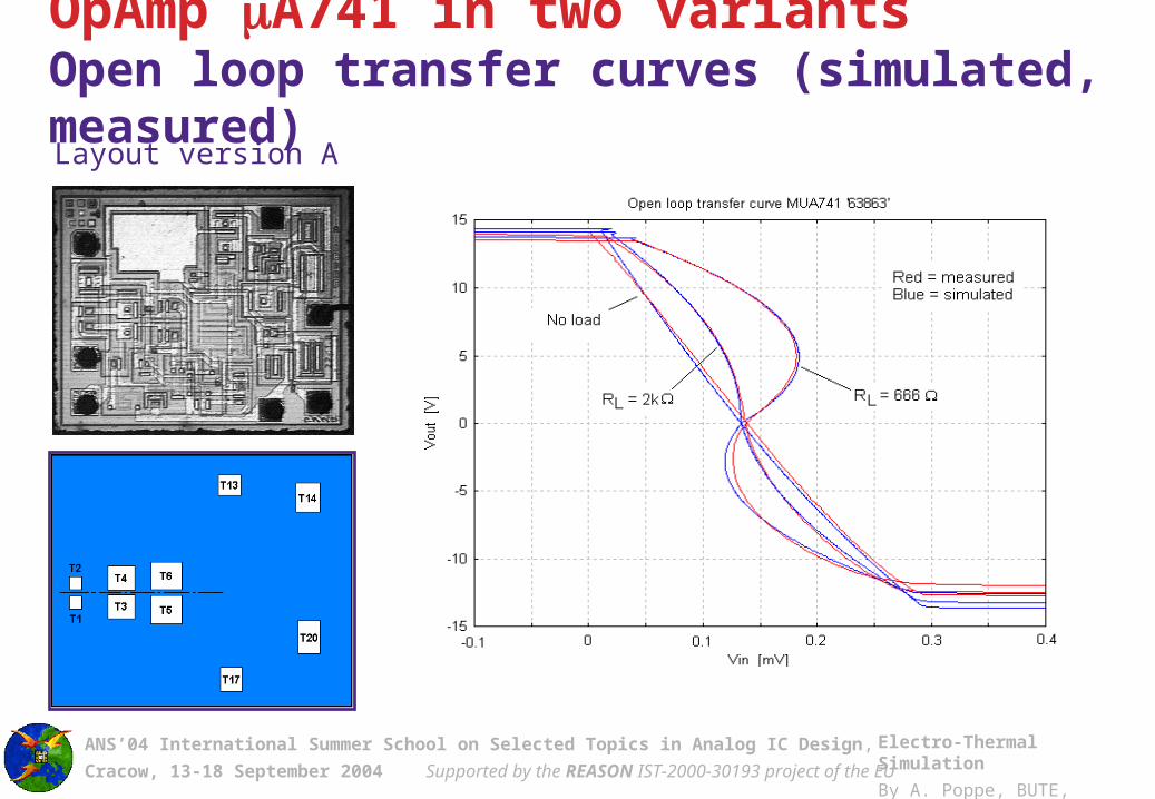
ANS’04 International Summer School on Selected Topics in Analog IC Design,
Cracow, 13-18 September 2004 Supported by the REASON IST-2000-30193 project of the EU
Electro-Thermal Simulation
By A. Poppe, BUTE, Hungary
OpAmp A741 in two variantsOpen loop transfer curves (simulated, measured) Layout version A

ANS’04 International Summer School on Selected Topics in Analog IC Design,
Cracow, 13-18 September 2004 Supported by the REASON IST-2000-30193 project of the EU
Electro-Thermal Simulation
By A. Poppe, BUTE, Hungary
OpAmp A741 in two variantsOpen loop transfer curves (simulated, measured)
Layout version B

ANS’04 International Summer School on Selected Topics in Analog IC Design,
Cracow, 13-18 September 2004 Supported by the REASON IST-2000-30193 project of the EU
Electro-Thermal Simulation
By A. Poppe, BUTE, Hungary
)()()(1
)(
)(1)( 214114
ZZγVVωGβ
ωG
ωGβ
RωZ OUTCC
v
v
v
eOUT
OpAmp A741 in two variantsFrequency domain behavior Thermal effects on the output impedance
Re – open loop electrical resistance
Gv() – open loop gain
= R2/(R1+R2) – electrical feedback factor

ANS’04 International Summer School on Selected Topics in Analog IC Design,
Cracow, 13-18 September 2004 Supported by the REASON IST-2000-30193 project of the EU
Electro-Thermal Simulation
By A. Poppe, BUTE, Hungary
This effect appears in the unloaded opamp!
OpAmp A741 in two variantsFrequency domain behavior
Layout A, transistor T14 operates, G=104
Thermal effects on the output impedance

ANS’04 International Summer School on Selected Topics in Analog IC Design,
Cracow, 13-18 September 2004 Supported by the REASON IST-2000-30193 project of the EU
Electro-Thermal Simulation
By A. Poppe, BUTE, Hungary
OpAmp A741 in two variantsFrequency domain behavior
Layout version A
These chips differ only in the component arrangement!
Layout version B
Thermal effects on the output impedance

ANS’04 International Summer School on Selected Topics in Analog IC Design,
Cracow, 13-18 September 2004 Supported by the REASON IST-2000-30193 project of the EU
Electro-Thermal Simulation
By A. Poppe, BUTE, Hungary
Experimental validationStudy of micromachined RMS meter

ANS’04 International Summer School on Selected Topics in Analog IC Design,
Cracow, 13-18 September 2004 Supported by the REASON IST-2000-30193 project of the EU
Electro-Thermal Simulation
By A. Poppe, BUTE, Hungary
Example: An electro-thermal converter (RMS meter)
Thermopile
Heater

ANS’04 International Summer School on Selected Topics in Analog IC Design,
Cracow, 13-18 September 2004 Supported by the REASON IST-2000-30193 project of the EU
Electro-Thermal Simulation
By A. Poppe, BUTE, Hungary
Example: An electro-thermal converter (RMS meter)
Steady state results

ANS’04 International Summer School on Selected Topics in Analog IC Design,
Cracow, 13-18 September 2004 Supported by the REASON IST-2000-30193 project of the EU
Electro-Thermal Simulation
By A. Poppe, BUTE, Hungary
Example: An electro-thermal converter (RMS meter)
Frequency domain results

ANS’04 International Summer School on Selected Topics in Analog IC Design,
Cracow, 13-18 September 2004 Supported by the REASON IST-2000-30193 project of the EU
Electro-Thermal Simulation
By A. Poppe, BUTE, Hungary
Example: An electro-thermal converter (RMS meter)
Transient results
The transient simulation shows the characteristic frequency doubling feature of the electro-thermal converter

ANS’04 International Summer School on Selected Topics in Analog IC Design,
Cracow, 13-18 September 2004 Supported by the REASON IST-2000-30193 project of the EU
Electro-Thermal Simulation
By A. Poppe, BUTE, Hungary
OUTLOOK, SUMMARY, LITERATURE

ANS’04 International Summer School on Selected Topics in Analog IC Design,
Cracow, 13-18 September 2004 Supported by the REASON IST-2000-30193 project of the EU
Electro-Thermal Simulation
By A. Poppe, BUTE, Hungary
Outlook: logi-thermal simulation

ANS’04 International Summer School on Selected Topics in Analog IC Design,
Cracow, 13-18 September 2004 Supported by the REASON IST-2000-30193 project of the EU
Electro-Thermal Simulation
By A. Poppe, BUTE, Hungary
• Gate delays may depend on temperature• Dissipation of one switching event may depend on temperature• Switching density dissipation density temperature distribution
Temperature gradients observed on a digital VLSI chip, both by simulation and LC imaging (1.5 micron CMOS @ 25 MHz)
Logi-thermal simulationLogic level simulation + thermal effects
Temperature measured on test chip (320mW dissipation in a corner of a 6x6mm2 chip)

ANS’04 International Summer School on Selected Topics in Analog IC Design,
Cracow, 13-18 September 2004 Supported by the REASON IST-2000-30193 project of the EU
Electro-Thermal Simulation
By A. Poppe, BUTE, Hungary
• THERMAN• Verilog• Design framework
(Cadnece Opus)
• Initial work: – G. Hajas (BUTE), 1997
• Recent experiments:– K. Torki (TIMA), 2003
Logi-thermal simulationExperimental setup:
V e r i l o g - X L
S i m u l a t o r
S i g n - o f f
T e s t b e n c h
L E F
L i b r a r y
T L F
L i b r a r y
W a v e f o r m s
B a c k a n n o t a t e d N e t l i s t
+
T i m i n g ( . s d f )
T e s t B e n c h
1
C u s t o m i z e d
P L I
V C D
S y s t e m
T a s k
I n t e r a c t i v e
T o g g l e c o u n t
f i l e
. t c f
V C D D u m p f i l e
. v c d
P o s t - P r o c e s s o r
P o w e r C a l c u l a t i o n
T i m i n g F i l e
. s d f
P h y s i c a l
R e p r e s e n t a t i o n
T H E R M A N
V c d 2 T c f
T H E R M A N i n p u t
. t h c
V i r t u o s o
C a d e n c e l a y o u t
S K I L L
P r o c e d u r e
I C T o t a l P o w e r
S t i m u l i F i l e
H D L - A
S i m u l a t o r
H D L - A p a c k a g e
M o d e l
P a c k a g e T h e r m a l
R e s p o n s e
C i r c u i t T h e r m a l M a pC e l l s T h e r m a l M a p
• See also: K. Skadron et al, Univ. of Virginia, USA

ANS’04 International Summer School on Selected Topics in Analog IC Design,
Cracow, 13-18 September 2004 Supported by the REASON IST-2000-30193 project of the EU
Electro-Thermal Simulation
By A. Poppe, BUTE, Hungary
Logi-thermal simulation examplesDesign layout
Digital circuit with 2 RAM blocks (0.6µm CMOS, 20k gates, 40 MHz, 15mm2).
Maximum temperature gradient was 14 degrees.

ANS’04 International Summer School on Selected Topics in Analog IC Design,
Cracow, 13-18 September 2004 Supported by the REASON IST-2000-30193 project of the EU
Electro-Thermal Simulation
By A. Poppe, BUTE, Hungary
Temperature profile of a 32x32 bits combinational multiplier, (0.18µm CMOS,
7k gates, 200MHz, 0.085 mm2)
Logi-thermal simulation examplesDesign layout

ANS’04 International Summer School on Selected Topics in Analog IC Design,
Cracow, 13-18 September 2004 Supported by the REASON IST-2000-30193 project of the EU
Electro-Thermal Simulation
By A. Poppe, BUTE, Hungary
Other problems
• many wire layers (contacts)• self-heating of the wires

ANS’04 International Summer School on Selected Topics in Analog IC Design,
Cracow, 13-18 September 2004 Supported by the REASON IST-2000-30193 project of the EU
Electro-Thermal Simulation
By A. Poppe, BUTE, Hungary
Summary & literature

ANS’04 International Summer School on Selected Topics in Analog IC Design,
Cracow, 13-18 September 2004 Supported by the REASON IST-2000-30193 project of the EU
Electro-Thermal Simulation
By A. Poppe, BUTE, Hungary
Summary
• Electro-thermal simulation in IC/MEMS design is needed if– parasitic effects due to thermal phenomena are present
• undesired thermal feedback
– the goal is the design of systems utilizing some thermal principle
• sensors, other converters
• Electro-thermal simulation is an extension of ordinary circuit simulation. There are two usual methods:– simulator coupling– direct method or simultaneous simulation – this is the
preferred one

ANS’04 International Summer School on Selected Topics in Analog IC Design,
Cracow, 13-18 September 2004 Supported by the REASON IST-2000-30193 project of the EU
Electro-Thermal Simulation
By A. Poppe, BUTE, Hungary
Summary (cont.)
• In case of electro-thermal simulation real electro-thermal device models are needed– thermal node / thermal branch– temperature dependence of model parameters– dissipation equation– thermal derivatives: all elements of the Jacobian are needed
• Thermal nodes of electro-thermal device models are terminated by the ports of the thermal model of the IC chip.
• The thermal model of the IC chip must be correct and must be handled by the network solver efficiently

ANS’04 International Summer School on Selected Topics in Analog IC Design,
Cracow, 13-18 September 2004 Supported by the REASON IST-2000-30193 project of the EU
Electro-Thermal Simulation
By A. Poppe, BUTE, Hungary
Summary (cont.)
• Different simulation case studies have been presented– OTA:
• difference between electrical-only and electro-thermal simulation• layout dependent behavior (thermal feedback path)
– OpAmp:• effect of the thermal feedback – DC offset voltage• effect of the layout – symmetrical layout: symmetrical characteristics• output impedance is also influenced• frequency domain behavior differs for different layouts• symmetry considerations in layout design are very important• even the packaging structure influences electrical behavior via
thermal effects (coupling)Symmetrical layout is needed – not only for matching rules but for
thermal REASONs, too

ANS’04 International Summer School on Selected Topics in Analog IC Design,
Cracow, 13-18 September 2004 Supported by the REASON IST-2000-30193 project of the EU
Electro-Thermal Simulation
By A. Poppe, BUTE, Hungary
Summary (cont.)
• Different simulation case studies have been presented– some MEMS devices / thermal functional circuits have been
studied with success• RMS meter: Seebeck-effect was used for sensing (simulated,
measured)• micro hot-plate: temperature dependent resistor was used for sensing• micro thermostate: CMOS temp. sensor + strong coupling, effect of
packaging was properly simulated (simulated, measured)

ANS’04 International Summer School on Selected Topics in Analog IC Design,
Cracow, 13-18 September 2004 Supported by the REASON IST-2000-30193 project of the EU
Electro-Thermal Simulation
By A. Poppe, BUTE, Hungary
Some literature[1] W.V. Petegem et al. “Electro-thermal simulation and design of integrated circuits” IEEE Journal of. Solid State Circuits, SSC-29(2):143, 1994.[2] W.H. Kao, W.K. Chu. “ATLAS: An Integrated Thermal Layout and Simulation System of IC-s” In Proc. of ED&TC’94, Paris, France, March 1994. [3] Y-K. Cheng et al. “ETS-A: A New Electrothermal Simulator for CMOS VLSI Circuits” In Proc. of ED&TC’96, pp. 566-570, Paris, France, March 1996.[4] T. Li, C.H. Tsai, S.M. Kang: “Efficient Transient Electrothermal Simulation of CMOS VLSI Circuits under Electrical Overstress” In Proc. of ICCAD’98,San Jose, CA, USA, 1998, pp.6-10[5] S.S. Lee, D.J. Allstot: Electrothermal simulation of integrated circuits, IEEE Journal of Solid-State Circuits, SSC-28(12):1283-1293, 1993[6] G. Digele et al. “Fully coupled Dynamic Electro-Thermal Simulation” IEEE Transactions on VLSI Systems, 5(3):250-257, 1997[7] M.N. Sabry et al. “Realistic and Efficient Simulation of Electro-Thermal Effects in VLSI Circuits” IEEE Tr. on VLSI Systems, 5(3):283-289, 1997.[8] S. Wunsche, C. Claub, P. Schwarz: “Electro-Thermal Circuit Simulation Using Simulator Coupling”, IEEE Trans. On VLSI Systems, Vol.5,No.3, ,pp 277-282, 1997

ANS’04 International Summer School on Selected Topics in Analog IC Design,
Cracow, 13-18 September 2004 Supported by the REASON IST-2000-30193 project of the EU
Electro-Thermal Simulation
By A. Poppe, BUTE, Hungary
Some literature (cont.)[9] V. Székely et al. “Self-consistent electro-thermal simulation: fundamentals and practice” Microelectronics Journal, 28:247-262, 1997.[10] V. Székely et.al.: Electro-thermal and logi-thermal simulation of VLSI designs, IEEE Transactions on VLSI Systems, 5(3):258-269, 1997[11] T. Veijola et al. “An implementation of electro-thermal component models in a general purpose circuit simulation program” In Proc. of the 3rd THERMINIC Workshop, pp. 96-100, Cannes, France, September 1997[12] V. Székely: “Accurate calculation of device heat dynamics: a special feature of the Trans–Tran circuit analysis program”, Electronics Letters,Vol 9,no.6,pp.132-134 (1973)[13] V. Székely et al. “SISSSI - a tool for dynamic electro-thermal simulation of analog VLSI cells” Proc. of ED&TC’97, p. 617, Paris, France, March 1997.[14] M. Rencz et al: “An alternative method for electro-thermal circuit simulation” In Proc. of SSMSD’99, pp 117-122, Tucson, AZ, USA, 1999.[15] L. T. Pillage, R. A. Rohrer: Asymptotic waveform evaluation for timing analysis, IEEE Transactions on Computer-Aided Design, CAD-.9(4):352-366, 1990[16] V. Székely: Identification of RC Networks by Deconvolution: Chances and Limits, IEEE Transactions on Circuits and Systems-I. Theory and Applications, CAS-45(3):244-258, 1998

ANS’04 International Summer School on Selected Topics in Analog IC Design,
Cracow, 13-18 September 2004 Supported by the REASON IST-2000-30193 project of the EU
Electro-Thermal Simulation
By A. Poppe, BUTE, Hungary
Some literature (cont.)[17] V. Székely, A. Poppe, M. Rencz, M. Rosental, T. Teszéri: THERMAN: a thermal simulation tool for IC chips, microstructures and PW boards. Microelectronics Reliability, Vol. 40, pp. 517-524, 2000[18] J.E. Solomon: “The monolithic Op Amp: A tutorial”, IEEE Journal of Solid-state circuits, Vol.SC-9, No. 6,Dec. 1974, pp 314-332[19] M. Rencz, V. Székely, A. Poppe: A fast algorithm for the layout based electro-thermal simulation, DATE 2003, March 3-7 2003 Munich, proc. pp. 1032-1037[20] C. Enz, F. Krummenacher, E. Vittoz, 'An analytical MOS transistor model valid in all regions of operation and dedicated to low-voltage and low-current applications', Journal on Analog Integrated Circuits and Signal Processsing, Kluwer Academic Publishers, pp. 83-114, July 1995[21] http://legwww.epfl.ch/ekv [22] V. Székely, S.Török: Verification of an electro-thermal simulation algorithm, 9th Therminic Workshop, 24-26 September 2003, Aix-en-Provence, France, pp.233-238

ANS’04 International Summer School on Selected Topics in Analog IC Design,
Cracow, 13-18 September 2004 Supported by the REASON IST-2000-30193 project of the EU
Electro-Thermal Simulation
By A. Poppe, BUTE, Hungary
Acknowledgements

ANS’04 International Summer School on Selected Topics in Analog IC Design,
Cracow, 13-18 September 2004 Supported by the REASON IST-2000-30193 project of the EU
Electro-Thermal Simulation
By A. Poppe, BUTE, Hungary
AcknowledgementThe work of the following colleagues at BUTE and TIMA Laboratory (Grenoble, France) is acknowledged
V. Székely, M. Renczproject leadership, development of algorithms & models
A. Páhiprogramming, layout design
G. Hajas, G. Mezei, Gy. Horváth programming
S. Török, I. Hajas, T. Unyatinszki, G. Végh measurements
B. Courtois, B. Charlot, K. Torki support of our initial work, manufacturing benchmark circuits and MEMS structures
The support of the THERMINIC, DETERMIN, PROFIT and REASON projects of the EU, and different OTKA projects of the Hungarian National Scientific Research Fund is also acknowledged.

ANS’04 International Summer School on Selected Topics in Analog IC Design,
Cracow, 13-18 September 2004 Supported by the REASON IST-2000-30193 project of the EU
Electro-Thermal Simulation
By A. Poppe, BUTE, Hungary
The End
Thanks for your attention