Annihilation /spl gamma/ Ray Background …miil.stanford.edu/publications/files/110_PUB.pdf ·...
7
1120 IEEE TRANSACTIONS ON NUCLEAR SCIENCE, VOL. 44, NO 3, JUNE 1997 Annihilation y Ray Background Characterization and Rejection for a Small Beta Camera Used for Tumor Localization During Surgery Craig S. Levin, Member, ZEEE, Martin P. Tomai, Student Member, IEEE, Lawrence R. MacDonald, Student Member, IEEE, and Edward J. Hoffman, Senior Member, IEEE Division of Nuclear Medicine and Biophysics, UCLA School of Medicine Los Angeles, CA 90095-6948 Abstract We have developed a miniature (1.2 cm2)beta-ray camera prototype to assist a surgeon in locating the margins of a resected tumor. With this technique, one directly detects betas emitted from exposed radio-labeled tissue. When imaging positron emitting radiopharmaceuticals, annihilation gamma ray interactions in the detector can mimic those of the betas. The extent of the background contamination depends on the detector, geometry and the tumor specificity of the radiopharmaceutical. We have characterized the effects that annihilation gamma rays have on positron imaging with our small camera. We studied beta and gamma ray detection rates and imaging using small positron or electron sources directly exposed to the detector to simulate hot tumor remnants, and a cylinder filled with 18F to simulate annihilation background from the brain. For various ratios of phantom headltumor activity, a background gamma rate of 2.0 ctsIseclyCi was measured in the CaF2(Eu) detector. We present two gamma- ray background rejection schemes that require a p-y coincidence. The first configuration uses a high efficiency scintillator coincidence "shield', the second, a "phoswich". Results show that these coincidence methods work with -99% gamma ray rejection efficiency. I. INTRODUCTION We have developed [ 1-1 11 miniature (51.2 cm2), gamma (y) and beta (p) ray imaging scintillation camera prototypes for the purpose of assisting a surgeon in locating and removing the margins of a resected tumor. The p imaging device directly detects positrons (p') or electrons (p-) emitted from radiolabeled tissue exposed during surgery. The short range of the p's in tissue and detector and close proximity imaging of the activity (lesion) ensure high sensitivity and resolution with no need for a collimator. Imaging capabilities in situ help to distinguish signal from background and allow a relatively large area to be assayed in a relatively short time. Most of the pure p emitting radiopharmaceuticals readily available and used in the nuclear medicine clinic for tumor imaging are p+ emitters (usually 1813-labeled) for Positron Emission Tomography (PET). Using p+ emitters, the detector will measure activity from annihilation y rays (background) as well as from p+s (signal). The ability to extract the true j3 activity image from the total p and background y signal depends on the ratio of tumor to background activity rates observed. This, in turn, depends on the radiopharmaceutical tumor uptake specificity. For tumor localization during Neurosurgery, a candidate radiopharmaceutical for use in conjunction with this surgical probe is 18F-Fluorodeoxyuridine (FdUr). UCLA PET studies with this tracer have shown brain tumor to normal tissue uptake ratios as high as 10: 1. The detected ply rate ratio also depends on the y ray efficiency of the scintillator. To minimize this background contamination, the scintillator chosen for the device is p sensitive, yet relatively y ray insensitive (low Z, low density). The scintillator should be as thin as possible (for lower y ray efficiency), but thick enough to stop most of the p rays from the source (for higher light output and sensitivity) [4, 51. There are a few techniques one might use for gamma ray background (GRB) rejection for non-imaging p probes detecting P+s. One idea is to only accept those detected events above an energy threshold which corresponds to the Compton edge of the background y ray spectrum [ 121. This approach, however, has the problem of a greatly reduced sensitivity, since low energy p events (a large proportion of all events) will be cut out as well. In addition, due to relatively poor energy resolution, the Compton edge is ill-defined and may significantly spread into higher energies. A second technique [13] employed with a non-imaging p detecting probe, uses a second concentric detector to estimate y- only activity. Data is acquired simultaneously in both detectors and the p-only component is determined by subtracting the suitably weighted counts measured in the second detector from that counted in the first. The main disadvantages of this technique were that (1) a correct and precise determination of the weighting factor that is valid for all background yray source distributions is difficult and (2) the second detector was inefficient for y rays. In this work we propose two new "on-line" background rejection schemes for an imaging device, both of which use beta-gamma (p-y) coincidence detection. GRB rejection is achieved by requiring a detected coincidence between CaF$(Eu), the primary p detector, and an adjacent secondary detector that detects the associated y ray. We will demonstrate the method using I8F, a pf emitter used as a label for tumor detection in PET. With p's there are two y rays associated with each p event detected. The P-y coincidence GRB rejection scheme is especially useful for p+ annihilation GRB removal. Since two y rays are emitted roughly 180" apart this ensures a high geometric efficiency for detection of at least one. However, this GRB rejection technique could, in principle, be useful for any O-emitting pharmaceutical (such as 1311) that has an accompanying y ray. 11. METHODS A. Annihilation Background Characterization Figure 1 shows the schematic of the basic experimental set-up used to characterize the effect of GRB on p detection and imaging with the surgical imaging probe. Details of the imaging device are described elsewhere [5]. Fiber optics read out the scintillation light from a 1.25 cm diameter CaF2(Eu) 0018-9499/97$10.00 0 1997 IEEE Authorized licensed use limited to: Stanford University. Downloaded on June 01,2010 at 20:47:41 UTC from IEEE Xplore. Restrictions apply.
Transcript of Annihilation /spl gamma/ Ray Background …miil.stanford.edu/publications/files/110_PUB.pdf ·...

1120 IEEE TRANSACTIONS ON NUCLEAR SCIENCE, VOL. 44, NO 3, JUNE 1997
Annihilation y Ray Background Characterization and Rejection for a Small Beta Camera Used for Tumor Localization During Surgery
Craig S. Levin, Member, ZEEE, Martin P. Tomai, Student Member, IEEE, Lawrence R. MacDonald, Student Member, IEEE, and Edward J. Hoffman, Senior Member, IEEE
Division of Nuclear Medicine and Biophysics, UCLA School of Medicine Los Angeles, CA 90095-6948
Abstract
We have developed a miniature (1.2 cm2) beta-ray camera prototype to assist a surgeon in locating the margins of a resected tumor. With this technique, one directly detects betas emitted from exposed radio-labeled tissue. When imaging positron emitting radiopharmaceuticals, annihilation gamma ray interactions in the detector can mimic those of the betas. The extent of the background contamination depends on the detector, geometry and the tumor specificity of the radiopharmaceutical. We have characterized the effects that annihilation gamma rays have on positron imaging with our small camera. We studied beta and gamma ray detection rates and imaging using small positron or electron sources directly exposed to the detector to simulate hot tumor remnants, and a cylinder filled with 18F to simulate annihilation background from the brain. For various ratios of phantom headltumor activity, a background gamma rate of 2.0 ctsIseclyCi was measured in the CaF2(Eu) detector. We present two gamma- ray background rejection schemes that require a p-y coincidence. The first configuration uses a high efficiency scintillator coincidence "shield', the second, a "phoswich". Results show that these coincidence methods work with -99% gamma ray rejection efficiency.
I. INTRODUCTION
We have developed [ 1-1 11 miniature (51.2 cm2), gamma (y) and beta (p) ray imaging scintillation camera prototypes for the purpose of assisting a surgeon in locating and removing the margins of a resected tumor. The p imaging device directly detects positrons (p') or electrons (p-) emitted from radiolabeled tissue exposed during surgery. The short range of the p's in tissue and detector and close proximity imaging of the activity (lesion) ensure high sensitivity and resolution with no need for a collimator. Imaging capabilities in situ help to distinguish signal from background and allow a relatively large area to be assayed in a relatively short time. Most of the pure p emitting radiopharmaceuticals readily available and used in the nuclear medicine clinic for tumor imaging are p+ emitters (usually 1813-labeled) for Positron Emission Tomography (PET). Using p+ emitters, the detector will measure activity from annihilation y rays (background) as well as from p+s (signal). The ability to extract the true j3 activity image from the total p and background y signal depends on the ratio of tumor to background activity rates observed. This, in turn, depends on the radiopharmaceutical tumor uptake specificity. For tumor localization during Neurosurgery, a candidate radiopharmaceutical for use in conjunction with this surgical probe is 18F-Fluorodeoxyuridine (FdUr). UCLA PET studies with this tracer have shown brain tumor to normal tissue uptake ratios as high as 10: 1.
The detected p ly rate ratio also depends on the y ray efficiency of the scintillator. To minimize this background contamination, the scintillator chosen for the device is p sensitive, yet relatively y ray insensitive (low Z, low density). The scintillator should be as thin as possible (for lower y ray efficiency), but thick enough to stop most of the p rays from the source (for higher light output and sensitivity) [4, 51.
There are a few techniques one might use for gamma ray background (GRB) rejection for non-imaging p probes detecting P+s. One idea is to only accept those detected events above an energy threshold which corresponds to the Compton edge of the background y ray spectrum [ 121. This approach, however, has the problem of a greatly reduced sensitivity, since low energy p events (a large proportion of all events) will be cut out as well. In addition, due to relatively poor energy resolution, the Compton edge is ill-defined and may significantly spread into higher energies.
A second technique [13] employed with a non-imaging p detecting probe, uses a second concentric detector to estimate y- only activity. Data is acquired simultaneously i n both detectors and the p-only component is determined by subtracting the suitably weighted counts measured in the second detector from that counted in the first. The main disadvantages of this technique were that (1) a correct and precise determination of the weighting factor that is valid for all background yray source distributions is difficult and (2) the second detector was inefficient for y rays.
In this work we propose two new "on-line" background rejection schemes for an imaging device, both of which use beta-gamma (p-y) coincidence detection. GRB rejection is achieved by requiring a detected coincidence between CaF$(Eu), the primary p detector, and an adjacent secondary detector that detects the associated y ray. We will demonstrate the method using I8F, a pf emitter used as a label for tumor detection in PET. With p's there are two y rays associated with each p event detected. The P-y coincidence GRB rejection scheme is especially useful for p+ annihilation GRB removal. Since two y rays are emitted roughly 180" apart this ensures a high geometric efficiency for detection of at least one. However, this GRB rejection technique could, in principle, be useful for any O-emitting pharmaceutical (such as 1311) that has an accompanying y ray.
11. METHODS
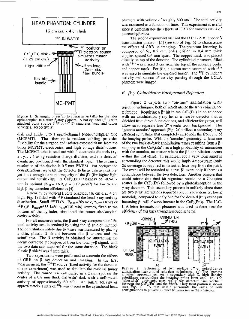
A. Annihilation Background Characterization Figure 1 shows the schematic of the basic experimental
set-up used to characterize the effect of GRB on p detection and imaging with the surgical imaging probe. Details of the imaging device are described elsewhere [5] . Fiber optics read out the scintillation light from a 1.25 cm diameter CaF2(Eu)
0018-9499/97$10.00 0 1997 IEEE
Authorized licensed use limited to: Stanford University. Downloaded on June 01,2010 at 20:47:41 UTC from IEEE Xplore. Restrictions apply.
1121
phantom with volume of roughly 800 cm3. The total activity was measured as a function of time. This experiment is useful since it demonstrates the effects of GRB for various ratios of detected ylp rates.
The second experiment utilized the U-C-L-A #1 copper p transmission phantom [5] (see top of Fig. 6) to characterize the effects of GRB on imaging. The phantom lettering is composed of 61, 0.5 mm holes drilled in 0.4 mm thick copper, spaced 0.6 mm apart. The copper mask was placed directly on top of the detector The cylindrical phantom, filled with 18F was placed 3 cm from the top of the imaging probe and copper mask. For fits, a cotton swab saturated with 18F was used to simulate the exposed tumor. The lSF cylinder y activity and source p' activity passing through the UCLA phantom were imaged.
HEAD PHANTOM: CYLINDER 16 cm dia x 4 cm high
'8F IN WATER
2 0 4 ~ ~ electron source simulates tumor
MC-PMT U Figure 1. Schematic of set up to characterize GRB for the fiber optic-coupled miniature Ray Camera. A hot cylinder (18F) with attached point source (piF or 204Tl) simulates head and tumor activities, respectively.
disk and guide it to a multi-channel photo-multiplier tube (MCPMT). The fiber optic readout cabling provides flexibility for the surgeon and isolates exposed tissue from the bulky MCPMT, electronics, and high voltage distributions. The MCPMT tube is read out with 4 electronic channels (x+, x-, y+, y-) using resistive charge division, and the detected events are positioned with the standard logic. The intrinsic resolution of the device is 0.5 mm FWHM. For background considerations, we want the detector to be as thin as possible, yet thick enough to stop a majority of the p's (for higher light output and sensitivity). A CaF2(Eu) thickness of -0.5-0.7 mm is optimal (Z,,= 16.9, p = 3.17 g/cm3) for low y- and high p-ray detection efficiencies [4].
A near by cylindrical Lucite phantom (16 cm dia., 4 cm high, Fig. 1) filled with 18F simulated the head yray activity distribution. Small 204Tl (p-, E,a,=765 keV, 21/2=3.8 yr) or 18F (p+, Ema,=635 keV, ~ ~ , ~ = 1 1 0 min) sources, fixed to the bottom of the cylinder, simulated the tumor sitehrgical cavity activity.
For all measurements, the p and y ray components of the total activity are determined by using the "p shield" method. The contribution solely due to y rays was measured by placing a thin, plastic p shield between the p source and the scintillator. The p activity is obtained by subtracting the decay corrected y component from the total yi-p signal, with the two data sets acquired for the same duration. The black plastic p shield was 5 mm thick.
Two experiments were performed to ascertain the effects of GRB on p ray detection and imaging. In the first measurement, the 204Tl source (fixed activity for the duration of the experiment) was used to simulate the residual tumor activity. The source was collimated in a 2 mm spot on the center of a 0.8 mm thick CaFz(Eu) disk with a collimated activity of approximately 60 nCi. An initial activity of approximately 1 mCi of 18F was placed in the cylindrical head
B. p- y Coincidence Background Rejection
Figure 2 depicts two "on-line" annihilation GRB rejection techniques, both of which utilize the P+-y coincidence technique. Requiring a pt hit in the CaF,(Eu) in coincidence with an annihilation y ray hit in a nearby detector that is shielded from direct p interactions, and efficient for y rays, will allow us to separate true p+ events from background. The "gamma annulus" approach (Fig. 2a) utilizes a secondary y ray efficient scintillator that completely surrounds the front end of the imaging probe. With the "annulus" geometry, at least one of the two back-to-back annihilation y rays resulting from a p' stopping in the CaF2(Eu) has a high probability of interacting with the annulus, no matter where the p' annihilation occurs within the CaF2(Eu). In principal, for a very long annulus surrounding the detector, this would imply 47c coverage (only 2n: coverage is required to detect at least one from the pair). The event will be recorded as a true p+ event only if there is a coincidence between the two detectors. Another process that could mimic this dual hit signature would be a Compton scatter in the CaF2(Eu) followed by a photoabsorption in the y ray detectoi. This secondary process is unlikely since there are two 'y-ray interactions required (one in a low density, low Z material), compared to only one for the desiied P+-y even1 (an incoming p' will always interact in the CaFz(Eu)). The U-C- L-A letter transmission phantom was used to determine the efficiency of this background rejection scheme.
(a) (b) Figure 2. Schematic of two on-line p + - cointidence annihilation back round rejection techniques ?a) The amma annulus" approac5 utilizes a secondary hi h Z, high fensity scintillator surrounding the imaging probe front end. (b) Th? "phoswich" ap roach, uses the y ra between the CaFz(Eu) and the fibers. dnly front portion is shown (see Flg. 1). A thin shield surrounds the sides of both configurations to prevent a direct p+ interaction in the y detector
detector "sandwiched
Authorized licensed use limited to: Stanford University. Downloaded on June 01,2010 at 20:47:41 UTC from IEEE Xplore. Restrictions apply.

1122
The "phoswich" [ 14, 151 approach (Fig. 2b), uses a y ray efficient detector (assume GSO, for example) that is both much faster than CaF,(Eu), and is transparent to its blue scintillation light, This scintillator is "sandwiched" between the CaF,(Eu) and the fiber bundle. The GSO serves the dual purpose of the fast y-ray detector and the light diffuser required for the continuous CaF2(Eu) scintillator imaging [4,5].
In the phoswich configuration, the differences in both decay time and light output between the CaFz(Eu) (slow decay -1 p) and the GSO (fast decay, 60 ns) allows one to use pulse shape discrimination methods to identify the coincident events of interest. The events are clearly distinguishable because the decay times of the two scintillators differ by more than a factor of 10. An annihilation y ray associated with the p+ of interest will very likely traverse the secondary detector and a good event will have a signature of two added pulses: one slow (CaF,(Eu)) and one fast (GSO). By triggering on the rise of the fast decay portion of the signal, delaying by the decay time of that pulse (typically ~ 2 0 0 ns), and then integrating the slow portion of the pulse, nearly 90% of the true p+ signal will be extracted. This is accomplished with the use of a fast leading edge or constant fraction discriminator, set above the CaF,(Eu) amplitudes, to trigger a linear gate for the amplified positioning signals of the imaging probe. The linear gate is normally closed and will open with a delayed signal from the y ray detector trigger. This technique works best with high efficiency detectors that are both fast and have high light yield.
As with essentially all background rejection schemes, the p+-y coincidence method results in an overall reduction in sensitivity. The extent of reduction depends on the detection efficiency of the y ray detector. In principal, if that detector has a high stopping power for 5 I I keV y rays, and subtends a large solid angle to the CaF2(Eu) (see Fig. 2), for all positions within the CaFz(Eu), the coincident sensitivity of the system will be acceptable.
For both P+-y coincidence rejection schemes, the efficiency of the y ray rejection can be measured by comparing the detected y/P ratio with and without the P+-y coincidence. (recall the y/P ratio is measured using a "beta-shield"). In addition, if we block the p ' s from the CaF2(Eu) during coincidence acquisition, the resulting events seen are due to the background y-y process (for example, a Compton scatter in the CaF2(Eu) followed by a photoabsorption in the adjacent y ray detector). The number of coincident events measured with the p absorber in place compared to that without, when the two data sets are acquired for an equal amount of time (with decay correction), determines how often two y ray interactions mimic a P - y event.
I - :
111, RESULTS
A. Beta and Annihilation Gamma Ray Activity Rates
: ' " ' " r 1 ' I ' z ' I 8 ' ' " ' ' " 1
FOR PHANTOM ' *F HEAD
Figure 3 shows y+P, y and f3 spectra measured for different 8F cylinder activity levels (simulating head activity) with an attached *04Tl p source (simulating residual tumor activity). We see that even for this very thin CaF2(Eu) disk (0.8 mm thick, 1.25 diameter) that the GRB detection rate is significant. For the second through fourth spectra, the y component dominates the measured activity. As the activity in the phantom decays, the constant 204Tl activity (beta spec-
837 pCi ' SF IN PHANTOM
BETA + GAMMA
418 pCi IN PHANTOM I I ,, 151 pCi IN PHANTOM
I
F 'igure 3. Some y+p, y and p ctivities measured for various ' phantom activity ,levels, (284TI p source). annihilation GRB rejection is evident. See Figure 4.
The need for
a
0 5 10 15 PHANTOM HEAD/TUMOR ACTIVITY RATIO (x103 )
Figure 4. Measured annihilation y ('*F) to p (*04Tl) rate ratio in the camera front end as a function of phantoq qead to tumor activity ratio (see Fig. 1). The collimated T1 p source corresponded to approximately 60 nCi.
Authorized licensed use limited to: Stanford University. Downloaded on June 01,2010 at 20:47:41 UTC from IEEE Xplore. Restrictions apply.

1123
tumor (P source) to head (cylinder) uptake by volume (e.g. using FdUr) implies -480 pCi in the head (cylinder). From Figure 4, this implies an expected activity ylp rate ratio of approximately 3:1, which means some sort of GRB rejection scheme may be necessary. To reiterate, the relative, rather than absolute, residual tumor to head activity levels is the important quantity. For lower tumor to tissue uptake ratios the GRB problem will be worse (yip rate ratio will be higher).
For CaF,(Eu) thickness < 1.6 mm, 18F flood irradiation studies showed both the y and y/P activity to increase linearly with thickness. Figure 5 shows the results for the ratio of detected y to (3 rates as a function of several ratios of 18F phantom head to 18F tumor activity levels for a 0.8 mm thick detector. The extent of GRB contamination for a given I8F tumor seeking radiopharmaceutical can be determined from this figure, once the brain to tumor activity is known. For example, a phantom headltumor activity ratio of 4000:l implies that the detected y/P ratio is approximately 1.3: 1. The detected y rate was roughly 2.0 ctslseclpci €or this measurement which compares well to the 204Tl measurement of Figure 4. Note that for the y/P detected rates as a function of headhumor concentration instead of activity ratio, one must know the approximate tumor volume.
FOR PHANTOM '*F HEAD ' E 4 1 ANDTUMOR L 4
a 3
ilJ
E z
".I I = I
I 3 I 5 10 15 20 25
PHANTOM HEAD~TUMOR ACTIVITY RATIO (xi031 Pi ure 5. y/p detected rate ratio as a function of various 18F cyfnder /source (simulating headtumor) activity levels.
B. EfSect of Annihilation yRays on Beta Imaging
Figure 6 demonstrates the potential problem of annihilation GRB for p imaging with this camera. Images were obtained using the U-C-L-A #I copper transmission phantom (shown at top) on the p imaging probe irradiated with 1OOpCi of either 204Tl (p-s, left image) or 18F (p+s, right). The 1SF image shown was acquired with no activity in the head phantom so it represents the best case scenario in terms of GRB. The potential need for annihilation background rejection is evident. The presence of P' annihilation GRB generated within the cotton swab, and/or the CaF2(Eu) is evident as a loss of contrast in the right compared to the left (pure p) image. The energy spectra of the particle components forming the images are shown below each image. Again, the extent of GRB contamination depends on the tumor-seeking radio-pharmaceutical specificity.
Figure 7 shows 18F transmission images for a few phantom head to tumor activity ratios. We estimated "tumor activity" in the context of transmission phantom imaging by calculating the fraction of the exposed p activity from the 18F
14m , , , , , , , , , , , 2500 , , , , , , ~ , , , , , , , , , ,
'"TI BETA SPECTRUM (Em.. = 765 key llnn ,
J I zoo
ADC CHANNEL 0 5 0 loo 150 200 250 30
ADC CHANNEL
Figure 6. U-C-L-A copper transmission phantom (top) on the p imaging probe irradiated with 1OOpCi of either 204Tl (p-s, left image) or "F (positrons, right image). The presence of annihilation y ray background is evident as a loss of contrast in the right compared to the left (pure 0) image. The corresponding p- or p+, y and combined spectra are shown beneath.
cotton swab that passes through the transmission phantom. For an activity ratio of 3000: 1 the corresponding ylp activity ratio detected is roughly 1:l (from Fig. 5 ) and the phantom lettering is clearly visible above the background. For an activity ratio of 12000:1, the corresponding ylp rate is 3:l and the lettering is unresolved.
Figure 8 demonstrates the P-shield technique for y-ray background rejection. The activity passing through the copper UCLA p' transmission phantom was consistent with a 3% tumorltissue activity ratio. This activity ratio was chosen from an analysis of previous UCLA PET studies of tumor FdUr uptake in the brain. This ratio underestimates the true ylp activity ratio we would measure with our device since tumor self-absorption of betas was not taken into account. The top left image shows the resulting image with this realistic (3' to y ray source ratio with no shield present (p's + Trays). The top right image shows the 0' shielded result (on-
12000: 1 6000: I 3000: 1 30: 1 Figure 7. IsF Transmission phantom images for some phantom head to tumor activity (not concentration) ratios.
Authorized licensed use limited to: Stanford University. Downloaded on June 01,2010 at 20:47:41 UTC from IEEE Xplore. Restrictions apply.

1124
ENERGY
Figure 8. The -shield" technique for y-ra background
only (shieldedr. Bottom left: 8's only (obtained gy subtracting the y-ray only component from the unshielded image). Note the improvement in contrast. Right: corresponding energy spectra.
ly y-rays). The bottom left image shows that obtained by subtracting the y-ray only component from the unshielded image (resulting in p only). Note the improvement in contrast after subtraction (and reduction in counts). The various energy spectra (y+p, yand p) are shown in the bottom right graph. Unfortunately, it may not be possible for a surgeon using this imaging device to either insert a fi shield or hold the device long enough to make two images. An on-line background rejection scheme would be preferable.
C. P-y Coincidence Background Rejection In Figure 9 we show images obtained with both the p-
shield and the "on-line" p-y coincidence background rejection
rejection . To le '? t p's + y ra s (unshielded). 'd right: y rays
I i lBF MEASURED SPECTRUM
ZRGY ENERCV
method, A prototype of the "gamma annulus" P-y coincidence method depicted in Fig. 2b was used to acquire the right-most image. This prototype consisted of a partial BGO coincidence shield (not full annulus), subtending 0 . 2 ~ at the CaF?(Eu) detector. This partial shield was constructed using 3, 30 mm x 20 mm x 5 mm thick rectangular pieces of BGO, covered in 5 layers of white teflon tape. 2 mm plastic strips were used to shield the BGO from direct P' irradiation. The partial BGO coincidence "shield" was read out with a separate PMT. This shield was configured around the camera front end, similar to that shown in Fig. 2b. Although non-ideal, this BGO shield was used to demonstrate the high GRB rejection efficiency obtained by requiring a P-y coincidence. For this measurement the activity used in the phantom head and that passing through the UCLA transmission phantom from the cotton swab tumor were again roughly consistent with the 3% tumor/tissue activity ratio. The P camera and the BGO shield were set in coincidence for image acquisition.
The energy spectrum corresponding to the measured CaFe(Eu) activity seen in each image of Figure 9 is shown underneath. We see from both the images and spectra that the p-y coincidence method appears to be at least as efficient (and perhaps better) in restoring the contrast as the P-shield method. Restoring the image contrast is equivalent to removing the y ray component and leaving the P' component; Compare the far right image of Figure 9 to the 204Tl image in Figure 6 that has no GRB present. The measured relative P, y, and y + p ray detection rates ratio from the first three images were 1:1.6:2.6, respectively. The y ray rejection efficiency (defined at the end of Section 11) of this P-y coincidence technique was measured to be 98 5%. The 7-y contribution was < 2% of the P-y coincidences. The detected p-y coincidence activity rate was a factor of 15 lower than the combined fi and yrate when not in coincidence. This lower count rate is consistent with (1) the fact that the partial BGO shield subtended only 0.27~ at the center of the CaFz(Eu) disk, and (2) if a y ray traversed the BGO shield, the overall probability of interacting was estimated to be between 0.4 and 0.97 for the given geometry, depending on the entrance angle.
I '*F TOTAL - SHIELDED SPECTRA
ENERGY
''F p'lr COINCIDENT SPECTRUM
ONLY p' COMPONENT REMAINS
h ENERGY -..-. .-.
Figure 9. From left to ri ht in the figure: (1) the p' + y ray background; (2) the p,shielded ray component onl8; (3). the difterence between the two previous fi ures - the p' on1 com onent; (4) the same image acquired with &e probe and BGO s ield in coincidence. The energy spectra measuretin theCaF*(Eu) &r eacl case are shown below the image.
Authorized licensed use limited to: Stanford University. Downloaded on June 01,2010 at 20:47:41 UTC from IEEE Xplore. Restrictions apply.

1125
: (4 3 UN-GATED 1000 - . .
GAMMA ONLY (BETA SHIELDED)
In Figure 10 we show typical detected digital oscilloscope PMT signals from the CaF2(Eu)-GSO phoswich detector configuration with 18F as the source of both P's and annihilation y rays. The GSO (-60 ns decay time) pulse from the PMT has a sharp rise and fall and the CaF2(Eu) (-1 p s decay time) signal has a long tail. In Fig. loa, we see the slow CaF2(Eu) decay from a p' hit. Fig. 10b shows only the fast GSO signal from an annihilation y ray interaction. We chose the criterion that a hit in both the CaF2(Eu) (slow decay component) and the GSO (fast decay component), with a maximum amplitude greater than 30 mV signified the desired p+-y coincidence event. In Fig. lOc, we show such an event. By triggering on a high leading edge pulse, delaying for 200 ns and setting the linear gate on the slow component, the desired p+- coincidence events can be identified and used for imaging. The linear gate was set as indicated in Fig. 10c, with roughly 90% the spectrum in Figure 10a passing the gate. This portion of the pulse went into a shaping amplifier and was digitized. The time integrated light yield of CaF2(Eu) is a factor of 2.5 greater than for GSO.
Another y ray detector candidate is LSO which has 3 times the light yield, is 1/3 faster, and has a higher stopping power than GSO. In Fig. 1Oc the GSO signal is roughly 3 times the CaF2(Eu) maximum. The LSO would potentially push this number to a factor of 10. The LSO has a natural component of radioactivity (-700 keV p, 200 and 310 keV y) which would contribute on the order of 50 cps to the y rate in LSO. With a coincidence requirement and since we expect low CaF2(Eu) data rates (<lo00 cps), this would not be a problem.
, ' ' ' 1 , 9 3 ( ' I I ' ' ' I " ' ~ I / I I t I , , I I ' I " ' ' , , ' > ' I
f (b) CaF,(Eu) TIME GATED GSO TIME GATED 1
...._ GAMMA ONLY
-BETA (UNSHIELDED - SHIELDED) 1 (BETA SHIELDED)
\ 511 keV PHOTOPEAK
IN GSO
Figure 11 shows measured energy spectra of 18F in the CaF2(Eu)-GSO phoswich detector. The delayed linear gate technique successfully discriminates between pure GSO events, pure CaF2(Eu) events and superimposed events from both scintillators. In (a) both p shielded and unshielded (p+y) spectra are shown without any pulse shape discrimination. Note that the pulse height of CaF2(Eu) in Fig. l l a is approximately a factor of 2.5 greater than for GSO. In (b) only the slow component (CaF2(Eu)) of the phoswich signals is integrated (1.5 ps shaping time) and digitized using the delayed linear gate technique. This results in a large reduction of the fast GSO component (y ray) and enhancement of the CaF,(Eu) (p') portion. Here the gate width was set at 1 . 5 ~ ~ (200 ns delay). We required that the desired superimposed CaF2(Eu)-GSO scintillation signals to have a fast and relatively high amplitude leading edge. As expected, the yip' events ratio in CaF2(Eu) decreases with increasing leading edge discriminator threshold. For a 50 keV threshold, the dual event (coincidence) phoswich GRB rejection efficiency was measured to be 98.6%. Without coincidence, the detected ylp rate ratio was 4.8:l. With the coincidence acquisition, the y- y contribution was -6% of the p-y events. We do not yet understand the peculiar shape of the p component spectrum in Figure 1 lb, but we attribute it to the presence of the GSO. In Figure 1 IC the delay was set to zero, the gate width set to 300 ns, and only the GSO (y hit) component was integrated (250 ns shaping time) and digitized. Note the near absence of the CaFz(Eu) component.
, , L
CaF,(Eu) COMPONENT - $
, , , , & , _ , .
Authorized licensed use limited to: Stanford University. Downloaded on June 01,2010 at 20:47:41 UTC from IEEE Xplore. Restrictions apply.

1126
lV. SUMMARY AND CONCLUSION
We have characterized the annihilation gamma ray background problem for our surgical p ray camera. The extent of the problem depends on the specific tumor uptake of the chosen radiopharmaceutical. This tumor to normal tissue uptake ratio determines the relative detected rates of and gamma rays. For a realistic source activity ratio in a simulated tumor and head phantom, we observed that the annihilation gamma ray background potentially can be a problem for imaging, even for the very thin scintillator used. Fairly complex images acquired with an p transmission phantom showed a significantly reduced contrast when imaging p+s vs. p-s due to the background annihilation gamma rays randomly interacting within the detector. Two beta-gamma coincidence rejection methods were investigated. Both methods were > 98% efficient for gamma ray rejection and restored image contrast significantly. As with any background removal process, using coincidence acquisition reduced the count rate. This reduction is minimized with the use of a highly efficient (geometric and intrinsic) gamma ray absorber. Although the technique was demonstrated with p+s and annihilation GRB, in principle, it may be applied to imaging any radiopharmaceutical beta source that has an associated background y ray present. However, because of the two collinear annihilation gamma rays, the coincidence sensitivity will be the highest for p+ imaging.
V. ACKNOWLEDGMENTS
This work was supported in part by grants from the Department of Energy (DE-FC03-87-ER 60615), National Institutes of Health (ROl-CA56655), (R01-CA61037) and the State of California (ID-0225). The authors acknowledge Dr. Mark Hanson of the UCLA Physics Department for the use of his digital oscilloscope.
VI. REFERENCES
B.E. Patt, J.S. Iwanczyk, M.P. Tornai, C.S. Levin, and E.J. Hoffman. Development of a Mercuric Iodide Detector Array for Medical Imaging Applications. Nucl. Inst. & Meth. A 366 (1995) 173-182. L.R. MacDonald, M.P. Torniu, C.S. Levin, J. Park, M. Atac, D.B. Cline, E.J. Hoffman. Investigation of the Physical Aspects of Beta Imaging Probes Using Scintillating Fibers and Visible Light Photon Counters. IEEE Trans Nucl Sci.
L.R. MacDonald, M.P. Tornai, C.S. Levin, J. Park, M. Atac, D.B. Cline, E.J. Hoffman. Small Area, Fiber Coupled Scintillation Camera for Imaging Beta-Ray Distributions Intra-Operatively. In Photoelectronic Detectors, Cameras and Systems, Eds. C.B. Johnson, E.J. Fenyves, Proceedings of the SPIE 2551 (1995) 92-101. C.S. Levin, L R. MacDonald, M.P. Tornai, E.J. Hoffman, J. Park. Optimizing Light Collection from Thin Scintillators Used in a Beta-Ray Camera for Surgical Use. ZEEE Trans. Nucl. Sci. 43-3 (1996) 2053-60. M.P. Tornai, L.R. MacDonald, C.S. Levin, S. Siegel, E.J. Hoffman. Design Considerations and Initial Performance of a 1.2 cm2 Beta Imaging Intra-Operative Probe. IEEE Trans. Nucl. Sci. 43-4 (1996) 2326-2335.
42-4 (1995)135 1-1 357.
[6] M.P. Tornai, E.J. Hoffman, C.S. Levin, L.R. MacDonald. Characterization of Fluor Concentration and Geometry in Organic Scintillators for In Situ Beta Imaging IEEE Truns Nucl. Sci. 43-6 (1996) 3342-7. M.P. Tornai, L.R. MacDonald, C.S Levin, S. Siegel, E J. Hoffman, J. Park, M. Atac, D.B. Cline. Miniature Nuclear Emission Imaging System for Intra-operative Applications In Proceedings from U C U International Conference on Imaging Detectors in High Energy & Astroparticle Physics, World Scienttfic Publishing, 1996. E.J. Hoffman, M.P. Tornai, C.S. Levin, L.R. MacDonald, and S. Siegel Gamma and beta intra-operative imaging probes. Nucl. Instr. Meth. A (in press). E.J. Hoffman, M.P. Tornai, C.S. Levin, L.R. MacDonald, and S. Siegel. Design and Performance of Gamma and Beta Intra-Operative Imaging Probes. Physica Medica (in press).
[lo] M.P. Tornai, C.S. Levin, L.R. MacDonald, E.J. Hoffman. Investigation of Crystal Geometries for Fiber Coupled Gamma Imaging Intra-operative Probes. This Conference.
[ 111 L.R. MacDonald. Beta-Ray Imaging Surgical Scintillation Detector with Visible Light Photon Counter Readout Ph D Thesis, UCLA, 1996.
[ 121 RR Raylman, et al. '*F-Fluorodeoxyglucose-Guided Breast Cancer Surgery with a Positron-Sensitive Probe: Validation in Preclinical Studies. J. NUC. Med. 36( 10) (1995) 1869- 1874.
[13] F. Daghighian, J.C. Mazziotta, E.J. Hoffman, et a1 Intraoperative Beta Probe. A Device for Detecting Tissue Labeled with Positron or Electron Emitting Isotopes During Surgery. Med. Phys. 21(1) (1994) 153-7.
[14] See G.F. Knoll. Radiation Detection and Measurement, 2nd Ed., Wiley, NY 1989, p. 326, and references therein.
[15] M. Bantel, et a1 A Two-Dimensional Position Sensitive Phoswich Detector Nucl Instr Meth A 226 (1984) 394- 404.
[7]
[8]
[9]
Authorized licensed use limited to: Stanford University. Downloaded on June 01,2010 at 20:47:41 UTC from IEEE Xplore. Restrictions apply.