
ANNEX DRAFT INTERIM IRIDIUM GLOBAL SATELLITE EGC ...
69
1 ANNEX DRAFT INTERIM IRIDIUM GLOBAL SATELLITE EGC SAFETYCAST SERVICE MANUAL DRAFT EDITION Foreword SOLAS regulation IV/12.2 states that "Every ship, while at sea, shall maintain a radio watch for broadcasts of maritime safety information on the appropriate frequency or frequencies on which such information is broadcast for the area in which the ship is navigating". In 2013, a submission was made to the Maritime Safety Committee at its ninety-second session, for evaluation of the Iridium mobile-satellite system against the criteria for provision of mobile satellite communication systems in the GMDSS. In 2018, the MSC at its ninety- ninth session adopted resolution MSC.451(99), “Statement of recognition of the maritime mobile satellite services provided by Iridium Satellite LLC”, including Iridium’s enhanced group calling service. It was noted an operational manual, similar to the International SafetyNET Manual, is necessary. The Committee also acknowledged the role of the IMO International SafetyNET Coordinating Panel that worked on behalf of the Committee with respect to the implementation of the provision of maritime safety information in accordance with the guidance material approved by the Committee. Since then, the Iridium enhanced group call service has been named “Iridium SafetyCast”. This is an Interim Iridium Global Satellite EGC SSafetyCast services manual. It shall should be used to facilitate the testing and evaluation of Iridium EGC SafetyCast Sservices. A revision of this text will be submitted to the IMO Maritime Safety Committee through the Sub- Committee on Navigation, Communications and Search and Rescue (NCSR) at the 2020 session. The agreement of the International Hydrographic Organization, the World Meteorological Organization, the International Mobile Satellite Organization, and the active participation of other bodies would be sought, according to the nature of the proposed amendments. The adopted version of the Iridium Global Satellite EGC SafetyCast Services Manual would facilitate the full transition of Iridium EGC SafetyCast services from Initial Operating Capability (IOC) to Full Operating Capability (FOC). "Due to differences in the structure and operation of the Iridium mobile-satellite system compared with the Inmarsat system generally and SafetyNET in particular, this Interim Manual has been produced to describe the Iridium system and its capability for promulgating MSI and SAR communications. This Interim Manual has been prepared with the cooperation of the IHO WWNWS Sub-Committee and the WMO/IOC-JCOMM WWMIWS Committee. This Manual should be read alongside the Joint IMO/WMO/IHO Manual on Maritime Safety Information, in its most recent edition, which provides detailed guidance on MSI and SAR communication composition and promulgation. 1 General information 1.1 The Iridium global satellite Enhanced Group Call (EGC) SafetyCast service is a satellite-based service for the promulgation of Maritime Safety Information (MSI), navigational and meteorological warnings, meteorological forecasts, Search and Rescue (SAR) related information and other urgent safety-related messages to ships. 1.2 The Iridium EGC SafetyCast service fulfils an integral role in the Global Maritime Distress and Safety System (GMDSS) developed by the International Maritime Organization
Transcript of ANNEX DRAFT INTERIM IRIDIUM GLOBAL SATELLITE EGC ...

1
ANNEX
DRAFT
INTERIM IRIDIUM GLOBAL SATELLITE EGC SAFETYCAST SERVICE MANUAL
DRAFT EDITION
Foreword
SOLAS regulation IV/12.2 states that "Every ship, while at sea, shall maintain a radio watch
for broadcasts of maritime safety information on the appropriate frequency or frequencies on
which such information is broadcast for the area in which the ship is navigating".
In 2013, a submission was made to the Maritime Safety Committee at its ninety-second
session, for evaluation of the Iridium mobile-satellite system against the criteria for provision
of mobile satellite communication systems in the GMDSS. In 2018, the MSC at its ninety-
ninth session adopted resolution MSC.451(99), “Statement of recognition of the maritime
mobile satellite services provided by Iridium Satellite LLC”, including Iridium’s enhanced group
calling service. It was noted an operational manual, similar to the International SafetyNET
Manual, is necessary. The Committee also acknowledged the role of the IMO International
SafetyNET Coordinating Panel that worked on behalf of the Committee with respect to the
implementation of the provision of maritime safety information in accordance with the guidance
material approved by the Committee. Since then, the Iridium enhanced group call service has
been named “Iridium SafetyCast”.
This is an Interim Iridium Global Satellite EGC SSafetyCast services manual. It shall should
be used to facilitate the testing and evaluation of Iridium EGC SafetyCast Sservices. A revision
of this text will be submitted to the IMO Maritime Safety Committee through the Sub-
Committee on Navigation, Communications and Search and Rescue (NCSR) at the 2020
session. The agreement of the International Hydrographic Organization, the World
Meteorological Organization, the International Mobile Satellite Organization, and the active
participation of other bodies would be sought, according to the nature of the proposed
amendments. The adopted version of the Iridium Global Satellite EGC SafetyCast Services
Manual would facilitate the full transition of Iridium EGC SafetyCast services from Initial
Operating Capability (IOC) to Full Operating Capability (FOC).
"Due to differences in the structure and operation of the Iridium mobile-satellite system
compared with the Inmarsat system generally and SafetyNET in particular, this Interim Manual
has been produced to describe the Iridium system and its capability for promulgating MSI and
SAR communications. This Interim Manual has been prepared with the cooperation of the IHO
WWNWS Sub-Committee and the WMO/IOC-JCOMM WWMIWS Committee. This Manual
should be read alongside the Joint IMO/WMO/IHO Manual on Maritime Safety Information, in
its most recent edition, which provides detailed guidance on MSI and SAR communication
composition and promulgation.
1 General information
1.1 The Iridium global satellite Enhanced Group Call (EGC) SafetyCast service is a
satellite-based service for the promulgation of Maritime Safety Information (MSI), navigational
and meteorological warnings, meteorological forecasts, Search and Rescue (SAR) related
information and other urgent safety-related messages to ships.
1.2 The Iridium EGC SafetyCast service fulfils an integral role in the Global Maritime
Distress and Safety System (GMDSS) developed by the International Maritime Organization

2
(IMO) and incorporated into the 1988 amendments to the International Convention for the
Safety of Life at Sea (SOLAS), 1974, as amended, as a requirement for ships to which the
Convention applies.
1.3 This “Interim” Manual describes the structure and operation of the Iridium EGC
SafetyCast system. It is intended primarily for national Administrations and registered
information providers, but may also be useful to the mariner who requires more operational
information than is found in manufacturers' equipment manuals.
2 Iridium global satellite EGC SafetyCast service
2.1 Introduction
2.1.1 The Iridium global satellite EGC SafetyCast service provides shipping with navigational
and meteorological warnings, meteorological forecasts, shore-to-ship distress alerts, SAR
related information and other urgent information in accordance with the requirements of the
International Convention for the Safety of Life at Sea (SOLAS), 1974, as amended. It provides
an automatic method of broadcasting messages to both fixed and variable geographical
locations in all sea areas, including the means of disseminating MSI to coastal warning areas
not covered by the International NAVTEX service. It is suitable for use in all sizes and types
of ships. Figures 1 and 2 illustrate the way the service is structured.
Figure 1 – The Maritime Safety Information and SAR related information services of the
Global Maritime Distress and Safety System
INFO
RM
ATI
ON
SER
VIC
ES
BR
OA
DC
AST
SER
VIC
ES
SHIP
BO
AR
D
EQU
IPM
ENT
Navigational
Warning
Meteorological
Information
Other Urgent
Safety-related
Information
SAR-related
Information
COORDINATED BROADCAST SERVICES
Enhanced Group Call (EGC)
NAVAREA
METAREA
Sub-Area
Coastal
Warning
Area
User-
Defined
Area
Satellite
Ocean
Region
EGC Receiver
MARITIME SAFETY INFORMATION
(International and National Coordination)

3

4
Figure 2 – Basic concept of the Iridium Global Satellite EGC SafetyCast service
2.1.2 The Iridium Global Satellite EGC SafetyCast service offers the ability to direct a
message to a given geographical area. The area may be fixed, as in the case of a
NAVAREA/METAREA or coastal warning area; or it may be a user-defined area (circular or
rectangular). A user-defined area is used for messages, such as a local storm warning or a
shore-to-ship distress alert relay, for which it is inappropriate to alert ships in an entire satellite
ocean region or NAVAREA/METAREA. The basic concept of the service is shown in Figure 2
above.
2.1.3 Messages are submitted by registered information providers via an Iridium gateway.
Messages are broadcast according to their priority, i.e. distress, urgency or safety. Aboard
ship, messages are received by type-approved Iridium GMDSS maritime mobile terminals.
2.2 Definitions
2.2.1 For the purposes of this manual, the following definitions apply:
.1 Coastal warning means a navigational warning or in-force bulletin promulgated
as part of a numbered series by a National Coordinator. Broadcast should be made by
the International NAVTEX service to defined NAVTEX service areas and/or by an
International Enhanced Group Call service to the coastal warning area. In addition,
Administrations may issue coastal warnings by other means.
.2 Coastal warning area means a unique and precisely defined sea area within a
NAVAREA/METAREA or Sub-Area established by a coastal State for the purpose of
coordinating the promulgation of coastal Maritime Safety Information through an
International Enhanced Group Call service.
.3 Coastal and offshore waters apply to areas for which WMO Members issue
weather and sea bulletins, governed by the procedures in the Manual on Marine
Meteorological Services (WMO-No.558).
.4 Enhanced Group Call (EGC) means the broadcast of coordinated Maritime
Safety Information and Search and Rescue related information, to a defined
geographical area using a recognized mobile satellite service.
5
.5 Gateway means a terrestrial part of a mobile satellite system that acts as an
interface between the network and other communication networks.
.6 Global Maritime Distress and Safety System (GMDSS) means a system that
performs the functions set out in SOLAS regulation IV/4, as amended.
.7 In-force bulletin means a list of serial numbers of those NAVAREA, Sub-Area
or coastal warnings in force issued and promulgated by the NAVAREA Coordinator,
Sub-Area Coordinator or National Coordinator.
.8 International Enhanced Group Call service means the coordinated broadcast
and automatic reception of Maritime Safety Information and Search and Rescue
related information via Enhanced Group Call, using the English language.
.9 International Iridium SafetyCast service means the coordinated broadcast and
automatic reception of Maritime Safety Information and Search and Rescue related
information via the Enhanced Group Call system, using the English language.
.10 International NAVTEX service means the coordinated broadcast and automatic
reception on 518 kHz of Maritime Safety Information by means of narrow-band direct-
printing telegraphy using the English language1.
.11 Iridium Safety Gateway means the central system responsible for managing
GMDSS communications within the Iridium Network.
.11 Issuing Service means a National Meteorological and Hydrological Service or
National Authority which has accepted responsibility for ensuring that meteorological
warnings and forecasts for shipping are disseminated through the International EGC
service to the designated METAREA for which the NMHS or National Authority has
accepted responsibility under the broadcast requirements of the GMDSS.
.12 Local warning means a navigational warning which covers inshore waters,
often within the limits of jurisdiction of a harbour or port authority.
.13 Maritime Safety Information (MSI) means navigational and meteorological
warnings, meteorological forecasts and other urgent safety-related messages
broadcast to ships.
.14 Maritime Safety Information service means the internationally and nationally
coordinated network of broadcasts containing information which is necessary for safe
navigation.
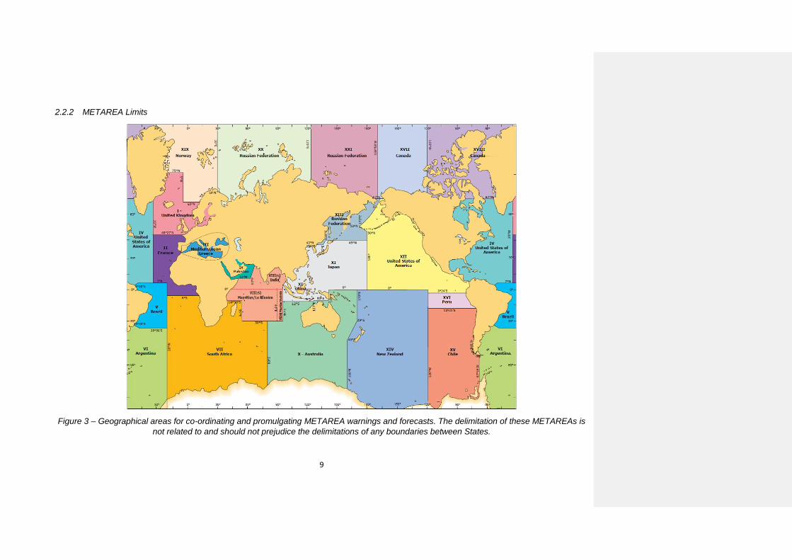
.15 METAREA means a geographical sea area established for the purpose of
coordinating the broadcast of marine meteorological information. The term METAREA
followed by a roman numeral may be used to identify a particular sea area. The
delimitation of such areas is not related to and should not prejudice the delimitation of
any boundaries between States (see figure 3).
.16 METAREA Coordinator means the individual with the authority to coordinate
Marine Meteorological Information broadcasts by one or more National Meteorological
and Hydrological Services acting as Preparation or Issuing Services within the
METAREA.
1 As set out in the IMO NAVTEX Manual.

6
.17 Meteorological information means the marine meteorological warnings and
forecast information in accordance with the provisions of the International Convention
for the Safety of Life at Sea, 1974, as amended.
.18 National Coordinator means the national authority charged with collating and
issuing coastal warnings within a national area of responsibility.
.19 National Enhanced Group Call service means the broadcast and automatic
reception of Maritime Safety Information via the EGC system, using languages as
decided by the Administration concerned.
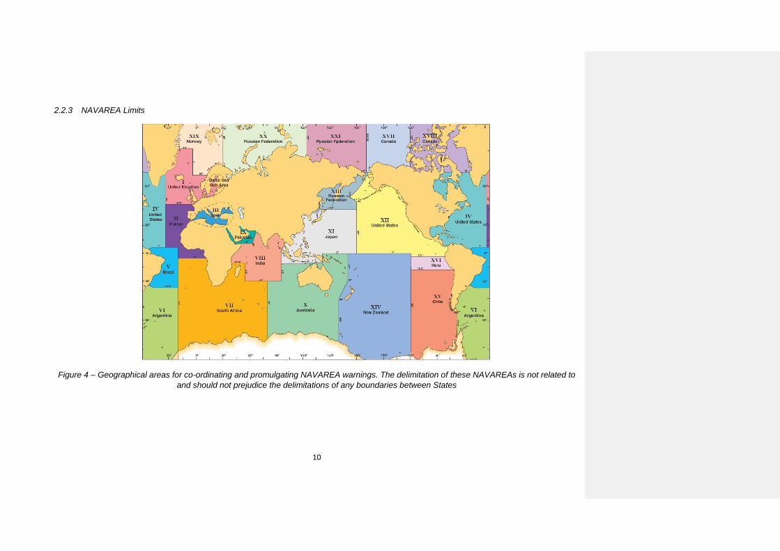
.20 NAVAREA means a geographical sea area established for the purpose of
coordinating the broadcast of navigational warnings. The term NAVAREA followed by
a roman numeral may be used to identify a particular sea area. The delimitation of
such areas is not related to and should not prejudice the delimitation of any boundaries
between States (see figure 4).
.21 NAVAREA Coordinator means the authority charged with coordinating,
collating and issuing NAVAREA warnings for a designated NAVAREA.
.22 NAVAREA warning means a navigational warning or in-force bulletin
promulgated as part of a numbered series by a NAVAREA Coordinator.
.23 Navigational warning means a message containing urgent information relevant
to safe navigation broadcast to ships in accordance with the provisions of the
International Convention for the Safety of Life at Sea, 1974, as amended.
.24 Other urgent safety-related information means Maritime Safety Information
broadcast to ships that is not defined as a navigational warning or meteorological
information. This may include, but is not limited to, significant malfunctions or changes
to maritime communications systems, and new or amended mandatory ship reporting
systems or maritime regulations affecting ships at sea.
.25 Preparation Service means a National Meteorological and Hydrological Service
or National Authority which has accepted responsibility for the preparation of warnings
and forecasts and warnings for parts of or an entire METAREA in the WMO system for
the dissemination of meteorological forecasts to shipping under the GMDSS and for
their transfer to the relevant Issuing Service for broadcast.
.26 Recognized mobile satellite service means any service which operates through
a satellite system and is recognized by IMO for use in the GMDSS.
.27 Registered information provider means a Maritime Safety Information provider
(MSI provider) or a Search and Rescue Information provider, authorized in accordance
with AnnexAppendix 2 of this manual.
.28 Rescue Coordination Centre (RCC) means a unit responsible for promoting
efficient organization of search and rescue services and for coordinating the conduct
of search and rescue operations within a search and rescue region. Note: the term
RCC will be used within this Manual to apply to either joint, aeronautical or maritime
centres; JRCC, ARCC or MRCC will be used as the context warrants.
.29 Search and Rescue (SAR) related information means distress alert relays and
other urgent search and rescue related information broadcast to ships.

7
.30 Satellite Network Operations Center (SNOC) means a terrestrial part of the
Iridium mobile-satellite system which controls the Iridium satellites and manages the
Iridium system overall.
.31 Satellite Ocean Region means the area on the earth's surface within which a
mobile or fixed antenna can obtain line-of-sight communications with one of the four
primary Inmarsat C geostationary satellites. This area may also be referred to as the
"footprint":
- Atlantic Ocean Region – East (AOR-E)
- Atlantic Ocean Region – West (AOR-W)
- Indian Ocean Region (IOR)
- Pacific Ocean Region (POR)
[- Arctic Ocean Region]
The Iridium system is not limited to specific ocean regions therefore the Iridium
SafetyCast equivalent for this would be a global transmission or sending to the Global
Ocean Region. Other “Ocean regions”, such as an Arctic Ocean Region, could also
be created as predefined areas in the Iridium SafetyCast system.
.32 Sea Area A1 means an area within the radiotelephone coverage of at least one
VHF coast station in which continuous DSC alerting is available, as may be defined by
a Contracting Government.
.33 Sea Area A2 means an area, excluding sea area A1, within the radiotelephone
coverage of at least one MF coast station in which continuous DSC alerting is
available, as may be defined by a Contracting Government.
.34 Sea Area A3 means an area, excluding sea areas A1 and A2, within the
coverage of an Inmarsat geostationary satellite in which continuous alerting is
available.
.35 Sea Area A4 means an area outside sea areas A1, A2 and A3.
.36 Ship Earth Station (SES) means a mobile earth station in the recognized
maritime mobile satellite service located on board a ship. This may also be referred to
as Mobile Earth Station or a maritime mobile terminal.2
.37 Sub-Area means a subdivision of a NAVAREA/METAREA in which a number
of countries have established a coordinated system for the promulgation of Maritime
Safety Information. The delimitation of such areas is not related to and should not
prejudice the delimitation of any boundaries between States.
.38 Sub-Area Coordinator means the authority charged with coordinating, collating
and issuing Sub-Area warnings for a designated Sub-Area.
.39 Sub-Area warning means a navigational warning or in-force bulletin
promulgated as part of a numbered series by a Sub-Area Coordinator. Broadcast
should be made by the International NAVTEX service to defined NAVTEX service
2 SES within this document refers to a type approved EGC capable ship earth station
8
areas or by the International Enhanced Group Call service (through the appropriate
NAVAREA Coordinator).
.40 Teleport means a terrestrial part of the Iridium mobile-satellite system which
communicates between the Iridium satellites and the gateway and Satellite Network
Operations Center terrestrial parts.
.41 User-defined area means a temporary geographic area, either circular or
rectangular, to which Maritime Safety Information or Search and Rescue related
information is addressed.
.42 UTC means Coordinated Universal Time which is equivalent to GMT (or ZULU)
as the international time standard.
.43 World-Wide Met-Ocean Information and Warning Service (WWMIWS) means
the internationally coordinated service for the promulgation of meteorological warnings
and forecasts.
.44 World-Wide Navigational Warning Service (WWNWS) means the
internationally and nationally coordinated service for the promulgation of navigational
warnings.
.45 In the operating procedures coordination means that the allocation of the time
for data broadcast is centralized, the format and criteria of data transmissions are
compliant as described in the Joint IMO/IHO/WMO Manual on Maritime Safety
Information and that all services are managed as set out in resolutions A.705(17), as
amended, A.706(17), as amended, and A.1051(27), as amended.
9
2.2.2 METAREA Limits
Figure 3 – Geographical areas for co-ordinating and promulgating METAREA warnings and forecasts. The delimitation of these METAREAs is
not related to and should not prejudice the delimitations of any boundaries between States.
10
2.2.3 NAVAREA Limits
Figure 4 – Geographical areas for co-ordinating and promulgating NAVAREA warnings. The delimitation of these NAVAREAs is not related to
and should not prejudice the delimitations of any boundaries between States

11
3 General features of the Iridium Global Satellite EGC SafetyCast service
3.1 All navigable waters of the world are covered by satellites in the Iridium global satellite
service. Reception of EGC Iridium SafetyCast messages is normally not affected by the
position of the ship, atmospheric conditions or time of day.
3.2 Area calls are addressed to a geographical area, whereas group calls are addressed
to groups of ships:
.1 Area calls can be addressed to a fixed geographical area (NAVAREA/METAREA or
coastal warning area) or to a user-defined area selected by an information provider. Area calls
will be received automatically by any Iridium EGC SafetyCast receiver within the area. To
receive coastal warnings, the EGC Iridium SafetyCast receiver must be set up with appropriate
coastal warning codes. (see section 12.3). Ocean Regions can also be predefined as fixed
geographical areas in the Iridium system, where the registered information provider requires
this.
.2 Group calls will be received automatically by any ship whose EGC Iridium
SafetyCast receiver acknowledges the unique group identity associated with a particular
message.
3.3 The Iridium network enables the promulgation of Maritime Safety Information (MSI),
SAR related information and other urgent safety related messages to vessels. Messages are
initiated via a secure, web-based portal that Iridium will make available to MSI/SAR information
providers (see example in Annex Appendix 3 below), or by such other means of access as
may be agreed to. Using the portal registered information providers will input the text of the
message and specify the delivery characteristics for each message. The delivery
characteristics that the registered information providers specify include message priority,
geographic region for distribution, frequency of distribution, and termination of distribution, if
applicable.
3.4 Registered information providers may elect to have a direct connection to the Iridium
gateway using a VPN or dedicated circuit(s). Utilizing this interface, the message priority,
delivery area, frequency of distribution and termination of distribution are specified by the
message originator when the message is sent to the Iridium Safety Gateway for delivery.
3.5 Each message is queued at a server in the Iridium Safety Gateway and scheduled for
delivery. When queued for delivery, the message is routed to the appropriate teleport(s) for
delivery to the satellite(s). The message is then routed from the teleport to one, or more,
satellite(s) depending on the geographic region for distribution. The satellite then utilizes an
L-band channel to transmit the message to Iridium maritime mobile terminals. If specified by
the registered information provider initiating the message, retransmission of the message is
performed at specified time intervals for the geographic area. A flow diagram for shore-to-ship
promulgation of Iridium EGC SafetyCast messages is provided in Figures 1 and 2 above.
3.6 Unique geographic areas are defined for each NAVAREA/METAREA, and for Coastal
areas. The delivery area for the messages is defined by a set of coordinates which provides
the boundary of the delivery area. The delivery area for each NAVAREA/METAREA will extend
from the coastline of each of the regions to 300 nautical miles beyond the line of demarcation
with an adjacent NAVAREA/METAREA. This will permit maritime mobile terminals outside of
a NAVAREA/METAREA to receive a message in the adjacent region if it is within 300 nautical
miles of that NAVAREA/METAREA boundary.
12
3.7 Registered information providers have the ability to establish a user-defined area for a
message, to include circular or rectangular area addressing.
3.8 Aboard the vessel, the Iridium SES should be interconnected to a message display
and alarm panel that will perform the proper filtering, recording, alerting and display of
messages. Additionally a SES may have a keyboard and printer. The SES will receive the
message, and then transfer the message content, along with the message priority to the other
components of the GMDSS system on board the vessel.
4 Planning of new Iridium EGC SafetyCast services
4.1 Authorities wishing to become officially registered information providers of MSI and
SAR related information to ships at sea via Iridium EGC SafetyCast services, should contact
the IMO via the IMO EGC Coordinating Panel at an early stage for advice. The plans of any
prospective registered information providers should be coordinated with the IMO, IHO and
WMO and with other national authorities, before authorization to broadcast via Iridium EGC
SSafetyCast services may be granted by the IMO EGC Coordinating Panel, in accordance
with the procedures set out in Annex Appendix 2.
4.2 Once authorized and registered, information providers should contact Iridium in order
to determine specific details for addressing messages, accessing the Iridium SafetyCast
services, charges and payment for services and any other matters with respect to providing
MSI and SAR related information to mariners.
4.3 The IMO EGC Coordinating Panel, in cooperation with IHO and WMO, undertakes the
coordination of times for scheduled transmissions.
4.4 Mariners should be informed of the establishment of an Iridium SafetyCast service by
the information provider through the inclusion of full details in Notices to Mariners and other
national nautical publications and the IMO Master Plan of Shore-Based Facilities for the
GMDSS, as amended. In addition, full details of the service should be sent to the IMO EGC
Coordinating Panel at the address given in Annex Appendix 1.
4.5 Questions concerning promulgation of MSI and SAR related information through the
Iridium EGC SafetyCast service can be addressed to the IMO EGC Coordinating Panel at the
address given in Annex Appendix 1.
4.6 Questions concerning the operation of the Iridium EGC SafetyCast service should be
addressed to:
Maritime Safety Services
Iridium Satellite LLC
1750 Tysons Boulevard, Suite 1400
McLean, VA
22102 USA
E-mail address: [email protected]
Field Code Changed

13
5 Changes to existing Iridium EGC SafetyCast services
5.1 Registered information providers wishing to change their existing service should follow
the same coordination procedures as for a new service, in accordance with the procedures
set out in Annex Appendix 2.
5.2 Mariners should be informed of the changes to an existing service by the information
provider through the inclusion of full details in Notices to Mariners and other national nautical
publications and the IMO Master Plan of Shore-Based Facilities for the GMDSS, as amended.
In addition, full details of the service should be sent to the IMO EGC Coordinating Panel at the
address given in Annex Appendix 1.
6 Operation of the Iridium EGC SafetyCast service
6.1 Given the size of a sea area, some form of selectivity in receiving and printing the
various messages is required. All ships within the geographically defined area of the broadcast
will receive area calls, however, they will only be displayed and printed by those receivers that
recognize both:
.1 the fixed geographical area (NAVAREA/METAREA), user-defined area as
appropriate; and
.2 for coastal warnings, the coastal warning area and the subject indicator for the
message.
6.2 The message format includes an instruction which enables the SES to display and
print only those messages which relate to its present position, to the intended route, or to the
aforementioned areas as programmed by the operator.
6.3 For coastal warning areas messages, the registered information provider must ensure
that the preamble includes the identifier allocated for the particular area, along with the
appropriate subject indicator (see section 12.3). The Iridium SES can be set to reject
messages concerning certain optional subjects which may not be required by the ship. The
Iridium SES also uses the subject indicator to identify coastal warnings which, because of their
importance, may NOT be rejected.
6.4 Reception of certain types of messages, such as shore-to-ship distress alerts, SAR
related information, meteorological warnings and forecasts and navigational warnings,
addressed to a geographical area within which the Iridium SES is located, is mandatory and
cannot be suppressed by ships in the affected area.
When a message has been received error-free, a record is made of the message identification
(the unique sequence number, the unique identifier and the service code) associated with that
message. The unique sequence number is used to suppress the printing of repeated
transmissions of the same message.
6.5 The Iridium EGC SafetyCast service allows several input parameters to support MSI
and SAR related information transmissions:
.1 Fixed geographical area (NAVAREA/METAREA) or user defined area/ areas
.2 Message Priority (Distress, Urgency, Safety and Routine)
.3 Delivery Method (Immediate or Scheduled)
.4 Echo (Up to 2 times)

14
.5 Repeat (Number of Instances)
.6 Scheduled transmissions may be cancelled by notifying the service
6.6 There are three methods of identifying the destination delivery area for an Iridium EGC
SafetyCast transmission, including pre-defined areas such as NAVAREA/METAREAs, sub-
areas and coastal areas, or user-defined areas.
6.7 Messages can be addressed to user-defined areas, which may be circular or
rectangular in shape. A circular area is described by latitude and longitude of the centre in
degrees and radius of the circle in nautical miles. A rectangular area is described by latitude
and longitude of the south-west corner in degrees and extension in degrees to the north and
east of the rectangle. Each satellite has a footprint of approximately 4,500 km diameter, and
comprises 48 spot beams of approximately 400 km diameter. Each beam within a footprint
overlaps, as do the beams from adjacent satellites. The Iridium system dynamically uses the
most appropriate combination of beams and satellites for the delivery area required.
Formatted: Font:

15
Figure 5 – Examples of message addressing
6.8 In the case of a ship in distress, it is normal to create a circular user-defined area,
defined by the position of the casualty and a radius around the casualty to alert ships that may
be able to render assistance. If no response is received from any ship at the first call, the area
can be expanded in steps until an acknowledgement by one or more ships is received. In
cases where the position of the distress is unknown, a shore-to-ship distress alert relay can
be transmitted to all ships, in a given sea area. SAR related information should only be
addressed to circular or to rectangular user-defined areas.
7 Promulgation of Maritime Safety Information (MSI) or Search and Rescue (SAR)
related Information
7.1 MSI or SAR related information is promulgated by registered information providers
whose Certificates of Authorization to promulgate via Iridium are issued by the IMO Enhanced
Group Call Coordinating Panel in accordance with the procedures in Annex Appendix 2.
Registered information providers include for example:
.1 NAVAREA Coordinators: for navigational warnings and other urgent safety-
related information;
.2 National Coordinators: for coastal warnings and other urgent safety-related
information;
.3 METAREA Coordinators: for meteorological warnings and forecasts; and
.4 Rescue Coordination Centres: for shore-to-ship distress alert relay, SAR
related information and other urgent safety-related information.
7.2 All NAVAREA, Sub-Area and coastal warnings and METAREA warnings and forecasts
should be promulgated only in English in the Iridium EGC SafetyCast service in accordance
Formatted: Font: (Default) Arial
16
with resolution A.706(17), as amended, and A.1051(27) as amended. In addition to the
required broadcasts in English, NAVAREA/METAREA, Sub-Area and coastal warnings may
be broadcast in a national language using a national Iridium EGC SafetyCast service.
7.3 Registered information providers should take into account the need for contingency
planning.
7.4 Scheduled transmissions are made at specified times, as allocated by the IMO EGC
Coordinating Panel. These schedules are published in national nautical publications and the
IMO Master Plan of Shore-Based facilities for the GMDSS, as amended.
7.5 MSI providers should adhere to their published scheduled broadcast times to facilitate
reception of messages.
8 Message formatting and C codes
8.1 The Iridium global satellite EGC SafetyCast service does not require registered
providers manually to enter transmission instructions using C codes, although some registered
providers may have an operational requirement to use these. For those users who have a
continuing operational requirement to use C Codes, Annex Appendix 4, Part 2 of this manual
is provided .
8.2 There are several methods for registered providers to gain access to the Iridium EGC
SafetyCast service, and these are described in section 10 and Annex Appendix 3. These
include a secure user portal which enables authorized users to send and cancel messages.
Detailed operational procedures are contained in the instructions given to registered providers
after authorization and registration in accordance with Annex Appendix 2. The Iridium
SafetyCast service automatically formats the message and its transmission instructions.
9 Monitoring of MSI and SAR related broadcasts
(Monitoring of MSI and SAR related broadcast in a multi provider environment is
currently under discussion within the relevant IMO/IHO/WMO MSI and SAR bodies.)
9.1 In order to ensure the integrity of the MSI and SAR related messages being broadcast,
MSI and SAR providers must monitor the broadcasts which they originate in accordance to
resolutions A.706(17), A.1051(27) as amended and COMSAR/Circ.37. Monitoring is
especially important in a highly automated service, which is dependent on careful adherence
to procedure and format. This shall be accomplished by a service that shall provide the means
to enable each MSI and SAR information provider to:
.1 confirm that the message is transmitted and received correctly;
.2 ensure that cancellation messages are properly executed; and
.3 observe any unexplained delay in the message being broadcast.
9.2 This service shares responsibility for monitoring broadcast between the registered
information provider, and the Iridium EGC SafetyCast service so that the registered
information provider is responsible for ensuring their messages are correct before they submit
their message to the EGC Iridium SafetyCast service for delivery, and the EGC Iridium
SafetyCast service ensures that messages are broadcast correctly, as received.
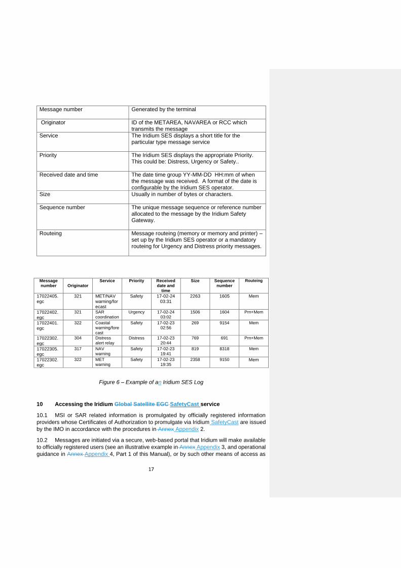
9.3 The Iridium SES maintains a Log, which contains information on all messages received
by the terminal.
This information within the Log includes:
17
Message number
Generated by the terminal
Originator
ID of the METAREA, NAVAREA or RCC which transmits the message
Service
The Iridium SES displays a short title for the particular type message service
Priority
The Iridium SES displays the appropriate Priority. This could be: Distress, Urgency or Safety..
Received date and time
The date time group YY-MM-DD HH:mm of when the message was received. A format of the date is configurable by the Iridium SES operator.
Size
Usually in number of bytes or characters.
Sequence number
The unique message sequence or reference number allocated to the message by the Iridium Safety Gateway.
Routeing
Message routeing (memory or memory and printer) – set up by the Iridium SES operator or a mandatory routeing for Urgency and Distress priority messages.
Message number
Originator
Service Priority Received date and
time
Size Sequence number
Routeing
17022405.egc
321 MET/NAV warning/forecast
Safety 17-02-24 03:31
2263 1605 Mem
17022402.egc
321 SAR coordination
Urgency 17-02-24 03:02
1506 1604 Prn+Mem
17022401.egc
322 Coastal warning/forecast
Safety 17-02-23 02:56
269 9154 Mem
17022302.egc
304 Distress alert relay
Distress 17-02-23 20:44
769 691 Prn+Mem
17022305.egc
317 NAV warning
Safety 17-02-23 19:41
819 8318 Mem
17022302.egc
322 MET warning
Safety 17-02-23 19:35
2358 9150 Mem
Figure 6 – Example of an Iridium SES Log
10 Accessing the Iridium Global Satellite EGC SafetyCast service
10.1 MSI or SAR related information is promulgated by officially registered information
providers whose Certificates of Authorization to promulgate via Iridium SafetyCast are issued
by the IMO in accordance with the procedures in Annex Appendix 2.
10.2 Messages are initiated via a secure, web-based portal that Iridium will make available
to officially registered users (see an illustrative example in Annex Appendix 3, and operational
guidance in Annex Appendix 4, Part 1 of this Manual), or by such other means of access as
18
may be agreed. Using the portal, users will input the text of the message and specify the
delivery characteristics for each message. The delivery characteristics that the users specify
include message priority, geographic region for broadcast, frequency of broadcast, and
cancellation of broadcast. Messages can also be manually cancelled.
10.3 Users may elect to have a direct connection to the Iridium gateway using a VPN or
dedicated circuit(s). Utilizing this interface, the message priority, delivery area, frequency of
broadcast and cancellation of broadcast are specified by the message originator when the
message is sent to the Iridium Safety Gateway for delivery.
11 Iridium Safety Gateway functions
Each message is queued at a server in the Iridium Safety Gateway and scheduled for
broadcast. When queued for broadcast, the message is routed to the appropriate teleport(s)
for broadcast to the satellite(s). The message is then routed from the teleport to one, or more
satellite(s) depending on the geographic region for broadcast.
12 Receiving transmission
12.1 When a message has been received, a record is made of the message
identification associated with that message. The unique sequence number is used to suppress
the printing of repeated transmissions of the same message. The Iridium GMDSS SafetyCast
system tracks the transmission and receipt of MSI broadcasts for each ship in the targeted
area. The Iridium GMDSS SafetyCast system filters messages that have already been
received by the Iridium SESs in the area targeted by the registered information provider. This
eliminates the need for the SES to suppress a message once it has received the message the
first time.
12.2 The Iridium SES also suppresses the printing of messages previously received. It is
not possible to reject mandatory "all ship" messages such as shore-to-ship distress alert relays
for the area within which the ship is located. When a distress or urgency message is received,
an audio and visual alarm will be given.
12.3 The following subject indicators for coastal warnings are in use3:
A = Navigational warnings
B = Meteorological warnings
C = Ice reports
D = Search and rescue related information, and acts of piracy warnings
E = Meteorological forecasts
F = Pilot service messages
G = AIS
H = Not used
I = Not used
J = SATNAV messages
K = Other navaid messages
3 Cannot be rejected by the receiver

19
L = Other navigational warnings – additional to subject code A
V = Special services allocation by the IMO EGC Coordinating Panel
W = Special services allocation by the IMO EGC Coordinating Panel
X = Special services allocation by the IMO EGC Coordinating Panel
Y = Special services allocation by the IMO EGC Coordinating Panel
Z = No messages on hand
12.4 It is recommended that, in order to ensure that all necessary MSI is available before
sailing, the Iridium SES should remain in operation while the ship is in port. When the SES is
switched on and logged onto the Iridium GMDSS SafetyCast system it will automatically
receive in-force messages.
12.5 Although reception of MSI and SAR related information is automatic, the shipboard
operator must set up the Iridium SES properly before the start of the voyage, in accordance
with the manufacturer’s instructions.
12.6 The position information in Iridium SES is up-dated automatically from integrated
navigational receivers and these are fitted on all Iridium SES, or may be up-dated from a
separate electronic position-fixing system.
13 Charges for MSI services
13.1 Resolution A.707(17): Charges for Distress, Urgency and Safety Messages Through
the Inmarsat System, establishes the arrangements in place for the treatment of charges. IMO
resolution A.1001(25). Criteria for the provision of mobile satellite communication systems in
the Global Maritime Distress and Safety System (GMDSS), requires that prospective satellite
systems operating in the GMDSS undertake to apply the principles of resolution A.707(17),
and Iridium has given such an undertaking.
13.2 There are no charges to the mariner for reception of these messages.
13.3 Message transmission charges apply to MSI providers and are set at a special tariff.

20
Annex Appendix 1
IMO Enhanced Group Call Coordinating Panel
1 Terms of reference To coordinate the development and use of the International Enhanced Group Call (EGC) services, and in particular to:
.1 develop operating methods for the effective use of the EGC services, including consideration of the need for scheduled broadcasts;
.2 develop documentation in support of EGC services, in particular the IMO
manuals of the recognized mobile satellite service providers;
.3 advise recognized mobile satellite service providers and potential registered information providers on all aspects of the EGC services, including system access and effective operation;
.4 develop criteria and establish means for the approval and registration of
potential information providers to ensure world-wide coverage is achieved and maintained;
.5 coordinate the registration of potential information providers; and
.6 promote a proper understanding of the benefits and use of the EGC services
amongst the wider maritime community. 2 Contact address The IMO Enhanced Group Call Coordinating Panel can be contacted at the following address:
The Chair IMO Enhanced Group Call Coordinating Panel International Maritime Organization 4 Albert Embankment London SE1 7SR United Kingdom Telephone: +44 (0)20 7735 7611, Fax: +44 (0)20 7587 3210 e-mail: [email protected] (in subject line add: for Chair, IMO Enhanced Group Call Coordinating Panel)
3 Panel membership 3.1 The IMO Enhanced Group Call Coordinating Panel is open to membership by all Member Governments and also includes one member nominated by each of the following international organizations:
.1 International Maritime Organization (IMO)
.2 International Hydrographic Organization (IHO)
.3 World Meteorological Organization (WMO)
21
.4 International Mobile Satellite Organization (IMSO)
3.2 The following may be represented as observers on the panel:
.1 IHO World-Wide Navigational Warning Service Sub-Committee
.2 IMO NAVTEX Coordinating Panel
.3 WMO World-Wide Met-Ocean Information and Warning Service Committee (WWMIWS-C) of the Joint WMO-IOC Technical Commission for Oceanography and Marine Meteorology (JCOMM)
.4 Single representative from each recognized mobile satellite service provider

22
Annex Appendix 2
Authorization, certification and registration of Enhanced Group Call information providers
Two distinct and separate processes, Authorization and Certification, must be completed before an information provider will be granted Registration to access the International Enhanced Group Call (EGC) service. They have been established to protect the integrity of the EGC information service and clearly establish a qualification to the special EGC tariff. 1 Authorization 1.1 Authorization is carried out by IMO in consultation with IHO and WMO as appropriate. 1.2 In order to obtain authorization to broadcast Maritime Safety Information and/or Search and Rescue related information through the International Enhanced Group Call service, an information provider should apply to the relevant international organization for approval to participate in the internationally coordinated service:
Hydrographic authorities – to IHO; Meteorological authorities – to WMO; Search and rescue authorities – to IMO; The International Ice Patrol – to IMO; Others – to IMO.
1.3 In considering such applications, the relevant international organizations will take into account:
.1 the established and expected availability of other information sources for the
area concerned; and .2 the need to minimize duplication of information as much as possible.
1.4 The relevant international organization will inform IMO of endorsed applications. 2 Certification 2.1 On receipt of IMO authorization, the IMO International Enhanced Group Call Coordinating Panel will issue a Certificate of authorization to participate in the International Enhanced Group Call service directly to the information provider with a copy to IMO or IHO or WMO, as well as to all recognized mobile satellite service providers concerned. A specimen Certificate of Authorization is shown at the end of this appendix. 2.2 IMO International Enhanced Group Call Coordinating Panel will maintain the master list of all registered information providers and circulate it to IMO, IHO and WMO Secretariats and all recognized mobile satellite service providers concerned.

23
3 Registration
3.1 After receiving a Certificate of Authorization, an information provider should conclude an agreement with all recognized mobile satellite service providers concerned, serving the required sea area(s), to obtain access to the system. 3.2 This will involve, in addition to the contractual aspects, registration of the information provider's identity which should be programmed into the control equipment of the recognized mobile satellite service provider. 3.3 Recognized mobile satellite service providers will only register information providers who have received a Certificate of Authorization from the IMO International Enhanced Group Call Coordinating Panel. 4 Contact addresses
International Maritime Organization The Chair International Enhanced Group Call Coordinating Panel 4 Albert Embankment London SE1 7SR United Kingdom Telephone: +44 (0)20 7735 7611 Fax: +44 (0)20 7587 3210 Email: [email protected] (in subject line add: for Chair, IMO International Enhanced Group Call Coordinating Panel)
International Hydrographic Organization 4b quai Antoine 1er BP445 MC98011 Monaco Cedex Principauté de MONACO
Telephone: +377 93 10 81 00 Fax: +377 93 10 81 40
Email: [email protected]
World Meteorological Organization 7bis, avenue de la Paix Case postale 2300 CH-1211 Geneva 2 Switzerland Telephone: + 41(0) 22 730 81 11 Fax: + 41(0) 22 730 81 81 Email: [email protected]

24
5 Sample Certificate of Authorization
[Sample to be developed.]

25
Annex Appendix 3
The Iridium Global Mobile-Satellite System
1 Introduction
1.1 Iridium Satellite LLC owns and operates a Global Mobile Personal Communications
by Satellite (GMPCS) system providing fully global digital communications. The major
components of the Iridium mobile-satellite system are:
1.1.1 The space segment, consisting of 66 operational satellites and additional in-orbit spare
satellites;
1.1.2 The ground segment, consisting of satellite teleports (“teleports”) for the transfer of
voice and data communications between the gateways and the satellite constellation, and
gateways which provide connection to terrestrial voice and data networks; and
1.1.3 Mobile earth stations, which consist of a satellite modem, which is incorporated into a
commercial product, and an externally installed antenna.
1.2 The satellite constellation provides the communication links between the user
terminals and the teleport(s), which are interconnected to the gateways. The gateways serve
as the switching center, routing all communications into and from terrestrial networks, such as
the PSTN. The gateway also locates, identifies and tracks subscribers for mobility
management, and records user activity for billing purposes.
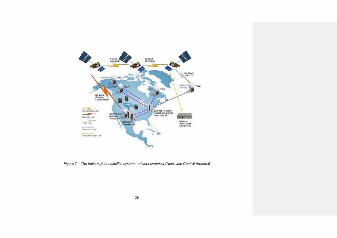
1.3 These components are illustrated in Figure 7 below:
26
Figure 7 – The Iridium global satellite system, network overview (North and Central America)

27
2 The space segment
2.1 The constellation of 66 operational Low Earth Orbit (LEO) satellites enables user
terminal-to-user terminal, user terminal-to-gateway, and gateway-to-user terminal
communications. The 66 satellites are evenly distributed in six orbital planes with a polar
(86.4 degree) inclination, with on-orbit spare satellites. The satellites orbit the Earth at an
altitude of 780 km and take approximately 100 minutes to complete one orbit.
Figure 8 - Iridium constellation,
Formatted: Font: (Default) Arial
Formatted: Font: (Default) Arial

28
2.2 The satellites support three types of communication links – satellite-to-satellite,
satellite-to-teleport, and satellite-to-user terminal. Each satellite communicates with the
satellite immediately ahead and behind in its orbital plane (north/south) and to the nearest
satellite in each of the two adjacent orbital planes (east/west) using a K-band link. The Iridium
system is the only mobile-satellite system employing this cross-linked satellite architecture. As
a result, a user terminal is not required to be within the same satellite footprint as a gateway
in order to gain access to the network.
2.3 The satellite-to-user terminal link uses an L-band antenna system. This projects 48
spot beams, or cells, on the Earth, with each beam being approximately 400 km (250 miles)
in diameter. Each L-band antenna has a “footprint” with a diameter of approximately 4,500 km
(2,800 miles). Adjacent satellite footprints overlap on the Earth’s surface, enabling seamless
global coverage from pole to pole. The overlapping coverage provided by the cross-linked
satellites operates as a fully meshed network.
2.4 About once every minute, the cell for a user terminal is provided by a different beam
on the same satellite. About once every six minutes, the cell transitions to a beam on an
adjacent satellite. Special processing called a “handoff” ensures that communication sessions
are maintained.
3 The ground segment
3.1 The Satellite Network Operations Center (SNOC) manages the satellite constellation
and provides network management over the entire Iridium system. The SNOC communicates
with the satellites through Telemetry, Tracking and Control (TTAC) facilities. In addition to
controlling communications between the SNOC and the satellites, the TTAC sites track the
Iridium satellites and receive telemetry data from them.
3.2 Iridium currently operates teleports at geographically diverse locations around the
globe, as part of the commercial network. The teleports use a Ka-band link to interconnect the
satellite constellation with the Iridium gateways for the transfer of communications to and from
Iridium user terminals.
3.3 Operating as a switching center, the primary gateway provides the connection between
the Iridium network and terrestrial-based networks. Additional gateways are being added
around the globe, where appropriate, which can serve to enhance overall system reliability
and capacity. Each gateway controls system access, call setup, mobility management, billing,
tracking and maintaining all information pertaining to user terminals, such as user identity and
geo-location.
4 Coverage Area
The Iridium network provides fully global service coverage. All communication services are
provided for user terminals independent of geographic location. Communications are provided
by a constellation of LEO satellites with overlapping coverage areas, providing ubiquitous
coverage. The Iridium network and the services that are intended to be used for GMDSS
communications are fully operational for the entire globe.
5 Iridium Network Functional Capabilities
5.1 The Iridium network permits ship-to-shore, shore-to-ship and ship-to-ship calls for
maritime safety communications. It provides for four levels of prioritization of all calls and
performs pre-emption of lower priority communications, if necessary.

29
5.2 Only registered information providers will be allowed to input messages for broadcast.
Approval and registration of these entities is performed by the IMO EGC Coordinating Panel
by the procedure described in Annex Appendix 2 of this Manual. During the approval and
registration process, the means of access, and the credentials needed by the authorised
entity, will be provided by the IMO EGC Coordinating Panel and Iridium. It is necessary to
ensure that the prioritisation of traffic is protected against inadvertent or malicious misuse. For
example, access can be protected by requiring a two-stage access procedure using a
password and PIN, and these could be combined into other functions where a registered
information provider had existing alternative operational security measures in place.
authorised users Registered information providers can input messages using email, a web
interface or other means of transmitting data over the Internet, a leased line or VPN, according
to their operational requirements.. One such method is a secure portal provided by Iridium, a
development version of which has been made available for testing and is subject to further
refinement. Operational guidance for the use of the development portal is given in Annex
Appendix 4 Part 1 of this manual. The graphical user interface (GUI) of the portal used in
development is shown below:
Figure 9a – Legacy example of information provider input screen. Input screen is currently
under development and may be subject to further refinement.

30
Figure 9b – Continued legacy example of information provider input screen. Input screen is
currently under development and may be subject to further refinement.
Figure 10 - System receipt screen (illustrative example currently used for testing and
development, and which may be subject to further refinement)
5.3 Transmission of safety-related information by ships to shore authorities is
accomplished using the general communication capabilities of the Iridium system. Messages
can be addressed to relevant shore authorities (hydrographic offices, meteorological offices
or other shore authorities) using the contact details published in Lists of Radio Signals and
elsewhere.
6 Network Availability and Service Restoration
31
6.1 The Iridium network provides all services globally and is in continuous
operation. System performance for each of the services is continuously monitored worldwide
through numerous mechanisms. If there is a service impairment, Iridium will issue an advisory
notice within ten minutes of the impairment being identified by operations staff, and provide
regular updates until the impairment is corrected. In the event of a partial or total satellite
failure, services to affected users will be fully restored within minutes. The constellation
architecture and operation does not permit a single satellite to cause an extended service
interruption from the user’s perspective. The nature of the satellite footprints as they orbit,
combined with “echo” transmissions, ensures that ships will still be able to transmit distress
alerts and to receive MSI or SAR related information even in the event of a satellite failure.
6.2 The International Mobile Satellite Organization (IMSO) will provide annual reports to
the IMO on Iridium’s performance of its GMDSS functions, including availability during the
reporting period.

32
Annex Appendix 4
Operational guidance – Part 1
For those registered information providers who require it, Iridium provides a secure online
portal (with graphical user interface or GUI) for accessing the Iridium [NAME] SafetyCast
service. Part 1 of this appendix contains operational guidance for the benefit of registered
information providers who are responsible for preparing messages for broadcast. It also
contains operational guidance for SAR authorities authorised to use the Iridium
[NAME]SafetyCast service.
For those registered information providers who require it, for example those who use tailor-
made operational management systems, or whose messages are generated by highly
automated (machine-to-machine) processes, Iridium will make available an application
programming interface (API) to enable access to the Iridium [NAME]SafetyCast service.
Credentials
Only registered information providers will have access to the Iridium [NAME]SafetyCast
service. The procedure for authorization and certification of registered information providers
is described in Appendix 2 of this Manual. These registered information providers will be
provided with credentials for access to the Iridium [NAME]SafetyCast service. These
credentials will identify the registered information provider to the service, and will also
determine which types of message that registered information provider can send.
Message Type
METAREA Coordinators can select “Forecasts and warnings”, “Tropical cyclone warning” or
“Other safety-related information” and can also select whether to send the message to the
METAREA, a coastal area (if applicable) or to a user-defined area.
NAVAREA Coordinators can select “Navigational warnings” or “Other safety-related
information” and can also select whether to send the message to the NAVAREA, a coastal
area (if applicable) or to a user-defined area.
SAR Authorities can select “Distress alert relay” or “SAR Coordination”. SAR Authorities
default to user-defined areas, although predefined areas could be configured during
integration if this was required. A distress alert relay is normally sent to a circular area.
Message Priority
METAREA and NAVAREA Coordinators can select either “Safety” or “Urgency”.
SAR Authorities can select either “Safety”, “Urgency” or “Distress”, whichever is appropriate
to the emergency phase of the situation. A distress alert relay will be “Distress”.
Although the service permits “Routine” priority, this is unlikely to be an appropriate priority for
use by registered information providers.
Message Delivery Address
Delivery addresses can be predefined or user-defined.
Predefined addresses can include METAREA, NAVAREA, coastal warning area, or another
specific fixed delivery area if required. These areas are created during the integration of the
registered information provider with the Iridium [NAME]SafetyCast service.
33
User-defined addresses are either a circular area or a rectangular area. These can be
determined by the user for a particular message.
Where the message type is for delivery to a METAREA or NAVAREA this will be automatically
completed.
Where the message type is for a coastal warning area or another specific fixed delivery area,
the user selects that area from their particular list of predefined areas. The user also selects
the message subject.
Where the message type is for delivery to a circular area, the user defines that area with the
latitude and longitude of its centre, and its radius in nautical miles.
Where the message type is for delivery to a rectangular area, the user defines that area with
the latitude and longitude of its southwestern corner, and its extent north and east from that
point, in degrees.
Scheduling, Repetition and Cancellation
“Urgent” messages will be queued automatically for immediate transmission followed by
retransmission at the next scheduled transmission time. “Scheduled” messages will be
transmitted according to the schedule determined by the IMO EGC Coordinating Panel.
It is possible to select an “Echo” retransmission (0, 1 or 2) at six-minute intervals, or a
registered information provider may opt to set a definite number of retransmissions and their
intervals. Establishing and configuring this facility will form part of the process of integration
of the registered information provider with the Iridium {NAME]SafetyCast service.
Associated cancellation procedures will also form part of the process of integration of the
registered information provider with the Iridium {NAME]SafetyCast service.
Message Text
The message should be composed according to the detailed guidance given in the Joint
IMO/IHO/WMO Manual on Maritime Safety Information.
Additional Guidance
Additional guidance for METAREA Coordinators is contained in IMO resolution A.1051(27),
as amended, on the Worldwide Met-Ocean Information and Warning Service.
Additional guidance for NAVAREA Coordinators is contained in IMO resolution A.706(17), as
amended, on the World-Wide Navigational Warning Service.
Additional guidance for SAR Authorities is contained in the IAMSAR Manual, volumes I and II.
Additional guidance on piracy countermeasures is contained in resolution MSC.305(87),
Guidelines on operational procedures for the promulgation of maritime safety information
concerning acts of piracy and piracy counter-measure operations.
For those authorized users who require it, Iridium provides a secure online portal for accessing
the EGC service. Part 1 of this annex contains operational guidance for the benefit of
registered MSI providers who are responsible for preparing messages for broadcast:
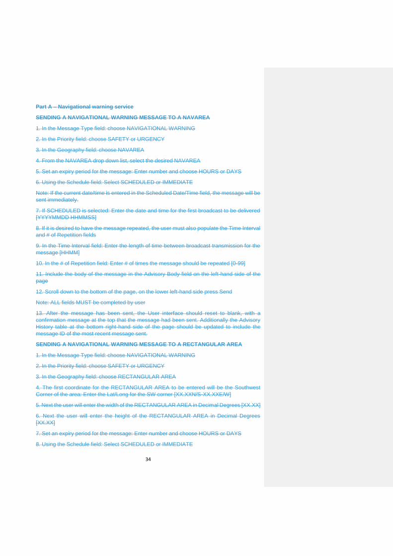
Part A – Navigational warning service
Part B – Meteorological services
Part C – Search and rescue (SAR) services and SAR coordination traffic
34
Part A – Navigational warning service
SENDING A NAVIGATIONAL WARNING MESSAGE TO A NAVAREA
1. In the Message Type field: choose NAVIGATIONAL WARNING
2. In the Priority field: choose SAFETY or URGENCY
3. In the Geography field: choose NAVAREA
4. From the NAVAREA drop down list, select the desired NAVAREA
5. Set an expiry period for the message: Enter number and choose HOURS or DAYS
6. Using the Schedule field: Select SCHEDULED or IMMEDIATE
Note: If the current date/time is entered in the Scheduled Date/Time field, the message will be
sent immediately.
7. If SCHEDULED is selected: Enter the date and time for the first broadcast to be delivered
[YYYYMMDD HHMMSS]
8. If it is desired to have the message repeated, the user must also populate the Time Interval
and # of Repetition fields
9. In the Time Interval field: Enter the length of time between broadcast transmission for the
message [HHMM]
10. In the # of Repetition field: Enter # of times the message should be repeated [0-99]
11. Include the body of the message in the Advisory Body field on the left-hand side of the
page
12. Scroll down to the bottom of the page, on the lower left-hand side press Send
Note: ALL fields MUST be completed by user
13. After the message has been sent, the User interface should reset to blank, with a
confirmation message at the top that the message had been sent. Additionally the Advisory
History table at the bottom right-hand side of the page should be updated to include the
message ID of the most recent message sent.
SENDING A NAVIGATIONAL WARNING MESSAGE TO A RECTANGULAR AREA
1. In the Message Type field: choose NAVIGATIONAL WARNING
2. In the Priority field: choose SAFETY or URGENCY
3. In the Geography field: choose RECTANGULAR AREA
4. The first coordinate for the RECTANGULAR AREA to be entered will be the Southwest
Corner of the area: Enter the Lat/Long for the SW corner [XX.XXN/S-XX.XXE/W]
5. Next the user will enter the width of the RECTANGULAR AREA in Decimal Degrees [XX.XX]
6. Next the user will enter the height of the RECTANGULAR AREA in Decimal Degrees
[XX.XX]
7. Set an expiry period for the message: Enter number and choose HOURS or DAYS
8. Using the Schedule field: Select SCHEDULED or IMMEDIATE

35
Note: If the current date/time is entered in the Scheduled Date/Time field, the message will be
sent immediately.
9. If SCHEDULED is selected: Enter the date and time for the first broadcast to be delivered
[YYYYMMDD HHMMSS]
10. If it is desired to have the message repeated, the user must also populate the Time Interval
and # of Repetition fields
11. In the Time Interval field: Enter the length of time between broadcast transmission for the
message [HHMM]
12. In the # of Repetition field: Enter # of times the message should be repeated [0-99]
13. Include the body of the message in the Advisory Body field on the left-hand side of the
page
14. Scroll down to the bottom of the page, on the lower left-hand side press Send
Note: ALL fields MUST be completed by user
15. The User interface should rest to blank, with a confirmation message at the top that the
message had been sent. Additionally the Advisory History table at the bottom right-hand side
of the page should be updated to include the message ID of the most recent message sent.
SENDING A NAVIGATIONAL WARNING MESSAGE TO A CIRCULAR AREA
1. In the Message Type field: choose NAVIGATIONAL WARNING
2. In the Priority field: choose SAFETY or URGENCY
3. In the Geography field: choose CIRCULAR AREA
4. The first coordinate for the CIRCULAR AREA to be entered will be the center of the
broadcast: Enter the Lat/Long for the center of the broadcast area [XX.XXN/S-XX.XXE/W]
5. Next the user will enter the radius of the CIRCULAR AREA in Kilometers [XXX]
6. Set an expiry period for the message: Enter number and choose HOURS or DAYS
7. Using the Schedule field: Select SCHEDULED or IMMEDAITE
Note: If the current date/time is entered in the Scheduled Date/Time field, the message will be
sent immediately.
8. If SCHEDULED is selected: Enter the date and time for the first broadcast to be delivered
[YYYYMMDD HHMMSS]
9. If it is desired to have the message repeated, the user must also populate the Time Interval
and # of Repetition fields
10. In the Time Interval field: Enter the length of time between broadcast transmission for the
message [HHMM]
11. In the # of Repetition field: Enter # of times the message should be repeated [0-99]
12. Include the body of the message in the Advisory Body field on the left-hand side of the
page
13. Scroll down to the bottom of the page, on the lower left-hand side press Send

36
Note: ALL fields MUST be completed by user
14. The User interface should rest to blank, with a confirmation message at the top that the
message had been sent. Additionally the Advisory History table at the bottom right-hand side
of the page should be updated to include the message ID of the most recent message sent.
SENDING A NAVIGATIONAL WARNING MESSAGE TO A COASTAL AREA
1. In the Message Type field: choose NAVIGATIONAL WARNING
2. In the Priority field: choose SAFETY or URGENCY
3. In the Geography field: choose COASTAL AREA
4. From the COASTAL AREA drop down list, select the desired COASTAL AREA: select
COASTAL AREA
Note: The available COASTAL AREAS will be unique to each NAVAREA or MSI Provider.
5. Set an expiry period for the message: Enter number and choose HOURS or DAYS
6. Using the Schedule field: Select SCHEDULED or IMMEDAITE
Note: If the current date/time is entered in the Scheduled Date/Time field, the message will be
sent immediately.
7. If SCHEDULED is selected: Enter the date and time for the first broadcast to be delivered
[YYYYMMDD HHMMSS]
8. If it is desired to have the message repeated, the user must also populate the Time Interval
and # of Repetition fields
9. In the Time Interval field: Enter the length of time between broadcast transmission for the
message [HHMM]
10. In the # of Repetition field: Enter # of times the message should be repeated [0-99]
11. Include the body of the message in the Advisory Body field on the left-hand side of the
page
12. Scroll down to the bottom of the page, on the lower left-hand side press Send
Note: ALL fields MUST be completed by user
13. The User interface should rest to blank, with a confirmation message at the top that the
message had been sent. Additionally the Advisory History table at the bottom right-hand side
of the page should be updated to include the message ID of the most recent message sent.
Part B – Meteorological services
SENDING A METEOROLOGICAL SERVICES MESSAGE TO A METAREA
1. In the Message Type field: choose METEOROLOGICAL SERVICES
2. In the Priority field: choose SAFETY or URGENCY
3. In the Geography field: choose METAREA
4. From the METAREA drop down list, select the desired METAREA: select METAREA
5. Set an expiry period for the message: Enter number and choose HOURS or DAYS

37
6. Using the Schedule field: Select SCHEDULED or IMMEDAITE
Note: If the current date/time is entered in the Scheduled Date/Time field, the message will be
sent immediately.
7. If SCHEDULED is selected: Enter the date and time for the first broadcast to be delivered
[YYYYMMDD HHMMSS]
8. If it is desired to have the message repeated, the user must also populate the Time Interval
and # of Repetition fields
9. In the Time Interval field: Enter the length of time between broadcast transmission for the
message [HHMM]
10. In the # of Repetition field: Enter # of times the message should be repeated [0-99]
11. Include the body of the message in the Advisory Body field on the left-hand side of the
page
12. Scroll down to the bottom of the page, on the lower left-hand side press Send
Note: ALL fields MUST be completed by user
13. The User interface should rest to blank, with a confirmation message at the top that the
message had been sent. Additionally the Advisory History table at the bottom right-hand side
of the page should be updated to include the message ID of the most recent message sent.
SENDING A METEOROLOGICAL SERVICES MESSAGE TO A RECTANGULAR AREA
1. In the Message Type field: choose METEOROLOGICAL SERVICES
2. In the Priority field: choose SAFETY or URGENCY
3. In the Geography field: choose RECTANGULAR AREA
4. The first coordinate for the RECTANGULAR AREA to be entered will be the Southwest
Corner of the area: Enter the Lat/Long for the SW corner [XX.XXN/S-XX.XXE/W]
5. Next the user will enter the width of the RECTANGULAR AREA in Decimal Degrees [XX.XX]
6. Next the user will enter the height of the RECTANGULAR AREA in Decimal Degrees
[XX.XX]
7. Set an expiry period for the message: Enter number and choose HOURS or DAYS
8. Using the Schedule field: Select SCHEDULED or IMMEDAITE
Note: If the current date/time is entered in the Scheduled Date/Time field, the message will be
sent immediately.
9. If SCHEDULED is selected: Enter the date and time for the first broadcast to be delivered
[YYYYMMDD HHMMSS]
10. If it is desired to have the message repeated, the user must also populate the Time Interval
and # of Repetition fields
11. In the Time Interval field: Enter the length of time between broadcast transmission for the
message [HHMM]
12. In the # of Repetition field: Enter # of times the message should be repeated [0-99]

38
13. Include the body of the message in the Advisory Body field on the left-hand side of the
page
14. Scroll down to the bottom of the page, on the lower left-hand side press Send
Note: ALL fields MUST be completed by user
15. The User interface should rest to blank, with a confirmation message at the top that the
message had been sent. Additionally the Advisory History table at the bottom right-hand side
of the page should be updated to include the message ID of the most recent message sent.
SENDING A METEOROLOGICAL SERVICES MESSAGE TO A CIRCULAR AREA
1. In the Message Type field: choose METEOROLOGICAL SERVICES
2. In the Priority field: choose SAFETY or URGENCY
3. In the Geography field: choose CIRCULAR AREA
4. The first coordinate for the CIRCULAR AREA to be entered will be the center of the
broadcast: Enter the Lat/Long for the center of the broadcast area [XX.XXN/S-XX.XXE/W]
5. Next the user will enter the radius of the CIRCULAR AREA in Kilometers [XXX]
6. Set an expiry period for the message: Enter number and choose HOURS or DAYS
7. Using the Schedule field: Select SCHEDULED or IMMEDAITE
Note: If the current date/time is entered in the Scheduled Date/Time field, the message will be
sent immediately.
8. If SCHEDULED is selected: Enter the date and time for the first broadcast to be delivered
[YYYYMMDD HHMMSS]
9. If it is desired to have the message repeated, the user must also populate the Time Interval
and # of Repetition fields
10. In the Time Interval field: Enter the length of time between broadcast transmission for the
message [HHMM]
11. In the # of Repetition field: Enter # of times the message should be repeated [0-99]
12. Include the body of the message in the Advisory Body field on the left-hand side of the
page
13. Scroll down to the bottom of the page, on the lower left-hand side press Send
Note: ALL fields MUST be completed by user
14. The User interface should rest to blank, with a confirmation message at the top that the
message had been sent. Additionally the Advisory History table at the bottom right-hand side
of the page should be updated to include the message ID of the most recent message sent.
SENDING A METEOROLOGICAL SERVICES MESSAGE TO A COASTAL AREA
1. In the Message Type field: choose METEOROLOGICAL SERVICES
2. In the Priority field: choose SAFETY or URGENCY
3. In the Geography field: choose COASTAL AREA

39
4. From the COASTAL AREA drop down list, select the desired COASTAL AREA: select
COASTAL AREA
Note: The available COASTAL AREAS will be unique to each NAVAREA or MSI Provider.
5. Set an expiry period for the message: Enter number and choose HOURS or DAYS
6. Using the Schedule field: Select SCHEDULED or IMMEDAITE
Note: If the current date/time is entered in the Scheduled Date/Time field, the message will be
sent immediately.
7. If SCHEDULED is selected: Enter the date and time for the first broadcast to be delivered
[YYYYMMDD HHMMSS]
8. If it is desired to have the message repeated, the user must also populate the Time Interval
and # of Repetition fields
9. In the Time Interval field: Enter the length of time between broadcast transmission for the
message [HHMM]
10. In the # of Repetition field: Enter # of times the message should be repeated [0-99]
11. Include the body of the message in the Advisory Body field on the left-hand side of the
page
12. Scroll down to the bottom of the page, on the lower left-hand side press Send
Note: ALL fields MUST be completed by user
13. The User interface should rest to blank, with a confirmation message at the top that the
message had been sent. Additionally the Advisory History table at the bottom right-hand side
of the page should be updated to include the message ID of the most recent message sent.
Part C - Search and rescue (SAR) services and SAR coordination traffic
SENDING A SAR COORDINATION MESSAGE TO A NAVAREA
1. In the Message Type field: choose SAR COORDINATION
2. In the Priority field: choose SAFETY or URGENCY
3. In the Geography field: choose NAVAREA
4. From the NAVAREA drop down list, select the desired NAVAREA: select NAVAREA
5. Set an expiry period for the message: Enter number and choose HOURS or DAYS
6. Using the Schedule field: Select SCHEDULED or IMMEDAITE
Note: If the current date/time is entered in the Scheduled Date/Time field, the message will be
sent immediately.
7. If SCHEDULED is selected: Enter the date and time for the first broadcast to be delivered
[YYYYMMDD HHMMSS]
8. If it is desired to have the message repeated, the user must also populate the Time Interval
and # of Repetition fields
9. In the Time Interval field: Enter the length of time between broadcast transmission for the
message [HHMM]
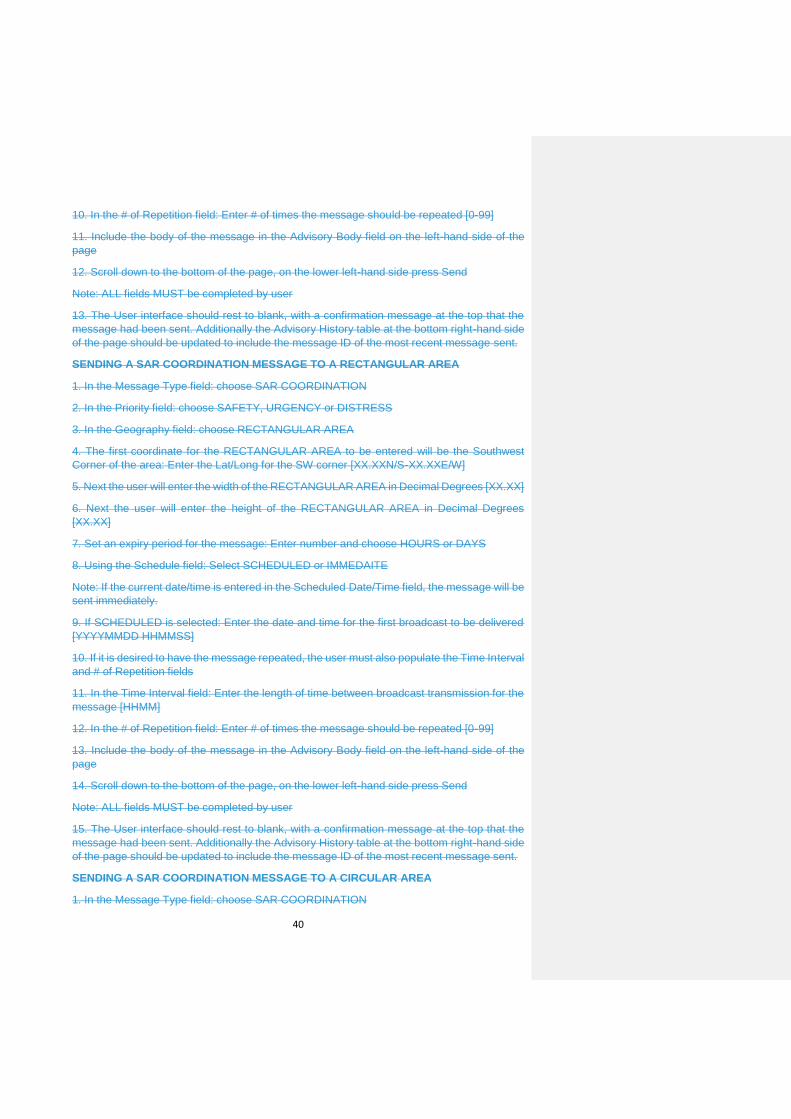
40
10. In the # of Repetition field: Enter # of times the message should be repeated [0-99]
11. Include the body of the message in the Advisory Body field on the left-hand side of the
page
12. Scroll down to the bottom of the page, on the lower left-hand side press Send
Note: ALL fields MUST be completed by user
13. The User interface should rest to blank, with a confirmation message at the top that the
message had been sent. Additionally the Advisory History table at the bottom right-hand side
of the page should be updated to include the message ID of the most recent message sent.
SENDING A SAR COORDINATION MESSAGE TO A RECTANGULAR AREA
1. In the Message Type field: choose SAR COORDINATION
2. In the Priority field: choose SAFETY, URGENCY or DISTRESS
3. In the Geography field: choose RECTANGULAR AREA
4. The first coordinate for the RECTANGULAR AREA to be entered will be the Southwest
Corner of the area: Enter the Lat/Long for the SW corner [XX.XXN/S-XX.XXE/W]
5. Next the user will enter the width of the RECTANGULAR AREA in Decimal Degrees [XX.XX]
6. Next the user will enter the height of the RECTANGULAR AREA in Decimal Degrees
[XX.XX]
7. Set an expiry period for the message: Enter number and choose HOURS or DAYS
8. Using the Schedule field: Select SCHEDULED or IMMEDAITE
Note: If the current date/time is entered in the Scheduled Date/Time field, the message will be
sent immediately.
9. If SCHEDULED is selected: Enter the date and time for the first broadcast to be delivered
[YYYYMMDD HHMMSS]
10. If it is desired to have the message repeated, the user must also populate the Time Interval
and # of Repetition fields
11. In the Time Interval field: Enter the length of time between broadcast transmission for the
message [HHMM]
12. In the # of Repetition field: Enter # of times the message should be repeated [0-99]
13. Include the body of the message in the Advisory Body field on the left-hand side of the
page
14. Scroll down to the bottom of the page, on the lower left-hand side press Send
Note: ALL fields MUST be completed by user
15. The User interface should rest to blank, with a confirmation message at the top that the
message had been sent. Additionally the Advisory History table at the bottom right-hand side
of the page should be updated to include the message ID of the most recent message sent.
SENDING A SAR COORDINATION MESSAGE TO A CIRCULAR AREA
1. In the Message Type field: choose SAR COORDINATION

41
2. In the Priority field: choose SAFETY, URGENCY or DISTRESS
3. In the Geography field: choose CIRCULAR AREA
4. The first coordinate for the CIRCULAR AREA to be entered will be the center of the
broadcast: Enter the Lat/Long for the center of the broadcast area [XX.XXN/S-XX.XXE/W]
5. Next the user will enter the radius of the CIRCULAR AREA in Kilometers [XXX]
6. Set an expiry period for the message: Enter number and choose HOURS or DAYS
7. Using the Schedule field: Select SCHEDULED or IMMEDAITE
Note: If the current date/time is entered in the Scheduled Date/Time field, the message will be
sent immediately.
8. If SCHEDULED is selected: Enter the date and time for the first broadcast to be delivered
[YYYYMMDD HHMMSS]
9. If it is desired to have the message repeated, the user must also populate the Time Interval
and # of Repetition fields
10. In the Time Interval field: Enter the length of time between broadcast transmission for the
message [HHMM]
11. In the # of Repetition field: Enter # of times the message should be repeated [0-99]
12. Include the body of the message in the Advisory Body field on the left-hand side of the
page
13. Scroll down to the bottom of the page, on the lower left-hand side press Send
Note: ALL fields MUST be completed by user
14. The User interface should rest to blank, with a confirmation message at the top that the
message had been sent. Additionally the Advisory History table at the bottom right-hand side
of the page should be updated to include the message ID of the most recent message sent.
SENDING A SAR COORDINATION MESSAGE TO A COASTAL AREA
1. In the Message Type field: choose SAR COORDINATION
2. In the Priority field: choose SAFETY or URGENCY
3. In the Geography field: choose COASTAL AREA
4. From the COASTAL AREA drop down list, select the desired COASTAL AREA: select
COASTAL AREA
Note: The available COASTAL AREAS will be unique to each NAVAREA or MSI Provider.
5. Set an expiry period for the message: Enter number and choose HOURS or DAYS
6. Using the Schedule field: Select SCHEDULED or IMMEDAITE
Note: If the current date/time is entered in the Scheduled Date/Time field, the message will be
sent immediately.
7. If SCHEDULED is selected: Enter the date and time for the first broadcast to be delivered
[YYYYMMDD HHMMSS]

42
8. If it is desired to have the message repeated, the user must also populate the Time Interval
and # of Repetition fields
9. In the Time Interval field: Enter the length of time between broadcast transmission for the
message [HHMM]
10. In the # of Repetition field: Enter # of times the message should be repeated [0-99]
11. Include the body of the message in the Advisory Body field on the left-hand side of the
page
12. Scroll down to the bottom of the page, on the lower left-hand side press Send
Note: ALL fields MUST be completed by user
13. The User interface should rest to blank, with a confirmation message at the top that the
message had been sent. Additionally the Advisory History table at the bottom right-hand side
of the page should be updated to include the message ID of the most recent message sent.
SENDING A DISTRESS ALERT RELAY TO A CIRCULAR AREA
1. In the Message Type field: choose SAR COORDINATION
2. In the Priority field: choose DISTRESS
3. In the Geography field: choose CIRCULAR AREA
4. The first coordinate for the CIRCULAR AREA to be entered will be the center of the
broadcast: Enter the Lat/Long for the center of the broadcast area [XX.XXN/S-XX.XXE/W]
5. Next the user will enter the radius of the CIRCULAR AREA in Kilometers [XXX]
6. Set an expiry period for the message: Enter number and choose HOURS or DAYS
7. Using the Schedule field: Select SCHEDULED or IMMEDAITE
Note: If the current date/time is entered in the Scheduled Date/Time field, the message will be
sent immediately.
8. If SCHEDULED is selected: Enter the date and time for the first broadcast to be delivered
[YYYYMMDD HHMMSS]
9. If it is desired to have the message repeated, the user must also populate the Time Interval
and # of Repetition fields
10. In the Time Interval field: Enter the length of time between broadcast transmission for the
message [HHMM]
11. In the # of Repetition field: Enter # of times the message should be repeated [0-99]
12. Include the body of the message in the Advisory Body field on the left-hand side of the
page
13. Scroll down to the bottom of the page, on the lower left-hand side press Send
Note: ALL fields MUST be completed by user
14. The User interface should rest to blank, with a confirmation message at the top that the
message had been sent. Additionally the Advisory History table at the bottom right-hand side
of the page should be updated to include the message ID of the most recent message sent.

43
Operational guidance – Part 2
Operational guidance
1 This annex appendix contains operational guidance for the benefit of registered MSI
and SAR related information providers who are responsible for preparing messages for
broadcast.
Use of the codes given in this Annex Appendix is mandatory for all messages in the
system.
2 Types of messages and message formats are detailed in the sub-parts of this
annexappendix.
Part A – Navigational warning service
Part B – Meteorological service
Part C – Search and rescue (SAR) services and SAR coordination traffic
Part D – Piracy countermeasures broadcast messages
Allocation of priority and services codes for services
Service
Message priority Service code (type)
Navigational warning services
C1 = 1 (Safety) – normally C1 = 2 (Urgency) – exceptionally at discretion of MSI provider
C2 = 04 – Navigational warning to a rectangular area C2 = 13 – Coastal warning to a coastal warning area C2 = 24 – Navigational warning to a circular area C2 = 31 – NAVAREA warning to a NAVAREA
Meteorological services
C1 = 1 (Safety) – always for forecasts and warnings C1 = 2 (Urgency) – always for urgent tropical cyclone warnings only
C2 = 04 – Meteorological warning or forecast to a rectangular area C2 = 13 – Meteorological warning or forecast to a coastal warning area C2 = 24 – Meteorological warning or forecast to a circular area

44
C2 = 31 – METAREA warning or meteorological forecast to a METAREA
SAR services: 1) Shore-to-ship
distress alert
C1 = 3 (Distress) – always C2 = 14 – Shore-to-ship distress alert to a circular area
2) SAR coordination traffic
C1 = 1 (Safety) – determined by the phase of emergency C1 = 2 (Urgency) – determined by the phase of emergency C1 = 3 (Distress) – determined by the phase of emergency
C2 = 34 – SAR coordination to a rectangular area C2 = 44 – SAR coordination to a circular area
3) Shore-to-ship urgency and safety traffic
C1 = 1 (Safety) C1 = 2 (Urgency)
C2 = 31 – Urgency and safety traffic
4) General (all ships call within the Inmarsat ocean region)
C1 = 2 (Urgency) C1 = 3 (Distress)
C2 = 00
Piracy countermeasures broadcast messages
C1 = 1 (Safety) C1 = 2 (Urgency) – for piracy attack warnings
C2 = 04 – Piracy warning to a rectangular area C2 = 13 – Piracy warning to a coastal warning area C2 = 24 – Piracy warning to a circular area C2 = 31 – Piracy warning to a NAVAREA
3 The broadcast parameters are controlled by the use of five (or six) C codes which are
combined into a generalized message address header format as follows:
C0:C1:C2:C3:C4:C5
(Spaces, colons or other delimiters between these codes will be required, depending on the
communication protocol of the addressed LES.)
C0 – Ocean region
C1 – Message priority
C2 – Service code
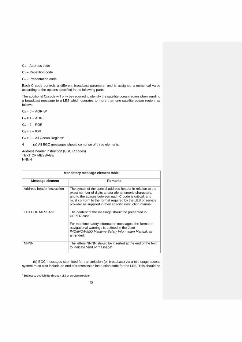
45
C3 – Address code
C4 – Repetition code
C5 – Presentation code
Each C code controls a different broadcast parameter and is assigned a numerical value
according to the options specified in the following parts.
The additional C0 code will only be required to identify the satellite ocean region when sending
a broadcast message to a LES which operates to more than one satellite ocean region, as
follows:
C0 = 0 – AOR-W
C0 = 1 – AOR-E
C0 = 2 – POR
C0 = 3 – IOR
C0 = 9 – All Ocean Regions4
4 (a) All EGC messages should comprise of three elements:
Address header instruction (EGC C codes)
TEXT OF MESSAGE
NNNN
Mandatory message element table
Message element
Remarks
Address header instruction
The syntax of the special address header in relation to the exact number of digits and/or alphanumeric characters, and to the spaces between each C code is critical, and must conform to the format required by the LES or service provider as supplied in their specific instruction manual.
TEXT OF MESSAGE
The content of the message should be presented in UPPER case. For maritime safety information messages, the format of navigational warnings is defined in the Joint IMO/IHO/WMO Maritime Safety Information Manual, as amended.
NNNN
The letters NNNN should be inserted at the end of the text to indicate "end of message".
(b) EGC messages submitted for transmission (or broadcast) via a two stage access
system must also include an end of transmission instruction code for the LES. This should be
4 Subject to availability through LES or service provider
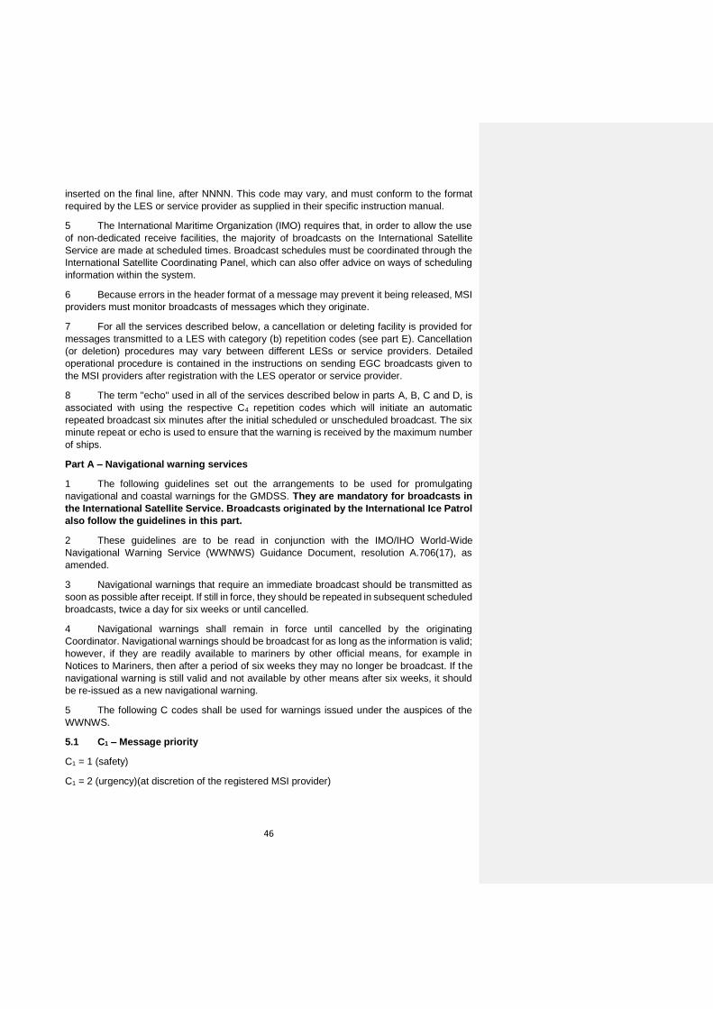
46
inserted on the final line, after NNNN. This code may vary, and must conform to the format
required by the LES or service provider as supplied in their specific instruction manual.
5 The International Maritime Organization (IMO) requires that, in order to allow the use
of non-dedicated receive facilities, the majority of broadcasts on the International Satellite
Service are made at scheduled times. Broadcast schedules must be coordinated through the
International Satellite Coordinating Panel, which can also offer advice on ways of scheduling
information within the system.
6 Because errors in the header format of a message may prevent it being released, MSI
providers must monitor broadcasts of messages which they originate.
7 For all the services described below, a cancellation or deleting facility is provided for
messages transmitted to a LES with category (b) repetition codes (see part E). Cancellation
(or deletion) procedures may vary between different LESs or service providers. Detailed
operational procedure is contained in the instructions on sending EGC broadcasts given to
the MSI providers after registration with the LES operator or service provider.
8 The term "echo" used in all of the services described below in parts A, B, C and D, is
associated with using the respective C4 repetition codes which will initiate an automatic
repeated broadcast six minutes after the initial scheduled or unscheduled broadcast. The six
minute repeat or echo is used to ensure that the warning is received by the maximum number
of ships.
Part A – Navigational warning services
1 The following guidelines set out the arrangements to be used for promulgating
navigational and coastal warnings for the GMDSS. They are mandatory for broadcasts in
the International Satellite Service. Broadcasts originated by the International Ice Patrol
also follow the guidelines in this part.
2 These guidelines are to be read in conjunction with the IMO/IHO World-Wide
Navigational Warning Service (WWNWS) Guidance Document, resolution A.706(17), as
amended.
3 Navigational warnings that require an immediate broadcast should be transmitted as
soon as possible after receipt. If still in force, they should be repeated in subsequent scheduled
broadcasts, twice a day for six weeks or until cancelled.
4 Navigational warnings shall remain in force until cancelled by the originating
Coordinator. Navigational warnings should be broadcast for as long as the information is valid;
however, if they are readily available to mariners by other official means, for example in
Notices to Mariners, then after a period of six weeks they may no longer be broadcast. If the
navigational warning is still valid and not available by other means after six weeks, it should
be re-issued as a new navigational warning.
5 The following C codes shall be used for warnings issued under the auspices of the
WWNWS.
5.1 C1 – Message priority
C1 = 1 (safety)
C1 = 2 (urgency)(at discretion of the registered MSI provider)

47
5.2 C2 – Service code5
C2 = 04 Navigational warning to a rectangular area*
C2 = 13 Coastal warning to a coastal warning area
C2 = 24 Navigational warning to a circular area
C2 = 31 NAVAREA warning to a NAVAREA
5.3 C3 – Address code
C3 = two digits X1X2
When C2 = 31, then: X1X2 are the two digits of the NAVAREA number (with a leading zero where necessary in the range 01 – 21).
C3 = four alphanumeric characters X1X2B1B2
When C2 = 13 for Coastal warnings, then: X1X2 are the two digits of the NAVAREA number (with a leading zero where necessary in the range 01 – 21) B1 is the coastal warning area A to Z B2 is the subject indicator and must always be A or L, where: A = Navigational warnings L = Other navigational warnings
C3 = twelve alphanumeric characters D1D2LaD3D4D5LoD6D7D8D9D10
When C2 = 04 for NAVAREA warnings within a rectangular area: D1D2 is latitude of south-west corner of the rectangle in degrees La is hemisphere which will always be N for Arctic NAVAREAs XVII to XXI D3D4D5 is longitude of south-west corner of rectangle in degrees, with leading zeros if required Lo is longitude E or W D6D7 is extent of rectangle in latitude (degrees) D8D9D10 is extent of rectangle in longitude (degrees)
Example: a rectangle whose south-west corner is 60°N and 010°W, extending 30° north and 25° east, is coded as: 60N010W30025
5 C2 = 04 may be used for NAVAREA warnings to a rectangular area by NAVAREAs XVII, XVIII, XIX, XX and XXI.

48
Note: Latitude and longitude are limited by values from 00° to 90° latitude and 000° to 180° longitude.
5.4 C4 – Repetition code
C4 = 01
May be used for initial unscheduled broadcast of NAVAREA warnings, and coastal warnings with no echo (transmit once on receipt)
C4 = 11 Recommended for use with initial unscheduled broadcast of NAVAREA warnings, and coastal warnings (transmit on receipt, echo six minutes later)
C4 = 16 Use for NAVAREA or coastal warnings scheduled for broadcast twice per day at 12 hour intervals with safety priority
Note: For NAVAREA or coastal warnings scheduled for broadcast more than twice per day, the appropriate C4 repetition code detailed in part E of this Manual must be used.
5.5 C5 – Presentation code
C5 = 00 The code 00 for International Alphabet Number 5 is normally used
Part B – Meteorological services
1 The following guidelines set out the arrangements to be used for promulgating
meteorological forecasts and warnings for the GMDSS. They are mandatory for broadcasts
in the International Satellite Service.
2 These guidelines are to be read in conjunction with the WMO Manual on Marine
Meteorological Services (WMO No. 558), as revised for the GMDSS.
3 In order to ensure uniformity of meteorological forecasts and warnings globally, the
following C codes should be used for meteorological services via Iridium.
3.1 C1 – Message priority
C1 = 2 (urgency) Only use for tropical cyclone warnings or urgent meteorological warnings with force 12 Beaufort or above
C1 = 1 (safety) For forecasts and other meteorological warnings
3.2 C2 – Service code6
C2 = 04 Meteorological warning or forecast to a rectangular area*
C2 = 04 may be used for METAREA warnings or meteorological forecasts to a rectangular area by
METAREAs XVII, XVIII, XIX, XX and XXI.

49
C2 = 13 Meteorological warning or forecast to a coastal warning area
C2 = 24 Meteorological warning or forecast to a circular area
C2 = 31 METAREA warning or meteorological forecast to a METAREA
3.3 C3 – Address code
C3 = ten alphanumeric characters D1D2LaD3D4D5LoR1R2R3
When C2 = 24 for meteorological warnings to user-defined circular area, then: D1D2La (three characters) is latitude of centre in degrees, and La whether north (N) or south (S). A leading zero should be used for latitudes less than 10° D3D4D5Lo (four characters) is longitude of centre in degrees, and Lo whether east (E) or west (W) of the prime meridian. One or two leading zeros should be used for longitudes less than 100° R1R2R3 (three characters) is radius of circle in nautical miles, up to 999. One or two leading zeros should be used for radius less than 100 nm
Example: A circle centred at latitude 56°N longitude 34°W with radius of 35 nautical miles is coded as: 56N034W035
C3 = two digits XX When C2 = 31, then: C3 = the two digits of the METAREA number (with a leading zero where necessary in the range 01 – 21)
C3 = four alphanumeric characters X1X2B1B2
When C2 = 13 for coastal warnings, then: X1X2 are the two digits of the METAREA number (with a leading zero where necessary in the range 01 – 21). B1 is the coastal warning area A to Z B2 is the subject indicator and must always be B or E, where: B = Meteorological warnings E = Meteorological forecasts
C3 = twelve alphanumeric characters D1D2LaD3D4D5LoD6D7D8D9D10
When C2 = 04 for meteorological warnings or forecasts within a rectangular area Note: The definition of 12 characters for a rectangular address is given in part A, paragraph 5.3

50
3.4 C4 – Repetition code
Category (a) repetition codes are used for meteorological services as follows:
C4 = 01 Use for meteorological forecast (transmit once on receipt)
C4 = 11 Use for meteorological warning (transmit on receipt followed by repeat six minutes later)
3.5 C5 – Presentation code
C5 = 00 The code 00 for International Alphabet Number 5 is normally used
Part C – Search and rescue services
1 The following guidelines set out the arrangements to be used by Rescue Coordination
Centres (RCCs) for initiating transmission of shore-to-ship distress alert relays and shore-to-
ship search and rescue information. Transmissions should be in accordance with the relevant
procedures of the International Telecommunication Union (ITU) Radio Regulations (RR), the
International Convention on Maritime Search and Rescue, 1979, as amended, and the
IAMSAR Manual.
2 In order to ensure uniformity of the search and rescue broadcast product throughout
the world, C codes should be used as described in this part.
3 Shore-to-ship distress alert relays
3.1 As a general principle, distress alert relays should be addressed to a circular area
around the estimated or known position of the distressed vessel. The radius of the circle
should be chosen to take account of the accuracy of the datum position, the expected density
of shipping in the vicinity and the fact that the position can only be defined in the message
address to the nearest whole degree of latitude and longitude. The distress alert relay
message must be broadcast via all satellites which cover the area concerned. Shore-to-ship
distress alert relays sent by the International Satellite Service should contain the identification
of the unit in distress, its approximate position and other information which might facilitate
rescue. Codes should be as follows:
3.2 C1 – Message priority
C1 = 3 (distress)
3.3 C2 – Service code
C2 = 14 (shore-to-ship distress alert to circular areas)
Messages addressed to circular areas will only be received and printed out by EGC receivers that are located inside the circle
3.4 C3 – Address code

51
C3 = ten alphanumeric characters D1D2LaD3D4D5LoR1R2R3
When C2 = 14 for distress alert to user-defined circular area, then: D1D2La (three characters) is latitude of vessel in distress in degrees (two digits) and whether north (N) or south (S): e.g. 39N (three characters total). A leading zero should be included for latitudes less than 10° D3D4D5Lo (four characters) is longitude of vessel in distress in degrees (three digits) and whether east (E) or west (W) of the prime meridian: e.g. 059W. A leading zero or zeros should be included for longitudes less than 100° or 10° as appropriate: e.g. use 099 for 99° and 008 for 8° R1R2R3 (three characters) is alert radius around distressed vessel in nautical miles. To ensure that position inaccuracies of both the distressed vessel and nearby vessels to which the message is intended do not affect receipt of messages, radius values of 200 nautical miles or larger should normally be used.
3.5 C4 – Repetition code
C4 = 11 Use for distress alerts (transmit on receipt followed by repeat six minutes later)
3.6 C5 – Presentation code
C5 = 00 The code 00 for International Alphabet Number 5 is normally used
4 General (all ships) call
4.1 When the RCC has no indication of the position of the vessel in distress, shore-to-ship
distress alert relays may be sent as general call. This will be printed in every vessel within the
ocean region.
Note: This method of alert should rarely be used.
The C0:C1:C2:C3:C4:C5 codes for general calls are always as follows:
C0 = 0 (1, 2 or 3) (if required)
C1 = 3 (distress) or 2 (urgency)
C2 = 00
C3 = 00
C4 = 11
C5 = 00
5 Search and rescue coordination traffic

52
5.1 Search and rescue coordination messages should be addressed to user-defined
circular or rectangular areas for the intent of coordinating the search and rescue of a vessel
in distress. Priority of the message will be determined by the phase of the emergency.
5.2 C1 – Message priority
C1 = 3 (distress), 2 (urgency) or 1 (safety)
5.3 C2 – Service code
C2 = 34
Search and rescue coordination to a rectangular area
C2 = 44
Search and rescue coordination to a circular area
5.4 C3 – Address code
C3 = twelve alphanumeric characters D1D2LaD3D4D5LoD6D7D8D9D10
When C2 = 34 Search and rescue coordination to a rectangular area Note: The definition of 12 characters for a rectangular address is given in part A, paragraph 5.3
C3 = ten alphanumeric characters D1D2LaD3D4D5LoR1R2R3
When C2 = 44 search and rescue coordination to a circular area Note: The definition of 10 characters for a circular address is given in part B, paragraph 3.3
5.5 C4 – Repetition code
C4 = 11 Use for distress alerts (transmit on receipt followed by repeat six minutes later)
5.6 C5 – Presentation code
C5 = 00 The code 00 for International Alphabet Number 5 is normally used
6 Shore-to-ship urgency and safety traffic
6.1 As a general principle, only the minimum information consistent with the safety of
navigation should be broadcast. However, where such information is deemed essential, shore-
to-ship information other than distress alerts should be broadcast to a NAVAREA using C
codes as follows:
6.2 C1 – Message priority
C1 = 2 (urgency) or 1 (safety)
6.3 C2 – Service code
C2 = 31
6.4 C3 – Address code
C3 = two digits X1X2 When C2 = 31, then:

53
X1X2 are the two digits of the NAVAREA number (with a leading zero where necessary in the range 01–21)
6.5 C4 – Repetition code
C4 = 11 Use for unscheduled broadcasts of urgency and safety traffic (transmit on receipt followed by repeat six minutes later)
6.6 C5 – Presentation code
C5 = 00 The code 00 for International Alphabet Number 5 is normally used
7 SAR broadcast for overlapping satellite ocean regions
7.1 Search and rescue distress and urgency broadcasts should be promulgated through
all satellites serving the area surrounding the vessel in distress. This is to ensure that vessels
will receive the message.
Part D – Piracy countermeasures broadcast messages
1 On receiving a message of alert or any other information concerning a threat of attack
(from the Security Forces Authority responsible for the operational application of the urgency
plans (countermeasures) in the region or another MRCC, for example), the MRCC should ask
the NAVAREA coordinator (or any other competent authority in accordance with local
arrangements), to send out a warning through the appropriate MSI network (NAVTEX or
satellite) and other broadcasting networks for warnings to shipping, if these exist.
2 There are two kinds of MSI messages associated with piracy countermeasures: the
daily situation report (SITREP) and a piracy attack warning. Specific guidance on drafting and
broadcasting these messages is given below.
3 The daily situation report should be broadcast at a regular time around 0800 local time
daily. The following paragraphs provide specific guidance on broadcast procedures.
4 The daily situation report should be broadcast to a rectangular area enclosing the
region of probable piracy attacks (based on historical data) plus a margin of 700 nautical miles
(24 hours steaming by a fast ship) in every direction.
5 The following C codes illustrate those to be used for broadcasts of the daily SITREP:
5.1 C1 – Message priority
C1 = 1 (safety)
5.2 C2 – Service code
C2 = 04 SITREP to a rectangular area
C2 = 24 SITREP to a circular area
5.3 C3 – Address code

54
C3 = twelve alphanumeric characters D1D2LaD3D4D5LoD6D7D8D9D10
When C2 = 04 SITREP to a rectangular area Note: The definition of 12 characters for a rectangular address is given in part A, paragraph 5.3
C3 = ten alphanumeric characters D1D2LaD3D4D5LoR1R2R3
When C2 = 24 SITREP to a circular area Note: The definition of 10 characters for a circular address is given in part B, paragraph 3.3
5.4 C4 – Repetition code
C4 = 18 Broadcast every 24 hours (no echo) until cancelled
5.5 C5 – Presentation code
C5 = 00 The code 00 for International Alphabet Number 5 is normally used
6 A piracy attack warning shall be broadcast as an "URGENT" NAVAREA or coastal
warning immediately on receipt of the source information and at least at the next scheduled
broadcast or for as long as the information remains valid. Urgent warnings will be broadcast
over all satellites which cover the affected region. Subject indicator character B2 = L should
be used in coastal warning areas. The specific area in which the attack has taken place is to
be quoted in the first line of the text, using no more detail than is necessary to indicate the
probable location of further attacks, e.g. WESTERN PHILIP CHANNEL or VICINITY
HORSBURGH LIGHT. The description of the pirate vessel and its last observed movements
are to be kept as brief as possible and should give only those details which are of significance
in avoiding other attacks.
7 The following C codes illustrate those to be used for broadcast of piracy attack
warnings:
7.1 C1 – Message priority
C1 = 2 (urgency)
7.2 C2 – Service code
C2 = 13
Coastal warning
C2 = 31
NAVAREA warning
7.3 C3 – Address code
C3 = two digits X1X2 When C2 = 31 then: X1X2 are the two digits of the NAVAREA number (with a leading zero where necessary in the range 01 to 21)
C3 = four alphanumeric characters X1X2B1B2
When C2 = 13 for coastal warnings then:

55
X1X2 are the two digits of the NAVAREA number (with a leading zero where necessary in the range 01 to 21) B1 is the coastal warning area A to Z B2 is the subject indicator and must always be A or L, where: A = Navigational warnings L = Other navigational warnings
7.4 C4 – Repetition code
C4 = 16
Broadcast every 12hours with no echo until cancelled
7.5 C5 – Presentation code
C5 = 00 The code 00 for International Alphabet Number 5 is normally used
8 Date/time should always be quoted in the form:
DDHHMM UTC MoMoMo YY
as in the example: 251256 UTC JUN 17
Note: UTC (Coordinated Universal Time) is the same time-zone as GMT (Z).
9 Geographical positions should be quoted in the standard format:
D1D2M1M2LaD3D4D5M3M4Lo
where:
D1D2 = degrees latitude (with leading zero if required)
M1M2 = minutes latitude
La = hemisphere (N or S)
D3D4D5 = degrees longitude (with leading zeros if required)
M3M4 = minutes longitude
Lo = longitude (E or W)
as in the example: 5419N10327E
Notes:
1. Examples of format and drafting guidance for piracy warnings is contained in the Joint
IMO/IHO/WMO Manual on Maritime Safety Information (MSC.1/Circ.1310, as amended, and
IHO Publication No. S-53).
2. Decimals of minutes will seldom be necessary or appropriate for reports of this kind.
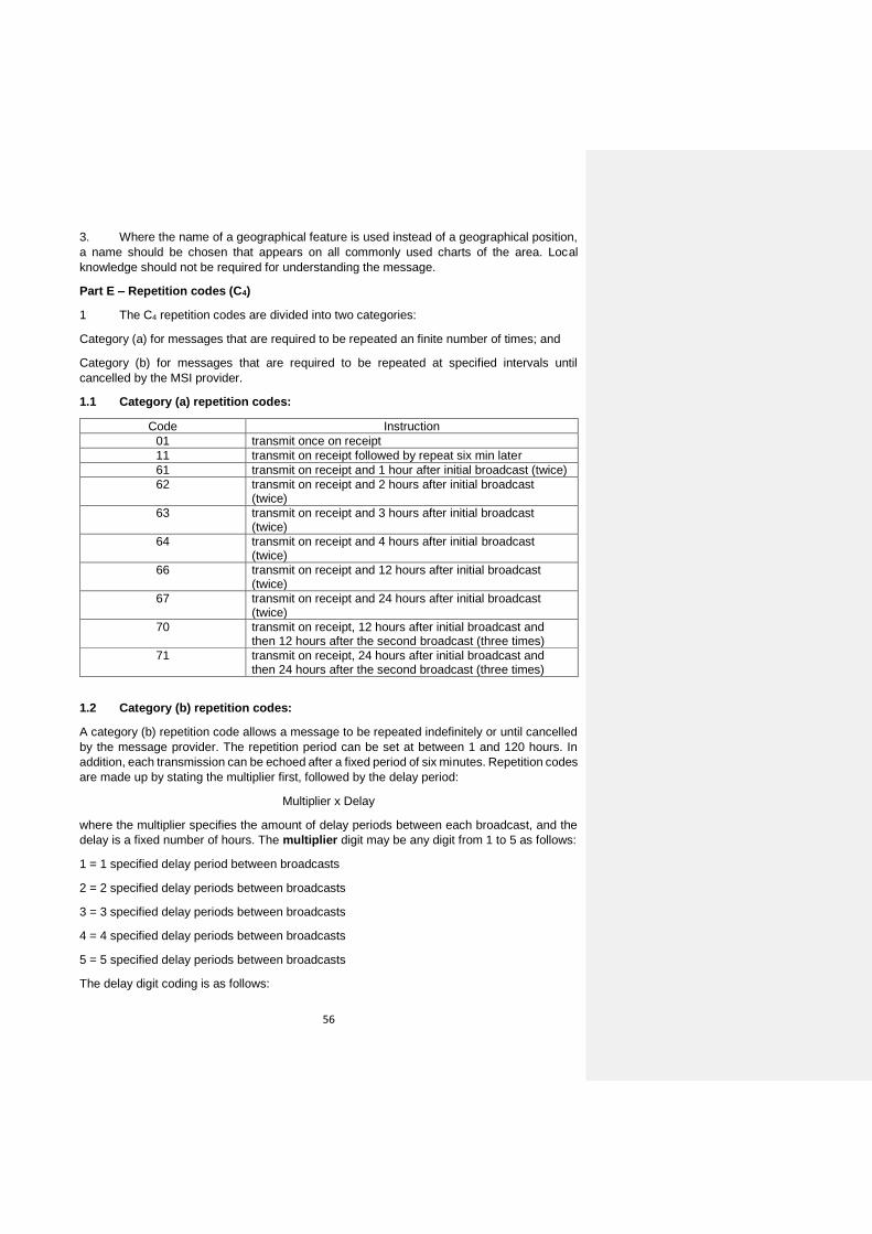
56
3. Where the name of a geographical feature is used instead of a geographical position,
a name should be chosen that appears on all commonly used charts of the area. Local
knowledge should not be required for understanding the message.
Part E – Repetition codes (C4)
1 The C4 repetition codes are divided into two categories:
Category (a) for messages that are required to be repeated an finite number of times; and
Category (b) for messages that are required to be repeated at specified intervals until
cancelled by the MSI provider.
1.1 Category (a) repetition codes:
Code Instruction
01 transmit once on receipt
11 transmit on receipt followed by repeat six min later
61 transmit on receipt and 1 hour after initial broadcast (twice)
62 transmit on receipt and 2 hours after initial broadcast (twice)
63 transmit on receipt and 3 hours after initial broadcast (twice)
64 transmit on receipt and 4 hours after initial broadcast (twice)
66 transmit on receipt and 12 hours after initial broadcast (twice)
67 transmit on receipt and 24 hours after initial broadcast (twice)
70 transmit on receipt, 12 hours after initial broadcast and then 12 hours after the second broadcast (three times)
71 transmit on receipt, 24 hours after initial broadcast and then 24 hours after the second broadcast (three times)
1.2 Category (b) repetition codes:
A category (b) repetition code allows a message to be repeated indefinitely or until cancelled
by the message provider. The repetition period can be set at between 1 and 120 hours. In
addition, each transmission can be echoed after a fixed period of six minutes. Repetition codes
are made up by stating the multiplier first, followed by the delay period:
Multiplier x Delay
where the multiplier specifies the amount of delay periods between each broadcast, and the
delay is a fixed number of hours. The multiplier digit may be any digit from 1 to 5 as follows:
1 = 1 specified delay period between broadcasts
2 = 2 specified delay periods between broadcasts
3 = 3 specified delay periods between broadcasts
4 = 4 specified delay periods between broadcasts
5 = 5 specified delay periods between broadcasts
The delay digit coding is as follows:
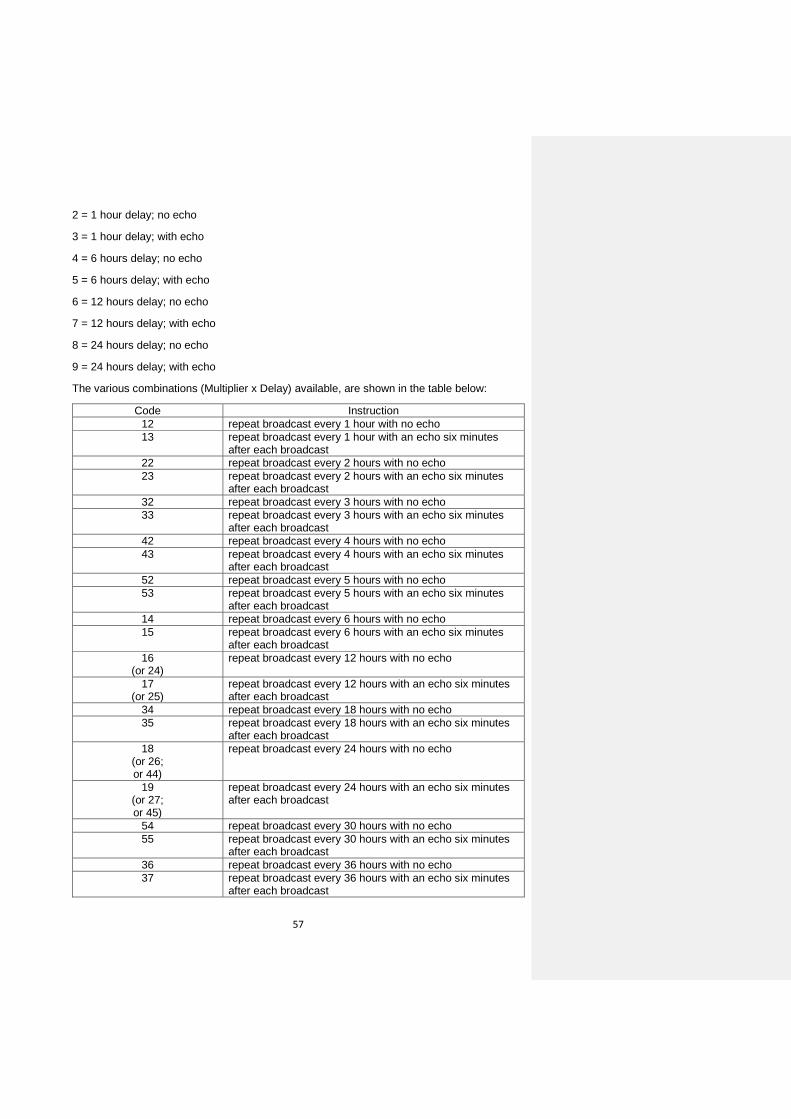
57
2 = 1 hour delay; no echo
3 = 1 hour delay; with echo
4 = 6 hours delay; no echo
5 = 6 hours delay; with echo
6 = 12 hours delay; no echo
7 = 12 hours delay; with echo
8 = 24 hours delay; no echo
9 = 24 hours delay; with echo
The various combinations (Multiplier x Delay) available, are shown in the table below:
Code Instruction
12 repeat broadcast every 1 hour with no echo
13 repeat broadcast every 1 hour with an echo six minutes after each broadcast
22 repeat broadcast every 2 hours with no echo
23 repeat broadcast every 2 hours with an echo six minutes after each broadcast
32 repeat broadcast every 3 hours with no echo
33 repeat broadcast every 3 hours with an echo six minutes after each broadcast
42 repeat broadcast every 4 hours with no echo
43 repeat broadcast every 4 hours with an echo six minutes after each broadcast
52 repeat broadcast every 5 hours with no echo
53 repeat broadcast every 5 hours with an echo six minutes after each broadcast
14 repeat broadcast every 6 hours with no echo
15 repeat broadcast every 6 hours with an echo six minutes after each broadcast
16 (or 24)
repeat broadcast every 12 hours with no echo
17 (or 25)
repeat broadcast every 12 hours with an echo six minutes after each broadcast
34 repeat broadcast every 18 hours with no echo
35 repeat broadcast every 18 hours with an echo six minutes after each broadcast
18 (or 26; or 44)
repeat broadcast every 24 hours with no echo
19 (or 27; or 45)
repeat broadcast every 24 hours with an echo six minutes after each broadcast
54 repeat broadcast every 30 hours with no echo
55 repeat broadcast every 30 hours with an echo six minutes after each broadcast
36 repeat broadcast every 36 hours with no echo
37 repeat broadcast every 36 hours with an echo six minutes after each broadcast

58
28 (or 46)
repeat broadcast every 48 hours with no echo
29 (or 47)
repeat broadcast every 48 hours with an echo six minutes after each broadcast
56 repeat broadcast every 60 hours with no echo
57 repeat broadcast every 60 hours with an echo six minutes after each broadcast
38 repeat broadcast every 72 hours with no echo
39 repeat broadcast every 72 hours with an echo six minutes after each broadcast
48 repeat broadcast every 96 hours with no echo
49 repeat broadcast every 96 hours with an echo six minutes after each broadcast
58 repeat broadcast every 120 hours with no echo
59 repeat broadcast every 120 hours with an echo six minutes after each broadcast
Note: Not all codes may be provided by all service providers.

59
Annex Appendix 5
PERFORMANCE STANDARDS FOR A SHIP EARTH STATION FOR USE IN THE GMDSS
RESOLUTION MSC.434(98) (Adopted on 16 June 2017)
PERFORMANCE STANDARDS FOR A SHIP EARTH STATION FOR USE IN THE GMDSS
THE MARITIME SAFETY COMMITTEE, RECALLING Article 28(b) of the Convention on the International Maritime Organization concerning the functions of the Committee, RECALLING ALSO resolution A.886(21), by which the Assembly resolved that the functions of adopting performance standards for radio and navigational equipment, as well as amendments thereto, should be performed by the Maritime Safety Committee on behalf of the Organization, RECALLING FURTHER regulations IV/10.1 and 14.1 of the International Convention for the Safety of Life at Sea (SOLAS), 1974, as amended, concerning radiocommunications for the Global Maritime Distress and Safety System (GMDSS), which require, respectively, that ships remaining in sea area A3 be provided with a ship earth station and that such ship earth stations shall conform to appropriate performance standards not inferior to those adopted by the Organization, FURTHER RECALLING resolution A.1001(25) by which the Assembly adopted the criteria and requirements for mobile-satellite communication services being designed for use in the GMDSS, NOTING that the International Mobile Satellite Organization (IMSO) oversees certain public interests in satellites' operations, including the continued provision of satellite services for the GMDSS, RECOGNIZING the need to prepare performance standards for satellite communication equipment designed in accordance with resolution A.1001(25) in order to ensure the operational reliability of such equipment and to avoid, as far as practicable, adverse interaction between satellite communication equipment and other communication and navigation equipment aboard the ship, HAVING CONSIDERED, at its [ninety-eighth] session, the recommendation made by the Sub-Committee on Navigation, Communications and Search and Rescue at its fourth session, 1 ADOPTS the Recommendation on performance standards for a ship earth station for use in the GMDSS, set out in the annex to the present resolution; 2 RECOMMENDS Governments to ensure that every ship earth station which forms part of the GMDSS:
.1 if designed to operate on a mobile satellite service recognized on or after 1 January 2021, comply with the relevant requirements of resolution A.1001(25) and
60
conform to performance standards not inferior to those specified in the annex to the present resolution; and
.2 if designed to operate on a mobile satellite service recognized before 1 January 2021:
.1 conforms to the relevant requirements of resolution A.1001(25) and to the performance standards not inferior to those specified in the annex to the present resolution; or
.2 conforms to performance standards not inferior to those specified in the annex to:
.1 resolution MSC.130(75) on Performance standards for Inmarsat ship earth stations capable of two-way communications, if installed after 1 February 1999;
.2 resolution A.808(19) on Performance Standards for Ship Earth Stations Capable of Two-Way Communications, if installed on or after 23 November 1996 and before 1 February 1999;
.3 resolution A.698(17) on Performance Standards for Ship Earth Stations Capable of Two-Way Communications, if installed before 23 November 1996
3 INVITES IMSO to coordinate with the recognized GMDSS service providers with a view to ensuring consistency between their ship earth station design and installation guidelines and the performance standards specified in the annex to the present resolution.

61
ANNEX
PERFORMANCE STANDARDS FOR A SHIP EARTH STATION FOR USE IN THE GMDSS
1 INTRODUCTION
1.1 The ship earth station installation capable of two-way radiocommunications should comply with the general requirements set out in resolutions A.694(17), A.813(19), MSC.191(79), and with the following minimum requirements.
2 TECHNICAL REQUIREMENTS
2.1 General
.1 The ship earth station should operate using a recognized mobile-satellite service and meet the functional requirements of resolution A.1001(25). The ship earth station should comply with the technical standard provided by the recognized mobile-satellite service provider and be certified by this provider for operation in the GMDSS, in order to ensure operational reliability.
.2 The ship earth station should comply with ITU Radio Regulations.
2.2 Functional requirements
.1 The ship earth station should be capable of automatically recognizing the priority of ship-to-ship, ship-to-shore and shore-to-ship communications and should process them in accordance with the message priority defined by the ITU Radio Regulations. The order of processing these communications should be:
.1 distress;
.2 urgency;
.3 safety; and
.4 other communications.
.2 The ship earth station should provide a specific visual indication when unable to detect or otherwise make contact with the satellites of the mobile-satellite system for a period of one minute or more, as referred to in the appendix.
2.3 Integrated systems and equipment interfaces
.1 The equipment should meet the requirements for Bridge Alert Management (BAM) system1. Equipment interfaces should comply with recognized international standards. Where the ship earth station is part of an Integrated Communication System (ICS), Integrated Navigation System (INS), Integrated Bridge System (IBS) or connected to a navigation system, this should not impair any of the GMDSS functions of these systems or the ship earth station itself.
1 Resolutions A.811(19), MSC.252(83) and MSC.302(87); guideline SN.1/Circ.288; international standards IEC 62940, IEC 61924-2 and IEC 62923.

62
.2 The ship earth station should provide an interface from which data from Enhanced Group Call (EGC) communications, including Maritime Safety Information (MSI), can be provided to navigation display systems, in accordance with recognized international standards.
.3 The ship earth station should provide either an integral electronic position
fixing equipment or have an interface for position updating conforming to the recognized international standards.
.4 The ship earth station should provide an interface in accordance with
recognized international standards to report a ship's identifier and location data from a received distress alert relay to navigation display systems in order to enable graphical display and possible linking to available target information.
3 OPERATION 3.1 Primary human-machine interface (HMI)
.1 The primary HMI should provide all functions necessary to carry out all communication procedures including those required by the GMDSS.
3.2 Ship earth station identity
.1 No control external to the equipment should be available for alteration of the ship station identity.
3.3 Transmission of distress alerts/calls
.1 It should be possible to initiate transmission of distress alerts/calls at any time. It should be possible to initiate transmission of distress alerts/calls whilst the ship earth station is transmitting lower priority communications, and whilst it is receiving communications of any priority, if necessary by pre-emption of those communications.
.2 It should be possible to initiate and make distress alerts/calls from the
position at which the ship is normally navigated. The equipment should include an option making it possible to initiate transmission of distress alerts/calls at a position remote from the primary HMI of the equipment.
.3 The HMI should include a dedicated distress button that has no other
function than activating distress transmissions. .4 A distress alert/call should be activated only by means of a dedicated
distress button (a physical button, not a touchscreen button). The dedicated distress button2 should not be any key of a digital input panel or a keyboard provided on the equipment. The distress button should be clearly identified and protected against inadvertent activation, requiring at least two independent actions. Lifting of the protective lid or cover is considered as the first action. Pressing the distress button as specified above is considered as the second independent action.
2 MSC/Circ.862.

63
.5 The distress button should be red in colour and marked "DISTRESS". Where a non-transparent protective lid or cover is used, it should be also be red in colour and marked "DISTRESS".
.6 The required protection of the distress button should consist of a
spring-loaded lid or cover permanently attached to the equipment by, e.g. hinges. It should not be necessary for the user to remove additional seals or to break the lid or cover in order to operate the distress button.
.7 The equipment should indicate the status of the distress alert/call.
The operation of the distress button should generate a visible and audible indication. The distress button should be kept pressed for at least 3 seconds. A flashing light and an intermittent audible signal should start immediately. After the transmission of the distress alert/call is initiated, the visual indication should become steady and the audible signal should cease.
.8 The equipment should automatically initiate repetitive initial distress
alerts/calls, which are repeated until cancelled on the ship or until appropriately acknowledged. It should be possible to interrupt repetitive initial distress alerts/calls. Such operation should not interrupt the transmission of a distress alert/call in progress but should prevent repetitive transmissions of a distress alert/call.
.9 The distress alert should contain identification of the station in distress, its
position and the time of the position fix. .10 The equipment should be capable of transmitting and receiving subsequent
distress communication. .11 After initiating a false distress alert/call, it should be possible to send a
cancellation of the alert/call. This cancellation should not be initiated by cutting the power supply to the ship earth station nor by the operator switching the ship earth station off.
3.4 Test facilities
.1 It should be possible to test the distress capability of the ship earth station without initiating a distress alert/call.
3.5 Reception of distress, urgency and safety alerts/calls
.1 It should be possible for the ship earth station to receive distress, urgency
and safety priority alerts/calls whilst it is being used for communications of a lower priority than that being received.
.2 Provision should be made for an audible signal and visual indication at the
position from which the ship is normally navigated, to indicate receipt of a distress or urgency enhanced group call message. It should not be possible to disable this indication and it should only be possible to reset it manually and only from the position where the message is displayed or printed. The audible signals for distress, urgency and their acknowledgements should be continuously repeated until manually terminated.

64
.3 For the presentation of received distress and urgency alerts/calls intended as text to be read, the equipment should include or interface to either: .1 an integrated printing device; or .2 a dedicated display device3, printer output port and a non-volatile
message memory; or .3 a connection to a navigation system and a non-volatile message
memory.
3.6 Audible signals and visual indications:
.1 The audible signals should be activated in relation to:
.1 distress alert/calls or distress relay alert/calls; and
.2 urgency calls and messages.
.2 For visual indication the ship earth station should conform to MSC 191(79). .3 BAM classification of priorities and categories is attached as appendix.
3.7 Enhanced Group Call (EGC) messages, including Maritime Safety Information (MSI)
.1 Facilities should be provided for the ship earth station to receive maritime safety information (MSI) for the NAVAREA/METAREA and the coastal warning areas and different classes of messages:
.1 where the ship is sailing and 300 NM beyond the limits of the
NAVAREA/METAREA; .2 for the planned voyage; and .3 for a fixed position. Additional means should be provided to filter received MSI based on NAVAREA/METAREA and the coastal warning area codes and different classes of messages.
.2 The station should be able to receive and filter distress relay and urgency
messages in accordance with area defined within the EGC message and the ship's position.
.3 For the presentation of received EGC communications intended as text to
be read, the equipment should include or interface to either:
.1 an integrated printing device; or
3 Where there is no printer, the display device should be located in the position from which the ship is normally navigated.

65
.2 a dedicated display device4, printer output port and a non-volatile message memory; or
.3 a connection to a navigation system and a non-volatile message
memory.
.4 If a dedicated display device or a connection to a navigation system is used, it should meet the general requirements of the Organization for such devices5 and the following additional requirements:
.1 the capability of showing at least 16 lines by 40 characters, with a
non-volatile memory of at least 255 messages of 1,023 characters; .2 an indication of newly received unsuppressed messages should be
immediately displayed until acknowledged, as referred to in the appendix; and
.3 the design and size of the display device should be such that
displayed information is easily read under all conditions, by observers at normal working distances and viewing angles.
.5 If a printing device is used, it should meet the general requirements of the
Organization for such devices and the following additional requirements:
.1 the printing device should be capable of printing at least the standard International Reference Alphabet (IRA) character set. Other character sets can be optionally used according to ISO 20226 standards and ITU-T Recommendations T.50;
.2 the printing device should be able to print at least 40 characters
per line; .3 means should be provided to prevent the re-printing of a message
once it has been received without error; .4 any messages should be displayed or printed regardless of the
character error rate of its reception. The equipment should use an asterisk (the "*" character) or a low line (the "_" character) if a corrupted character is received; and
.5 a "paper low" condition should generate a caution, as referred to in
the appendix.
.6 For the presentation of received group call messages intended as text to be read, or intended as imagery to be viewed, on another connected device or an integrated system, paragraph 2.3.1 also applies.
4 Where there is no printer, the dedicated display device should be located in the position from which the ship is normally navigated. 5 Resolution MSC.191(79). 6 ISO/IEC 2022:1994, Information technology – Character code structure and extension techniques.

66
3.8 Position updating
.1 Facilities should be provided to automatically update the ship's position and the time at which the position was determined from a suitable electronic position fixing equipment which may be an integral part of the equipment.
.2 To enable updating of the position:
.1 the status of the position update should be visible to the operator (e.g. offline, manual or automatic);
.2 if position data is being updated automatically, a caution should be
raised if no update has been performed for a period of 10 minutes, as referred to in the appendix. The caution should be removed by receiving new position data;
.3 the equipment should have facilities for manually entering the ship's
position and the time of the position fix; .4 if the ship's manually-set position is older than 4 hours, a caution
should be raised, as referred to in the appendix. The caution should be removed by inputting or receiving new position data; and
.5 if the ship’s position is older than 24 hours, the position is clearly
identified with date and time of the fix in UTC for distress alerting purposes.
4 POWER SUPPLY AND SOURCES OF ENERGY 4.1 The ship earth station should normally be powered from the ship's main source of
electrical energy. In addition, it should be possible to operate the ship earth station and all equipment necessary for its normal functioning, from an alternative source of electrical energy.
4.2 Changing from one source of supply to another or any interruption of up to 60 seconds
duration of the supply of electrical energy should not require the equipment to be manually re-initialized, should not result in loss of received communications stored in the memory and should not render the equipment inoperative when power is restored.
5 ANTENNA SITING 5.1 Where an omni-directional antenna is used, it is desirable that the antenna be sited
in such a position that no obstacle is likely to degrade significantly the performance of the equipment. The manufacturer should provide information, in the installation manual, on the required free line of sight and the angles in the fore and aft directions and in the port and starboard directions that are required for reliable operation, taking into account ship movements in heavy seas.
5.2 Where a stabilized directional antenna is used, it is desirable that the antenna be
sited in such a position that no obstacle is likely to degrade significantly the performance of the equipment. The manufacturer should provide information in the installation manual, on the required free line of sight and the angles of elevation required for reliable operation, taking into account ship movement in heavy seas.

67
5.3 For omni-directional antennas, the manufacturer should specify sizes and critical distances of objects related to the antenna which cause a shadow sector, likely to degrade significantly the performance of the equipment, taking into account ship movement in heavy seas. This information should be documented in the installation manual.
5.4 For directional antennas, the manufacturer should specify sizes and critical distances
of objects to the antenna, which cause shadow sectors, likely to degrade significantly the performance of the equipment, taking into account ship movement in heavy seas. This information should be documented in the installation manual.
5.5 To ensure reliable and continuous operation of the satellite communication system
the manufacturer should specify the necessary distances required between the satellite antenna and marine radar in the installation manual.
5.6 In case of multiple ship earth stations operating on adjacent frequency bands, the
antenna should be installed such as to ensure electromagnetic compatibility. 6 RADIO FREQUENCY RADIATION HAZARDS 6.1 A warning of potential radiation hazards should be displayed in appropriate locations.
A label should be attached external to a radome or antenna indicating the distances at which radiation levels of 100 W/m², 25 W/m² and 10 W/m² exist. These distances should be noted in the user manual.

68
APPENDIX
CLASSIFICATION OF SHIP EARTH STATION INDICATIONS BAM classification7 of ship earth station warnings or cautions, as specified in these performance standards.
Cause Alarm Warning Caution Category A Category B
No contact with satellites (referred to in paragraph 2.2.2)
X X
Received distress communications (referred to in paragraph 3.6)
X X
Received urgency message (referred to in paragraph 3.6)
X X
Received safety message (referred to in paragraph 3.7.4.2)
X X
Paper low (referred to in paragraph 3.7.5.5)
X X
Loss of position (referred to in paragraph 3.8.2.2)
X X
Manual position older than 4h (referred to in paragraph 3.8.2.4)
X X
***
7 As referred to in resolution MSC.302(87)

69
Annex Appendix 6
Procedure for amending the Interim Iridium Global Satellite EGC SafetyCast Service
Manual
1 Proposals for amendment or enhancement of the Interim Iridium Global Satellite EGC
SafetyCast Service Manual should be submitted to the IMO Maritime Safety Committee
through the Sub-Committee on Navigation, Communications and Search and Rescue
(NCSR).
2 Amendments to this Manual should normally be approved at intervals of approximately
two years or at such longer periods as determined by the Maritime Safety Committee at the
time of adoption. Amendments approved by the Maritime Safety Committee will be notified to
all concerned and will come into force on 1 January of the following year.
3 The agreement of the International Hydrographic Organization, the World
Meteorological Organization, the International Mobile Satellite Organization, and the active
participation of other bodies should be sought, according to the nature of the proposed
amendments.
***
Commented [A1]: IMO Secretariat to provide corrected text for this section.


![ANNEX DRAFT IRIDIUM GLOBAL SATELLITE EGC ......ANNEX DRAFT IRIDIUM GLOBAL SATELLITE EGC SYSTEM MANUAL [2019][2020] EDITION Foreword SOLAS regulation IV/12.2 states that "Every ship,](https://static.fdocuments.in/doc/165x107/5e67e4684c1eca5ff1385d15/annex-draft-iridium-global-satellite-egc-annex-draft-iridium-global-satellite.jpg)


![ANNEX DRAFT IRIDIUM GLOBAL SATELLITE EGC SYSTEM … Coordination... · 2019. 12. 4. · ANNEX DRAFT IRIDIUM GLOBAL SATELLITE EGC SYSTEM MANUAL [2019][2020] EDITION Foreword SOLAS](https://static.fdocuments.in/doc/165x107/60d0f9509ea1ec7d7b5c5d33/annex-draft-iridium-global-satellite-egc-system-coordination-2019-12-4.jpg)