ANNEX 6 RESOLUTION MSC.98(73) (adopted on 5 ... 73/21/Add.2 ANNEX 6 Page 4 I:\MSC\73\21a2.DOC...
42
MSC 73/21/Add.2 I:\MSC\73\21a2.DOC ANNEX 6 RESOLUTION MSC.98(73) (adopted on 5 December 2000) ADOPTION OF THE INTERNATIONAL CODE FOR FIRE SAFETY SYSTEMS THE MARITIME SAFETY COMMITTEE, RECALLING Article 28(b) of the Convention on the International Maritime Organization concerning the functions of the Committee, NOTING the revision of chapter II-2 of the International Convention for the Safety of Life at Sea (SOLAS), 1974 (hereinafter referred to as “the Convention ”), RECOGNIZING the need to continue the mandatory application of the fire safety systems required by the revised chapter II-2 of the Convention, NOTING resolution MSC.99(73) by which it adopted, inter alia, the revised chapter II-2 of the Convention to make the provisions of the International Code for Fire Safety Systems (FSS Code) mandatory under the Convention, HAVING CONSIDERED, at its seventy-third session, the text of the proposed FSS Code, 1. ADOPTS the International Code for Fire Safety Systems (FSS Code), the text of which is set out in the Annex to the present resolution; 2. INVITES Contracting Governments to the Convention to note that the FSS Code will take effect on 1 July 2002 upon the entry into force of the revised chapter II-2 of the Convention; 3. REQUESTS the Secretary-General to transmit certified copies of this resolution and the text of the FSS Code contained in the Annex to all Contracting Governments to the Convention; 4. FURTHER REQUESTS the Secretary-General to transmit copies of this resolution and the Annex to all Members of the Organization which are not Contracting Governments to the Convention.
Transcript of ANNEX 6 RESOLUTION MSC.98(73) (adopted on 5 ... 73/21/Add.2 ANNEX 6 Page 4 I:\MSC\73\21a2.DOC...
MSC 73/21/Add.2
I:\MSC\73\21a2.DOC
ANNEX 6
RESOLUTION MSC.98(73) (adopted on 5 December 2000)
ADOPTION OF THE INTERNATIONAL CODE FOR FIRE SAFETY SYSTEMS
THE MARITIME SAFETY COMMITTEE,
RECALLING Article 28(b) of the Convention on the International Maritime Organization concerning the functions of the Committee, NOTING the revision of chapter II-2 of the International Convention for the Safety of Life at Sea (SOLAS), 1974 (hereinafter referred to as “the Convention”),
RECOGNIZING the need to continue the mandatory application of the fire safety systems required by the revised chapter II-2 of the Convention,
NOTING resolution MSC.99(73) by which it adopted, inter alia, the revised chapter II-2 of the Convention to make the provisions of the International Code for Fire Safety Systems (FSS Code) mandatory under the Convention,
HAVING CONSIDERED, at its seventy-third session, the text of the proposed FSS Code, 1. ADOPTS the International Code for Fire Safety Systems (FSS Code), the text of which is set out in the Annex to the present resolution; 2. INVITES Contracting Governments to the Convention to note that the FSS Code will take effect on 1 July 2002 upon the entry into force of the revised chapter II-2 of the Convention; 3. REQUESTS the Secretary-General to transmit certified copies of this resolution and the text of the FSS Code contained in the Annex to all Contracting Governments to the Convention; 4. FURTHER REQUESTS the Secretary-General to transmit copies of this resolution and the Annex to all Members of the Organization which are not Contracting Governments to the Convention.
MSC 73/21/Add.2 ANNEX 6 Page 2
I:\MSC\73\21a2.DOC
ANNEX
INTERNATIONAL CODE FOR FIRE SAFETY SYSTEMS Table of contents Preamble Chapter 1 General Chapter 2 International shore connections Chapter 3 Personnel protection Chapter 4 Fire extinguishers Chapter 5 Fixed gas fire-extinguishing systems Chapter 6 Fixed foam fire-extinguishing systems Chapter 7 Fixed pressure water-spraying and water-mist fire-extinguishing systems Chapter 8 Automatic sprinkler, fire detection and fire alarm systems Chapter 9 Fixed fire detection and fire alarm systems Chapter 10 Sample extraction smoke detection systems Chapter 11 Low-location lighting systems Chapter 12 Fixed emergency fire pumps Chapter 13 Arrangement of means of escape Chapter 14 Fixed deck foam systems Chapter 15 Inert gas systems
MSC 73/21/Add.2 ANNEX 6
Page 3
I:\MSC\73\21a2.DOC
THE INTERNATIONAL CODE FOR FIRE SAFETY SYSTEMS
(Fire Safety Systems Code)
PREAMBLE 1 The purpose of this Code is to provide international standards of specific engineering specifications for fire safety systems required by chapter II-2 of the International Convention for the Safety of Life at Sea, 1974, as amended. 2 On or after 1 July 2002, this Code will be mandatory for fire safety systems required by the International Convention for the Safety of Life at Sea, 1974, as amended. Any future amendment to the Code must be adopted and brought into force in accordance with the procedure laid down in Article VIII of the Convention.
MSC 73/21/Add.2 ANNEX 6 Page 4
I:\MSC\73\21a2.DOC
CHAPTER 1 - GENERAL 1 Application
1.1 This code is applicable to fire safety systems as referred to in chapter II-2 of the International Convention for the Safety of Life at Sea, 1974, as amended. 1.2 Unless expressly provided otherwise, this Code is applicable for the fire safety systems of ships the keels of which are laid or which are at a similar stage of construction on or after 1 July 2002. 2 Definitions 2.1 Administration means the Government of the State whose flag the ship is entitled to fly. 2.2 Convention means the International Convention for the Safety of Life at Sea, 1974, as amended. 2.3 Fire Safety Systems Code means the International Code for Fire Safety Systems as defined in chapter II-2 of the International Convention for the Safety of Life at Sea, 1974, as amended. 2.4 For the purpose of this Code, definitions provided in chapter II-2 of the Convention also apply. 3 Use of equivalents and modern technology In order to allow modern technology and development of fire safety systems, the Administrations may approve fire safety systems which are not specified in this Code if the requirements of Part F of chapter II-2 of the Convention are fulfilled. 4 Use of toxic extinguishing media The use of a fire-extinguishing medium which, in the opinion of the Administration, either by itself or under expected conditions of use gives off toxic gases, liquids and other substances in such quantities as to endanger persons shall not be permitted.
CHAPTER 2 - INTERNATIONAL SHORE CONNECTIONS 1 Application This chapter details the specifications for international shore connections as required by chapter II-2 of the Convention. 2 Engineering specifications 2.1 Standard dimensions Standard dimensions of flanges for the international shore connection shall be in accordance with the following table:
MSC 73/21/Add.2 ANNEX 6
Page 5
I:\MSC\73\21a2.DOC
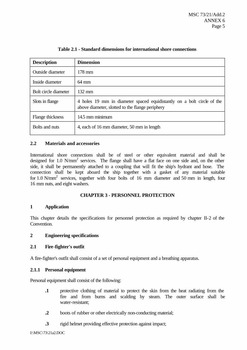
Table 2.1 - Standard dimensions for international shore connections
Description Dimension Outside diameter
178 mm
Inside diameter
64 mm
Bolt circle diameter
132 mm
Slots in flange
4 holes 19 mm in diameter spaced equidistantly on a bolt circle of the above diameter, slotted to the flange periphery
Flange thickness
14.5 mm minimum
Bolts and nuts
4, each of 16 mm diameter, 50 mm in length
2.2 Materials and accessories International shore connections shall be of steel or other equivalent material and shall be designed for 1.0 N/mm2 services. The flange shall have a flat face on one side and, on the other side, it shall be permanently attached to a coupling that will fit the ship's hydrant and hose. The connection shall be kept aboard the ship together with a gasket of any material suitable for 1.0 N/mm2 services, together with four bolts of 16 mm diameter and 50 mm in length, four 16 mm nuts, and eight washers.
CHAPTER 3 - PERSONNEL PROTECTION 1 Application This chapter details the specifications for personnel protection as required by chapter II-2 of the Convention. 2 Engineering specifications 2.1 Fire-fighter's outfit A fire-fighter's outfit shall consist of a set of personal equipment and a breathing apparatus. 2.1.1 Personal equipment Personal equipment shall consist of the following:
.1 protective clothing of material to protect the skin from the heat radiating from the fire and from burns and scalding by steam. The outer surface shall be water-resistant;
.2 boots of rubber or other electrically non-conducting material;
.3 rigid helmet providing effective protection against impact;
MSC 73/21/Add.2 ANNEX 6 Page 6
I:\MSC\73\21a2.DOC
.4 electric safety lamp (hand lantern) of an approved type with a minimum burning period of 3 h. Electric safety lamps on tankers and those intended to be used in hazardous areas shall be of an explosion-proof type; and
.5 axe with a handle provided with high-voltage insulation.
2.1.2 Breathing apparatus Breathing apparatus shall be a self-contained compressed air-operated breathing apparatus for which the volume of air contained in the cylinders shall be at least 1,200 l, or other self-contained breathing apparatus which shall be capable of functioning for at least 30 min. All air cylinders for breathing apparatus shall be interchangeable. 2.1.3 Lifeline For each breathing apparatus a fireproof lifeline of at least 30 m in length shall be provided. The lifeline shall successfully pass an approval test by statical load of 3.5 kN for 5 min without failure. The lifeline shall be capable of being attached by means of a snap-hook to the harness of the apparatus or to a separate belt in order to prevent the breathing apparatus becoming detached when the lifeline is operated. 2.2 Emergency escape breathing devices (EEBD) 2.2.1 General 2.2.1.1 An EEBD is a supplied air or oxygen device only used for escape from a compartment that has a hazardous atmosphere and shall be of an approved type. 2.2.1.2 EEBDs shall not be used for fighting fires, entering oxygen deficient voids or tanks, or worn by fire-fighters. In these events, a self-contained breathing apparatus, which is specifically suited for such applications, shall be used. 2.2.2 Definitions 2.2.2.1 Face piece means a face covering that is designed to form a complete seal around the eyes, nose and mouth which is secured in position by a suitable means. 2.2.2.2 Hood means a head covering which completely covers the head, neck, and may cover portions of the shoulders. 2.2.2.3 Hazardous atmosphere means any atmosphere that is immediately dangerous to life or health. 2.2.3 Particulars 2.2.3.1 The EEBD shall have a service duration of at least 10 min.
MSC 73/21/Add.2 ANNEX 6
Page 7
I:\MSC\73\21a2.DOC
2.2.3.2 The EEBD shall include a hood or full face piece, as appropriate, to protect the eyes, nose and mouth during escape. Hoods and face pieces shall be constructed of flame resistant materials and include a clear window for viewing. 2.2.3.3 An inactivated EEBD shall be capable of being carried hands-free. 2.2.3.4 An EEBD, when stored, shall be suitably protected from the environment. 2.2.3.5 Brief instructions or diagrams clearly illustrating their use shall be clearly printed on the EEBD. The donning procedures shall be quick and easy to allow for situations where there is little time to seek safety from a hazardous atmosphere. 2.2.4 Markings Maintenance requirements, manufacturer’s trademark and serial number, shelf life with accompanying manufacture date and name of approving authority shall be printed on each EEBD. All EEBD training units shall be clearly marked.
CHAPTER 4 - FIRE EXTINGUISHERS 1 Application This chapter details the specifications for fire extinguishers as required by chapter II-2 of the Convention. 1.2 Type approval All fire extinguishers shall be of approved types and designs based on the guidelines developed by the Organization.* 2 Engineering specifications 2.1 Fire extinguisher 2.1.1 Quantity of medium 2.1.1.1 Each powder or carbon dioxide extinguisher shall have a capacity of at least 5 kg and each foam extinguisher shall have a capacity of at least 9 l. The mass of all portable fire extinguishers shall not exceed 23 kg and they shall have a fire-extinguishing capability at least equivalent to that of a 9 l fluid extinguisher. 2.1.1.2 The Administration shall determine the equivalents of fire extinguishers. 2.1.2 Recharging Only refills approved for the fire extinguisher in question shall be used for recharging.
* Refer to the Guidelines for marine portable fire extinguishers adopted by the Organization by
resolution A.602(15).
MSC 73/21/Add.2 ANNEX 6 Page 8
I:\MSC\73\21a2.DOC
2.2 Portable foam applicators A portable foam applicator unit shall consist of a foam nozzle of an inductor type capable of being connected to the fire main by a fire hose, together with a portable tank containing at least 20 l of foam-making liquid and one spare tank of foam making liquid. The nozzle shall be capable of producing effective foam suitable for extinguishing an oil fire, at the rate of at least 1.5 m3/min.
CHAPTER 5 - FIXED GAS FIRE-EXTINGUISHING SYSTEMS 1 Application This chapter details the specifications for fixed gas fire-extinguishing systems as required by chapter II-2 of the Convention. 2 Engineering specifications 2.1 General 2.1.1 Fire-extinguishing medium 2.1.1.1 Where the quantity of the fire-extinguishing medium is required to protect more than one space, the quantity of medium available need not be more than the largest quantity required for any one space so protected. 2.1.1.2 The volume of starting air receivers, converted to free air volume, shall be added to the gross volume of the machinery space when calculating the necessary quantity of the fire-extinguishing medium. Alternatively, a discharge pipe from the safety valves may be fitted and led directly to the open air. 2.1.1.3 Means shall be provided for the crew to safely check the quantity of the fire-extinguishing medium in the containers. 2.1.1.4 Containers for the storage of fire-extinguishing medium and associated pressure components shall be designed to pressure codes of practice to the satisfaction of the Administration having regard to their locations and maximum ambient temperatures expected in service. 2.1.2 Installation requirements 2.1.2.1 The piping for the distribution of fire-extinguishing medium shall be arranged and discharge nozzles so positioned that a uniform distribution of the medium is obtained. 2.1.2.2 Except as otherwise permitted by the Administration, pressure containers required for the storage of fire-extinguishing medium, other than steam, shall be located outside the protected spaces in accordance with regulation II-2/10.4.3 of the Convention. 2.1.2.3 Spare parts for the system shall be stored on board and be to the satisfaction of the Administration.
MSC 73/21/Add.2 ANNEX 6
Page 9
I:\MSC\73\21a2.DOC
2.1.3 System control requirements 2.1.3.1 The necessary pipes for conveying fire-extinguishing medium into the protected spaces shall be provided with control valves so marked as to indicate clearly the spaces to which the pipes are led. Suitable provision shall be made to prevent inadvertent release of the medium into the space. Where a cargo space fitted with a gas fire-extinguishing system is used as a passenger space, the gas connection shall be blanked during such use. The pipes may pass through accommodations providing that they are of substantial thickness and that their tightness is verified with a pressure test, after their installation, at a pressure head not less than 5 N/mm2. In addition, pipes passing through accommodation areas shall be joined only by welding and shall not be fitted with drains or other openings within such spaces. The pipes shall not pass through refrigerated spaces. 2.1.3.2 Means shall be provided for automatically giving audible warning of the release of fire-extinguishing medium into any ro-ro spaces and other spaces in which personnel normally work or to which they have access. The pre-discharge alarm shall be automatically activated (e.g., by opening of the release cabinet door). The alarm shall operate for the length of time needed to evacuate the space, but in no case less than 20 s before the medium is released. Conventional cargo spaces and small spaces (such as compressor rooms, paint lockers, etc.) with only a local release need not be provided with such an alarm. 2.1.3.3 The means of control of any fixed gas fire-extinguishing system shall be readily accessible, simple to operate and shall be grouped together in as few locations as possible at positions not likely to be cut off by a fire in a protected space. At each location there shall be clear instructions relating to the operation of the system having regard to the safety of personnel. 2.1.3.4 Automatic release of fire-extinguishing medium shall not be permitted, except as permitted by the Administration. 2.2 Carbon dioxide systems 2.2.1 Quantity of fire extinguishing medium 2.2.1.1 For cargo spaces the quantity of carbon dioxide available shall, unless otherwise provided, be sufficient to give a minimum volume of free gas equal to 30% of the gross volume of the largest cargo space to be protected in the ship. 2.2.1.2 For machinery spaces the quantity of carbon dioxide carried shall be sufficient to give a minimum volume of free gas equal to the larger of the following volumes, either:
.1 40% of the gross volume of the largest machinery space so protected, the volume to exclude that part of the casing above the level at which the horizontal area of the casing is 40% or less of the horizontal area of the space concerned taken midway between the tank top and the lowest part of the casing; or
.2 35% of the gross volume of the largest machinery space protected, including the
casing.
MSC 73/21/Add.2 ANNEX 6 Page 10
I:\MSC\73\21a2.DOC
2.2.1.3 The percentages specified in paragraph 2.2.1.2 above may be reduced to 35% and 30%, respectively, for cargo ships of less than 2,000 gross tonnage where two or more machinery spaces, which are not entirely separate, are considered as forming one space. 2.2.1.4 For the purpose of this paragraph the volume of free carbon dioxide shall be calculated at 0.56 m3/kg. 2.2.1.5 For machinery spaces the fixed piping system shall be such that 85% of the gas can be discharged into the space within 2 min. 2.2.2 Controls Carbon dioxide systems shall comply with the following requirements:
.1 two separate controls shall be provided for releasing carbon dioxide into a protected space and to ensure the activation of the alarm. One control shall be used for opening the valve of the piping which conveys the gas into the protected space and a second control shall be used to discharge the gas from its storage containers; and
.2 the two controls shall be located inside a release box clearly identified for the
particular space. If the box containing the controls is to be locked, a key to the box shall be in a break-glass-type enclosure conspicuously located adjacent to the box.
2.3 Requirements of steam systems The boiler or boilers available for supplying steam shall have an evaporation of at least 1 kg of steam per hour for each 0.75 m3 of the gross volume of the largest space so protected. In addition to complying with the foregoing requirements the systems in all respects shall be as determined by, and to the satisfaction of, the Administration. 2.4 Systems using gaseous products of fuel combustion 2.4.1 General Where gas other than carbon dioxide or steam, as permitted by paragraph 2.3, is produced on the ship and is used as a fire-extinguishing medium, the system shall comply with the requirements in paragraph 2.4.2. 2.4.2 Requirements of the systems 2.4.2.1 Gaseous products Gas shall be a gaseous product of fuel combustion in which the oxygen content, the carbon monoxide content, the corrosive elements and any solid combustible elements in a gaseous product shall have been reduced to a permissible minimum.
MSC 73/21/Add.2 ANNEX 6
Page 11
I:\MSC\73\21a2.DOC
2.4.2.2 Capacity of fire-extinguishing systems 2.4.2.2.1 Where such gas is used as the fire-extinguishing medium in a fixed fire-extinguishing system for the protection of machinery spaces, it shall afford protection equivalent to that provided by a fixed system using carbon dioxide as the medium. 2.4.2.2.2 Where such gas is used as the fire-extinguishing medium in a fixed fire-extinguishing system for the protection of cargo spaces, a sufficient quantity of such gas shall be available to supply hourly a volume of free gas at least equal to 25 % of the gross volume of the largest space protected in this way for a period of 72 h. 2.5 Equivalent fixed gas fire-extinguishing systems for machinery spaces and cargo
pump rooms Fixed gas fire-extinguishing systems equivalent to those specified in paragraphs 2.2 to 2.4 shall be approved by the Administration based on the guidelines developed by the Organization.*
CHAPTER 6 - FIXED FOAM FIRE-EXTINGUISHING SYSTEMS 1 Application This chapter details the specifications for fixed foam fire-extinguishing systems as required by chapter II-2 of the Convention. 2 Engineering specifications 2.1 General Fixed foam fire-extinguishing systems shall be capable of generating foam suitable for extinguishing oil fires. 2.2 Fixed high-expansion foam fire-extinguishing systems 2.2.1 Quantity and performance of foam concentrates 2.2.1.1 The foam concentrates of high-expansion foam fire-extinguishing systems shall be approved by the Administration based on the guideline developed by the Organization.** 2.2.1.2 Any required fixed high-expansion foam system in machinery spaces shall be capable of rapidly discharging through fixed discharge outlets a quantity of foam sufficient to fill the greatest space to be protected at a rate of at least 1 m in depth per minute. The quantity of foam-forming liquid available shall be sufficient to produce a volume of foam equal to five times the volume of the largest space to be protected. The expansion ratio of the foam shall not exceed 1,000 to 1.
* Refer to the Revised guidelines for the approval of equivalent fixed gas fire-extinguishing systems, as
referred to in SOLAS 74, for machinery spaces and cargo pump rooms (MSC/Circ.848). ** Refer to the Guidelines for performance and testing criteria and surveys of high expansion foam
concentrates for fire-extinguishing systems (MSC/Circ.670).
MSC 73/21/Add.2 ANNEX 6 Page 12
I:\MSC\73\21a2.DOC
2.2.1.3 The Administration may permit alternative arrangements and discharge rates provided that it is satisfied that equivalent protection is achieved. 2.2.2 Installation requirements 2.2.2.1 Supply ducts for delivering foam, air intakes to the foam generator and the number of foam-producing units shall in the opinion of the Administration be such as will provide effective foam production and distribution. 2.2.2.2 The arrangement of the foam generator delivery ducting shall be such that a fire in the protected space will not affect the foam generating equipment. If the foam generators are located adjacent to the protected space, foam delivery ducts shall be installed to allow at least 450 mm of separation between the generators and the protected space. The foam delivery ducts shall be constructed of steel having a thickness of not less than 5 mm. In addition, stainless steel dampers (single or multi-bladed) with a thickness of not less than 3 mm shall be installed at the openings in the boundary bulkheads or decks between the foam generators and the protected space. The dampers shall be automatically operated (electrically, pneumatically or hydraulically) by means of remote control of the foam generator related to them. 2.2.2.3 The foam generator, its sources of power supply, foam-forming liquid and means of controlling the system shall be readily accessible and simple to operate and shall be grouped in as few locations as possible at positions not likely to be cut off by a fire in the protected space. 2.3 Fixed low-expansion foam fire-extinguishing systems 2.3.1 Quantity and foam concentrates 2.3.1.1 The foam concentrates of low-expansion foam fire-extinguishing systems shall be approved by the Administration based on the guidelines developed by the Organization.* 2.3.1.2 The system shall be capable of discharging through fixed discharge outlets in not more than 5 min a quantity of foam sufficient to cover to a depth of 150 mm the largest single area over which oil fuel is liable to spread. The expansion ratio of the foam shall not exceed 12 to 1. 2.3.2 Installation requirements 2.3.2.1 Means shall be provided for the effective distribution of the foam through a permanent system of piping and control valves or cocks to suitable discharge outlets, and for the foam to be effectively directed by fixed sprayers on other main fire hazards in the protected space. The means for effective distribution of the foam shall be proven acceptable to the Administration through calculation or by testing. 2.3.2.2 The means of control of any such systems shall be readily accessible and simple to operate and shall be grouped together in as few locations as possible at positions not likely to be cut off by a fire in the protected space.
* Refer to the Guidelines for performance and testing criteria and surveys of low expansion foam
concentrates for fire-extinguishing systems (MSC/Circ.582 and Corr.1).
MSC 73/21/Add.2 ANNEX 6
Page 13
I:\MSC\73\21a2.DOC
CHAPTER 7 - FIXED PRESSURE WATER-SPRAYING AND WATER-MIST FIRE-EXTINGUISHING SYSTEMS
1 Application This chapter details the specifications for fixed pressure water-spraying and water-mist fire-extinguishing systems as required by chapter II-2 of the Convention. 2 Engineering specifications 2.1 Fixed pressure water-spraying fire-extinguishing systems 2.1.1 Nozzles and pumps 2.1.1.1 Any required fixed pressure water-spraying fire-extinguishing system in machinery spaces shall be provided with spraying nozzles of an approved type. 2.1.1.2 The number and arrangement of the nozzles shall be to the satisfaction of the Administration and shall be such as to ensure an effective average distribution of water of at least 5 l/m2/min in the spaces to be protected. Where increased application rates are considered necessary, these shall be to the satisfaction of the Administration. 2.1.1.3 Precautions shall be taken to prevent the nozzles from becoming clogged by impurities in the water or corrosion of piping, nozzles, valves and pump. 2.1.1.4 The pump shall be capable of simultaneously supplying at the necessary pressure all sections of the system in any one compartment to be protected. 2.1.1.5 The pump may be driven by an independent internal combustion machinery, but, if it is dependent upon power being supplied from the emergency generator fitted in compliance with the provisions of regulation II-1/42 or regulation II-1/43 of the Convention, as appropriate, that generator shall be so arranged as to start automatically in case of main power failure so that power for the pump required by paragraph 2.1.1.4 is immediately available. The independent internal combustion machinery for driving the pump shall be so situated that a fire in the protected space or spaces will not affect the air supply to the machinery. 2.1.2 Installation requirements 2.1.2.1 Nozzles shall be fitted above bilges, tank tops and other areas over which oil fuel is liable to spread and also above other specific fire hazards in the machinery spaces. 2.1.2.2 The system may be divided into sections, the distribution valves of which shall be operated from easily accessible positions outside the spaces to be protected so as not to be readily cut off by a fire in the protected space.
MSC 73/21/Add.2 ANNEX 6 Page 14
I:\MSC\73\21a2.DOC
2.1.2.3 The pump and its controls shall be installed outside the space or spaces to be protected. It shall not be possible for a fire in the space or spaces protected by the water-spraying system to put the system out of action. 2.1.3 System control requirements The system shall be kept charged at the necessary pressure and the pump supplying the water for the system shall be put automatically into action by a pressure drop in the system. 2.2 Equivalent water-mist fire-extinguishing systems Water-mist fire-extinguishing systems for machinery spaces and cargo pump-rooms shall be approved by the Administration based on the guidelines developed by the Organization.*
CHAPTER 8 - AUTOMATIC SPRINKLER, FIRE DETECTION AND FIRE ALARM SYSTEMS
1 Application This chapter details the specifications for automatic sprinkler, fire detection and fire alarm systems as required by chapter II-2 of the SOLAS Convention. 2 Engineering specifications 2.1 General 2.1.1 Type of sprinkler systems The automatic sprinkler systems shall be of the wet pipe type, but small exposed sections may be of the dry pipe type where in the opinion of the Administration this is a necessary precaution. Saunas shall be fitted with a dry pipe system, with sprinkler heads having an operating temperature up to 140oC. 2.1.2 Sprinkler systems equivalent to those specified in paragraphs 2.2 to 2.4 Automatic sprinkler systems equivalent to those specified in paragraphs 2.2 to 2.4 shall be approved by the Administration based on the guidelines developed by the Organization.**
* Refer to the Alternative arrangements for halon fire-extinguishing systems in machinery spaces and
pump-rooms (MSC/Circ.668) and the Revised test method for equivalent water-based fire-extinguishing systems for machinery spaces of category A and cargo pump -rooms (MSC/Circ.728).
** Refer to the Revised Guidelines for approval of sprinkler systems equivalent to that referred to in SOLAS
regulation II-2/12 as adopted by the Organization by resolution A.800(19).
MSC 73/21/Add.2 ANNEX 6
Page 15
I:\MSC\73\21a2.DOC
2.2 Sources of power supply 2.2.1 Passenger ships There shall be not less than two sources of power supply for the sea water pump and automatic alarm and detection system. Where the sources of power for the pump are electrical, these shall be a main generator and an emergency source of power. One supply for the pump shall be taken from the main switchboard, and one from the emergency switchboard by separate feeders reserved solely for that purpose. The feeders shall be so arranged as to avoid galleys, machinery spaces and other enclosed spaces of high fire risk except in so far as it is necessary to reach the appropriate switchboards, and shall be run to an automatic changeover switch situated near the sprinkler pump. This switch shall permit the supply of power from the main switchboard so long as a supply is available therefrom, and be so designed that upon failure of that supply it will automatically change over to the supply from the emergency switchboard. The switches on the main switchboard and the emergency switchboard shall be clearly labelled and normally kept closed. No other switch shall be permitted in the feeders concerned. One of the sources of power supply for the alarm and detection system shall be an emergency source. Where one of the sources of power for the pump is an internal combustion engine it shall, in addition to complying with the provisions of paragraph 2.4.3, be so situated that a fire in any protected space will not affect the air supply to the machinery. 2.2.2 Cargo ships There shall not be less than two sources of power supply for the sea water pump and automatic alarm and detection system. If the pump is electrically driven it shall be connected to the main source of electrical power, which shall be capable of being supplied by at least two generators. The feeders shall be so arranged as to avoid galleys, machinery spaces and other enclosed spaces of high fire risk except in so far as it is necessary to reach the appropriate switchboards. One of the sources of power supply for the alarm and detection system shall be an emergency source. Where one of the sources of power for the pump is an internal combustion engine it shall, in addition to complying with the provisions of paragraph 2.4.3, be so situated that a fire in any protected space will not affect the air supply to the machinery. 2.3 Component requirements 2.3.1 Sprinklers 2.3.1.1 The sprinklers shall be resistant to corrosion by marine atmosphere. In accommodation and service spaces the sprinklers shall come into operation within the temperature range from 68oC to 79oC, except that in locations such as drying rooms, where high ambient temperatures might be expected, the operating temperature may be increased by not more than 30oC above the maximum deckhead temperature. 2.3.1.2 A quantity of spare sprinkler heads shall be provided for all types and ratings installed on the ship as follows: Total number of heads Required number of spares
<300 6 300 to 1000 12 >1000 24
MSC 73/21/Add.2 ANNEX 6 Page 16
I:\MSC\73\21a2.DOC
The number of spare sprinkler heads of any type need not exceed the total number of heads installed of that type. 2.3.2 Pressure tanks 2.3.2.1 A pressure tank having a volume equal to at least twice that of the charge of water specified in this paragraph shall be provided. The tank shall contain a standing charge of fresh water, equivalent to the amount of water which would be discharged in one minute by the pump referred to in paragraph 2.3.3.2, and the arrangements shall provide for maintaining an air pressure in the tank such as to ensure that where the standing charge of fresh water in the tank has been used the pressure will be not less than the working pressure of the sprinkler, plus the pressure exerted by a head of water measured from the bottom of the tank to the highest sprinkler in the system. Suitable means of replenishing the air under pressure and of replenishing the fresh water charge in the tank shall be provided. A glass gauge shall be provided to indicate the correct level of the water in the tank. 2.3.2.2 Means shall be provided to prevent the passage of sea water into the tank. 2.3.3 Sprinkler pumps 2.3.3.1 An independent power pump shall be provided solely for the purpose of continuing automatically the discharge of water from the sprinklers. The pump shall be brought into action automatically by the pressure drop in the system before the standing fresh water charge in the pressure tank is completely exhausted. 2.3.3.2 The pump and the piping system shall be capable of maintaining the necessary pressure at the level of the highest sprinkler to ensure a continuous output of water sufficient for the simultaneous coverage of a minimum area of 280 m2 at the application rate specified in paragraph 2.5.2.3. The hydraulic capability of the system shall be confirmed by the review of hydraulic calculations, followed by a test of the system, if deemed necessary by the Administration. 2.3.3.3 The pump shall have fitted on the delivery side a test valve with a short open-ended discharge pipe. The effective area through the valve and pipe shall be adequate to permit the release of the required pump output while maintaining the pressure in the system specified in paragraph 2.3.2.1. 2.4 Installation requirements 2.4.1 General Any parts of the system which may be subjected to freezing temperatures in service shall be suitably protected against freezing. 2.4.2 Piping arrangements 2.4.2.1 Sprinklers shall be grouped into separate sections, each of which shall contain not more than 200 sprinklers. In passenger ships any section of sprinklers shall not serve more than two decks and shall not be situated in more than one main vertical zone. However, the
MSC 73/21/Add.2 ANNEX 6
Page 17
I:\MSC\73\21a2.DOC
Administration may permit such a section of sprinklers to serve more than two decks or be situated in more than one main vertical zone, if it is satisfied that the protection of the ship against fire will not thereby be reduced. 2.4.2.2 Each section of sprinklers shall be capable of being isolated by one stop valve only. The stop valve in each section shall be readily accessible in a location outside of the associated section or in cabinets within stairway enclosures. The valve’s location shall be clearly and permanently indicated. Means shall be provided to prevent the operation of the stop valves by any unauthorized person. 2.4.2.3 A test valve shall be provided for testing the automatic alarm for each section of sprinklers by a discharge of water equivalent to the operation of one sprinkler. The test valve for each section shall be situated near the stop valve for that section. 2.4.2.4 The sprinkler system shall have a connection from the ship's fire main by way of a lockable screw-down non-return valve at the connection which will prevent a backflow from the sprinkler system to the fire main. 2.4.2.5 A gauge indicating the pressure in the system shall be provided at each section stop valve and at a central station. 2.4.2.6 The sea inlet to the pump shall wherever possible be in the space containing the pump and shall be so arranged that when the ship is afloat it will not be necessary to shut off the supply of sea water to the pump for any purpose other than the inspection or repair of the pump. 2.4.3 Location of systems The sprinkler pump and tank shall be situated in a position reasonably remote from any machinery space of category A and shall not be situated in any space required to be protected by the sprinkler system. 2.5 System control requirements 2.5.1 Ready availability 2.5.1.1 Any required automatic sprinkler, fire detection and fire alarm system shall be capable of immediate operation at all times and no action by the crew shall be necessary to set it in operation. 2.5.1.2 The automatic sprinkler system shall be kept charged at the necessary pressure and shall have provision for a continuous supply of water as required in this chapter. 2.5.2 Alarm and indication 2.5.2.1 Each section of sprinklers shall include means for giving a visual and audible alarm signal automatically at one or more indicating units whenever any sprinkler comes into operation. Such alarm systems shall be such as to indicate if any fault occurs in the system. Such units shall indicate in which section served by the system a fire has occurred and shall be centralised on the navigating bridge or in the continuously manned central control station and, in addition, visible
MSC 73/21/Add.2 ANNEX 6 Page 18
I:\MSC\73\21a2.DOC
and audible alarms from the unit shall also be placed in a position other than on the aforementioned spaces to ensure that the indication of fire is immediately received by the crew. 2.5.2.2 Switches shall be provided at one of the indicating positions referred to in paragraph 2.5.2.1 which will enable the alarm and the indicators for each section of sprinklers to be tested. 2.5.2.3 Sprinklers shall be placed in an overhead position and spaced in a suitable pattern to maintain an average application rate of not less than 5 l/m2/min over the nominal area covered by the sprinklers. However, the Administration may permit the use of sprinklers providing such an alternative amount of water suitably distributed as has been shown to the satisfaction of the Administration to be not less effective. 2.5.2.4 A list or plan shall be displayed at each indicating unit showing the spaces covered and the location of the zone in respect of each section. Suitable instructions for testing and maintenance shall be available. 2.5.3 Testing Means shall be provided for testing the automatic operation of the pump on reduction of pressure in the system.
CHAPTER 9 - FIXED FIRE DETECTION AND FIRE ALARM SYSTEMS
1 Application This chapter details the specifications for fixed fire detection and fire alarm systems as required by chapter II-2 of the Convention. 2 Engineering specifications 2.1 General requirements 2.1.1 Any required fixed fire detection and fire alarm system with manually operated call points shall be capable of immediate operation at all times. 2.1.2 The fixed fire detection and fire alarm system shall not be used for any other purpose, except that closing of fire doors and similar functions may be permitted at the control panel. 2.1.3 The system and equipment shall be suitably designed to withstand supply voltage variation and transients, ambient temperature changes, vibration, humidity, shock, impact and corrosion normally encountered in ships. 2.1.4 Zone address identification capability Fixed fire detection and fire alarm systems with a zone address identification capability shall be so arranged that:
MSC 73/21/Add.2 ANNEX 6
Page 19
I:\MSC\73\21a2.DOC
.1 means are provided to ensure that any fault (e.g. power break, short circuit, earth, etc.) occurring in the loop will not render the whole loop ineffective;
.2 all arrangements are made to enable the initial configuration of the system to be
restored in the event of failure (e.g. electrical, electronic, informatics, etc.);
.3 the first initiated fire alarm will not prevent any other detector from initiating further fire alarms; and
.4 no loop will pass through a space twice. When this is not practical (e.g. for large
public spaces), the part of the loop which by necessity passes through the space for a second time shall be installed at the maximum possible distance from the other parts of the loop.
2.2 Sources of power supply There shall be not less than two sources of power supply for the electrical equipment used in the operation of the fixed fire detection and fire alarm system, one of which shall be an emergency source. The supply shall be provided by separate feeders reserved solely for that purpose. Such feeders shall run to an automatic change-over switch situated in or adjacent to the control panel for the fire detection system. 2.3 Component requirements 2.3.1 Detectors 2.3.1.1 Detectors shall be operated by heat, smoke or other products of combustion, flame, or any combination of these factors. Detectors operated by other factors indicative of incipient fires may be considered by the Administration provided that they are no less sensitive than such detectors. Flame detectors shall only be used in addition to smoke or heat detectors. 2.3.1.2 Smoke detectors required in all stairways, corridors and escape routes within accommodation spaces shall be certified to operate before the smoke density exceeds 12.5% obscuration per metre, but not until the smoke density exceeds 2% obscuration per metre. Smoke detectors to be installed in other spaces shall operate within sensitivity limits to the satisfaction of the Administration having regard to the avoidance of detector insensitivity or oversensitivity. 2.3.1.3 Heat detectors shall be certified to operate before the temperature exceeds 78oC but not until the temperature exceeds 54oC, when the temperature is raised to those limits at a rate less than 1oC per minute. At higher rates of temperature rise, the heat detector shall operate within temperature limits to the satisfaction of the Administration having regard to the avoidance of detector insensitivity or oversensitivity. 2.3.1.4 The operation temperature of heat detectors in drying rooms and similar spaces of a normal high ambient temperature may be up to 130oC, and up to 140oC in saunas. 2.3.1.5 All detectors shall be of a type such that they can be tested for correct operation and restored to normal surveillance without the renewal of any component.
MSC 73/21/Add.2 ANNEX 6 Page 20
I:\MSC\73\21a2.DOC
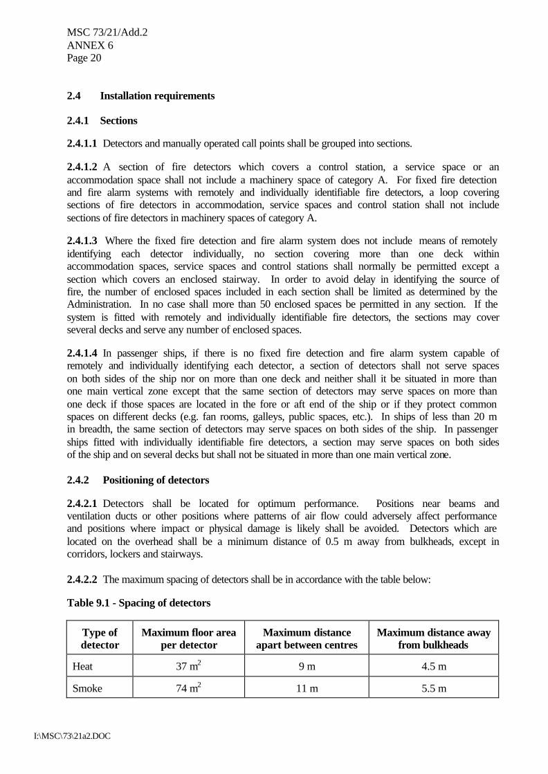
2.4 Installation requirements 2.4.1 Sections 2.4.1.1 Detectors and manually operated call points shall be grouped into sections. 2.4.1.2 A section of fire detectors which covers a control station, a service space or an accommodation space shall not include a machinery space of category A. For fixed fire detection and fire alarm systems with remotely and individually identifiable fire detectors, a loop covering sections of fire detectors in accommodation, service spaces and control station shall not include sections of fire detectors in machinery spaces of category A. 2.4.1.3 Where the fixed fire detection and fire alarm system does not include means of remotely identifying each detector individually, no section covering more than one deck within accommodation spaces, service spaces and control stations shall normally be permitted except a section which covers an enclosed stairway. In order to avoid delay in identifying the source of fire, the number of enclosed spaces included in each section shall be limited as determined by the Administration. In no case shall more than 50 enclosed spaces be permitted in any section. If the system is fitted with remotely and individually identifiable fire detectors, the sections may cover several decks and serve any number of enclosed spaces. 2.4.1.4 In passenger ships, if there is no fixed fire detection and fire alarm system capable of remotely and individually identifying each detector, a section of detectors shall not serve spaces on both sides of the ship nor on more than one deck and neither shall it be situated in more than one main vertical zone except that the same section of detectors may serve spaces on more than one deck if those spaces are located in the fore or aft end of the ship or if they protect common spaces on different decks (e.g. fan rooms, galleys, public spaces, etc.). In ships of less than 20 m in breadth, the same section of detectors may serve spaces on both sides of the ship. In passenger ships fitted with individually identifiable fire detectors, a section may serve spaces on both sides of the ship and on several decks but shall not be situated in more than one main vertical zone. 2.4.2 Positioning of detectors 2.4.2.1 Detectors shall be located for optimum performance. Positions near beams and ventilation ducts or other positions where patterns of air flow could adversely affect performance and positions where impact or physical damage is likely shall be avoided. Detectors which are located on the overhead shall be a minimum distance of 0.5 m away from bulkheads, except in corridors, lockers and stairways. 2.4.2.2 The maximum spacing of detectors shall be in accordance with the table below: Table 9.1 - Spacing of detectors
Type of detector
Maximum floor area
per detector
Maximum distance
apart between centres
Maximum distance away
from bulkheads Heat
37 m2
9 m
4.5 m
Smoke
74 m2
11 m
5.5 m
MSC 73/21/Add.2 ANNEX 6
Page 21
I:\MSC\73\21a2.DOC
The Administration may require or permit different spacing to that specified in the above table if based upon test data which demonstrate the characteristics of the detectors. 2.4.3 Arrangement of electric wiring 2.4.3.1 Electrical wiring which forms part of the system shall be so arranged as to avoid galleys, machinery spaces of category A, and other enclosed spaces of high fire risk except where it is necessary to provide for fire detection or fire alarm in such spaces or to connect to the appropriate power supply. 2.4.3.2 A loop of fire detection systems with a zone address identification capability shall not be damaged at more than one point by a fire. 2.5 System control requirements 2.5.1 Visual and audible fire signals* 2.5.1.1 The activation of any detector or manually operated call point shall initiate a visual and audible fire signal at the control panel and indicating units. If the signals have not received attention within 2 min an audible alarm shall be automatically sounded throughout the crew accommodation and service spaces, control stations and machinery spaces of category A. This alarm sounder system need not be an integral part of the detection system. 2.5.1.2 The control panel shall be located on the navigating bridge or in the continuously manned central control station. 2.5.1.3 Indicating units shall, as a minimum, denote the section in which a detector has been activated or manually operated call point has been operated. At least one unit shall be so located that it is easily accessible to responsible members of the crew at all times. One indicating unit shall be located on the navigating bridge if the control panel is located in the main fire control station. 2.5.1.4 Clear information shall be displayed on or adjacent to each indicating unit about the spaces covered and the location of the sections. 2.5.1.5 Power supplies and electric circuits necessary for the operation of the system shall be monitored for loss of power or fault conditions as appropriate. Occurrence of a fault condition shall initiate a visual and audible fault signal at the control panel which shall be distinct from a fire signal. 2.5.2 Testing Suitable instructions and component spares for testing and maintenance shall be provided.
* Refer to the Code on Alarms and Indicators as adopted by the Organization by resolution A.830(19).
MSC 73/21/Add.2 ANNEX 6 Page 22
I:\MSC\73\21a2.DOC
CHAPTER 10 - SAMPLE EXTRACTION SMOKE DETECTION SYSTEMS 1 Application This chapter details the specifications for sample extraction smoke detection systems as required by chapter II-2 of the Convention. 2 Engineering specifications 2.1 General requirements 2.1.1 Wherever in the text of this chapter the word "system" appears, it shall mean "sample extraction smoke detection system". 2.1.2 Any required system shall be capable of continuous operation at all times except that systems operating on a sequential scanning principle may be accepted, provided that the interval between scanning the same position twice gives an overall response time to the satisfaction of the Administration. 2.1.3 The system shall be designed, constructed and installed so as to prevent the leakage of any toxic or flammable substances or fire-extinguishing media into any accommodation and service space, control station or machinery space. 2.1.4 The system and equipment shall be suitably designed to withstand supply voltage variations and transients, ambient temperature changes, vibration, humidity, shock, impact and corrosion normally encountered in ships and to avoid the possibility of ignition of a flammable gas air mixture. 2.1.5 The system shall be of a type that can be tested for correct operation and restored to normal surveillance without the renewal of any component. 2.1.6 An alternative power supply for the electrical equipment used in the operation of the system shall be provided. 2.2 Component requirements 2.2.1 The sensing unit shall be certified to operate before the smoke density within the sensing chamber exceeds 6.65% obscuration per metre. 2.2.2 Duplicate sample extraction fans shall be provided. The fans shall be of sufficient capacity to operate under normal ventilation conditions in the protected area and shall give an overall response time to the satisfaction of the Administration. 2.2.3 The control panel shall permit observation of smoke in the individual sampling pipe. 2.2.4 Means shall be provided to monitor the airflow through the sampling pipes so designed as to ensure that as far as practicable equal quantities are extracted from each interconnected accumulator.
MSC 73/21/Add.2 ANNEX 6
Page 23
I:\MSC\73\21a2.DOC
2.2.5 Sampling pipes shall be a minimum of 12 mm internal diameter except when used in conjunction with fixed gas fire-extinguishing systems when the minimum size of pipe shall be sufficient to permit the fire-extinguishing gas to be discharged within the appropriate time. 2.2.6 Sampling pipes shall be provided with an arrangement for periodically purging with compressed air. 2.3 Installation requirements 2.3.1 Smoke accumulators 2.3.1.1 At least one smoke accumulator shall be located in every enclosed space for which smoke detection is required. However, where a space is designed to carry oil or refrigerated cargo alternatively with cargoes for which a smoke sampling system is required, means may be provided to isolate the smoke accumulators in such compartments for the system. Such means shall be to the satisfaction of the Administration. 2.3.1.2 Smoke accumulators shall be located for optimum performance and shall be spaced so that no part of the overhead deck area is more than 12 m measured horizontally from an accumulator. Where systems are used in spaces which may be mechanically ventilated, the position of the smoke accumulators shall be considered having regard to the effects of ventilation. 2.3.1.3 Smoke accumulators shall be positioned where impact or physical damage is unlikely to occur. 2.3.1.4 Not more than four accumulators shall be connected to each sampling point. 2.3.1.5 Smoke accumulators from more than one enclosed space shall not be connected to the same sampling point. 2.3.2 Sampling pipes 2.3.2.1 The sampling pipe arrangements shall be such that the location of the fire can be readily identified. 2.3.2.2 Sampling pipes shall be self-draining and suitably protected from impact or damage from cargo working. 2.4 System control requirements 2.4.1 Visual and audible fire signals 2.4.1.1 The control panel shall be located on the navigating bridge or in the continuously manned central control station. 2.4.1.2 Clear information shall be displayed on or adjacent to the control panel designating the spaces covered.
MSC 73/21/Add.2 ANNEX 6 Page 24
I:\MSC\73\21a2.DOC
2.4.1.3 The detection of smoke or other products of combustion shall initiate a visual and audible signal at the control panel and the navigating bridge or continuously manned central control station. 2.4.1.4 Power supplies necessary for the operation of the system shall be monitored for loss of power. Any loss of power shall initiate a visual and audible signal at the control panel and the navigating bridge which shall be distinct from a signal indicating smoke detection. 2.4.2 Testing Suitable instructions and component spares shall be provided for the testing and maintenance of the system.
CHAPTER 11 - LOW-LOCATION LIGHTING SYSTEMS 1 Application This chapter details the specifications for low-location lighting systems as required by chapter II-2 of the Convention.
2 Engineering specifications 2.1 General requirements Any required low-location lighting systems shall be approved by the Administration based on the guidelines developed by the Organization,* or to an international standard acceptable to the Organization.**
CHAPTER 12 - FIXED EMERGENCY FIRE PUMPS 1 Application This chapter details the specifications for emergency fire pumps as required by chapter II-2 of the Convention. This chapter is not applicable to passenger ships of l,000 gross tonnage and upwards. See regulation II-2/10.2.2.3.1.1 of the Convention for requirements for such ships. 2 Engineering specifications 2.1 General The emergency fire pump shall be of a fixed independently driven power-operated pump.
* Refer to the Guidelines for the evaluation, testing and application of low-location lighting on passenger
ships as adopted by the Organization by resolution A.752(18). ** Refer to the Recommendations by the International Organization for Standardization, in particular,
publication ISO 15370:2001 on Low-location lighting on passenger ships.
MSC 73/21/Add.2 ANNEX 6
Page 25
I:\MSC\73\21a2.DOC
2.2 Component requirements 2.2.1 Emergency fire pumps 2.2.1.1 Capacity of the pump The capacity of the pump shall not be less than 40% of the total capacity of the fire pumps required by regulation II-2/10.2.2.4.1 of the Convention and in any case not less than the follow: .1 for passenger ships less than 1,000 gross tonnage and for cargo 25 m3/h ships of 2,000 gross tonnage and upwards; and .2 for cargo ships less than 2,000 gross tonnage 15 m3/h. 2.2.1.2 Pressure at hydrants When the pump is delivering the quantity of water required by paragraph 2.2.1.1, the pressure at any hydrants shall be not less than the minimum pressure required by chapter II-2 of the Convention. 2.2.1.3 Suction heads The total suction head and the net positive suction head of the pump shall be determined having due regard to the requirements of the Convention and this chapter on the pump capacity and on the hydrant pressure under all conditions of list, trim, roll and pitch likely to be encountered in service. The ballast condition of a ship on entering or leaving a dry dock need not be considered a service condition. 2.2.2 Diesel engines and fuel tank 2.2.2.1 Starting of diesel engine Any diesel driven power source for the pump shall be capable of being readily started in its cold condition down to the temperature of 0oC by hand (manual) cranking. If this is impracticable, or if lower temperature are likely to be encountered, consideration is to be given to the provision and maintenance of heating arrangement, acceptable to the Administration so that ready starting will be assured. If hand (manual) starting is impracticable, the Administration may permit other means of starting. These means shall be such as to enable the diesel driven power source to be started at least six times within a period of 30 min and at least twice within the first 10 min. 2.2.2.2 Fuel tank capacity Any service fuel tank shall contain sufficient fuel to enable the pump to run on full load for at least three hours and sufficient reserves of fuel shall be available outside the machinery space of category A to enable the pump to be run on full load for an additional 15 h.
MSC 73/21/Add.2 ANNEX 6 Page 26
I:\MSC\73\21a2.DOC
CHAPTER 13 - ARRANGEMENT OF MEANS OF ESCAPE
1 Application This chapter details the specifications for means of escape as required by chapter II-2 of the Convention. 2 Passenger ships 2.1 Width of stairways 2.1.1 Basic requirements for stairway width Stairways shall not be less than 900 mm in clear width. The minimum clear width of stairways shall be increased by 10 mm for every one person provided for in excess of 90 persons. The total number of persons to be evacuated by such stairways shall be assumed to be two thirds of the crew and the total number of passengers in the areas served by such stairways. The width of the stairways shall not be inferior to those determined by paragraph 2.1.2. 2.1.2 Calculation method of stairway width 2.1.2.1 Basic principles of the calculation 2.1.2.1.1 This calculation method determines the minimum stairway width at each deck level, taking into account the consecutive stairways leading into the stairway under consideration. 2.1.2.1.2 It is the intention that the calculation method shall consider evacuation from enclosed spaces within each main vertical zone individually and take into account all of the persons using the stairway enclosures in each zone, even if they enter that stairway from another vertical zone. 2.1.2.1.3 For each main vertical zone the calculation shall be completed for the night time (case 1) and day time (case 2) and the largest dimension from either case used for determining the stairway width for each deck under consideration. 2.1.2.1.4 The calculation of stairway widths shall be based upon the crew and passenger load on each deck. Occupant loads shall be rated by the designer for passenger and crew accommodation spaces, service spaces, control spaces and machinery spaces. For the purpose of the calculation the maximum capacity of a public space shall be defined by either of the following two values: the number of seats or similar arrangements, or the number obtained by assigning 2 m2 of gross deck surface area to each person. 2.1.2.2 Calculation method for minimum value 2.1.2.2.1 Basic formulae In considering the design of stairway widths for each individual case which allow for the timely flow of persons evacuating to the muster stations from adjacent decks above and below, the following calculation methods shall be used (see figures 1 and 2):
MSC 73/21/Add.2 ANNEX 6
Page 27
I:\MSC\73\21a2.DOC
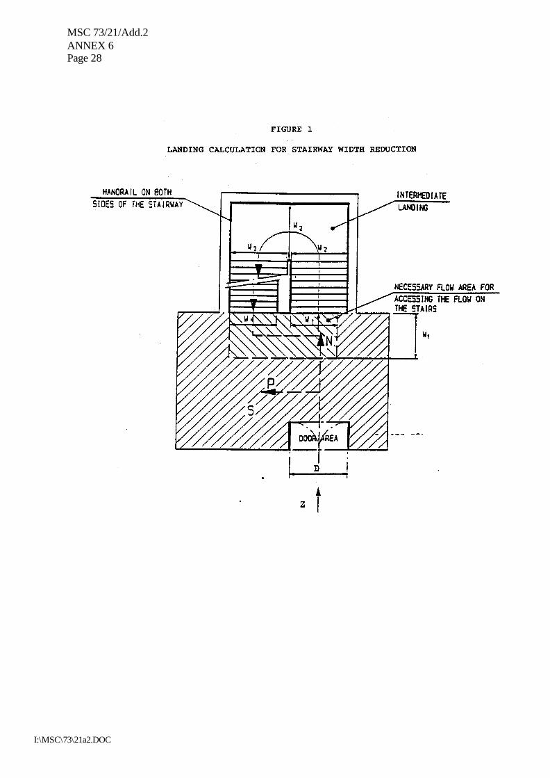
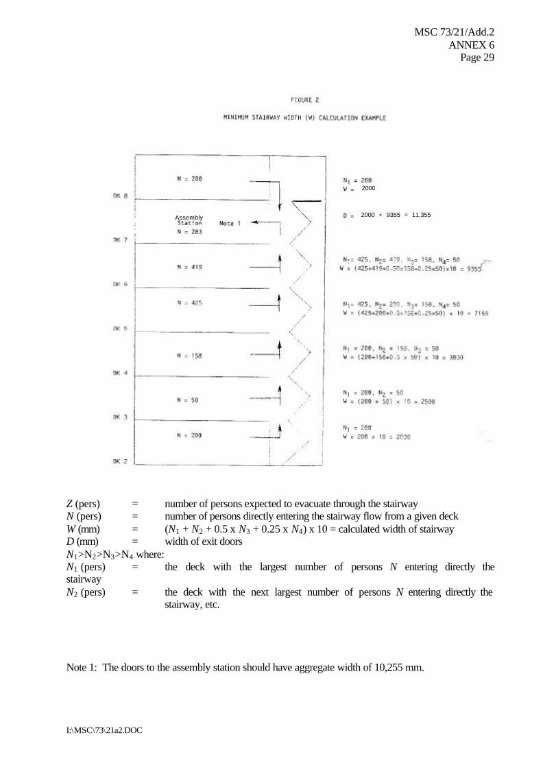
when joining two decks: W=(N1+N2) 10mm; when joining three decks: W=(N1+N2+0.5N3) 10mm; when joining four decks: W=(N1+N2+0.5N3+0.25N4) 10mm; when joining five decks or more decks, the width of the stairways shall be determined by applying the above formula for four decks to the deck under consideration and to the consecutive deck,
where: W = the required tread width between handrails of the stairway.
The calculated value of W may be reduced where available landing area S is provided in stairways at the deck level defined by subtracting P from Z, such that:
P = S 3.0 persons/m2 ; and Pmax = 0.25Z where:
Z = the total number of persons expected to be evacuated on the deck being considered; P = the number of persons taking temporary refuge on the stairway landing, which may be subtracted from Z to a maximum value of P = 0.25Z (to be rounded down to the nearest whole number) ; S = the surface area (m2) of the landing, minus the surface area necessary for the opening of doors and minus the surface area necessary for accessing the flow on stairs (see figure 1); N = the total number of persons expected to use the stairway from each consecutive deck under consideration; N1 is for the deck with the largest number of persons using that stairway; N2 is taken for the deck with the next highest number of persons directly entering the stairway flow such that, when sizing the stairway width as each deck level, N1 > N2 > N3 > N4 (see figure 2). These decks are assumed to be on or upstream (i.e. away from the embarkation deck) of the deck being considered.
MSC 73/21/Add.2 ANNEX 6 Page 28
I:\MSC\73\21a2.DOC
MSC 73/21/Add.2 ANNEX 6
Page 29
I:\MSC\73\21a2.DOC
Z (pers) = number of persons expected to evacuate through the stairway N (pers) = number of persons directly entering the stairway flow from a given deck W (mm) = (N1 + N2 + 0.5 x N3 + 0.25 x N4) x 10 = calculated width of stairway D (mm) = width of exit doors N1>N2>N3>N4 where: N1 (pers) = the deck with the largest number of persons N entering directly the stairway N2 (pers) = the deck with the next largest number of persons N entering directly the
stairway, etc. Note 1: The doors to the assembly station should have aggregate width of 10,255 mm.
2000 + 9355 = 11,355
2000
Assembly
MSC 73/21/Add.2 ANNEX 6 Page 30
I:\MSC\73\21a2.DOC
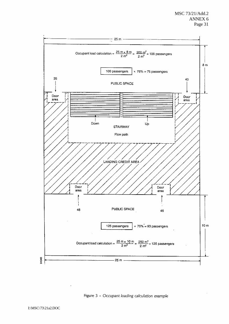
2.1.2.2.2 Distribution of persons 2.1.2.2.2.1 The dimension of the means of escape shall be calculated on the basis of the total number of persons expected to escape by the stairway and through doorways, corridors and landings (see figure 3). Calculations shall be made separately for the two cases of occupancy of the spaces specified below. For each component part of the escape route, the dimension taken shall not be less than the largest dimension determined for each case: Case 1: Passengers in cabins with maximum berthing capacity fully occupied; members
of the crew in cabins occupied to 2/3 of maximum berthing capacity; and service spaces occupied by 1/3 of the crew.
Case 2: Passengers in public spaces occupied to 3/4 of maximum capacity; members of
the crew in public spaces occupied to 1/3 of the maximum capacity; service spaces occupied by 1/3 of the crew; and crew accommodation occupied by 1/3 of the crew.
MSC 73/21/Add.2 ANNEX 6
Page 31
I:\MSC\73\21a2.DOC
MSC 73/21/Add.2 ANNEX 6 Page 32
I:\MSC\73\21a2.DOC
2.1.2.2.2.2 The maximum number of persons contained in a vertical zone, including persons entering stairways from another main vertical zone, shall not be assumed to be higher than the maximum number of persons authorized to be carried on board for the calculation of stairway width only. 2.1.3 Prohibition of decrease in width in the direction to the assembly station* The stairway shall not decrease in width in the direction of evacuation to the assembly station, except in the case of several assembly stations in one main vertical zone the stairway width shall not decrease in the direction of the evacuation to the most distant assembly station. 2.2 Details of stairways 2.2.1 Handrails Stairways shall be fitted with handrails on each side. The maximum clear width between handrails shall be 1,800 mm. 2.2.2 Alignment of stairways All stairways sized for more than 90 persons shall be aligned fore and aft. 2.2.3 Vertical rise and inclination Stairways shall not exceed 3.5 m in vertical rise without the provision of a landing and shall not have an angle of inclination greater than 45°. 2.2.4 Landings Landings at each deck level shall be not less than 2 m2 in area and shall increase by 1 m2 for every 10 persons provided for in excess of 20 persons but need not exceed 16 m2, except for those landings servicing public spaces having direct access onto the stairway enclosure. 2.3 Doorways and corridors 2.3.1 Doorways and corridors and intermediate landings included in means of escape shall be sized in the same manner as stairways. 2.3.2 The aggregate width of stairway exit doors to the assembly station shall not be less than the aggregate width of stairways serving this deck. 2.4 Evacuation routes to the embarkation deck 2.4.1 Assembly station It shall be recognized that the evacuation routes to the embarkation deck may include an assembly station. In this case consideration shall be given to the fire-protection requirements and sizing of corridors and doors from the stairway enclosure to the assembly station and from the
* Refer to the Indication of the “assembly stations” in passenger ships (MSC/Circ.777).
MSC 73/21/Add.2 ANNEX 6
Page 33
I:\MSC\73\21a2.DOC
assembly station to the embarkation deck, noting that evacuation of persons from assembly stations to embarkation positions will be carried out in small control groups. 2.4.2 Routes from the assembly station to the survival craft embarkation position Where the passengers and crew are held at an assembly station which is not at the survival craft embarkation position, the dimension of stairway width and doors from the assembly station to this position shall not be based on the number of persons in the controlled group. The width of these stairways and doors need not exceed 1,500 mm unless larger dimensions are required for evacuation of these spaces under normal conditions. 2.5 Means of escape plans 2.5.1 Means of escape plans shall be provided indicating the following:
.1 the number of the crew and passengers in all normally occupied spaces; .2 the number of crew and passengers expected to escape by stairway and through
doorways, corridors and landings;
.3 assembly stations and survival craft embarkation positions;
.4 primary and secondary means of escape; and
.5 width of stairways, doors, corridors and landing areas. 2.5.2 Means of escape plans shall be accompanied by detailed calculation for determining the width of escape stairways, doors, corridors and landing areas. 3 Cargo ships Stairways and corridors used as means of escape shall be not less than 700 mm in clear width and shall have a handrail on one side. Stairways and corridors with a clear width of 1,800 mm and over shall have handrails on both sides. “Clear width” is considered the distance between the handrail and the bulkhead on the other side or between the handrails. The angle of inclination of stairways should be, in general, 45º, but not greater than 50º, and in machinery spaces and small spaces not more than 60º. Doorways which give access to a stairway shall be of the same size as the stairway.
CHAPTER 14 - FIXED DECK FOAM SYSTEMS 1 Application This chapter details the specifications for fixed deck foam systems which are required to be provided by chapter II-2 of the Convention.
MSC 73/21/Add.2 ANNEX 6 Page 34
I:\MSC\73\21a2.DOC
2 Engineering specifications 2.1 General 2.1.1 The arrangements for providing foam shall be capable of delivering foam to the entire cargo tanks deck area as well as into any cargo tank the deck of which has been ruptured. 2.1.2 The deck foam system shall be capable of simple and rapid operation. 2.1.3 Operation of a deck foam system at its required output shall permit the simultaneous use of the minimum required number of jets of water at the required pressure from the fire main. 2.2 Component requirements 2.2.1 Foam solution and foam concentrate 2.2.1.1 The rate of supply of foam solution shall be not less than the greatest of the following: .1 0.6 l/min per square metre of cargo tanks deck area, where cargo tanks deck area
means the maximum breadth of the ship multiplied by the total longitudinal extent of the cargo tank spaces;
.2 6 l/min per square metre of the horizontal sectional area of the single tank having
the largest such area; or .3 3 l/min per square metre of the area protected by the largest monitor, such area
being entirely forward of the monitor, but not less than 1,250 l/min. 2.2.1.2 Sufficient foam concentrate shall be supplied to ensure at least 20 min of foam generation in tankers fitted with an inert gas installation or 30 min of foam generation in tankers not fitted with an inert gas installation when using solution rates stipulated in paragraph 2.2.1, as appropriate, whichever is the greatest. The foam expansion ratio (i.e., the ratio of the volume of foam produced to the volume of the mixture of water and foam-making concentrate supplied) shall not generally exceed 12 to 1. Where systems essentially produce low expansion foam, but an expansion ratio slightly in excess of 12 to 1, the quantity of foam solution available shall be calculated as for 12 to 1 expansion ratio systems.* When medium expansion ratio foam** (between 50 to 1 and 150 to 1 expansion ratio) is employed, the application rate of the foam and the capacity of a monitor installation shall be to the satisfaction of the Administration.
* Refer to the Guidelines for the performance and testing criteria, and surveys of low-expansion foam
concentrates for fixed fire-extinguishing systems (MSC/Circ.582 and Corr.1). ** Refer to the Guidelines for the performance and testing criteria, and surveys of medium expansion foam
concentrates for fixed fire-extinguishing systems (MSC/Circ.798).
MSC 73/21/Add.2 ANNEX 6
Page 35
I:\MSC\73\21a2.DOC
2.2.2 Monitors and foam applicators 2.2.2.1 Foam from the fixed foam system shall be supplied by means of monitors and foam applicators. At least 50% of the foam solution supply rate required in paragraphs 2.2.1.1.1 and 2.2.1.1.2 shall be delivered from each monitor. On tankers of less than 4,000 tonnes deadweight the Administration may not require installation of monitors but only applicators. However, in such a case the capacity of each applicator shall be at least 25% of the foam solution supply rate required in paragraphs 2.2.1.1.1 or 2.2.1.1.2. 2.2.2.2 The capacity of any monitor shall be at least 3 l/min of foam solution per square metre of deck area protected by that monitor, such area being entirely forward of the monitor. Such capacity shall be not less than 1,250 l/min. 2.2.2.3 The capacity of any applicator shall be not less than 400 l/min and the applicator throw in still air conditions shall be not less than 15 m. 2.3 Installation requirements 2.3.1 Main control station The main control station for the system shall be suitably located outside the cargo area, adjacent to the accommodation spaces and readily accessible and operable in the event of fire in the areas protected. 2.3.2 Monitors 2.3.2.1 The number and position of monitors shall be such as to comply with paragraph 2.1.1. 2.3.2.2 The distance from the monitor to the farthest extremity of the protected area forward of that monitor shall not be more than 75% of the monitor throw in still air conditions. 2.3.2.3 A monitor and hose connection for a foam applicator shall be situated both port and starboard at the front of the poop or accommodation spaces facing the cargo tanks deck. On tankers of less than 4,000 tonnes deadweight a hose connection for a foam applicator shall be situated both port and starboard at the front of the poop or accommodation spaces facing the cargo tanks deck. 2.3.3 Applicators 2.3.3.1 The number of foam applicators provided shall be not less than four. The number and disposition of foam main outlets shall be such that foam from at least two applicators can be directed on to any part of the cargo tanks deck area. 2.3.3.2 Applicators shall be provided to ensure flexibility of action during fire-fighting operations and to cover areas screened from the monitors. 2.3.4 Isolation valves Valves shall be provided in the foam main, and in the fire main when this is an integral part of the deck foam system, immediately forward of any monitor position to isolate damaged sections of those mains.
MSC 73/21/Add.2 ANNEX 6 Page 36
I:\MSC\73\21a2.DOC
CHAPTER 15 - INERT GAS SYSTEMS
1 Application This chapter details the specifications for inert gas systems as required by chapter II-2 of the Convention. 2 Engineering specifications 2.1 General 2.1.1 Throughout this chapter the term cargo tank includes also slop tanks. 2.1.2 The inert gas system referred to in chapter II-2 of the Convention shall be designed, constructed and tested to the satisfaction of the Administration. It shall be so designed* and operated as to render and maintain the atmosphere of the cargo tanks non-flammable at all times, except when such tanks are required to be gas-free. In the event that the inert gas system is unable to meet the operational requirement set out above and it has been assessed that it is impracticable to effect a repair, then cargo discharge, deballasting and necessary tank cleaning shall only be resumed when the "emergency conditions" specified in the Guidelines on inert gas systems are complied with.** 2.1.3 Required functions The system shall be capable of: .1 inerting empty cargo tanks by reducing the oxygen content of the atmosphere in
each tank to a level at which combustion cannot be supported; .2 maintaining the atmosphere in any part of any cargo tank with an oxygen content
not exceeding 8% by volume and at a positive pressure at all times in port and at sea except when it is necessary for such a tank to be gas-free;
.3 eliminating the need for air to enter a tank during normal operations except when
it is necessary for such a tank to be gas-free; and .4 purging empty cargo tanks of a hydrocarbon gas, so that subsequent gas-freeing
operations will at no time create a flammable atmosphere within the tank.
* Refer to the Revised standards for the design, testing and locating of devices to prevent the passage of
flame into cargo tanks in tankers (MSC/Circ.677) and the Revised factors to be taking into consideration when designing cargo tank venting and gas-freeing arrangements (MSC/Circ.450/Rev.1).
** Refer to the Clarification of inert gas system requirements under the Convention (MSC/Circ.485) and to the
Revised guidelines for inert gas systems (MSC/Circ.353), as amended by MSC/Circ.387.
MSC 73/21/Add.2 ANNEX 6
Page 37
I:\MSC\73\21a2.DOC
2.2 Component requirements 2.2.1 Supply of inert gas 2.2.1.1 The inert gas supply may be treated flue gas from main or auxiliary boilers. The Administration may accept systems using flue gases from one or more separate gas generators or other sources or any combination thereof, provided that an equivalent standard of safety is achieved. Such systems shall, as far as practicable, comply with the requirements of this chapter. Systems using stored carbon dioxide shall not be permitted unless the Administration is satisfied that the risk of ignition from generation of static electricity by the system itself is minimized. 2.2.1.2 The system shall be capable of delivering inert gas to the cargo tanks at a rate of at least 125% of the maximum rate of discharge capacity of the ship expressed as a volume. 2.2.1.3 The system shall be capable of delivering inert gas with an oxygen content of not more than 5 % by volume in the inert gas supply main to the cargo tanks at any required rate of flow. 2.2.1.4 Two fuel oil pumps shall be fitted to the inert gas generator. The Administration may permit only one fuel oil pump on condition that sufficient spares for the fuel oil pump and its prime mover are carried on board to enable any failure of the fuel oil pump and its prime mover to be rectified by the ship's crew. 2.2.2 Scrubbers 2.2.2.1 A flue gas scrubber shall be fitted which will effectively cool the volume of gas specified in paragraphs 2.2.1.2 and 2.2.1.3 and remove solids and sulphur combustion products. The cooling water arrangements shall be such that an adequate supply of water will always be available without interfering with any essential services on the ship. Provision shall also be made for an alternative supply of cooling water. 2.2.2.2 Filters or equivalent devices shall be fitted to minimize the amount of water carried over to the inert gas blowers. 2.2.2.3 The scrubber shall be located aft of all cargo tanks, cargo pump-rooms and cofferdams separating these spaces from machinery spaces of category A. 2.2.3 Blowers 2.2.3.1 At least two blowers shall be fitted and be capable of delivering to the cargo tanks at least the volume of gas required by paragraphs 2.2.1.2 and 2.2.1.3. For systems with gas generators the Administration may permit only one blower if that system is capable of delivering the total volume of gas required by paragraphs 2.2.1.2 and 2.2.1.3 to the protected cargo tanks, provided that sufficient spares for the blower and its prime mover are carried on board to enable any failure of the blower and its prime mover to be rectified by the ship's crew. 2.2.3.2 The inert gas system shall be so designed that the maximum pressure which it can exert on any cargo tank will not exceed the test pressure of any cargo tank. Suitable shutoff arrangements shall be provided on the suction and discharge connections of each blower. Arrangements shall be provided to enable the functioning of the inert gas plant to be stabilized
MSC 73/21/Add.2 ANNEX 6 Page 38
I:\MSC\73\21a2.DOC
before commencing cargo discharge. If the blowers are to be used for gas-freeing, their air inlets shall be provided with blanking arrangements. 2.2.3.3 The blowers shall be located aft of all cargo tanks, cargo pump-rooms and cofferdams separating these spaces from machinery spaces of category A. 2.2.4 Water seals 2.2.4.1 The water seal referred to in paragraph 2.3.1.4.1 shall be capable of being supplied by two separate pumps, each of which shall be capable of maintaining an adequate supply at all times. 2.2.4.2 The arrangement of the seal and its associated fittings shall be such that it will prevent backflow of hydrocarbon vapours and will ensure the proper functioning of the seal under operating conditions. 2.2.4.3 Provision shall be made to ensure that the water seal is protected against freezing, in such a way that the integrity of seal is not impaired by overheating. 2.2.4.4 A water loop or other approved arrangement shall also be fitted to each associated water supply and drain pipe and each venting or pressure-sensing pipe leading to gas-safe spaces. Means shall be provided to prevent such loops from being emptied by vacuum. 2.2.4.5 The deck water seal and loop arrangements shall be capable of preventing return of hydrocarbon vapours at a pressure equal to the test pressure of the cargo tanks. 2.2.4.6 In respect of paragraph 2.4.3.1.7, the Administration shall be satisfied as to the maintenance of an adequate reserve of water at all times and the integrity of the arrangements to permit the automatic formation of the water seal when the gas flow ceases. The audible and visual alarm on the low level of water in the water seal shall operate when the inert gas is not being supplied. 2.3 Installation requirements 2.3.1 Safety measures in the system 2.3.1.1 Flue gas isolating valves Flue gas isolating valves shall be fitted in the inert gas supply mains between the boiler uptakes and the flue gas scrubber. These valves shall be provided with indicators to show whether they are open or shut, and precautions shall be taken to maintain them gas-tight and keep the seatings clear of soot. Arrangements shall be made to ensure that boiler soot blowers cannot be operated when the corresponding flue gas valve is open. 2.3.1.2 Prevention of flue gas leakage 2.3.1.2.1 Special consideration shall be given to the design and location of scrubber and blowers with relevant piping and fittings in order to prevent flue gas leakages into enclosed spaces.
MSC 73/21/Add.2 ANNEX 6
Page 39
I:\MSC\73\21a2.DOC
2.3.1.2.2 To permit safe maintenance, an additional water seal or other effective means of preventing flue gas leakage shall be fitted between the flue gas isolating valves and scrubber or incorporated in the gas entry to the scrubber. 2.3.1.3 Gas regulation valves 2.3.1.3.1 A gas regulating valve shall be fitted in the inert gas supply main. This valve shall be automatically controlled to close as required in paragraphs 2.3.1.5. It shall also be capable of automatically regulating the flow of inert gas to the cargo tanks unless means are provided to automatically control the speed of the inert gas blowers required in paragraph 2.2.3. 2.3.1.3.2 The valve referred to in paragraph 2.3.1.3.1 shall be located at the forward bulkhead of the forward most gas-safe space* through which the inert gas supply main passes. 2.3.1.4 Non-return devices of flue gas 2.3.1.4.1 At least two non-return devices, one of which shall be a water seal, shall be fitted in the inert gas supply main, in order to prevent the return of hydrocarbon vapour to the machinery space uptakes or to any gas-safe spaces under all normal conditions of trim, list and motion of the ship. They shall be located between the automatic valve required by paragraph 2.3.1.3.1 and the aftermost connection to any cargo tank or cargo pipeline. 2.3.1.4.2 The devices referred to in paragraph 2.3.1.4.1 shall be located in the cargo area on deck. 2.3.1.4.3 The second device shall be a non-return valve or equivalent capable of preventing the return of vapours or liquids and fitted forward of the deck water seal required in paragraph 2.3.1.4.1. It shall be provided with positive means of closure. As an alternative to positive means of closure, an additional valve having such means of closure may be provided forward of the non-return valve to isolate the deck water seal from the inert gas main to the cargo tanks. 2.3.1.4.4 As an additional safeguard against the possible leakage of hydrocarbon liquids or vapours back from the deck main, means shall be provided to permit this section of the line between the valve having positive means of closure referred to in paragraph 2.3.1.4.3 and the valve referred to in paragraph 2.3.1.3 to be vented in a safe manner when the first of these valves is closed. 2.3.1.5 Automatic shutdown 2.3.1.5.1 Automatic shutdown of the inert gas blowers and gas regulating valve shall be arranged on predetermined limits being reached in respect of paragraphs 2.4.3.1.1, 2.4.3.1.2 and 2.4.3.1.3. 2.3.1.5.2 Automatic shutdown of the gas regulating valve shall be arranged in respect of paragraph 2.4.3.1.4.
* A gas-safe space is a space in which the entry of hydrocarbon gases would produce hazards with regard to
flammability or toxicity.
MSC 73/21/Add.2 ANNEX 6 Page 40
I:\MSC\73\21a2.DOC
2.3.1.6 Oxygen rich gas In respect of paragraph 2.4.3.1.5, when the oxygen content of the inert gas exceeds 8% by volume, immediate action shall be taken to improve the gas quality. Unless the quality of the gas improves, all cargo tank operations shall be suspended so as to avoid air being drawn into the tanks and the isolation valve referred to in paragraph 2.3.1.4.3 shall be closed. 2.3.2 Inert gas lines 2.3.2.1 The inert gas main may be divided into two or more branches forward of the non-return devices required by paragraphs 2.2.4 and 2.3.1.4. 2.3.2.2 The inert gas supply main shall be fitted with branch piping leading to each cargo tank. Branch piping for inert gas shall be fitted with either stop valves or equivalent means of control for isolating each tank. Where stop valves are fitted, they shall be provided with locking arrangements, which shall be under the control of a responsible ship's officer. The control system operated shall provide unambiguous information of the operational status of such valves. 2.3.2.3 In combination carriers, the arrangement to isolate the slop tanks containing oil or oil residues from other tanks shall consist of blank flanges which will remain in position at all times when cargoes other than oil are being carried except as provided for in the relevant section of the Guidelines on inert gas systems.* 2.3.2.4 Means shall be provided to protect cargo tanks against the effect of overpressure or vacuum caused by thermal variations when the cargo tanks are isolated from the inert gas mains. 2.3.2.5 Piping systems shall be so designed as to prevent the accumulation of cargo or water in the pipelines under all normal conditions. 2.3.2.6 Arrangements shall be provided to enable the inert gas main to be connected to an external supply of inert gas. The arrangements shall consist of a 250 mm nominal pipe size bolted flange, isolated from the inert gas main by a valve and located forward of the non-return valve referred to in paragraph 2.3.1.4.3. The design of the flange should conform to the appropriate class in the standards adopted for the design of other external connections in the ship's cargo piping system. 2.3.2.7 If a connection is fitted between the inert gas supply main and the cargo piping system, arrangements shall be made to ensure an effective isolation having regard to the large pressure difference which may exist between the systems. This shall consist of two shutoff valves with an arrangement to vent the space between the valves in a safe manner or an arrangement consisting of a spool-piece with associated blanks. 2.3.2.8 The valve separating the inert gas supply main from the cargo main and which is on the cargo main side shall be a non-return valve with a positive means of closure.
* Refer to the Revised guidelines for inert-gas systems (MSC/Circ.353), as amended by MSC/Circ.387.
MSC 73/21/Add.2 ANNEX 6
Page 41
I:\MSC\73\21a2.DOC
2.4 Operation and control requirements 2.4.1 Indication devices Means shall be provided for continuously indicating the temperature and pressure of the inert gas at the discharge side of the gas blowers, whenever the gas blowers are operating. 2.4.2 Indicating and recording devices 2.4.2.1 Instrumentation shall be fitted for continuously indicating and permanently recording, when inert gas is being supplied: .1 the pressure of the inert gas supply mains forward of the non-return devices
required by paragraph 2.3.1.4.1; and .2 the oxygen content of the inert gas in the inert gas supply mains on the discharge
side of the gas blowers. 2.4.2.2 The devices referred to in paragraph 2.4.2.1 shall be placed in the cargo control room where provided. But where no cargo control room is provided, they shall be placed in a position easily accessible to the officer in charge of cargo operations. 2.4.2.3 In addition, meters shall be fitted: .1 in the navigating bridge to indicate at all times the pressure referred to in
paragraph 2.4.2.1.1 and the pressure in the slop tanks of combination carriers, whenever those tanks are isolated from the inert gas supply main; and
.2 in the machinery control room or in the machinery space to indicate the oxygen
content referred to in paragraph 2.4.2.1.2. 2.4.2.4 Portable instruments for measuring oxygen and flammable vapour concentration shall be provided. In addition, suitable arrangement shall be made on each cargo tank such that the condition of the tank atmosphere can be determined using these portable instruments. 2.4.2.5 Suitable means shall be provided for the zero and span calibration of both fixed and portable gas concentration measurement instruments, referred to in paragraphs 2.4.2. 2.4.3 Audible and visual alarms 2.4.3.1 For inert gas systems of both the flue, gas type and the inert gas generator type, audible and visual alarms shall be provided to indicate: .1 low water pressure or low water flow rate to the flue gas scrubber as referred to in
paragraph 2.2.2.1;
.2 high water level in the flue gas scrubber as referred to in paragraph 2.2.2.1; .3 high gas temperature as referred to in paragraph 2.4.1;
MSC 73/21/Add.2 ANNEX 6 Page 42
I:\MSC\73\21a2.DOC
.4 failure of the inert gas blowers referred to in paragraph 2.2.3; .5 oxygen content in excess of 8% by volume as referred to in paragraph 2.4.2.1.2;
.6 failure of the power supply to the automatic control system for the gas regulating
valve and to the indicating devices as referred to in paragraphs 2.3.1.3 and 2.4.2.1; .7 low water level in the water seal as referred to in paragraph 2.3.1.4.1; .8 gas pressure less than 100 mm water gauge as referred to in paragraph 2.4.2.1.1.
The alarm arrangement shall be such as to ensure that the pressure in slop tanks in combination carriers can be monitored at all times; and
.9 high gas pressure as referred to in paragraph 2.4.2.1.1. 2.4.3.2 For inert gas systems of the inert gas generator type, additional audible and visual alarms shall be provided to indicate: .1 insufficient fuel oil supply; .2 failure of the power supply to the generator; and .3 failure of the power supply to the automatic control system for the generator. 2.4.3.3 The alarms required in paragraphs 2.4.3.1.5, 2.4.3.1.6 and 2.4.3.1.8 shall be fitted in the machinery space and cargo control room, where provided, but in each case in such a position that they are immediately received by responsible members of the crew. 2.4.3.4 An audible alarm system independent of that required in paragraph 2.4.3.1.8 or automatic shutdown of cargo pumps shall be provided to operate on predetermined limits of low pressure in the inert gas main being reached. 2.4.4 Instruction manuals Detailed instruction manuals shall be provided on board, covering the operations, safety and maintenance requirements and occupational health hazards relevant to the inert gas system and its application to the cargo tank system.* The manuals shall include guidance on procedures to be followed in the event of a fault or failure of the inert gas system.
***
* Refer to the Revised guidelines for inert gas systems (MSC/Circ.353), as amended by MSC/Circ.387.