Ankle Fusion Small Fragment System - Smith & Nephew
32
Surgical Technique Ankle Fusion Small Fragment System
Transcript of Ankle Fusion Small Fragment System - Smith & Nephew

1
Surgical Technique
Ankle Fusion Small Fragment System


1
Nota Bene
The technique description herein is made available to the healthcare professional to illustrate the treatment for the uncomplicated procedure. In the final analysis, the preferred treatment is the individual surgeon’s decision, which addresses the needs of the specific patient.
Table of contents
Product overviewIntroduction ............................................................................................. 2Indications ............................................................................................... 2Design features and benefits ................................................................. 3
System overview .................................................................................... 4
Implant overview ................................................................................... 5
Surgical technique ................................................................................ 8
Screw insertion3.5mm Cortex Screw ............................................................................ 123.5mm Locking Screw ........................................................................... 144.0mm Cancellous Screw ..................................................................... 164.0mm Cannulated Screw .................................................................... 18
Catalog information .............................................................................. 20
PERI-LOC™ Ankle Fusion Plating System
Ankle Fusion Small Fragment System
2
Product overview
IndicationsThe Smith & Nephew PERI-LOC Ankle Fusion Plating System can be used in adolescent (12-18 years) and transitional adolescent (18-21 years) subpopulations and adults, as well as patients with osteopenic bone. The PERI-LOC Ankle Fusion Plating System is indicated for ankle arthrodesis and fractures, including the distal tibia, talus and calcaneus.
IntroductionThe PERI-LOC™ Ankle Fusion Plating System from Smith & Nephew offers the advantages of locked plating with the flexibility and benefits of traditional plating in one system. Offering both locking and non-locking screw options, the PERI-LOC system can provide a construct that resists valgus, torsional and axial collapse while simultaneously acting as an effective aid to fusion reduction and compression.
A simple and straight forward instrument set features standardized drill bits and color-coded instrumentation, making PERI-LOC efficient and easy to use.
3
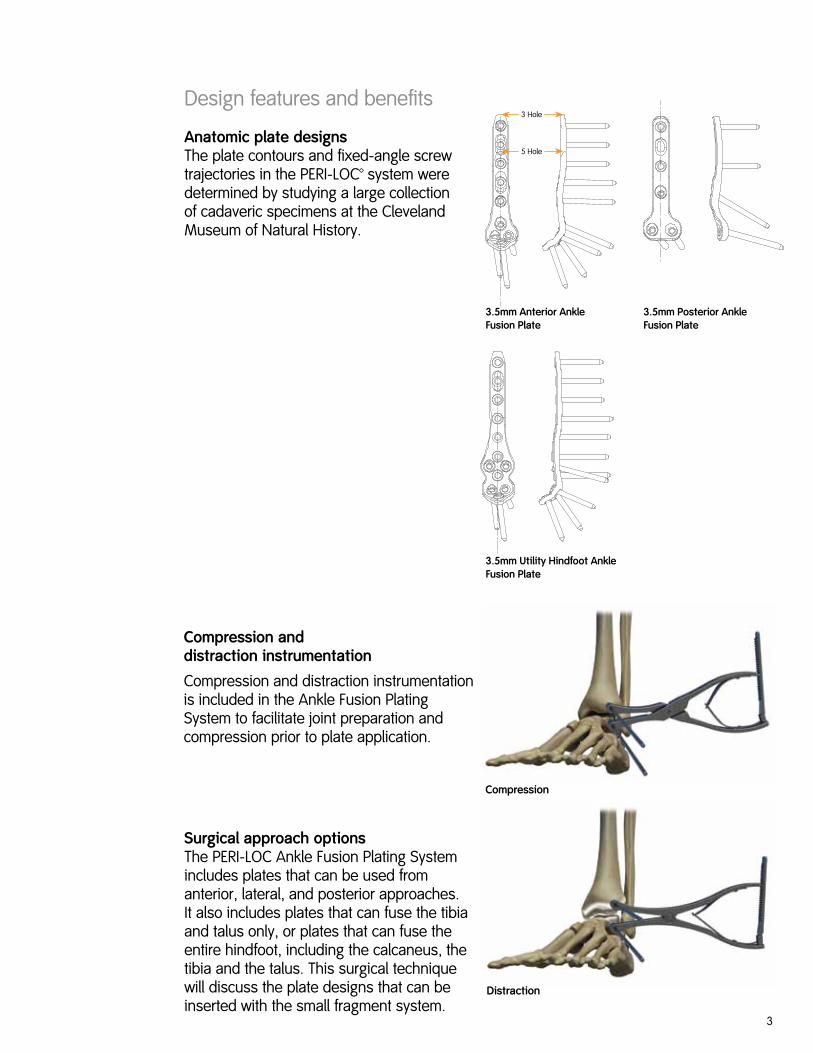
Anatomic plate designs The plate contours and fixed-angle screw trajectories in the PERI-LOC™ system were determined by studying a large collection of cadaveric specimens at the Cleveland Museum of Natural History.
Surgical approach options The PERI-LOC Ankle Fusion Plating System includes plates that can be used from anterior, lateral, and posterior approaches. It also includes plates that can fuse the tibia and talus only, or plates that can fuse the entire hindfoot, including the calcaneus, the tibia and the talus. This surgical technique will discuss the plate designs that can be inserted with the small fragment system.
Compression and distraction instrumentation
Compression and distraction instrumentation is included in the Ankle Fusion Plating System to facilitate joint preparation and compression prior to plate application.
Design features and benefits3 Hole
5 Hole
3.5mm Anterior Ankle Fusion Plate
3.5mm Utility Hindfoot Ankle Fusion Plate
3.5mm Posterior Ankle Fusion Plate
Compression
Distraction

4
System overview
The 3.5mm Ankle and Hindfoot Fusion Plates are inserted with the PERI-LOC™ Small Fragment instruments and implants in addition to the ankle fusion instruments. The Small Fragment Surgical Technique (7118-1685) can be used to provide supplemental information regarding the instrument system. The sets needed for a small fragment ankle fusion case are listed below.
Note Either 4.0mm Cancellous or 4.0mm Cannulated Screws are available in the Small Fragment System
Small Fragment Implant and Instrument Sets
Ankle Fusion Instrument Set
Ankle Fusion Implant Set

5
Anterior Primary Plates• Designed to fuse the tibia and talus from an
anterior approach
• Anatomically contoured for optimal fit
• Plates fit 3.5mm Locking and Cortex Screws as well as 4.0mm Cancellous and Cannulated Screws*
• Plates are left/right specific
• Available in three (67mm) and five (92mm) hole lengths
Implant overview
Hindfoot Ankle Utility Plates
Plate dimensions
Profile thickness 3.8mm
Width of head 23.2mm
Width of shaft 10.6mm
Shaft hole spacing 12.7mm
Plate length 104mm
Anterior Primary Plates
Plate dimensions
Profile thickness 3.8mm
Width of head 21.8mm
Width of shaft 10.6mm
Shaft hole spacing 12.7mm
Plate length 3 hole: 67mm
5 hole: 92mm
Posterior Plates
Plate dimensions
Profile thickness 3.8mm–5.3mm
Width of head 24.4mm
Width of shaft 11.0mm
Plate length 80mm
*4.0mm Cannulated Screw can be inserted through the plate with the use of an adapter washer.
Width
Length
Posterior Plates• Anatomically pre-contoured for optimal fit
• Plates fit 3.5mm Locking and Cortex Screws as well as 4.0mm Cancellous and Cannulated Screws*
• Plates are left/right specific
• Available in three hole length (80mm)
Hindfoot Ankle Utility Plates• Designed to perform fusions from two
different approaches
• Anterior approach
- Can be used to fuse the tibia and talus
- Cluster of screws target into graft used to fill talar void
• Posterior approach
- Can be used to fuse the tibia, talus and calcaneus
• Anatomically contoured for optimal fit
• Plates fit 3.5mm Locking and Cortex screws as well as 4.0mm Cancellous and Cannulated Screws*
• Plates are left/right specific
• Available in five (104mm) hole length
Anterior Primary Plate
Anterior placementof Hindfoot AnkleUtility Plate
Posterior placementof Hindfoot AnkleUtility Plate
Posterior Plate

6
3.5mm T20 Cortex Screws• Aggressive self-tapping cutting flutes for ease of
insertion in dense cortical bone
• T20 recess accepts self-retaining T20 driver
3.5mm T20 Locking Screws• Aggressive self-tapping cutting flutes for ease of
insertion in dense cortical bone
• Head of locking screw has a triple-lead thread to facilitate ease of insertion
• T20 recess accepts self-retaining T20 driver
3.5mm T20 Cortex Screws
Screw dimensions
Head height 3.0mm
Head outer diameter 6.8mm
Driver size T20
Thread outer diameter 3.5mm
Core diameter 2.7mm
Thread pitch 1.25mm
Number of Self-tapping flutes
3
3.5mm T20 Locking Screws
Screw dimensions
Head height 3.2mm
Head outer diameter 6.8mm
Driver size T20
Thread outer diameter 3.5mm
Core diameter 2.7mm
Thread pitch 1.25mm
Number of Self-tapping flutes
3

7
4.0mm T20 Cancellous Screws
Screw dimensions
Head height 3.3mm
Head outer diameter 6.8mm
Driver size T20
Thread outer diameter 4.0mm
Core diameter 1.9mm
Thread pitch 1.75mm
Number of Self-tapping flutes
NA
4.0mm Cannulated Screws
Screw dimensions
Head height 2.9mm
Head outer diameter 6.0mm
Driver size 2.5mm
Thread outer diameter 4.0mm
Core diameter 2.7mm
Thread pitch 1.8mm
4.0mm T20 Cancellous Screws• Available fully threaded or partially threaded
• Designed to be used inside or outside of the plate at the surgeon’s discretion
• T20 recess accepts self-retaining T20 driver
4.0mm Cannulated Screws• Available partially threaded
• Self-drilling, self-tapping design
• Can be used through a locking hole with the 4.0mm Cannulated Screw Adapter
• 1.3mm cannulation

8
Surgical technique
Anterior approachThe patient should be positioned supine on a radiolucent table with a bump under the ipsilateral hip.
An anterior incision is made and dissection is carried out between the extensor hallucis longus and tibialis anterior tendons. The incision is typically begun approximately 10cm proximal to the ankle joint, and continued as a straight incision to the level of the talonavicular joint. The neurovascular bundle is identified and retracted laterally. Care must be taken not to injure sensory nerve branches at the distal extent of the incision. The joint capsule is opened and minimal periosteal stripping is performed.
Posterior approachEither a posterolateral or direct posterior midline approach can be used for this procedure. With both approaches, care must be taken to avoid injury to the tibial nerve and artery by staying lateral to the flexor hallucis longus.
Posterolateral approachThe patient may be positioned lateral or prone on a radiolucent table. A posterolateral incision is made between the posterior border of the fibula and the lateral border of the achilles tendon, starting level with the tip of the fibula and working proximally. The sural nerve and short saphenous vein should be protected anterior to the incision. The peroneal retinaculum is divided, the peroneal tendons are retracted laterally, and the flexor hallucis longus is mobilized medially. Dissection is continued through the interval of the flexor hallucis longus and the peroneal tendons, down to the posterior ankle joint.
9
Direct posterior midline approach The patient should be positioned prone on a radiolucent table. A direct midline approach is used, and the Achilles tendon is split by performing a Z-shaped cut. To better visualize the joint, a partial posterior malleolar excision can be performed. Both the ankle and subtalar joints are easily visualized with this technique. The Achilles tendon should be repaired at the conclusion of the case if this method is selected.
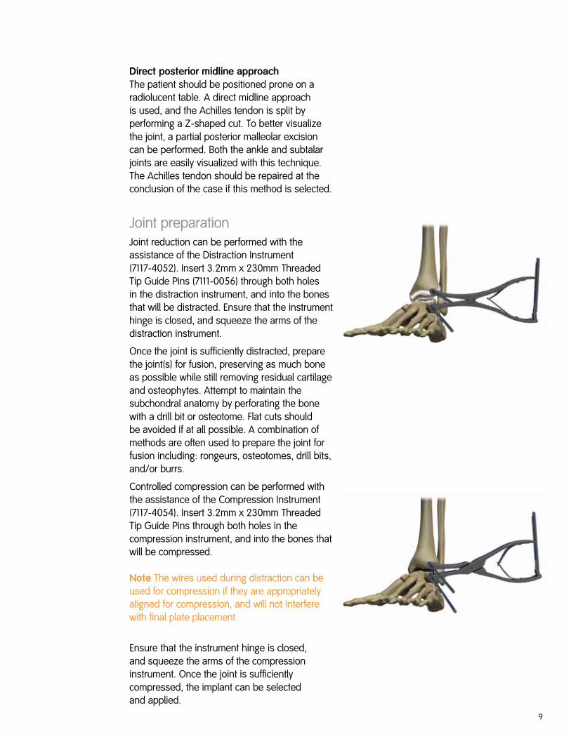
Joint preparationJoint reduction can be performed with the assistance of the Distraction Instrument (7117-4052). Insert 3.2mm x 230mm Threaded Tip Guide Pins (7111-0056) through both holes in the distraction instrument, and into the bones that will be distracted. Ensure that the instrument hinge is closed, and squeeze the arms of the distraction instrument.
Once the joint is sufficiently distracted, prepare the joint(s) for fusion, preserving as much bone as possible while still removing residual cartilage and osteophytes. Attempt to maintain the subchondral anatomy by perforating the bone with a drill bit or osteotome. Flat cuts should be avoided if at all possible. A combination of methods are often used to prepare the joint for fusion including: rongeurs, osteotomes, drill bits, and/or burrs.
Controlled compression can be performed with the assistance of the Compression Instrument (7117-4054). Insert 3.2mm x 230mm Threaded Tip Guide Pins through both holes in the compression instrument, and into the bones that will be compressed.
Note The wires used during distraction can be used for compression if they are appropriately aligned for compression, and will not interfere with final plate placement.
Ensure that the instrument hinge is closed, and squeeze the arms of the compression instrument. Once the joint is sufficiently compressed, the implant can be selected and applied.

10
Implant selectionSelect the fusion plate that corresponds to the correct approach, anatomy and procedure. Metal templates are available to verify that the implant will fit the patient as expected.

11
Arthrodesis reduction/ plate positioning
PERI-LOC™ Reduction Instruments The plate can be provisionally fixed to the bone using the PF Pins and Reduction Clamps available in the small fragment instrument tray. In addition, various distraction and compression clamps can be used to assist with joint preparation and placement.
Reduction ForcepsReduction Forceps with Points, Broad
7117-3377
Reduction Forceps with Serrated Jaw
7117-3378
Provisional Fixation Pins2.7mm x 14mm 7117-35822.7mm x 25mm 7117-35832.7mm x 40mm 7117-0812
K-Wires1.25mm x 150mm 7116-10121.6mm x 150mm 7116-10162.0mm x 150mm 7116-1020
Note These Provisional Fixation Pins are designed to be used with the 2.7mm Locking Drill Guide. This allows the provisional fixation pin to be placed in the center of the locking screw hole. Once the provisional fixation pin is removed, either a 3.5mm Cortex or a 3.5mm Locking Screw can be used in the same hole. Provisional fixation pins may be inserted on power, but final seating should be performed by hand to avoid stripping of the threads and loss of purchase.

12
Screw insertion
The choice of screws, and the order and configuration, is a decision to be made by the individual surgeon depending on the patient’s circumstances and needs. Smith & Nephew does not recommend any particular screw insertion order or configuration of the various types of screws available in the system.
3.5mm Cortex Screws3.5mm Cortex Screws may be used in either neutral or compression mode. Neutral mode will place the screw directly in the center of the screw hole and is ideal when axial compression is not desired. Compression mode will place the screw eccentrically in the screw hole and allow the screw head to travel down the ramped hole so that axial compression is achieved during final seating. Each screw hole allows for 1mm of axial compression. If desired, distraction or translation can also be achieved using this technique.
Drill (neutral mode) Position the neutral side (green) of the 2.7mm Neutral x 2.7mm Compression Drill Guide (7117-3570) into the desired screw hole. Drill to the desired depth using the 2.7mm Drill Bit (7117-3502).
Drill (compression mode) Insert the compression side (yellow) of the 2.7mm Neutral x 2.7mm Compression Drill Guide (7117-3570) into the desired screw hole. To gain axial compression, position the drill guide in the desired screw hole so that it is against the wall of the hole furthest away from the fusion. Drill to the desired depth using the 2.7mm Drill Bit (7117-3502).

13
Measure Measure for screw length by using the 3.5mm Screw Depth Gauge (7117-3534).
Screw insertion Insert the appropriate length 3.5mm Cortex Screw using the T20 Self Retaining Screwdriver (7117-3592). This should be done manually using the Large Screwdriver Handle (7117-3547).
Note In the event that a 3.5mm Cortex screw needs to be used outside the plate for interfragmentary compression, the Small Fragment instrumentation set includes a 2.7mm Drill Guide Insert (7117-3590) to assist with lag screw technique. This 2.7mm Drill Guide Insert is used in conjunction with the 3.5mm side of the 2.7mm x 3.5mm Drill Guide (7117-3572).

14
3.5mm Locking ScrewsThere are two techniques that can be used to insert 3.5mm Locking Screws. If using a percutaneous technique, the 3.5mm Locking Screw Guide (7117-3538) with the 2.7mm Locking Drill Guide Insert (7117-3529) will provide a channel through the soft tissue to insert screws. This option also ensures correct screw trajectory in osteopenic bone. However, this two-piece assembly drill guide may be substituted with the one-piece 2.7mm Locking Drill Guide (7117-3450). This is a one-piece drill guide and may be found easier to thread into the locking holes located on highly contoured areas of the plate.
Using the 3.5mm Locking Screw Guide with the 2.7mm Locking Drill Guide Insert
Note This option may only be used with screws longer than 24mm. If the screw is 24mm or shorter, use the 2.7mm Locking Drill Guide.
Drill
Thread the 3.5mm Locking Screw Guide (7117-3538) with the 2.7mm Locking Drill Guide Insert (7117-3529) into the threaded hole. Drill to the desired depth using the 2.7mm Drill Bit (7117-3503).
Measure
Measure for screw length by reading the exposed calibrations off the drill bit. If the measurement is longer than 24mm proceed with the described technique. If the measurement is 24mm or shorter, remove the 3.5mm Locking Screw Guide and insert the screw without the guide.
15
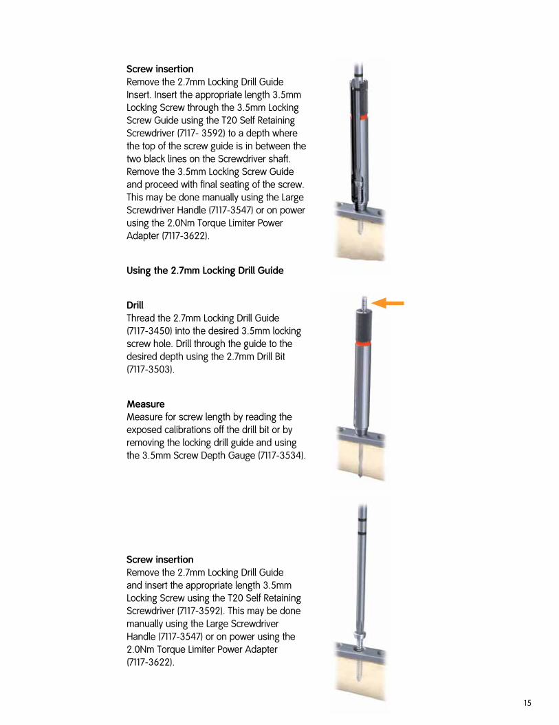
Screw insertion Remove the 2.7mm Locking Drill Guide Insert. Insert the appropriate length 3.5mm Locking Screw through the 3.5mm Locking Screw Guide using the T20 Self Retaining Screwdriver (7117- 3592) to a depth where the top of the screw guide is in between the two black lines on the Screwdriver shaft. Remove the 3.5mm Locking Screw Guide and proceed with final seating of the screw. This may be done manually using the Large Screwdriver Handle (7117-3547) or on power using the 2.0Nm Torque Limiter Power Adapter (7117-3622).
Using the 2.7mm Locking Drill Guide
Drill Thread the 2.7mm Locking Drill Guide (7117-3450) into the desired 3.5mm locking screw hole. Drill through the guide to the desired depth using the 2.7mm Drill Bit (7117-3503).
Measure Measure for screw length by reading the exposed calibrations off the drill bit or by removing the locking drill guide and using the 3.5mm Screw Depth Gauge (7117-3534).
Screw insertion Remove the 2.7mm Locking Drill Guide and insert the appropriate length 3.5mm Locking Screw using the T20 Self Retaining Screwdriver (7117-3592). This may be done manually using the Large Screwdriver Handle (7117-3547) or on power using the 2.0Nm Torque Limiter Power Adapter (7117-3622).

16
4.0mm Cancellous ScrewsThe PERI-LOC™ Small Fragment Instrument and Implant Set features an optional 4.0mm Cancellous Screw Caddy. This may be replaced with the 4.0mm Cannulated Screw Caddy depending on the individual surgeon preference. The 4.0mm Cancellous Screws may be used through the plate or outside of the plate for joint surface reduction.
Drill (through the plate) Position the neutral side of the 2.7mm Neutral x 2.7mm Compression Drill Guide (7117-3570) into the desired screw hole. Drill to the desired depth using the 2.7mm Drill Bit (7117-3502).
Drill (outside the plate) Position the 2.7mm side of the 2.0mm x 2.7mm Drill Guide (7117-3571) against the bone. Drill to the desired depth using the 2.7mm Drill Bit (7117-3502).
Countersink (if outside the plate) Countersinking the head will reduce implant profile. Prepare the bone surface by placing the Small Fragment Countersink (7117-3344) into the predrilled hole and turn to the right. Do not countersink on power. This should be performed manually using the Small T-Handle (7117-3542).

17
Measure
Measure for screw length by using the 3.5mm Depth Gauge (7117-3534).
Tap (optional)
In areas of increased bone density, it may be beneficial to tap prior to screw insertion. Tap by using the 4.0mm Cancellous Tap (7117-3386). This should be performed manually using the Small T-Handle (7117-3542).
Screw insertion Insert the appropriate length 4.0mm Cancellous Screw using the T20 Self Retaining Screwdriver (7117-3592). This should be done manually using the Large Screwdriver Handle (7117-3547).

18
Drill (optional) Due to the self-drilling tip of the 4.0mm Cannulated Screws, it is not necessary to drill prior to screw insertion. However, in areas of increased bone density, drilling prior to screw insertion may be beneficial. Using the 2.7mm side of the 1.3mm x 2.7mm Drill Guide (7117-3576) as a soft tissue protector, insert the 2.7mm Cannulated Drill Bit (7117-3581) over the guide pin. Drill to the desired depth.
Tip Drilling 5mm short of the screw measurement prevents the drill from engaging the threaded tip of the pin, avoiding inadvertent guide pin removal.
4.0mm Cannulated Screws(Outside the plate) Guide pin insertion Position the 1.3mm side of the 1.3mm x 2.7mm Drill Guide (7117-3576) against the bone. Insert a 1.3mm Guide Pin (12-8047) through the drill guide to the desired depth.
Countersink Countersinking the head will reduce implant profile. Prepare the bone surface by placing the 1.3mm Cannulated Countersink (7117-7188) over the guide pin and against the bone and turn to the right. Do not countersink on power. This should be performed manually using the Small T-Handle (7117-3542).
Measure Place the K-Wire Direct Measuring Gauge over the wire and against the bone. Measure for screw length by reading the exposed calibrations on the gauge.

19
4.0mm Cannulated Screws (through the plate)In the event that a 4.0mm Cannulated Screw is required to be placed through a locking plate, a 4.0mm Cannulated Screw Adapter (7380-1012) is required.
Adapter insertion Using the 4.7mm Cannulated Hexdriver (7117-3579), remove a Cannulated Screw Adapter from the 4.0mm Cannulated Screw Caddy. Hand tighten the adapter into the appropriate locking plate hole. Follow the same technique for inserting a 4.0mm Cannulated Screw outside of the plate, described within this document.
Note When using a 4.0mm Cannulated Screw through a locking plate hole, the head of the screw will make contact with the Cannulated Screw Adapter, rather than the plate. To account for this, add 1mm to the measurement displayed on the K-Wire Direct Measuring Gauge.
Tap (optional) In areas of increased bone density, it may be beneficial to tap prior to screw insertion. Tap by using the 4.0mm Cannulated Tap (7117-3584). This should be performed manually using the Small T-Handle (7117-3542).
Screw Insertion Load the appropriate length 4.0mm Cannulated Screw onto the 2.5mm Cannulated Hexdriver (7117-3580) with Holding Sleeve (7117-0031) and insert over the guide pin into the bone. This should be performed manually with the Large Screwdriver Handle (7117-3547).

20
Catalog information PERI-LOC™ Ankle Fusion Plating System
Ankle Fusion Instrument SetSet No. 7117-0150
Cat No. Description Qty
7111-0056 3.2mm X 230mm Threaded Tip Guide Pin 4
7111-1022 3.5mm Ankle Fusion Plate, Anterior Primary, Right, 3 Hole, 67mm Template 1
7111-1023 3.5mm Ankle Fusion Plate, Anterior Primary, Left, 3 Hole, 67mm Template 1
7111-1024 3.5mm Ankle Fusion Plate, Anterior Primary, Right, 5 Hole, 92mm Template 1
7111-1025 3.5mm Ankle Fusion Plate, Anterior Primary, Left, 5 Hole, 92mm Template 1
7111-1028 3.5mm Hindfoot Ankle Fusion Utility Plate, Right, 5 Hole, 104mm Template 1
7111-1029 3.5mm Hindfoot Ankle Fusion Utility Plate, Left, 5 Hole, 104mm Template 1
7111-1030 4.5mm Ankle Fusion Plate Lateral Tibiotalocalcaneal, Right, 120mm Template 1
7111-1031 4.5mm Ankle Fusion Plate Lateral Tibiotalocalcaneal, Left, 120mm Template 1
7111-1034 3.5mm Ankle Fusion Plate Posterior, Right, 80mm Template 1
7111-1035 3.5mm Ankle Fusion Plate Posterior, Left, 80mm Template 1
7117-4052 Distraction Instrument 1
7117-4054 Compression Instrument 1
7117-4060 Ankle Fusion Instrument Tray 1
7117-4061 Ankle Fusion Instrument Tray Lid 1

21
Ankle Fusion Implant SetSet No. 7282-6050
Cat No. Description Qty
7282-1030S 4.5mm Ankle Fusion Plate, Lateral Tibiotalocalcaneal, Right, 120mm, Sterile 1
7282-1031S 4.5mm Ankle Fusion Plate, Lateral Tibiotalocalcaneal, Left, 120mm, Sterile 1
7282-1034S 3.5mm Ankle Fusion Plate, Posterior, Right, 80mm, Sterile 1
7282-1035S 3.5mm Ankle Fusion Plate, Posterior, Left, 80mm, Sterile 1
7282-1042S 3.5mm Ankle Fusion Plate Anterior Primary Compression Slot, Right, 3 Hole, 67mm, Sterile 1
7282-1043S 3.5mm Ankle Fusion Plate Anterior Primary Compression Slot, Left, 3 Hole, 67mm, Sterile 1
7282-1044S 3.5mm Ankle Fusion Plate Anterior Primary Compression Slot, Right, 5 Hole, 92mm, Sterile 1
7282-1045S 3.5mm Ankle Fusion Plate Anterior Primary Compression Slot, Left, 5 Hole, 92mm, Sterile 1
7282-1046S 3.5mm Hindfoot Ankle Fusion Utility Plate Compression Slot, Right, 5 Hole, 104mm, Sterile 1
7282-1047S 3.5MM Hindfoot Ankle Fusion Utility Plate Compression Slot, Left, 5 Hole, 104mm, Sterile 1
7117-4045 PERI-LOC™ Ankle Fusion Implant and Disposable Box 1

22
Small Fragment Instrument SetSet No. 7181-0500
Cat No. Description Qty
7117-0057 Hohmann Retractor, 8mm 2
7117-3369 Hohmann Rectractor, 8mm, Bent 2
7117-0095 Hohmann Retractor, 15mm 2
7117-3377 Reduction Forceps with Points, Broad 2
7117-3378 Reduction Forceps with Serrated Jaw 2
7117-3576 1.3mm x 2.7mm Drill Guide 1
7117-3571 2.0mm x 2.7mm Drill Guide 1
7117-3570 2.7mm Neutral/2.7mm Compression Drill Guide
1
7117-3594 2.7mm Neutral Slot Drill Guide 1
7117-3572 2.7mm x 3.5mm Drill Guide 1
7117-3589 2.0mm Drill Guide Insert 1
7117-3590 2.7mm Drill Guide Insert 1
7117-3491 2.0mm K-Wire Locking Guide, One Piece 1
7117-3448 2.0mm Locking Drill Guide 1
7117-3450 2.7mm Locking Drill Guide 1
7117-3452 2.7mm Locking Screw Guide 1
7117-3538 3.5mm Locking Screw Guide 1
7117-3449 2.0mm Locking Drill Guide Insert 1
7117-3529 2.7mm Locking Drill Guide Insert 1
7117-3525 2.7mm Screw Depth Gauge 1
7117-3523 3.5mm Short Screw Depth Gauge 1
7117-3534 3.5mm Screw Depth Gauge 1
7111-7083 4.0mm Cannulated Direct Measuring Device
1
7117-3614 T15 Self-retaining Screwdriver Shaft, 120mm
1
7117-3585 T15 Self-retaining Screwdriver Shaft, 178mm
1
7117-3592 T20 Self-retaining Screwdriver Shaft, 120mm
1
Cat No. Description Qty
7117-3593 T20 Self-retaining Screwdriver Shaft, 178mm
1
7117-3637 T20 Self Retaining Screwdriver 1
7117-3580 2.5mm Cannulated Hexdriver Shaft, 120mm
1
7117-3535 2.5mm Hexdriver Shaft w/Quick Connect 1
7117-3537 3.5mm Hexdriver Shaft w/Quick Connect 1
7117-3579 4.7mm Cannulated Hexdriver Shaft, 127mm
1
7117-3612 T20 Removal Screwdriver Shaft, 178mm 1
7117-3613 T15 Removal Screwdriver Shaft, 178mm 1
7117-3542 Small T-Handle, Quick Coupling 1
7117-3543 Tear Drop Screwdriver Handle 1
7117-3547 Large Screwdriver Handle 1
7117-0031 Holding Sleeve 1
7117-0043 Sharp Hook 1
7117-0045 Screw Forceps 1
7117-3613 T15 Removal Screwdriver Shaft, 178mm 1
7117-3542 Small T-Handle, Quick Coupling 1
7117-3543 Tear Drop Screwdriver Handle 1
7117-3547 Large Screwdriver Handle 1
7117-0031 Holding Sleeve 1
7117-0063 Wire Bending Pliers 1
7117-3544 Reverse Verbrugge, 190mm 1
7117-0097 Curved Periosteal Elevator, 6mm 1
7117-3344 Small Fragment Countersink 1
7117-3528 Cannulated AO to Trinkle Adapter 1
7117-3622 2.0Nm Torque Limiter Adapter 1
7117-3636 Small Fragment Bending Irons 2
Catalog information PERI-LOC™ Small Fragment System

23
Trays and CaddiesCat. No. Description Qty
7117-0650 Basic Instrument Tray 1
7117-0654 Screw Caddy 1
7117-0655 Screw Caddy Lid 1
Cat No. Description Qty
7117-0657 Plate Caddy 1
7117-0659 Instrument and Implant Set Tray 1
7117-0660 Instrument and Implant Set Tray Lid 1
Drill Guide Provisional Fixation PinsCat. No. Description Qty
7117-3582 2.7mm Drill Guide PF Pin, 14mm 2
7117-3583 2.7mm Drill Guide PF Pin, 25mm 2
7117-0812 2.7mm Drill Guide PF Pin, 40mm 2
K-Wires and Guide PinsCat. No. Description Qty
128047 1.3 x 140mm Guide Pin 1
7116-1012 1.25mm K-Wire 1
7116-1016 1.6mm K-Wire 1
7116-1020 2.0mm K-Wire 1
Small Fragment Disposables SetSet No. 7181-0417
Taps with Quick ConnectCat. No. Description Qty
7117-3366 2.7mm Tap 1
7117-3318 3.5mm Tap 1
7117-3386 4.0mm Cancellous Tap 1
7117-3584 4.0mm Cannulated Tap 1
Calibrated Drills with Quick ConnectCat. No. Description Qty
7117-3501 2.0mm Drill 1
7117-3502 2.7mm Short Drill 2
7117-3503 2.7mm Drill 2
7117-3581 3.5mm Short Drill 1
7117-3504 2.7mm Cannulated Drill, 155mm 1

24
Small Fragment Screw SetSet No. 7181-0420
2.7mm T15 Cortex Screws, Self-tapping
2.7mm T15 Locking Screws, Self-tapping
Cat No. Description Qty
7382-3010 10mm 4
7382-3012 12mm 4
7382-3014 14mm 4
7382-3016 16mm 4
7382-3018 18mm 2
7382-3020 20mm 2
7382-3022 22mm 2
7382-3024 24mm 2
7382-3026 26mm 2
7382-3028 28mm 2
7382-3030 30mm 2
7382-3032 32mm 2
7382-3034 34mm 2
Cat No. Description Qty
7382-2310 10mm 6
7382-2312 12mm 6
7382-2314 14mm 6
7382-2316 16mm 6
7382-2318 18mm 6
7382-2320 20mm 6
7382-2322 22mm 3
7382-2324 24mm 3
7382-2326 26mm 3
7382-2328 28mm 3
7382-2330 30mm 3
7382-2332 32mm 3
Cat No. Description Qty
7382-3036 36mm 2
7382-3038 38mm 2
7382-3040 40mm 4
7382-3042 42mm 4
7382-3044 44mm 4
7382-3046 46mm 4
7382-3048 48mm 4
7382-3050 50mm 4
7382-3055 55mm 4
7382-3060 60mm 2
7380--3065 65mm 0
7380--3070 70mm 0
Cat No. Description Qty
7382-2334 34mm 3
7382-2336 36mm 3
7382-2338 38mm 3
7382-2340 40mm 6
7382-2342 42mm 6
7382-2344 44mm 6
7382-2346 46mm 6
7382-2348 48mm 6
7382-2350 50mm 6
7382-2355 55mm 6
7382-2360 60mm 3
Catalog information PERI-LOC™ Small Fragment System

25
3.5mm T20 Cortex Screws, Self-tapping
3.5mm T20 Locking Screws, Self-tapping
Cat No. Description Qty
7382-4010 10mm 8
7382-4012 12mm 8
7382-4014 14mm 8
7382-4016 16mm 8
7382-4018 18mm 8
7382-4020 20mm 4
7382-4022 22mm 4
7382-4024 24mm 4
7382-4026 26mm 4
7382-4028 28mm 4
7382-4030 30mm 4
7382-4032 32mm 4
7382-4034 34mm 4
7382-4036 36mm 4
7382-4038 38mm 4
7382-4040 40mm 4
7382-4042 42mm 4
Cat No. Description Qty
7382-5010 10mm 8
7382-5012 12mm 8
7382-5014 14mm 8
7382-5016 16mm 8
7382-5018 18mm 8
7382-5020 20mm 4
7382-5022 22mm 4
7382-5024 24mm 4
7382-5026 26mm 4
7382-5028 28mm 4
7382-5030 30mm 4
7382-5032 32mm 4
7382-5034 34mm 4
7382-5036 36mm 4
7382-5038 38mm 4
7382-5040 40mm 4
7382-5042 42mm 4
Cat No. Description Qty
7382-4044 44mm 4
7382-4046 46mm 4
7382-4048 48mm 4
7382-4050 50mm 4
7382-4055 55mm 4
7382-4060 60mm 4
7380-4065 65mm 0
7380-4070 70mm 0
7380-4075 75mm 0
7380-4080 80mm 0
7380-4085 85mm 0
7380-4090 90mm 0
7380-4095 95mm 0
7380-4100 100mm 0
7380-4105 105mm 0
7380-4110 110mm 0
Cat No. Description Qty
7382-5044 44mm 4
7382-5046 46mm 4
7382-5048 48mm 4
7382-5050 50mm 4
7382-5055 55mm 4
7382-5060 60mm 4
7380-5065 65mm 0
7380-5070 70mm 0
7380-5075 75mm 0
7380-5080 80mm 0
7380-5085 85mm 0
7380-5090 90mm 0
7380-5095 95mm 0
7380-5100 100mm 0
7380-5105 105mm 0
7380-5110 110mm 0
Washer
Cat. No. Description Qty
7114-3107 7.0mm Outer Diameter 6

26
4.0mm Cancellous Screw SetSet No. 7181-5200
4.0mm T20 Cancellous Screws, Fully Threaded
4.0mm T20 Cancellous Screws, Partially Threaded
Cat No. Description Qty
7382-5210 10mm 2
7382-5212 12mm 2
7382-5214 14mm 2
7382-5216 16mm 2
7382-5218 18mm 2
7382-5220 20mm 2
7382-5222 22mm 2
7382-5224 24mm 2
7382-5226 26mm 2
7382-5228 28mm 2
7382-5230 30mm 2
7382-5232 32mm 2
7382-5234 34mm 2
7382-5236 36mm 2
Cat No. Description Qty
7382-5310 10mm 2
7382-5312 12mm 2
7382-5314 14mm 2
7382-5316 16mm 2
7382-5318 18mm 2
7382-5320 20mm 2
7382-5322 22mm 2
7382-5324 24mm 2
7382-5326 26mm 2
7382-5328 28mm 2
7382-5330 30mm 2
7382-5335 35mm 2
7382-5340 40mm 2
Cat No. Description Qty
7382-5238 38mm 2
7382-5240 40mm 2
7382-5245 45mm 2
7382-5250 50mm 2
7382-5255 55mm 2
7382-5260 60mm 2
7380--5265 65mm 0
7380--5270 70mm 0
7380--5275 75mm 0
7380--5280 80mm 0
7380--5285 85mm 0
7380--5290 90mm 0
7380--5295 95mm 0
7380--5300 100mm 0
Cat No. Description Qty
7382-5345 45mm 2
7382-5350 50mm 2
7382-5355 55mm 2
7382-5360 60mm 2
7380-5365 65mm 0
7380-5370 70mm 0
7380-5375 75mm 0
7380-5380 80mm 0
7380-5385 85mm 0
7380-5390 90mm 0
7380-5395 95mm 0
7380-5400 100mm 0
4.0mm Cancellous Screw CaddiesCat. No. Description Qty
7117-0680 4.0mm Cancellous Screw Caddy 1
7117-0681 4.0mm Cancellous Screw Caddy Lid 1
Catalog information PERI-LOC™ Small Fragment System

27
4.0mm Cannulated Screw Set, Partially ThreadedSet No. 7181-1800
4.0mm Cannulated Screws, Partially Threaded
Cat No. Description Qty
121810 10mm 2
121812 12mm 2
121814 14mm 2
121816 16mm 2
121818 18mm 2
121820 20mm 2
121822 22mm 2
121824 24mm 2
121826 26mm 2
121828 28mm 2
121830 30mm 2
121832 32mm 2
121834 34mm 2
Cat No. Description Qty
121836 36mm 2
121838 38mm 2
121840 40mm 2
121842 42mm 2
121844 44mm 2
121846 46mm 2
121848 48mm 2
121850 50mm 2
121852 52mm 2
121854 54mm 2
121856 56mm 2
121858 58mm 2
121860 60mm 2
CaddiesCat. No. Description Qty
7117-0686 4.0mm Partially Threaded Cannulated Screw Caddy 1
7117-0687 4.0mm Partially Threaded Cannulated Screw Caddy Lid 1

28
Notes


Smith & Nephew, Inc.7135 Goodlett Farms ParkwayCordova, TN 38016USA
Telephone: 1-901-396-2121Information: 1-800-821-5700Orders/Inquiries: 1-800-238-7538
www.smith-nephew.com
™Trademark of Smith & Nephew. Reg. US Pat. & TM Off. ©2012 Smith & Nephew, Inc. All rights reserved.7118-1943 REV0.1 06/12