
Animatronic Shader Lamps Avatars - cs.unc.eduwelch/media/pdf/Lincoln2009ac.pdf · Animatronic...
7
Animatronic Shader Lamps Avatars Peter Lincoln Greg Welch Andrew Nashel Adrian Ilie Andrei State Henry Fuchs The University of North Carolina at Chapel Hill Department of Computer Science * network a c b d Figure 1: The upper images conceptually illustrate one possible use of animatronic Shader Lamps Avatars (SLA): full-duplex telepresence for medical consultation. The physician in (a) interacts with a remote patient and therapist in (b) by means of a camera-equipped SLA. The SLA allows the physician to both see and be seen by the patient and therapist. The lower two figures show our current uni-directional proof-of-concept prototype. The user in (c) wears a tracking system and is imaged by a video camera. In (d) we show the avatar of the user, consisting of a styrofoam head mounted on a pan-tilt unit and illuminated by a projector. ABSTRACT Applications such as telepresence and training involve the display of real or synthetic humans to multiple viewers. When attempting to render the humans with conventional displays, non-verbal cues such as head pose, gaze direction, body posture, and facial expres- sion are difficult to convey correctly to all viewers. In addition, a framed image of a human conveys only a limited physical sense of presence—primarily through the display’s location. While progress continues on articulated robots that mimic humans, the focus has been on the motion and behavior of the robots. * e-mail: {plincoln, welch, nashel, adyilie, andrei, fuchs}@cs.unc.edu We introduce a new approach for robotic avatars of real people: the use of cameras and projectors to capture and map the dynamic motion and appearance of a real person onto a humanoid anima- tronic model. We call these devices animatronic Shader Lamps Avatars (SLA). We present a proof-of-concept prototype comprised of a camera, a tracking system, a digital projector, and a life-sized styrofoam head mounted on a pan-tilt unit. The system captures imagery of a moving, talking user and maps the appearance and motion onto the animatronic SLA, delivering a dynamic, real-time representation of the user to multiple viewers. Index Terms: H.4.3 [Information Systems Applications]: Com- munications Applications—Computer conferencing, teleconferenc- ing, and videoconferencing H.5.1 [Multimedia Information Sys- tems]: Animations—Artificial, augmented, and virtual realities I.3.7 [Computer Graphics]: Three Dimensional Graphics and Realism—Virtual Reality; I.3.8 [Computer Graphics]: Applica- tions;
Transcript of Animatronic Shader Lamps Avatars - cs.unc.eduwelch/media/pdf/Lincoln2009ac.pdf · Animatronic...
Animatronic Shader Lamps AvatarsPeter Lincoln Greg Welch Andrew Nashel Adrian Ilie Andrei State Henry Fuchs
The University of North Carolina at Chapel HillDepartment of Computer Science∗
network
a
c
b
d
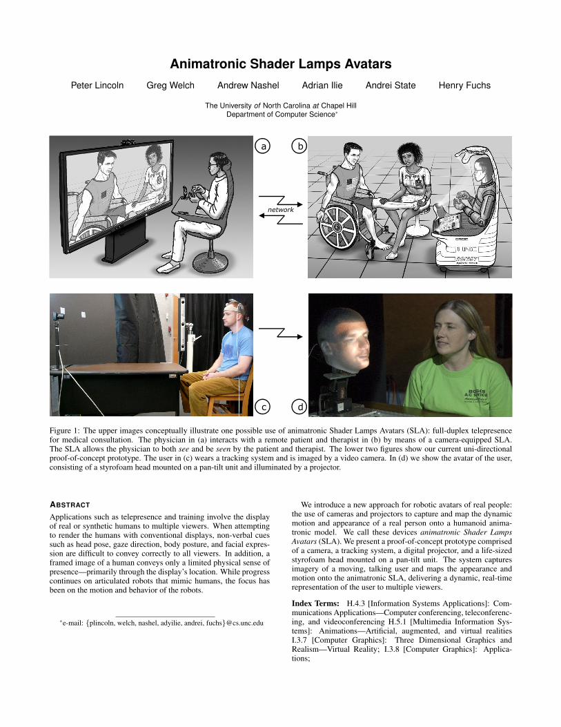
Figure 1: The upper images conceptually illustrate one possible use of animatronic Shader Lamps Avatars (SLA): full-duplex telepresencefor medical consultation. The physician in (a) interacts with a remote patient and therapist in (b) by means of a camera-equipped SLA.The SLA allows the physician to both see and be seen by the patient and therapist. The lower two figures show our current uni-directionalproof-of-concept prototype. The user in (c) wears a tracking system and is imaged by a video camera. In (d) we show the avatar of the user,consisting of a styrofoam head mounted on a pan-tilt unit and illuminated by a projector.
ABSTRACT
Applications such as telepresence and training involve the displayof real or synthetic humans to multiple viewers. When attemptingto render the humans with conventional displays, non-verbal cuessuch as head pose, gaze direction, body posture, and facial expres-sion are difficult to convey correctly to all viewers. In addition, aframed image of a human conveys only a limited physical sense ofpresence—primarily through the display’s location. While progresscontinues on articulated robots that mimic humans, the focus hasbeen on the motion and behavior of the robots.
∗e-mail: {plincoln, welch, nashel, adyilie, andrei, fuchs}@cs.unc.edu
We introduce a new approach for robotic avatars of real people:the use of cameras and projectors to capture and map the dynamicmotion and appearance of a real person onto a humanoid anima-tronic model. We call these devices animatronic Shader LampsAvatars (SLA). We present a proof-of-concept prototype comprisedof a camera, a tracking system, a digital projector, and a life-sizedstyrofoam head mounted on a pan-tilt unit. The system capturesimagery of a moving, talking user and maps the appearance andmotion onto the animatronic SLA, delivering a dynamic, real-timerepresentation of the user to multiple viewers.
Index Terms: H.4.3 [Information Systems Applications]: Com-munications Applications—Computer conferencing, teleconferenc-ing, and videoconferencing H.5.1 [Multimedia Information Sys-tems]: Animations—Artificial, augmented, and virtual realitiesI.3.7 [Computer Graphics]: Three Dimensional Graphics andRealism—Virtual Reality; I.3.8 [Computer Graphics]: Applica-tions;

1 INTRODUCTION
The term “telepresence” describes technologies that enable activ-ities as diverse as remote manipulation, communication, and col-laboration. Today it is a moniker embraced by companies buildingcommercial video teleconferencing systems and by researchers ex-ploring immersive collaboration between one or more participantsat multiple sites. In a collaborative telepresence system, each userneeds some way to perceive remote sites, and in turn be perceivedby participants at those sites. In this paper we focus on the latterchallenge—how a user is seen by remote participants, as opposedto how he or she sees the remote participants.
There are numerous approaches to visually simulating the pres-ence of a remote person. The most common is to use 2D videoimagery; however, such imagery lacks a number of spatial and per-ceptual cues. Even with 3D captured or rendered imagery and 3D orview-dependent displays, it is difficult to convey information suchas body posture and gaze direction to multiple viewers. Such infor-mation can indicate the intended recipient of a statement, conveyinterest or attention (or lack thereof), and direct facial expressionsand other non-verbal communication. To convey that informationto specific individuals, each participant must see the remote personfrom his or her own viewpoint.
Providing distinct, view-dependent imagery of a person to mul-tiple observers poses several challenges. One approach to is to pro-vide distinct tracked and multiplexed views to each observer, suchthat the remote person appears in one common location. However,approaches involving head-worn displays or stereo glasses are usu-ally unacceptable, given the importance of eye contact between all(local and remote) participants.
Another approach is to use multi-view displays. These displayscan be realized with various technologies and approaches, howevereach has limitations that restrict its utility:
• “Personal” (per-individual) projectors and a retroreflectivesurface at the location corresponding to the remote user[15, 16]. Limitations: no stereo; each projector needs to re-main physically very close to its observer.
• Wide-angle lenticular sheets placed over conventional dis-plays to assign a subset of the display pixels to each observer[13, 20]. Limitations: difficult to separate distinct images;noticable blurring between views; no stereo—approach tradeslimited range of stereo for a wide range of individual views.
• High-speed projectors combined with spinning mirrors usedto create 360-degree light field displays [11]. Advantages:lateral multiview with stereo. Limitations: small physical sizedue to spinning mechanism; binary/few colors due to dividingthe imagery over 360 degrees; no appropriate image change asviewer moves head vertically or radially.
Our alternative approach is to use a human-shaped display sur-face that intrinsically provides depth cues. This one-to-many ap-proach also scales to any number of observers, who do not needto be head-tracked. To convey appearance, we capture live videoimagery of a person, warp the imagery and use Shader Lamps tech-niques [3, 18, 19] to project it onto the human-shaped display sur-face. As a result, all observers view the remote user from their ownperspectives. To convey motion and orientation we track the userand use animatronics to vary the pose of the display surface accord-ingly, while continually projecting the appropriate imagery.
A fundamental limitation of this approach is that it does notresult in a general-purpose display—it is a person display. Moregeneral multi-view displays [13, 10] can—and often are—used todisplay artifacts like coffee cups and pieces of paper along withthe remote person. However, to use such displays for multi-viewerteleconferencing, one needs either many cameras (one per view) orreal-time 3D reconstruction.
Figure 1 shows conceptual sketches and real results from ourcurrent proof-of-concept prototype. Our method and prototype aredescribed in detail in Section 3. In Section 4 we present results, andin Section 5 we conclude with thoughts on the current state of ourwork and discuss future possibilities.
2 RELATED WORK
The related technical and scientific work in this area is vast. Someof the most visible results have been in theme park entertainment,which has been making use of projectively illuminated puppets formany years. The early concepts consisted of rigid statue-like de-vices with external film-based projection. Recent systems includeanimatronic devices with internal (rear) projection such as the an-imatronic Buzz Lightyear that greets guests as they enter the BuzzLightyear Space Ranger Spin attraction in the Walt Disney WorldMagic Kingdom. While the presented method currently uses frontprojection, using internal projection would reduce the overall foot-print of the robot, which would make it less intrusive and potentiallymore useful.
In the academic realm, Shader lamps, introduced by Raskar etal. [19], use projected imagery to illuminate physical objects, dy-namically changing their appearance. The authors demonstratedchanging surface characteristics such as texture and specular re-flectance, as well as dynamic lighting conditions, simulating castshadows that change with the time of day. The concept was ex-tended to dynamic shader lamps [3], whose projected imagery canbe interactively modified, allowing users to paint synthetic surfacecharacteristics on physical objects.
Hypermask [25] is a system that dynamically synthesizes viewsof a talking, expressive character, based on voice and keypad inputfrom an actor wearing a mask onto which the synthesized views areprojected. While aimed at storytelling and theatrical performances,it deals with many of the issues we discuss here as well, such as theconstruction of 3D models of human heads and projecting dynamicface imagery onto a moving object (in this case, the mask).
Future versions of the technology we introduce here will re-quire complex humanoid animatronics (robots) as “display carri-ers,” which can be passive (projective, as shown here) or active(covered with flexible self-illuminated display surfaces such as theones currently under development in research labs at Philips, Sonyand others). Significant work in the area of humanoid robots isbeing conducted in research labs in Japan. In addition to the well-known Honda ASIMO robot [6], which looks like a fully suited andhelmeted astronaut with child-like proportions, more recent workled by Shuuji Kajita at Japan’s National Institute of Advanced In-dustrial Science and Technology [2] has demonstrated a robot withthe proportions and weight of an adult female, capable of human-like gait and equipped with an expressive human-like face. Otherresearchers have focused on the subtle, continuous body move-ments that help portray lifelike appearance, on facial movement, onconvincing speech delivery, and on response to touch. The work ledby Hiroshi Ishiguro [9] at Osaka University’s Intelligent RoboticsLaboratory stands out, in particular the lifelike Repliee android se-ries [5] and the Geminoid device. They are highly-detailed anima-tronic units equipped with numerous actuators and designed to ap-pear as human-like as possible, also thanks to skin-embedded sen-sors that induce a realistic response to touch. The Geminoid is areplica of principal investigator Hiroshi Ishiguro himself, completewith facial skin folds, moving eyes, and implanted hair—yet stillnot at the level of detail of the “hyper-realistic” sculptures and lifecastings of (sculptor) John De Andrea [4], which induce a tremen-dous sense of presence despite their rigidity; Geminoid is teleop-erated, and can thus take the PI’s place in interactions with remoteparticipants, much like the technology we advocate here. Whileeach of the aforementioned robots take on the appearance of a sin-gle synthetic person, the Takanishi Laboratory’s WD-2 [12] robot
render textured animatronic head modelfrom projector perspectivemake dynamic texture map texture map
Systemcompo-nents
One-timemeasure-ments
Real-timeprocesses
topologically equivalenthumanheadmodel
animatronicheadmodel
Capture site (real person) Display site (animatronic SLA)
camera humanhead
animatronichead
projectortrackerpan/tilt unit
animatronic control:map human headmotion to pan/tilt
animatronic robot
calibration calibration
network
human headtracker
a b
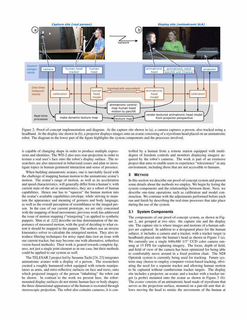
Figure 2: Proof-of-concept implementation and diagram. At the capture site shown in (a), a camera captures a person, also tracked using aheadband. At the display site shown in (b), a projector displays images onto an avatar consisting of a styrofoam head placed on an animatronicrobot. The diagram in the lower part of the figure highlights the system components and the processes involved.
is capable of changing shape in order to produce multiple expres-sions and identities. The WD-2 also uses rear-projection in order totexture a real user’s face onto the robot’s display surface. The re-searchers are also interested in behavioral issues and plan to inves-tigate topics in human-geminoid interaction and sense of presence.
When building animatronic avatars, one is inevitably faced withthe challenge of mapping human motion to the animatronic avatar’smotion. The avatar’s range of motion, as well as its accelerationand speed characteristics, will generally differ from a human’s; withcurrent state-of-the art in animatronics, they are a subset of humancapabilities. Hence one has to “squeeze” the human motion intothe avatar’s available capabilities envelope, while striving to main-tain the appearance and meaning of gestures and body language,as well as the overall perception of resemblance to the imaged per-son. In the case of our current prototype, we are only concernedwith the mapping of head movements; previous work has addressedthe issue of motion mapping (“retargeting”) as applied to syntheticpuppets. Shin et al. [22] describe on-line determination of the im-portance of measured motion, with the goal of deciding to what ex-tent it should be mapped to the puppet. The authors use an inversekinematics solver to calculate the retargeted motion. They also in-troduce filtering techniques for noisy input data (not an issue withour current tracker, but may become one with alternative, tetherlessvision-based methods). Their work is geared towards complete fig-ures, not just a single joint element as in our case, but their methodscould be applied to our system as well.
The TELESAR 2 project led by Susumu Tachi [24, 23] integratesanimatronic avatars with a display of a person. The researcherscreated a roughly humanoid robot equipped with remote manipu-lators as arms, and retro-reflective surfaces on face and torso, ontowhich projected imagery of the person “inhabiting” the robot canbe shown. In contrast to the work we present here, the robot-mounted display surfaces do not mimic human face or body shapes;the three-dimensional appearance of the human is recreated throughstereoscopic projection. The robot also contains cameras; it is con-
trolled by a human from a remote station equipped with multi-degree of freedom controls and monitors displaying imagery ac-quired by the robot’s cameras. The work is part of an extensiveproject that aims to enable users to experience “telexistence” in anyenvironment, including those that are not accessible to humans.
3 METHOD
In this section we describe our proof-of-concept system and presentsome details about the methods we employ. We begin by listing thesystem components and the relationships between them. Next, wedescribe one-time operations such as calibration and model con-struction. We continue with the adjustments performed before eachrun and finish by describing the real-time processes that take placeduring the use of the system.
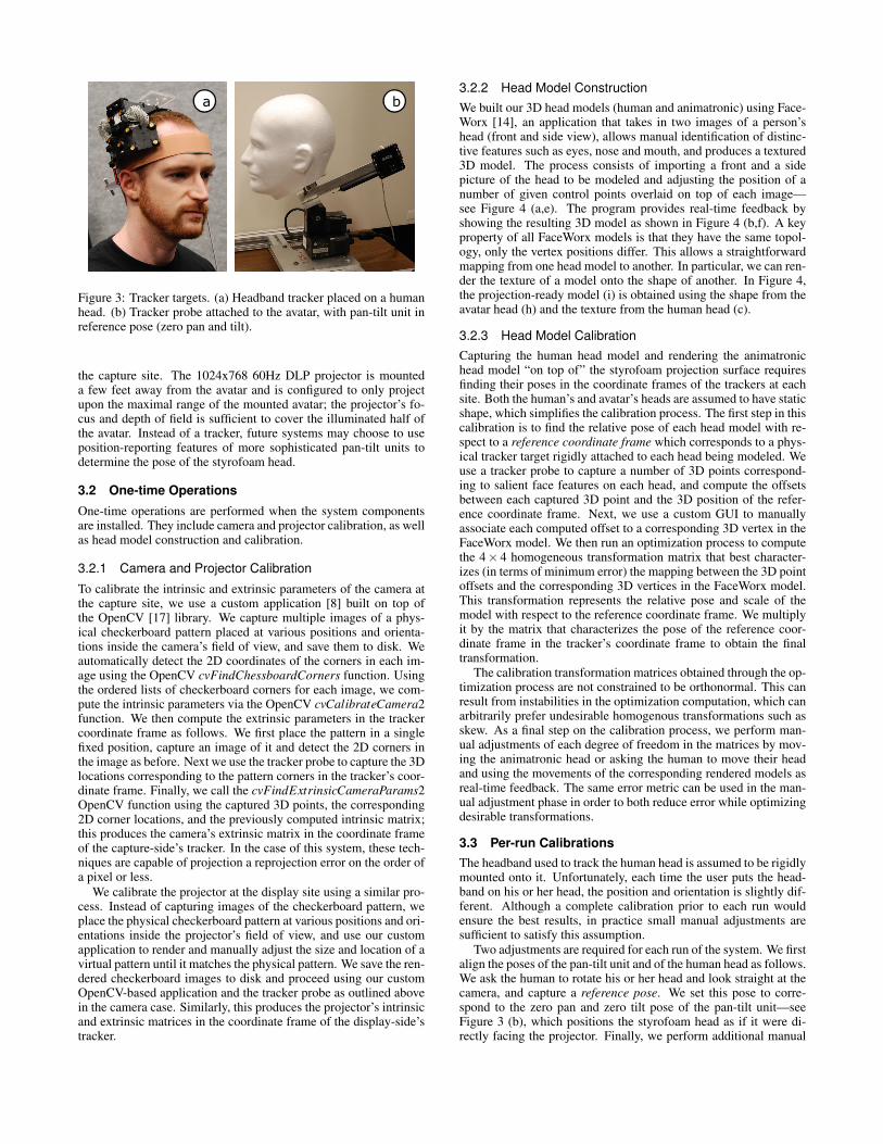
3.1 System ComponentsThe components of our proof-of-concept system, as shown in Fig-ure 2, are grouped at two sites: the capture site and the displaysite. The capture site is where images and motions of a human sub-ject are captured. In addition to a designated place for the humansubject, it includes a camera and a tracker, with a tracker target (aheadband) placed onto the human’s head as shown in Figure 3 (a).We currently use a single 640x480 1/3” CCD color camera run-ning at 15 FPS for capturing imagery. The focus, depth of field,and field of view of the camera has been optimized for being ableto comfortably move around in a fixed position chair. The NDIOptotrak system is currently being used for tracking. Future sys-tems may choose to employ computer-vision-based tracking, obvi-ating the need for a separate tracker and allowing human motionto be captured without cumbersome tracker targets. The displaysite includes a projector, an avatar, and a tracker with a tracker tar-get (a probe) mounted onto the avatar as shown in Figure 3 (b).The avatar consists of an animatronic head made of styrofoam thatserves as the projection surface, mounted on a pan-tilt unit that al-lows moving the head to mimic the movements of the human at
a b
Figure 3: Tracker targets. (a) Headband tracker placed on a humanhead. (b) Tracker probe attached to the avatar, with pan-tilt unit inreference pose (zero pan and tilt).
the capture site. The 1024x768 60Hz DLP projector is mounteda few feet away from the avatar and is configured to only projectupon the maximal range of the mounted avatar; the projector’s fo-cus and depth of field is sufficient to cover the illuminated half ofthe avatar. Instead of a tracker, future systems may choose to useposition-reporting features of more sophisticated pan-tilt units todetermine the pose of the styrofoam head.
3.2 One-time Operations
One-time operations are performed when the system componentsare installed. They include camera and projector calibration, as wellas head model construction and calibration.
3.2.1 Camera and Projector Calibration
To calibrate the intrinsic and extrinsic parameters of the camera atthe capture site, we use a custom application [8] built on top ofthe OpenCV [17] library. We capture multiple images of a phys-ical checkerboard pattern placed at various positions and orienta-tions inside the camera’s field of view, and save them to disk. Weautomatically detect the 2D coordinates of the corners in each im-age using the OpenCV cvFindChessboardCorners function. Usingthe ordered lists of checkerboard corners for each image, we com-pute the intrinsic parameters via the OpenCV cvCalibrateCamera2function. We then compute the extrinsic parameters in the trackercoordinate frame as follows. We first place the pattern in a singlefixed position, capture an image of it and detect the 2D corners inthe image as before. Next we use the tracker probe to capture the 3Dlocations corresponding to the pattern corners in the tracker’s coor-dinate frame. Finally, we call the cvFindExtrinsicCameraParams2OpenCV function using the captured 3D points, the corresponding2D corner locations, and the previously computed intrinsic matrix;this produces the camera’s extrinsic matrix in the coordinate frameof the capture-side’s tracker. In the case of this system, these tech-niques are capable of projection a reprojection error on the order ofa pixel or less.
We calibrate the projector at the display site using a similar pro-cess. Instead of capturing images of the checkerboard pattern, weplace the physical checkerboard pattern at various positions and ori-entations inside the projector’s field of view, and use our customapplication to render and manually adjust the size and location of avirtual pattern until it matches the physical pattern. We save the ren-dered checkerboard images to disk and proceed using our customOpenCV-based application and the tracker probe as outlined abovein the camera case. Similarly, this produces the projector’s intrinsicand extrinsic matrices in the coordinate frame of the display-side’stracker.
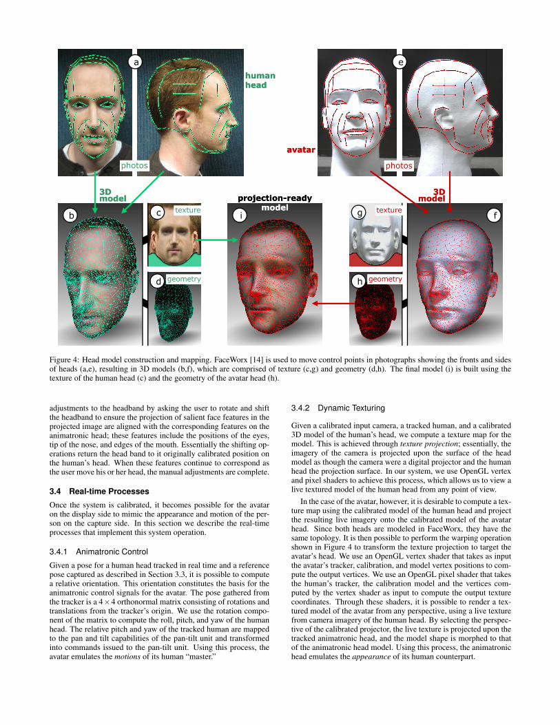
3.2.2 Head Model ConstructionWe built our 3D head models (human and animatronic) using Face-Worx [14], an application that takes in two images of a person’shead (front and side view), allows manual identification of distinc-tive features such as eyes, nose and mouth, and produces a textured3D model. The process consists of importing a front and a sidepicture of the head to be modeled and adjusting the position of anumber of given control points overlaid on top of each image—see Figure 4 (a,e). The program provides real-time feedback byshowing the resulting 3D model as shown in Figure 4 (b,f). A keyproperty of all FaceWorx models is that they have the same topol-ogy, only the vertex positions differ. This allows a straightforwardmapping from one head model to another. In particular, we can ren-der the texture of a model onto the shape of another. In Figure 4,the projection-ready model (i) is obtained using the shape from theavatar head (h) and the texture from the human head (c).
3.2.3 Head Model CalibrationCapturing the human head model and rendering the animatronichead model “on top of” the styrofoam projection surface requiresfinding their poses in the coordinate frames of the trackers at eachsite. Both the human’s and avatar’s heads are assumed to have staticshape, which simplifies the calibration process. The first step in thiscalibration is to find the relative pose of each head model with re-spect to a reference coordinate frame which corresponds to a phys-ical tracker target rigidly attached to each head being modeled. Weuse a tracker probe to capture a number of 3D points correspond-ing to salient face features on each head, and compute the offsetsbetween each captured 3D point and the 3D position of the refer-ence coordinate frame. Next, we use a custom GUI to manuallyassociate each computed offset to a corresponding 3D vertex in theFaceWorx model. We then run an optimization process to computethe 4× 4 homogeneous transformation matrix that best character-izes (in terms of minimum error) the mapping between the 3D pointoffsets and the corresponding 3D vertices in the FaceWorx model.This transformation represents the relative pose and scale of themodel with respect to the reference coordinate frame. We multiplyit by the matrix that characterizes the pose of the reference coor-dinate frame in the tracker’s coordinate frame to obtain the finaltransformation.
The calibration transformation matrices obtained through the op-timization process are not constrained to be orthonormal. This canresult from instabilities in the optimization computation, which canarbitrarily prefer undesirable homogenous transformations such asskew. As a final step on the calibration process, we perform man-ual adjustments of each degree of freedom in the matrices by mov-ing the animatronic head or asking the human to move their headand using the movements of the corresponding rendered models asreal-time feedback. The same error metric can be used in the man-ual adjustment phase in order to both reduce error while optimizingdesirable transformations.
3.3 Per-run CalibrationsThe headband used to track the human head is assumed to be rigidlymounted onto it. Unfortunately, each time the user puts the head-band on his or her head, the position and orientation is slightly dif-ferent. Although a complete calibration prior to each run wouldensure the best results, in practice small manual adjustments aresufficient to satisfy this assumption.
Two adjustments are required for each run of the system. We firstalign the poses of the pan-tilt unit and of the human head as follows.We ask the human to rotate his or her head and look straight at thecamera, and capture a reference pose. We set this pose to corre-spond to the zero pan and zero tilt pose of the pan-tilt unit—seeFigure 3 (b), which positions the styrofoam head as if it were di-rectly facing the projector. Finally, we perform additional manual
a e
c fib
d
g
h
humanheadhumanhead
avataravatar
photosphotos photosphotos
3Dmodel3Dmodel
3Dmodel3D
modelprojection-ready model
projection-ready modeltexturetexture texturetexture
geometrygeometry geometrygeometry
Figure 4: Head model construction and mapping. FaceWorx [14] is used to move control points in photographs showing the fronts and sidesof heads (a,e), resulting in 3D models (b,f), which are comprised of texture (c,g) and geometry (d,h). The final model (i) is built using thetexture of the human head (c) and the geometry of the avatar head (h).
adjustments to the headband by asking the user to rotate and shiftthe headband to ensure the projection of salient face features in theprojected image are aligned with the corresponding features on theanimatronic head; these features include the positions of the eyes,tip of the nose, and edges of the mouth. Essentially the shifting op-erations return the head band to it originally calibrated position onthe human’s head. When these features continue to correspond asthe user move his or her head, the manual adjustments are complete.
3.4 Real-time Processes
Once the system is calibrated, it becomes possible for the avataron the display side to mimic the appearance and motion of the per-son on the capture side. In this section we describe the real-timeprocesses that implement this system operation.
3.4.1 Animatronic Control
Given a pose for a human head tracked in real time and a referencepose captured as described in Section 3.3, it is possible to computea relative orientation. This orientation constitutes the basis for theanimatronic control signals for the avatar. The pose gathered fromthe tracker is a 4×4 orthonormal matrix consisting of rotations andtranslations from the tracker’s origin. We use the rotation compo-nent of the matrix to compute the roll, pitch, and yaw of the humanhead. The relative pitch and yaw of the tracked human are mappedto the pan and tilt capabilities of the pan-tilt unit and transformedinto commands issued to the pan-tilt unit. Using this process, theavatar emulates the motions of its human “master.”
3.4.2 Dynamic Texturing
Given a calibrated input camera, a tracked human, and a calibrated3D model of the human’s head, we compute a texture map for themodel. This is achieved through texture projection; essentially, theimagery of the camera is projected upon the surface of the headmodel as though the camera were a digital projector and the humanhead the projection surface. In our system, we use OpenGL vertexand pixel shaders to achieve this process, which allows us to view alive textured model of the human head from any point of view.
In the case of the avatar, however, it is desirable to compute a tex-ture map using the calibrated model of the human head and projectthe resulting live imagery onto the calibrated model of the avatarhead. Since both heads are modeled in FaceWorx, they have thesame topology. It is then possible to perform the warping operationshown in Figure 4 to transform the texture projection to target theavatar’s head. We use an OpenGL vertex shader that takes as inputthe avatar’s tracker, calibration, and model vertex positions to com-pute the output vertices. We use an OpenGL pixel shader that takesthe human’s tracker, the calibration model and the vertices com-puted by the vertex shader as input to compute the output texturecoordinates. Through these shaders, it is possible to render a tex-tured model of the avatar from any perspective, using a live texturefrom camera imagery of the human head. By selecting the perspec-tive of the calibrated projector, the live texture is projected upon thetracked animatronic head, and the model shape is morphed to thatof the animatronic head model. Using this process, the animatronichead emulates the appearance of its human counterpart.
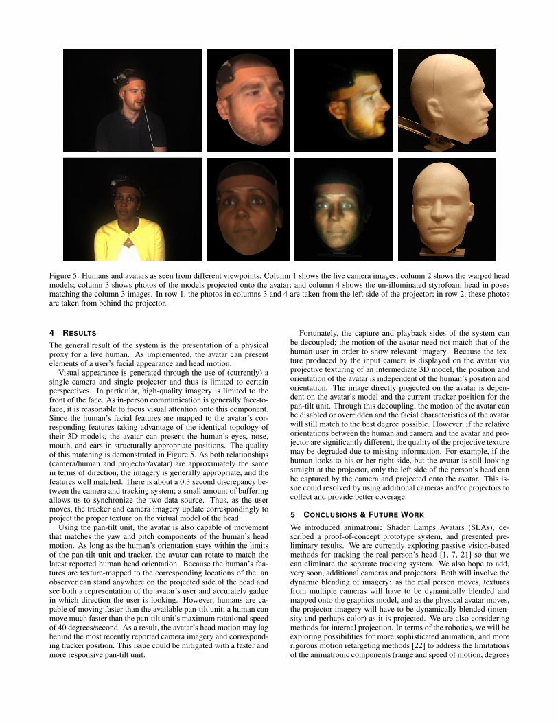
Figure 5: Humans and avatars as seen from different viewpoints. Column 1 shows the live camera images; column 2 shows the warped headmodels; column 3 shows photos of the models projected onto the avatar; and column 4 shows the un-illuminated styrofoam head in posesmatching the column 3 images. In row 1, the photos in columns 3 and 4 are taken from the left side of the projector; in row 2, these photosare taken from behind the projector.
4 RESULTS
The general result of the system is the presentation of a physicalproxy for a live human. As implemented, the avatar can presentelements of a user’s facial appearance and head motion.
Visual appearance is generated through the use of (currently) asingle camera and single projector and thus is limited to certainperspectives. In particular, high-quality imagery is limited to thefront of the face. As in-person communication is generally face-to-face, it is reasonable to focus visual attention onto this component.Since the human’s facial features are mapped to the avatar’s cor-responding features taking advantage of the identical topology oftheir 3D models, the avatar can present the human’s eyes, nose,mouth, and ears in structurally appropriate positions. The qualityof this matching is demonstrated in Figure 5. As both relationships(camera/human and projector/avatar) are approximately the samein terms of direction, the imagery is generally appropriate, and thefeatures well matched. There is about a 0.3 second discrepancy be-tween the camera and tracking system; a small amount of bufferingallows us to synchronize the two data source. Thus, as the usermoves, the tracker and camera imagery update correspondingly toproject the proper texture on the virtual model of the head.
Using the pan-tilt unit, the avatar is also capable of movementthat matches the yaw and pitch components of the human’s headmotion. As long as the human’s orientation stays within the limitsof the pan-tilt unit and tracker, the avatar can rotate to match thelatest reported human head orientation. Because the human’s fea-tures are texture-mapped to the corresponding locations of the, anobserver can stand anywhere on the projected side of the head andsee both a representation of the avatar’s user and accurately gadgein which direction the user is looking. However, humans are ca-pable of moving faster than the available pan-tilt unit; a human canmove much faster than the pan-tilt unit’s maximum rotational speedof 40 degrees/second. As a result, the avatar’s head motion may lagbehind the most recently reported camera imagery and correspond-ing tracker position. This issue could be mitigated with a faster andmore responsive pan-tilt unit.
Fortunately, the capture and playback sides of the system canbe decoupled; the motion of the avatar need not match that of thehuman user in order to show relevant imagery. Because the tex-ture produced by the input camera is displayed on the avatar viaprojective texturing of an intermediate 3D model, the position andorientation of the avatar is independent of the human’s position andorientation. The image directly projected on the avatar is depen-dent on the avatar’s model and the current tracker position for thepan-tilt unit. Through this decoupling, the motion of the avatar canbe disabled or overridden and the facial characteristics of the avatarwill still match to the best degree possible. However, if the relativeorientations between the human and camera and the avatar and pro-jector are significantly different, the quality of the projective texturemay be degraded due to missing information. For example, if thehuman looks to his or her right side, but the avatar is still lookingstraight at the projector, only the left side of the person’s head canbe captured by the camera and projected onto the avatar. This is-sue could resolved by using additional cameras and/or projectors tocollect and provide better coverage.
5 CONCLUSIONS & FUTURE WORK
We introduced animatronic Shader Lamps Avatars (SLAs), de-scribed a proof-of-concept prototype system, and presented pre-liminary results. We are currently exploring passive vision-basedmethods for tracking the real person’s head [1, 7, 21] so that wecan eliminate the separate tracking system. We also hope to add,very soon, additional cameras and projectors. Both will involve thedynamic blending of imagery: as the real person moves, texturesfrom multiple cameras will have to be dynamically blended andmapped onto the graphics model, and as the physical avatar moves,the projector imagery will have to be dynamically blended (inten-sity and perhaps color) as it is projected. We are also consideringmethods for internal projection. In terms of the robotics, we will beexploring possibilities for more sophisticated animation, and morerigorous motion retargeting methods [22] to address the limitationsof the animatronic components (range and speed of motion, degrees
a b
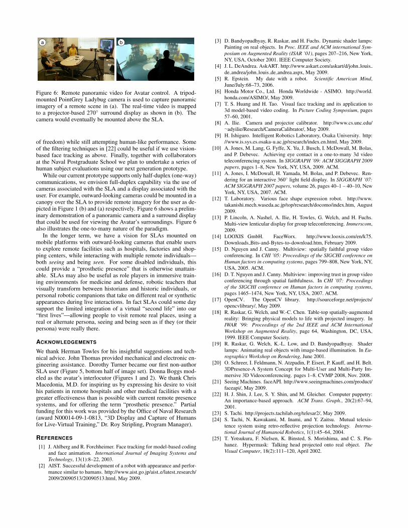
Figure 6: Remote panoramic video for Avatar control. A tripod-mounted PointGrey Ladybug camera is used to capture panoramicimagery of a remote scene in (a). The real-time video is mappedto a projector-based 270◦ surround display as shown in (b). Thecamera would eventually be mounted above the SLA.
of freedom) while still attempting human-like performance. Someof the filtering techniques in [22] could be useful if we use vision-based face tracking as above. Finally, together with collaboratorsat the Naval Postgraduate School we plan to undertake a series ofhuman subject evaluations using our next generation prototype.
While our current prototype supports only half-duplex (one-way)communications, we envision full-duplex capability via the use ofcameras associated with the SLA and a display associated with theuser. For example, outward-looking cameras could be mounted in acanopy over the SLA to provide remote imagery for the user as de-picted in Figure 1 (b) and (a) respectively. Figure 6 shows a prelim-inary demonstration of a panoramic camera and a surround displaythat could be used for viewing the Avatar’s surroundings. Figure 6also illustrates the one-to-many nature of the paradigm.
In the longer term, we have a vision for SLAs mounted onmobile platforms with outward-looking cameras that enable usersto explore remote facilities such as hospitals, factories and shop-ping centers, while interacting with multiple remote individuals—both seeing and being seen. For some disabled individuals, thiscould provide a “prosthetic presence” that is otherwise unattain-able. SLAs may also be useful as role players in immersive train-ing environments for medicine and defense, robotic teachers thatvisually transform between historians and historic individuals, orpersonal robotic companions that take on different real or syntheticappearances during live interactions. In fact SLAs could some daysupport the limited integration of a virtual “second life” into our“first lives”—allowing people to visit remote real places, using areal or alternate persona, seeing and being seen as if they (or theirpersona) were really there.
ACKNOWLEDGEMENTS
We thank Herman Towles for his insightful suggestions and tech-nical advice. John Thomas provided mechanical and electronic en-gineering assistance. Dorothy Turner became our first non-authorSLA user (Figure 5, bottom half of image set). Donna Boggs mod-eled as the avatar’s interlocutor (Figures 1 and 2). We thank ChrisMacedonia, M.D. for inspiring us by expressing his desire to visithis patients in remote hospitals and other medical facilities with agreater effectiveness than is possible with current remote presencesystems, and for offering the term “prosthetic presence.” Partialfunding for this work was provided by the Office of Naval Research(award N00014-09-1-0813, “3D Display and Capture of Humansfor Live-Virtual Training,” Dr. Roy Stripling, Program Manager).
REFERENCES
[1] J. Ahlberg and R. Forchheimer. Face tracking for model-based codingand face animation. International Journal of Imaging Systems andTechnology, 13(1):8–22, 2003.
[2] AIST. Successful development of a robot with appearance and perfor-mance similar to humans. http://www.aist.go.jp/aist e/latest research/2009/20090513/20090513.html, May 2009.
[3] D. Bandyopadhyay, R. Raskar, and H. Fuchs. Dynamic shader lamps:Painting on real objects. In Proc. IEEE and ACM international Sym-posium on Augmented Reality (ISAR ’01), pages 207–216, New York,NY, USA, October 2001. IEEE Computer Society.
[4] J. L. DeAndrea. AskART. http://www.askart.com/askart/d/john louisde andrea/john louis de andrea.aspx, May 2009.
[5] R. Epstein. My date with a robot. Scientific American Mind,June/July:68–73, 2006.
[6] Honda Motor Co., Ltd. Honda Worldwide - ASIMO. http://world.honda.com/ASIMO/, May 2009.
[7] T. S. Huang and H. Tao. Visual face tracking and its application to3d model-based video coding. In Picture Coding Symposium, pages57–60, 2001.
[8] A. Ilie. Camera and projector calibrator. http://www.cs.unc.edu/∼adyilie/Research/CameraCalibrator/, May 2009.
[9] H. Ishiguro. Intelligent Robotics Laboratory, Osaka University. http://www.is.sys.es.osaka-u.ac.jp/research/index.en.html, May 2009.
[10] A. Jones, M. Lang, G. Fyffe, X. Yu, J. Busch, I. McDowall, M. Bolas,and P. Debevec. Achieving eye contact in a one-to-many 3d videoteleconferencing system. In SIGGRAPH ’09: ACM SIGGRAPH 2009papers, pages 1–8, New York, NY, USA, 2009. ACM.
[11] A. Jones, I. McDowall, H. Yamada, M. Bolas, and P. Debevec. Ren-dering for an interactive 360◦ light field display. In SIGGRAPH ’07:ACM SIGGRAPH 2007 papers, volume 26, pages 40–1 – 40–10, NewYork, NY, USA, 2007. ACM.
[12] T. Laboratory. Various face shape expression robot. http://www.takanishi.mech.waseda.ac.jp/top/research/docomo/index.htm, August2009.
[13] P. Lincoln, A. Nashel, A. Ilie, H. Towles, G. Welch, and H. Fuchs.Multi-view lenticular display for group teleconferencing. Immerscom,2009.
[14] LOOXIS GmbH. FaceWorx. http://www.looxis.com/en/k75.Downloads Bits-and-Bytes-to-download.htm, February 2009.
[15] D. Nguyen and J. Canny. Multiview: spatially faithful group videoconferencing. In CHI ’05: Proceedings of the SIGCHI conference onHuman factors in computing systems, pages 799–808, New York, NY,USA, 2005. ACM.
[16] D. T. Nguyen and J. Canny. Multiview: improving trust in group videoconferencing through spatial faithfulness. In CHI ’07: Proceedingsof the SIGCHI conference on Human factors in computing systems,pages 1465–1474, New York, NY, USA, 2007. ACM.
[17] OpenCV. The OpenCV library. http://sourceforge.net/projects/opencvlibrary/, May 2009.
[18] R. Raskar, G. Welch, and W.-C. Chen. Table-top spatially-augmentedreality: Bringing physical models to life with projected imagery. InIWAR ’99: Proceedings of the 2nd IEEE and ACM InternationalWorkshop on Augmented Reality, page 64, Washington, DC, USA,1999. IEEE Computer Society.
[19] R. Raskar, G. Welch, K.-L. Low, and D. Bandyopadhyay. Shaderlamps: Animating real objects with image-based illumination. In Eu-rographics Workshop on Rendering, June 2001.
[20] O. Schreer, I. Feldmann, N. Atzpadin, P. Eisert, P. Kauff, and H. Belt.3DPresence-A System Concept for Multi-User and Multi-Party Im-mersive 3D Videoconferencing. pages 1–8. CVMP 2008, Nov. 2008.
[21] Seeing Machines. faceAPI. http://www.seeingmachines.com/product/faceapi/, May 2009.
[22] H. J. Shin, J. Lee, S. Y. Shin, and M. Gleicher. Computer puppetry:An importance-based approach. ACM Trans. Graph., 20(2):67–94,2001.
[23] S. Tachi. http://projects.tachilab.org/telesar2/, May 2009.[24] S. Tachi, N. Kawakami, M. Inami, and Y. Zaitsu. Mutual telexis-
tence system using retro-reflective projection technology. Interna-tional Journal of Humanoid Robotics, 1(1):45–64, 2004.
[25] T. Yotsukura, F. Nielsen, K. Binsted, S. Morishima, and C. S. Pin-hanez. Hypermask: Talking head projected onto real object. TheVisual Computer, 18(2):111–120, April 2002.