Angular Stable Locking System TGsynthes.vo.llnwd.net/o16/LLNWMB8/US Mobile/Synthes North... ·...
38
Angular Stable Locking System (ASLS). For angular stable locking of intramedullary nails. Technique Guide
Transcript of Angular Stable Locking System TGsynthes.vo.llnwd.net/o16/LLNWMB8/US Mobile/Synthes North... ·...

Angular Stable Locking System(ASLS). For angular stable locking ofintramedullary nails.
Technique Guide

Introduction
Surgical Technique
Product Information
Table of Contents
Image intensifier control
Synthes
Angular Stable Locking System (ASLS) 2
AO Principles 4
Indications 5
Preparation 6
Targeted Locking 8
Freehand Locking 14
Screw Insertion 21
Implant Removal 27
Implants 28
ASLS Compatibility with Existing Nails 29
Instruments 30
Set Lists 33

Angular Stable Locking System (ASLS)
2 Synthes Angular Stable Locking System (ASLS) Technique Guide
Diameter 2: Expands sleeve, providing angular stability
Diameter 1: Provides purchase inreamed near cortex
Angular and axial stability– 80% decrease in fracture site motion
for a period of at least 3 months (12 weeks)1
– Improved fixation in poor quality bone
– Decreased risk of secondary loss ofreduction
Compatibility with existing nails– Compatible with all Synthes
cannulated titanium nails (see page 29 for nail compatibility)
– A combination of standard and ASLSscrews may be used in the same nail
– Intraoperative choice for ASLS
Titanium Angular Stable LockingScrews– Titanium alloy*
– Available lengths – 4.0 mm ASLS screw: 26 mm–80 mm
– 5.0 mm ASLS screw: 30 mm–100 mm
– 6.0 mm ASLS screw: 32 mm–125 mm
– Instruments are color coded to screws
4.0 mm ASLS(brown)
5.0 mm ASLS(light blue)
6.0 mm ASLS(dark purple)
1 Based on in-vitro testing. In-vitro testing may notnecessarily be indicative of clinical performance
* Titanium-6% aluminum-7% niobium alloy

Synthes 3
Diameter 3: Holds unexpanded sleeve for screw insertion, provides purchase in far cortex
2. Ream near cortex
4. Expanded sleeve provides angular stability
3. Insert unexpanded sleeve into nail
1. Drill both cortices
Technique overview
Resorbable Sleeve– 70:30 poly(L /DL-lactide)– Bioresorbable polymer material gradually
resorbs within 18–24 months2
– 4.0 mm, 5.0 mm and 6.0 mm sleeves are used with corresponding ASLS screws
2 Based on in-vivo animal testing. In-vivo animaltesting may not necessarily be indicative of humanclinical performance

AO Principles
In 1958, the AO formulated four basic principles, which havebecome the guidelines for internal fixation.1,2 These principles,as applied to the Angular Stable Locking System (ASLS), are:
Anatomic reductionSynthes IM nails are designed to anatomically fit in themedullary canal, allowing indirect reduction. ASLS reducesthe chance of secondary loss of reduction by providing axialand angular stability.
Stable fixationASLS provides angularly stable fixation between nails andscrews by using resorbable sleeves as dowels in the nail locking holes. The principals of relative stability achieved with intramedullary nailing are still valid with ASLS.
Preservation of blood supplyThe ASLS is used in conjunction with Synthes intramedullarynails which facilitate a percutaneous insertion technique. A percutaneous insertion technique may result in less tissuestripping and resultant vascular trauma than other methods.
Early, active mobilizationThe ASLS is designed to improve angular and axial stability.The stable fixation of fractures may be conducive to optimalrecovery by permitting controlled, early, active rehabilitation.
1. M.E. Müller, M. Allgöwer, R. Schneider, H. Willenegger: Manual of Internal Fixation, 3rd Edition. Berlin; Springer-Verlag. 1991.
2 T.P. Rüedi, R.E. Buckley, C.G. Moran (2007) AO Principles of FractureManagement. 2nd expanded ed. Stuttgart, New York: Thieme. 2002.
4 Synthes Angular Stable Locking System (ASLS) Technique Guide

Indications
The Synthes Angular Stable Locking System (ASLS), whenused with Synthes cannulated titanium intramedullary nails,is intended to aid in the alignment and stabilization of tibial,humeral, femoral and ankle fractures.
Synthes 5

Preparation
The following pages describe techniques for locking withASLS. All illustrations use the Tibial Nail-EX, as an example.
1Preoperative planning
Use the appropriate AO preoperative planner template to estimate nail diameter and length.
2Reduce fracture and insert nail
Reduce the fracture and insert the nail. Use a compatibleSynthes titanium cannulated intramedullary nailing systemaccording to the relevant technique guide.
Note: The ASLS is only compatible with cannulated nails. It is necessary for the sleeve to expand within the cannulationof the intramedullary nail to provide sufficient stability.
6 Synthes Angular Stable Locking System (ASLS) Technique Guide

3Choose appropriate locking screws
For each locking hole, preselect the optimal locking implantto stabilize the fracture. If using an ASLS screw, the diameterof the ASLS screw and instruments will match the diameterof the standard screw/bolt for the particular nail.
Note: A combination of standard locking screws/bolts andASLS screws can be used in the same nail.
Caution: Do not exchange a standard locking screw/bolt foran ASLS screw or vice versa as this may reduce screw-to-boneinterface stability.
Synthes 7

Targeted Locking
1Attach aiming arm and insert trocar combination
Instruments
03.010.063† 12.0 mm/8.0 mm Protection Sleeve, 188 mm (for Expert nails)
03.025.040* 11.0 mm/8.0 mm Protection Sleeve, 188 mm, for ASLS
4.0 mm
03.010.064† 8.0 mm/3.2 mm Drill Sleeve
03.010.069† 3.2 mm Trocar
5.0 mm
03.010.065† 8.0 mm/4.2 mm Drill Sleeve
03.010.070† 4.2 mm Trocar
6.0 mm
03.010.066† 8.0 mm/5.0 mm Drill Sleeve
03.010.071† 5.0 mm Trocar
Once the nail is inserted, attach the aiming arm to the insertion handle. Confirm that the nail is tightly connected to the insertion handle.
Insert the appropriate three-part trocar combination (protectionsleeve, drill sleeve and trocar) through the desired hole in the aiming arm. Make a skin incision and ensure that the dissection of the fascia is in line with the path of the protectionsleeve. Advance the three-part trocar combination to thebone. Remove the trocar.
Note: Ensure that the drill sleeve is pressed firmly to the near cortex.
8 Synthes Angular Stable Locking System (ASLS) Technique Guide
† Found in the Expert nail instrument sets* Also available

2Drill through both cortices
Instruments
4.0 mm
03.025.104 2.9 mm/3.2 mm Three-Fluted Drill Bit, quick coupling, 331 mm
5.0 mm
03.025.105 3.9 mm/4.2 mm Three-Fluted Drill Bit, quick coupling, 331 mm
6.0 mm
03.025.106 4.9 mm/5.0 mm Three-Fluted Drill Bit, quick coupling, 331 mm
Using the appropriate drill bit, drill through both cortices until the tip of the drill bit penetrates the far cortex.
If necessary, use image intensification to control the positionof the drill bit.
Note: Follow all recommended techniques for screw/bolt insertion for the relevant nail system. When inserting a screwmonocortically, stop drilling immediately after penetratingthe near cortex.
Synthes 9

3Determine ASLS screw length
Read the measurement from the calibrated drill bit at the backof the drill sleeve. Select the ASLS screw length accordingly.Remove the drill bit and drill sleeve.
Note: Follow all recommended techniques for screw/boltmeasurement for the relevant nail system.
10 Synthes Angular Stable Locking System (ASLS) Technique Guide
Targeted Locking continued
Alternative technique
Instrument
03.025.052 Depth Gauge, for ASLS screws
Remove the drill bit and the drill sleeve. Disassemble thedepth gauge, separating the outer sleeve from the measuringdevice with hook. Insert the measuring device with hook intothe protection sleeve.
Read the measurement from the back of the protectionsleeve and select the ASLS screw length accordingly.
Note: Ensure that the hook grasps the far cortex and thatthe protection sleeve is pressed firmly to the bone.
Synthes 11

12 Synthes Angular Stable Locking System (ASLS) Technique Guide
Targeted Locking continued
4Ream near cortex
Instruments
4.0 mm
03.025.030 2.9 mm/5.0 mm Hand Reamer
5.0 mm
03.025.031 3.9 mm/6.0 mm Hand Reamer
6.0 mm
03.025.032 4.9 mm/7.0 mm Hand Reamer
Align the hand reamer with the locking hole axis. Ream thenear cortex and clear the passage down to the nail. Removethe hand reamer.
If necessary, use image intensification to control the positionof the hand reamer.
Note: To correctly insert the ASLS sleeve, ensure:– the near cortex is completely reamed;– the passage from the near cortex to the nail’s locking hole
is cleared;– the drilled/ reamed hole aligns with the nail’s locking hole.

Alternative technique
Instruments
4.0 mm
03.025.134 2.9 mm/5.0 mm Drill-Reamer, quick coupling, 268 mm
5.0 mm
03.025.135 3.9 mm/6.0 mm Drill-Reamer, quick coupling, 288 mm
6.0 mm
03.025.136 4.9 mm/7.0 mm Drill-Reamer, quick coupling, 288 mm
Use a power driven drill-reamer to open the near cortex.Align the drill-reamer with the locking hole axis and reamthe near cortex. Once the large diameter of the drill-reamerpasses through the near cortex, stop reaming immediately.Remove the drill-reamer.
If necessary, clear the passage down to the nail with thehand reamer.
If necessary, use image intensification to control the positionof the drill-reamer.
Caution: Ensure that the drill-reamer does not damage the nail.
Insert screws in targeted locking holes (see Screw Insertion,page 21), before continuing with freehand locking.
Synthes 13

Freehand Locking
2Make incision
Using image intensification, place a long K-wire or alternativelong instrument on the skin over the center of the hole tomark the incision point.
Make a skin incision with a scalpel blade at this location.
Note: Check the reduction, correct alignment of the fragments,and limb length before locking.
14 Synthes Angular Stable Locking System (ASLS) Technique Guide
1Align image
The techniques for distal locking apply. Align the image intensifier with the desired locking hole until a perfect circleis visible in the center of the screen.
Note: Ensure that the image displayed on the image intensifier mirrors the actual image in all axes.

3Drill through both cortices
Instruments
511.30* Radiolucent Drive
4.0 mm
03.025.124* 2.9 mm/3.2 mm Three-Fluted Drill Bit, quick coupling, 145 mm, for Radiolucent Drive
5.0 mm
03.025.125* 3.9 mm/4.2 mm Three-Fluted Drill Bit, quick coupling, 145 mm, for Radiolucent Drive
6.0 mm
03.025.126* 4.9 mm/5.0 mm Three-Fluted Drill Bit, quick coupling, 145 mm, for Radiolucent Drive
Attach the appropriate drill bit to the radiolucent drive. Usingimage intensification, insert the tip of the drill bit through theincision and to the bone.
Incline the drive to center the tip of the drill bit over the lockinghole. The drill bit should nearly fill the circle of the lockinghole. Hold the drill bit in this position and drill through bothcortices. Stop drilling immediately after the tip of the drillpenetrates the far cortex. Remove the drill bit.
Note: Follow all recommended techniques for screw/bolt insertion for the relevant nail system. When inserting lockingscrews monocortically, stop drilling immediately after pene-trating the near cortex.
Synthes 15
* Also available

3Drill through both cortices continued
Alternative technique
Instruments
4.0 mm
03.025.082 2.9 mm/3.2 mm Three-Fluted Drill Bit, quick coupling, 150 mm
5.0 mm
03.025.083 3.9 mm/4.2 mm Three-Fluted Drill Bit, quick coupling, 150 mm
6.0 mm
03.025.084 4.9 mm/5.0 mm Three-Fluted Drill Bit, quick coupling, 150 mm
Standard freehand locking technique can be performedwithout the radiolucent drive, using the appropriate drill bit.
16 Synthes Angular Stable Locking System (ASLS) Technique Guide
Freehand Locking continued

4Determine ASLS screw length
Instrument
03.025.052 Depth Gauge, for ASLS screws
Insert the depth gauge into the drilled hole. Read the measure-ment from the outer sleeve of the depth gauge and selectthe ASLS screw length accordingly.
Note: Follow all recommended techniques for screw/boltmeasurement for the relevant nail system. Ensure that thehook grasps the far cortex and that the protection sleeve ispressed firmly to the bone.
Synthes 17

4Determine ASLS screw length continued
Alternative technique for radiolucent drill bits
Instrument
03.010.106† Direct Measuring Device, for Locking Screws to 100 mm
Stop drilling immediately after the tip of the drill penetratesthe far cortex.
Disassemble the drill bit from the radiolucent drive.
Place the direct measuring device onto the drill bit. Read thegraduation of the measuring device at the end of the drillbit. This corresponds to the appropriate screw length.
18 Synthes Angular Stable Locking System (ASLS) Technique Guide
Freehand Locking continued
† Found in the Expert nail instrument sets

5Ream near cortex
Instruments
4.0 mm
03.025.030 2.9 mm/5.0 mm Hand Reamer
5.0 mm
03.025.031 3.9 mm/6.0 mm Hand Reamer
6.0 mm
03.025.032 4.9 mm/7.0 mm Hand Reamer
Align the hand reamer with the locking hole axis. Ream thenear cortex and clear the passage down to the nail. Removethe hand reamer.
If necessary, use image intensification to control the positionof the hand reamer.
Note: To correctly insert the ASLS sleeve, ensure:– the near cortex is completely reamed;– the passage from the near cortex to the nail’s locking
hole is cleared;– the drilled/ reamed hole aligns with the nail’s locking hole.
Synthes 19

5Ream near cortex continued
Alternative technique
Instruments
4.0 mm
03.025.027 2.9 mm/5.0 mm Drill-Reamer, quick coupling, 145 mm
5.0 mm
03.025.028 3.9 mm/6.0 mm Drill-Reamer, quick coupling, 145 mm
6.0 mm
03.025.029 4.9 mm/7.0 mm Drill-Reamer, quick coupling, 145 mm
Use the appropriate drill-reamer to open the near cortex.Align the drill-reamer with the locking hole axis and reamthe near cortex. Once the large diameter of the drill-reamerpasses through the near cortex, stop reaming immediately.Remove the drill-reamer.
If necessary, clear the passage down to the nail with thehand reamer.
If necessary, use image intensification to control the positionof the drill-reamer.
Caution: Ensure that the drill-reamer does not damage the nail.
20 Synthes Angular Stable Locking System (ASLS) Technique Guide
Freehand Locking continued

Screw Insertion
1Position sleeve
Select the appropriate resorbable sleeve.
Position the sleeve so that the sleeve lip is facing thescrewhead. Thread the ASLS sleeve onto the ASLS screw.
Note: The sleeve is positioned correctly when gold is visibleon either side of the sleeve and the screw tip protrudes 1 mm–2 mm beyond the sleeve.
Caution:Do not use ASLS screws without sleeves.
When attaching the sleeve, stop threading the sleeve onceresistance increases. Resistance occurs when the sleeve expands as it moves onto the larger diameter of the screw.An expanded sleeve will prevent screw/sleeve insertion into a locking hole.
Synthes 21
1–2 mm
Sleeve lip

1Position sleeve continued
Alternative technique
Instruments
4.0 mm/5.0 mm
03.025.067 Sleeve Positioner
6.0 mm
03.025.066 Sleeve Positioner
Place the sleeve into the appropriate side of the sleeve positioner. Rotate the screw into the sleeve until the sleeve is pushed out of the sleeve positioner.
22 Synthes Angular Stable Locking System (ASLS) Technique Guide
Screw Insertion continued

2Insert screw/sleeve assembly into locking hole
Instruments
03.010.063† 12.0 mm/8.0 mm, Protection Sleeve, 188 mm (for Expert nails)
03.010.107† StarDrive Screwdriver, T25, self-retaining
03.025.040* 11.0 mm/8.0 mm, Protection Sleeve, 188 mm,for ASLS
4.0 mm
03.010.064† 8.0 mm/3.2 mm Drill Sleeve
03.010.069† 3.2 mm Trocar
5.0 mm
03.010.065† 8.0 mm/4.2 mm Drill Sleeve
03.010.070† 4.2 mm Trocar
6.0 mm
03.010.066† 8.0 mm/5.0 mm Drill Sleeve
03.010.071† 5.0 mm Trocar
Assemble the appropriate protection sleeve, drill sleeve andtrocar and advance the assembly to the bone. Remove thedrill sleeve and trocar. Attach the ASLS screw/sleeve assemblyto the screwdriver.
Synthes 23
† Found in the Expert nail instrument sets* Also available

2Insert screw/sleeve assembly into locking hole continued
Push the ASLS screw/sleeve assembly through the protectionsleeve and near cortex, and into the nail’s locking hole. Ifnecessary, lightly tap the screwdriver to advance the screw/sleeve into the locking hole.
Caution: Do not rotate the screwdriver until the sleeve isseated in the locking hole.
Note: If the screw/sleeve assembly cannot be pushed to thenail stop, use the appropriate reamer to completely open thenear cortex (see earlier step “Ream near cortex”).
Optional technique
Instrument
399.505 Synthetic Hammer
If necessary, lightly hammer to advance the screw/sleeve assembly into the nail’s locking hole.
24 Synthes Angular Stable Locking System (ASLS) Technique Guide
Screw Insertion continued

3Screw into far cortex
Push the screwdriver to get the screw started. Rotate thescrewdriver to advance the screw until the screw threads engage the far cortex.
Notes: The larger diameter core expands the sleeve in the nail, providing angular stability.
In the final screw position, the largest diameter screw threadswill engage the near cortex and the screw tip will protrudebeyond the far cortex.
Synthes 25

3Screw into far cortex continued
Note: To prevent over-insertion of the ASLS screw, use a protection sleeve during screw insertion. Ensure that the protection sleeve is pressed to the bone. Advance the screwuntil the engraved line on the screwdriver shaft meets theedge of the protection sleeve.
After insertion of all screws, use image intensification to ensure that reduction is maintained, that the screwheadscontact the bone, and that the screws are not over-inserted.
26 Synthes Angular Stable Locking System (ASLS) Technique Guide
Screw Insertion continued
† Found in the Expert nail instrument sets
4Intraoperative screw exchange
Instruments
03.010.107† StarDrive Screwdriver, T25, self-retaining
03.010.112† Holding Sleeve, with Locking Device
Using standard technique, remove the ASLS screw with thescrewdriver and, if necessary, by pulling with the holding sleeve.
Note: Since the sleeve remains in the nail, it does not needto be removed and exchanged.
Insert a new ASLS screw.
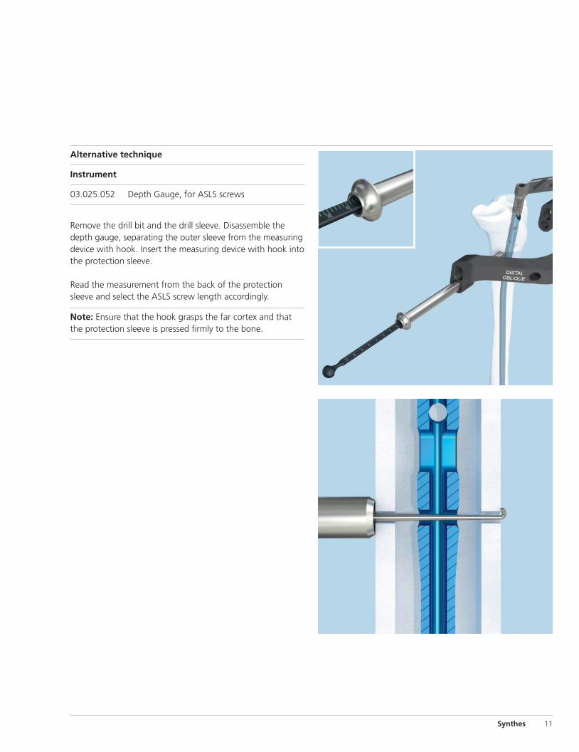
Implant Removal
1Remove screws
Instruments
03.010.107† StarDrive Screwdriver, T25, self-retaining
03.010.112† Holding Sleeve, with Locking Device
Using standard technique, remove ASLS screws with thescrewdriver and, if necessary, the holding sleeve.
2Remove nail
Remove the nail using standard technique for the relevantnail system.
Note: The sleeves remain in the nail if not fully resorbed andcan be removed with the nail during nail removal.
Synthes 27
† Found in the Expert nail instrument sets

Resorbable Sleeves for Angular Stable Locking Screws,sterile*
– 70:30 poly(L /DL-lactide)
– Bioresorbable polymer material gradually resorbs within 18–24 months1
– Inner thread for secure fit to ASLS screw
– Expands in nail’s locking hole to provide angular stability
– 4.0 mm, 5.0 mm and 6.0 mm sleeves used with corresponding ASLS screws
– Sterile packaged (2 per package)
Implants
28 Synthes Angular Stable Locking System (ASLS) Technique Guide
Titanium Angular Stable Locking Screws, with T25 StarDrive recess, for intramedullary nails, sterile*
– Titanium alloy**
– Available lengths– 4.0 mm ASLS screw: 26 mm–80 mm– 5.0 mm ASLS screw: 30 mm–100 mm– 6.0 mm ASLS screw: 32 mm–125 mm
– Fully threaded shaft with 3 diameters– D1: Provides purchase in reamed near cortex– D2: Expands sleeve, providing angular stability– D3: Holds unexpanded sleeve for screw insertion,
provides purchase in far cortex
– T25 StarDrive recess
– Sterile packaged
D1
D2
D3
1 Based on in-vivo animal testing. In-vivo animal testing maynot necessarily be indicative of human clinical performance
* Also available** Titanium-6% aluminum-7% niobium alloy

Synthes 29
ASLS Compatibility with Existing Nails
The Angular Stable Locking System is compatible with all Synthes titanium cannulated nailing systems.
Angular Stable Locking Systems
Nail 4.0 mm 5.0 mm 6.0 mmNailing System Diameters (mm) (brown) (light blue) (dark purple)
Humerus Titanium Cannulated Humeral Nailand Proximal Humeral Nail-EX
7, 9, 11 •
Femur Titanium Trochanteric Fixation Nail 10, 11, 12, 14 •
Titanium Cannulated Lateral Entry 9–13 •Femoral Nail-EX and Lateral EntryFemoral Recon Nail-EX 14–16 •
Titanium Cannulated Retrograde/ 9–13 •Antegrade Femoral Nail-EX 14, 15 •
Titanium Femoral Nail (cannulated) 10–15 •
Titanium Distal Femoral Nail(cannulated)
10–13 • •
Titanium Cannulated AdolescentLateral Entry Femoral Nail-EX
8.2, 9, 10 •
Tibia Titanium Cannulated Tibial Nail-EX 8, 9 •and Tibial Nail-EX with Proximal Bend 10–13 •
Titanium Tibial Nail (cannulated) 10–13 •
Ankle Titanium Cannulated Hindfoot • •
Arthrodesis Nail-EX10, 12, 13

Instruments
03.025.040* 11.0 mm/8.0 mm, Protection Sleeve, 188 mm, for ASLS– to be used with non-Expert nails
03.010.107† StarDrive Screwdriver, T25
03.010.112† Holding Sleeve, with Locking Device
03.025.052 Depth Gauge, for ASLS screws
03.025.067 Sleeve Positioner, for 4.0 mm and 5.0 mm ASLS sleeves
03.025.066 Sleeve Positioner, for 6.0 mm ASLS sleeves
399.505 Synthetic Hammer (100 g)
30 Synthes Angular Stable Locking System (ASLS) Technique Guide
General instruments
03.010.063† 12.0 mm/8.0 mm, Protection Sleeve, 188 mm – to be used with Expert nails
† Found in the Expert nail instrument sets* Also available

Synthes 31
Instruments for targeted locking
03.010.064† 8.0 mm/3.2 mm Drill Sleeve03.010.065† 8.0 mm/4.2 mm Drill Sleeve03.010.066† 8.0 mm/5.0 mm Drill Sleeve
03.010.069† 3.2 mm Trocar03.010.070† 4.2 mm Trocar03.010.071† 5.0 mm Trocar
03.025.104 2.9 mm/3.2 mm Three-Fluted Drill Bit, quick coupling, 331 mm, for 4.0 mm ASLS screws
03.025.105 3.9 mm/4.2 mm Three-Fluted Drill Bit, quick coupling, 331 mm, for 5.0 mm ASLS screws
03.025.106 4.9 mm/5.0 mm Three-Fluted Drill Bit, quick coupling, 331 mm, for 6.0 mm ASLS screws
03.025.134 2.9 mm/5.0 mm Drill-Reamer, quick coupling,268 mm, for 4.0 mm ASLS screws
03.025.135 3.9 mm/6.0 mm Drill-Reamer, quick coupling,288 mm, for 5.0 mm ASLS screws
03.025.136 4.9 mm/7.0 mm Drill-Reamer, quick coupling,288 mm, for 6.0 mm ASLS screws
03.025.030 2.9 mm/5.0 mm Hand Reamer, for 4.0 mm ASLS screws
03.025.031 3.9 mm/6.0 mm Hand Reamer, for 5.0 mm ASLS screws
03.025.032 4.9 mm/7.0 mm Hand Reamer, for 6.0 mm ASLS screws
† Found in the Expert nail instrument sets

03.025.030 2.9 mm/5.0 mm Hand Reamer, for 4.0 mm ASLS screws
03.025.031 3.9 mm/6.0 mm Hand Reamer, for 5.0 mm ASLS screws
03.025.032 4.9 mm/7.0 mm Hand Reamer, for 6.0 mm ASLS screws
Instruments continued
03.025.082 2.9 mm/3.2 mm Three-Fluted Drill Bit, quick coupling, 150 mm, for 4.0 mm ASLS screws
03.025.083 3.9 mm/4.2 mm Three-Fluted Drill Bit, quick coupling, 150 mm, for 5.0 mm ASLS screws
03.025.084 4.9 mm/5.0 mm Three-Fluted Drill Bit, quick coupling, 150 mm, for 6.0 mm ASLS screws
Instruments for freehand locking
03.025.027 2.9 mm/5.0 mm Drill-Reamer, quick coupling,145 mm, for 4.0 mm ASLS screws
03.025.028 3.9 mm/6.0 mm Drill-Reamer, quick coupling,145 mm, for 5.0 mm ASLS screws
03.025.029 4.9 mm/7.0 mm Drill-Reamer, quick coupling,145 mm, for 6.0 mm ASLS screws
32 Synthes Angular Stable Locking System (ASLS) Technique Guide
03.025.124* 2.9 mm/3.2 mm Three-Fluted Drill Bit, quick coupling, 145 mm, for 4.0 mm ASLS screws, for Radiolucent Drive
03.025.125* 3.9 mm/4.2 mm Three-Fluted Drill Bit, quick coupling, 145 mm, for 5.0 mm ASLS screws, for Radiolucent Drive
03.025.126* 4.9 mm/5.0 mm Three-Fluted Drill Bit, quick coupling, 145 mm, for 6.0 mm ASLS screws, for Radiolucent Drive
* Also available

Synthes 33
Drill-Reamers, quick coupling, 2 ea.03.025.134 2.9 mm/5.0 mm, 268 mm, for 4.0 mm
Angular Stable Locking Screws
03.025.135 3.9 mm/6.0 mm, 288 mm, for 5.0 mm Angular Stable Locking Screws
03.025.136 4.9 mm/7.0 mm, 288 mm, for 6.0 mm Angular Stable Locking Screws
Angular Stable Locking System Instrument Set (01.025.002)
60.025.002 Graphic Case for Angular Stable Locking System, for Cannulated Titanium Intramedullary Nails
Instruments399.505 Synthetic Hammer
Drill-Reamers, quick coupling, 145 mm, 2 ea.03.025.027 2.9 mm/5.0 mm, for 4.0 mm
Angular Stable Locking Screws
03.025.028 3.9 mm/6.0 mm, for 5.0 mm Angular Stable Locking Screws
03.025.029 4.9 mm/7.0 mm, for 6.0 mm Angular Stable Locking Screws
Hand Reamers 03.025.030 2.9 mm/5.0 mm, for 4.0 mm
Angular Stable Locking Screws
03.025.031 3.9 mm/6.0 mm, for 5.0 mm Angular Stable Locking Screws
03.025.032 4.9 mm/7.0 mm, for 6.0 mm Angular Stable Locking Screws
03.025.052 Depth Gauge, for Angular Stable Locking System
03.025.066 Sleeve Positioner, for 6.0 mm Angular Stable Locking System Sleeves
03.025.067 Sleeve Positioner, for 4.0 mm and 5.0 mm Angular Stable Locking System Sleeves
Three-Fluted Drill Bits, quick coupling, needle point, 150 mm, 2 ea.
03.025.082 2.9 mm/3.2 mm, for 4.0 mm Angular Stable Locking Screws
03.025.083 3.9 mm/4.2 mm, for 5.0 mm Angular Stable Locking Screws
03.025.084 4.9 mm/5.0 mm, for 6.0 mm Angular Stable Locking Screws
Three-Fluted Drill Bits, quick coupling, needlepoint, 331 mm, 100 mm calibration, 2 ea.
03.025.104 2.9 mm/3.2 mm, for 4.0 mm Angular Stable Locking Screws
03.025.105 3.9 mm/4.2 mm, for 5.0 mm Angular Stable Locking Screws
03.025.106 4.9 mm/5.0 mm, for 6.0 mm Angular Stable Locking Screws
Note: For additional information, please refer to package insert.For detailed cleaning and sterilization instructions, please refer tohttp://us.synthes.com/Medical+Community/Cleaning+and+Sterilization.htmor to the below listed inserts, which will be included in the shipping container:–Processing Synthes Reusable Medical Devices—Instruments, Instrument Traysand Graphic Cases—DJ1305
–Processing Non-sterile Synthes Implants—DJ1304

34 Synthes Angular Stable Locking System (ASLS) Technique Guide
01.025.008 4.0 mm Angular Stable Locking SystemScrew Set
4.0 mm Titanium Angular Stable Locking Screws, with T25StarDrive recess, for intramedullary nails, sterile, 2 ea.
Length Length(mm) (mm)
04.025.416S 26 04.025.444S 5404.025.418S 28 04.025.446S 5604.025.420S 30 04.025.448S 5804.025.422S 32 04.025.450S 6004.025.424S 34 04.025.452S 6204.025.426S 36 04.025.454S 6404.025.428S 38 04.025.456S 6604.025.430S 40 04.025.458S 6804.025.432S 42 04.025.460S 7004.025.434S 44 04.025.462S 7204.025.436S 46 04.025.464S 7404.025.438S 48 04.025.466S 7604.025.440S 50 04.025.468S 7804.025.442S 52 04.025.470S 80
01.025.009 5.0 mm Angular Stable Locking SystemScrew Set
5.0 mm Titanium Angular Stable Locking Screws, with T25StarDrive recess, for intramedullary nails, sterile, 2 ea.
Length Length(mm) (mm)
04.025.520S 30 04.025.550S 6004.025.522S 32 04.025.552S 6204.025.524S 34 04.025.554S 6404.025.526S 36 04.025.556S 6604.025.528S 38 04.025.558S 6804.025.530S 40 04.025.560S 7004.025.532S 42 04.025.562S 7204.025.534S 44 04.025.564S 7404.025.536S 46 04.025.566S 7604.025.538S 48 04.025.568S 7804.025.540S 50 04.025.570S 8004.025.542S 52 04.025.575S 8504.025.544S 54 04.025.580S 9004.025.546S 56 04.025.585S 9504.025.548S 58 04.025.590S 100
Implant Sets
ASLS Screws
Synthes 35
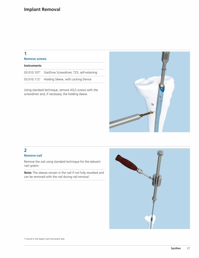
01.025.010 6.0 mm Angular Stable Locking SystemScrew Set
6.0 mm Titanium Angular Stable Locking Screws, with T25StarDrive recess, for intramedullary nails, sterile, 2 ea.
Length Length(mm) (mm)
04.025.622S 32 04.025.656S 6604.025.624S 34 04.025.658S 6804.025.626S 36 04.025.660S 7004.025.628S 38 04.025.662S 7204.025.630S 40 04.025.664S 7404.025.632S 42 04.025.666S 7604.025.634S 44 04.025.668S 7804.025.636S 46 04.025.670S 8004.025.638S 48 04.025.675S 8504.025.640S 50 04.025.680S 9004.025.642S 52 04.025.685S 9504.025.644S 54 04.025.690S 10004.025.646S 56 04.025.695S 10504.025.648S 58 04.025.700S 11004.025.650S 60 04.025.705S 11504.025.652S 62 04.025.710S 12004.025.654S 64 04.025.715S 125
Alternative Set Configurations
01.025.001 Angular Stable Locking System Screw Set Consists of:4.0 mm ASLS Screw Set (01.025.008) and 5.0 mm ASLS Screw Set (01.025.009)
ASLS Sleeves*
Resorbable Sleeve for Angular Stable Locking Screws, sterile, 2/pkg.
08.025.032S for 4.0 mm ASLS Screws08.025.044S for 5.0 mm ASLS Screws08.025.057S for 6.0 mm ASLS Screws
* Must be ordered separately.

36 Synthes Angular Stable Locking System Technique Guide
InstrumentsDrill-Reamers, quick coupling, 145 mm,for Radiolucent Drive
03.025.037 2.9 mm/5.0 mm, for 4.0 mm Angular Stable Locking Screws
03.025.038 3.9 mm/6.0 mm, for 5.0 mm Angular Stable Locking Screws
03.025.039 4.9 mm/7.0 mm, for 6.0 mm Angular Stable Locking Screws
03.025.040 11.0 mm/8.0 mm Protection Sleeve, 188 mm,for Angular Stable Locking System
Three-Fluted Drill Bits, quick coupling, needle point, 145 mm, for Radiolucent Drive
03.025.124 2.9 mm / 3.2 mm, for 4.0 mm Angular Stable Locking Screws
03.025.125 3.9 mm/4.2 mm, for 5.0 mm Angular Stable Locking Screws
03.025.126 4.9 mm/5.0 mm, for 6.0 mm Angular Stable Locking Screws
Expert Nail Instruments†
03.010.063 12.0 mm/8.0 mm Protection Sleeve, 188 mm
Drill Sleeves03.010.064 8.0 mm/3.2 mm, 200 mm
03.010.065 8.0 mm/4.2 mm, 200 mm
03.010.066 8.0 mm/5.0 mm, 200 mm
Trocars03.010.069 3.2 mm, 210 mm
03.010.070 4.2 mm, 210 mm
03.010.071 5.0 mm, 210 mm
03.010.106 Direct Measuring Device, for Locking Screws to 100 mm, for IM Nails
03.010.107 StarDrive Screwdriver, T25, self-retaining
03.010.112 Holding Sleeve, with Locking Device
03.010.150 Star /HexDrive Screwdriver, T25, 3.5 mm hex, self-retaining
Power Equipment105.955 Small Battery Drive Set
150.119 Battery Power Line Set
511.30 Radiolucent Drive
530.605 Battery Reamer /Drill
530.620 Battery, for Battery Power Line
530.680 Battery Casing, for Battery Power Line
530.741 Adaptor for Radiolucent Drive, for Battery Power Line
530.750 Quick Coupling for Drill Bits, for Battery Power Line
532.010 Small Battery Drive
532.013 Quick Coupling for Drill Bits
532.031 Adaptor for Radiolucent Drive
532.032 Small Battery Drive Battery Casing, for 14.4 V Battery
532.033 Small Battery Drive 14.4 V Battery
Also Available
† Found in the Expert nail instrument sets

Synthes (USA)1302 Wrights Lane EastWest Chester, PA 19380Telephone: (610) 719-5000To order: (800) 523-0322Fax: (610) 251-9056
Synthes (Canada) Ltd.2566 Meadowpine BoulevardMississauga, Ontario L5N 6P9Telephone: (905) 567-0440To order: (800) 668-1119Fax: (905) 567-3185
© 2009 Synthes, Inc. or its affiliates. All rights reserved. Synthes is a trademark of Synthes, Inc. or its affiliates. Printed in U.S.A. 5/10 J8691-B
www.synthes.com