Angular Stable Locking System (ASLS). For angular …synthes.vo.llnwd.net/o16/LLNWMB8/INT...
44
Angular Stable Locking System (ASLS). For angular stable locking of intra-medullary nails. Surgical Technique This publication is not intended for distribution in the USA. Instruments and implants approved by the AO Foundation.
Transcript of Angular Stable Locking System (ASLS). For angular …synthes.vo.llnwd.net/o16/LLNWMB8/INT...

Angular Stable Locking System (ASLS). For angular stable locking of intra-medullary nails.
Surgical Technique
This publication is not intended for distribution in the USA.
Instruments and implants approved by the AO Foundation.

Image intensifier control
This description alone does not provide sufficient background for direct use of DePuy Synthes products. Instruction by a surgeon experienced in handling these products is highly recommended.
Processing, Reprocessing, Care and MaintenanceFor general guidelines, function control and dismantling of multi-part instruments, as well as processing guidelines for implants, please contact your local sales representative or refer to:http://emea.depuysynthes.com/hcp/reprocessing-care-maintenanceFor general information about reprocessing, care and maintenance of Synthes reusable devices, instrument trays and cases, as well as processing of Synthes non-sterile implants, please consult the Important Information leaflet (SE_023827) or refer to: http://emea.depuysynthes.com/hcp/reprocessing-care-maintenance

Angular Stable Locking System (ASLS) Surgical Technique DePuy Synthes 1
Introduction
Surgical Technique
Product Information
Bibliography 39
MRI Information 40
Angular Stable Locking System (ASLS) 2
AO Principles 4
Indications and Contraindications 5
Preparation 6
Targeted Locking 8
Freehand Locking 14
Screw Insertion 21
Implant Removal 27
Implants 28
ASLS Compatibility with Existing Nails 30
Instruments 32
Vario Case 35
Power Tools 36
Sets 37
Table of Contents
2 DePuy Synthes Angular Stable Locking System (ASLS) Surgical Technique
Diameter 2: Expands sleeve, thus providing angular stability
Angular Stable Locking System (ASLS). For angular stable locking of intra-medullary nails.
– Compatible with all Synthes cannu-lated titanium nails
– Free combinations of standard and ASLS screws in same nail
– Intraoperative choice for ASLS
Compatibility with existing nails
– Fracture site motion decreased 80% during first 12 weeks of healing
– Improved fixation in poor bone quality
– Decreased risk of secondary loss of reduction
Diameter 1: Provides purchasein reamednear cortex
Angular and axial stability

Angular Stable Locking System (ASLS) Surgical Technique DePuy Synthes 3
2. Ream near cortex
Bioresorbable sleeve 70:30 poly (L-lactide-co-D,L-Lactide)
Diameter 3: Holds unexpanded sleeve for screw insertion, provides purchase in far cortex
4. Expanded sleeve provides angular stability
3. Insert unexpanded sleeve into nail
1. Drill both cortices
Familiar technique

1
4
2
3
4_Priciples_03.pdf 1 05.07.12 12:08
4 DePuy Synthes Expert Lateral Femoral Nail Surgical Technique
AO PRINCIPLES
In 1958, the AO formulated four basic principles, which have become the guidelines for internal fixation1, 2.
1 Müller ME, M Allgöwer, R Schneider, H Willenegger. Manual of Internal Fixation. 3rd ed. Berlin Heidelberg New York: Springer. 1991.
2 Rüedi TP, RE Buckley, CG Moran. AO Principles of Fracture Management. 2nd ed. Stuttgart, New York: Thieme. 2007.
Anatomic reductionFracture reduction and fixation to restore anatomical relationships.
Early, active mobilizationEarly and safe mobilization and rehabilitation of the injured part and the patient as a whole.
Stable fixationFracture fixation providing abso-lute or relative stability, as required by the patient, the injury, and the personality of the fracture.
Preservation of blood supplyPreservation of the blood supply to soft tissues and bone by gentle reduction techniques and careful handling.
4 DePuy Synthes Angular Stable Locking System (ASLS) Surgical Technique
AO Principles
1 Müller ME, Allgöwer M, Schneider R, Willenegger H. Manual of Internal Fixation. 3rd ed. Berlin, Heidelberg, New York: Springer. 1991.
2 Rüedi TP, Buckley RE, Moran CG. AO Principles of Fracture Management. 2nd ed. Stuttgart, New York: Thieme. 2007.
Stable fixationFracture fixation providing absolute or relative stability, as required by the patient, the injury, and the personality of the fracture.
Anatomic reductionFracture reduction and fixation to restore anatomical relationships.
Early, active mobilizationEarly and safe mobilization and rehabilitation of the injured part and the patient as a whole.
Preservation of blood supplyPreservation of the blood supply to soft tissues and bone by gentle reduction techniques and careful handling.
In 1958, the AO formulated four basic principles, which have become the guidelines for internal fixation1,2.

Angular Stable Locking System (ASLS) Surgical Technique DePuy Synthes 5
Indications
ASLS (Angular Stable Locking System) is intended for use with Synthes cannulated titanium intramedullary nails. It is used as an alternative to standard locking screws/bolts.
ASLS is used for the operative treatment and stabilization of long bone fractures of the upper and lower extremities, according to the specific indications of the respective nail system.
ASLS is particularly indicated in cases where increased stability is needed, for example: – In fractures closer to the metaphyseal area – In osteopenic bone
Note: The original indications of all Synthes cannulated titanium IM nails are unchanged.
Contraindications
– Contraindications of the respective Synthes nail system are applicable
– Established patient intolerance or allergy to polylactides – Situations in which internal fixation is contraindicated for
other reasons, e.g. patients with acute, potential or chronic infections, poor bone quality, reduced blood circu lation, bone disorders or lack of compliance (e.g. alco holism)
Indications and Contraindications
6 DePuy Synthes Angular Stable Locking System (ASLS) Surgical Technique
The following pages depict different techniques for locking with ASLS. All images use illustrations of the Expert Tibial Nail as an example.
1Preoperative Planning
Use the respective AO preoperative planner template to estimate nail diameter and length.
Preparation
2Reduce fracture and insert nail
Reduce the fracture and insert the nail. Use a compatible Synthes cannulated titanium intramedullary nailing system according to the respective technique guide.
Note: The ASLS is only compatible with cannulated nails. It is necessary for the sleeve to expand within the cannulation of the intramedullary nail to provide sufficient stability.

Angular Stable Locking System (ASLS) Surgical Technique DePuy Synthes 7
3Choose appropriate locking screws
For each locking hole, pre-select the appropriate locking im-plant that will optimally stabilize the fracture. If using an ASLS screw, the diameter of the ASLS screw and instruments will match the diameter of the standard screw/bolt for the respective nail.
ASLS is particularly effective when increased stability is desired: – Fractures towards the metaphysis – Osteopenic bone
Note: A combination of standard locking screws/bolts and ASLS screws can be used in the same nail.
Precaution: Do not exchange a standard locking screw/bolt for an ASLS screw or vice versa as this may reduce screw-to-bone interface stability.

8 DePuy Synthes Angular Stable Locking System (ASLS) Surgical Technique
1Mount aiming arm and insert trocar combination
Instruments
03.010.063 Protection Sleeve 12.0/8.0, length 188 mm (for Expert nails)
03.025.040 Protection Sleeve 11.0/8.0, length 188 mm (for other nail systems)
ASLS4:
03.010.064 Drill Sleeve 8.0/3.2, for No. 03.010.063
03.010.069 Trocar B 3.2 mm, for No. 03.010.064
ASLS5:
03.010.065 Drill Sleeve 8.0/4.2, for No. 03.010.063
03.010.070 Trocar B 4.2 mm, for No. 03.010.065
ASLS6:
03.010.066 Drill Sleeve 8.0/5.0, for No. 03.010.063
03.010.071 Trocar B 5.0 mm, for No. 03.010.066
Once the nail is inserted, mount the appropriate aiming arm to the respective insertion handle.
Select the appropriate protection sleeve.
Insert the appropriate three-part trocar combination (protec-tion sleeve, drill sleeve and trocar) through the desired hole in the aiming arm. Make a skin incision and insert the trocar to the bone. Remove the trocar.
Note: Ensure that the drill sleeve is pressed firmly to the near cortex.
Targeted Locking

Angular Stable Locking System (ASLS) Surgical Technique DePuy Synthes 9
2Drill through both cortices
Instruments
ASLS4:
03.025.104 Drill Bit ASLS4, calibrated, length 331 mm, 3-fl ute, for Quick Coupling, for No. 03.010.064
ASLS5:
03.025.105 Drill Bit ASLS5, calibrated, length 331 mm, 3-fl ute, for Quick Coupling, for No. 03.010.065
ASLS6:
03.025.106 Drill Bit ASLS6, calibrated, length 331 mm, 3-fl ute, for Quick Coupling, for No. 03.010.066
Using the appropriate drill bit, drill through both cortices until the tip of the drill bit penetrates the far cortex.
If necessary, use image intensifi cation to control the position of the drill bit.
Precaution: Follow all recommended techniques for screw/bolt insertion for the respective nail system. When using monocortical locking screws, stop drilling immediately after penetrating the near cortex.

10 DePuy Synthes Angular Stable Locking System (ASLS) Surgical Technique
Targeted Locking
3Determine locking screw length
Read the measurement from the calibrated drill bit at the back of the drill sleeve. Select the length of the ASLS screw accordingly. Remove the drill bit and drill sleeve.
Follow all recommended techniques for screw/bolt measure-ment for the respective nail system.
Angular Stable Locking System (ASLS) Surgical Technique DePuy Synthes 11
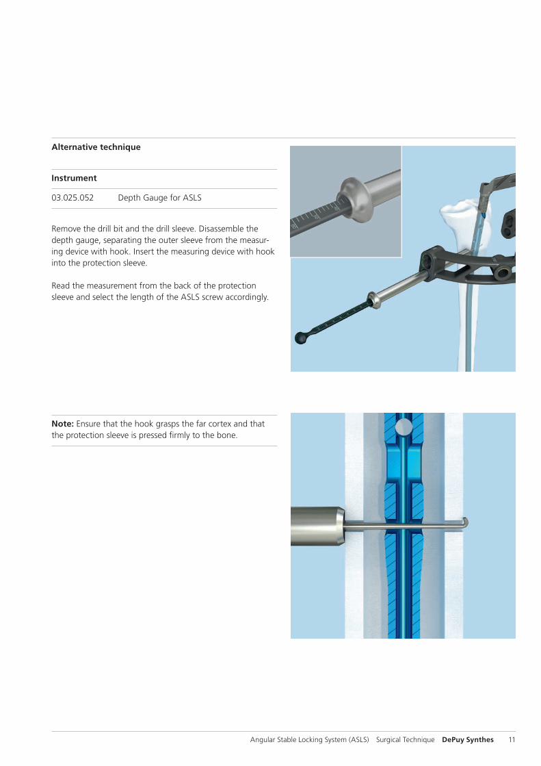
Alternative technique
Instrument
03.025.052 Depth Gauge for ASLS
Remove the drill bit and the drill sleeve. Disassemble the depth gauge, separating the outer sleeve from the measur-ing device with hook. Insert the measuring device with hook into the protection sleeve.
Read the measurement from the back of the protectionsleeve and select the length of the ASLS screw accordingly.
Note: Ensure that the hook grasps the far cortex and that the protection sleeve is pressed fi rmly to the bone.
12 DePuy Synthes Angular Stable Locking System (ASLS) Surgical Technique
Targeted Locking
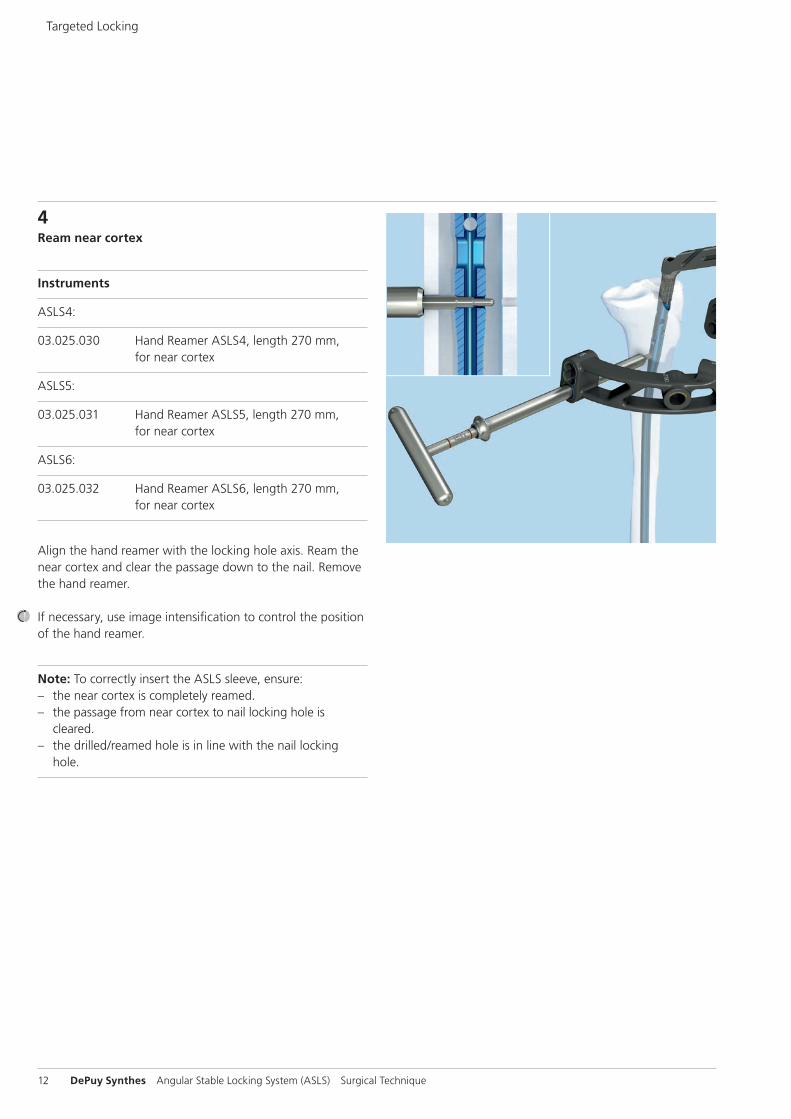
4Ream near cortex
Instruments
ASLS4:
03.025.030 Hand Reamer ASLS4, length 270 mm, for near cortex
ASLS5:
03.025.031 Hand Reamer ASLS5, length 270 mm, for near cortex
ASLS6:
03.025.032 Hand Reamer ASLS6, length 270 mm, for near cortex
Align the hand reamer with the locking hole axis. Ream the near cortex and clear the passage down to the nail. Remove the hand reamer.
If necessary, use image intensification to control the position of the hand reamer.
Note: To correctly insert the ASLS sleeve, ensure: – the near cortex is completely reamed. – the passage from near cortex to nail locking hole is
cleared. – the drilled/reamed hole is in line with the nail locking
hole.

Angular Stable Locking System (ASLS) Surgical Technique DePuy Synthes 13
Alternative technique
Instruments
ASLS4:
03.025.134 Reamer ASLS4, length 268 mm, for near cortex, for Quick Coupling
ASLS5:
03.025.135 Reamer ASLS5, length 288 mm, for near cortex, for Quick Coupling
ASLS6:
03.025.136 Reamer ASLS6, length 288 mm, for near cortex, for Quick Coupling
Use a power driven reamer to open the near cortex. Align the reamer with the locking hole axis and ream the near cortex. Once the large diameter of the reamer passes through the near cortex, stop reaming immediately. Remove the reamer.
If necessary, clear the passage down to the nail with the hand reamer.
If necessary, use image intensification to control the positionof the reamer.
Precaution: Ensure that the reamer does not damage the nail.
Continue with chapter “Screw insertion” on page 26.

14 DePuy Synthes Angular Stable Locking System (ASLS) Surgical Technique
1Align image
The techniques for distal locking apply. Align the image in-tensifier with the desired locking hole until a perfect circle is visible in the center of the screen.
Note: Ensure that the image displayed on the image intensi-fier mirrors the actual image in all axes.
Freehand Locking
2Make incision
Using image intensification, place a long K-wire or alternative long instrument on the skin over the center of the hole to mark the incision point.
Make a skin incision with a scalpel blade at this location.
Note: Check the reduction, correct alignment of the frag-ments, and leg length before locking.

Angular Stable Locking System (ASLS) Surgical Technique DePuy Synthes 15
3Drill through both cortices
Instruments
511.300 Radiolucent Drive
ASLS4:
03.025.124 Drill Bit ASLS4, length 145 mm, 3-flute, for RDL
ASLS5:
03.025.125 Drill Bit ASLS5, length 145 mm, 3-flute, for RDL
ASLS6:
03.025.126 Drill Bit ASLS6, length 145 mm, 3-flute, for RDL
Attach the appropriate drill bit to the radiolucent drive. Using image intensification, insert the tip of the drill bit through the incision and to the bone.
Incline the drive to center the tip of the drill bit over the lock-ing hole. The drill bit should nearly fill the circle of the lock-ing hole. Hold the drill bit in this position and drill through both cortices. Stop drilling immediately after the tip of the drill penetrates the far cortex. Remove the drill bit.
Precaution: Follow all recommended techniques for screw/bolt insertion for the respective nail system. When using monocortical locking screws, stop drilling immediately after penetrating the near cortex.

16 DePuy Synthes Angular Stable Locking System (ASLS) Surgical Technique
Freehand Locking
Alternative technique
Instruments
ASLS4:
03.025.082 Drill Bit ASLS4, length 150 mm, 3-flute, for Quick Coupling
ASLS5:
03.025.083 Drill Bit ASLS5, length 150 mm, 3-flute, for Quick Coupling
ASLS6:
03.025.084 Drill Bit ASLS6, length 150 mm, 3-flute, for Quick Coupling
Standard freehand locking technique can be performed without the radiolucent drive. Use the appropriate drill bit shown in the table above.
Angular Stable Locking System (ASLS) Surgical Technique DePuy Synthes 17
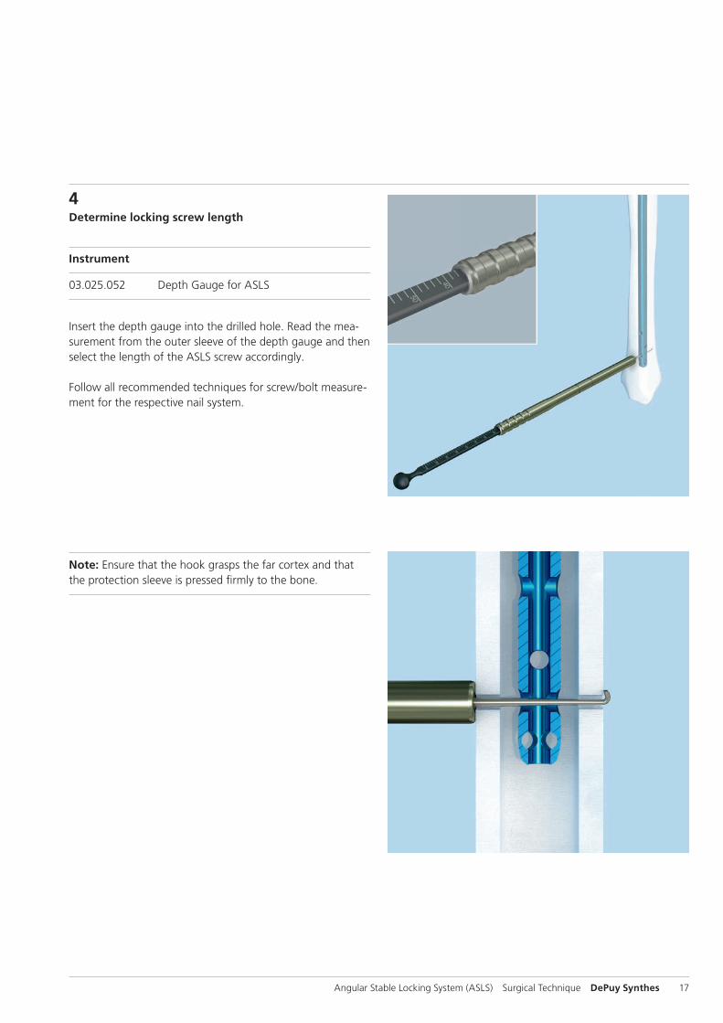
4Determine locking screw length
Instrument
03.025.052 Depth Gauge for ASLS
Insert the depth gauge into the drilled hole. Read the mea-surement from the outer sleeve of the depth gauge and then select the length of the ASLS screw accordingly.
Follow all recommended techniques for screw/bolt measure-ment for the respective nail system.
Note: Ensure that the hook grasps the far cortex and that the protection sleeve is pressed fi rmly to the bone.
18 DePuy Synthes Angular Stable Locking System (ASLS) Surgical Technique
Freehand Locking
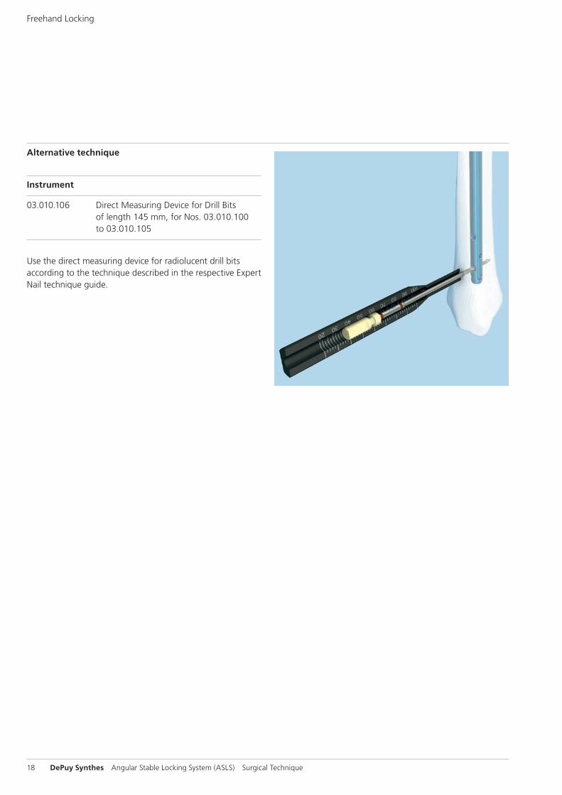
Alternative technique
Instrument
03.010.106 Direct Measuring Device for Drill Bits of length 145 mm, for Nos. 03.010.100 to 03.010.105
Use the direct measuring device for radiolucent drill bits according to the technique described in the respective Expert Nail technique guide.

Angular Stable Locking System (ASLS) Surgical Technique DePuy Synthes 19
5Ream near cortex
Instruments
ASLS4:
03.025.030 Hand Reamer ASLS4, length 270 mm, for near cortex
ASLS5:
03.025.031 Hand Reamer ASLS5, length 270 mm, for near cortex
ASLS6:
03.025.032 Hand Reamer ASLS6, length 270 mm, for near cortex
Align the hand reamer with the locking hole axis. Ream the near cortex and clear the passage down to the nail. Remove the hand reamer.
If necessary, use image intensifi cation to control the position of the hand reamer.
Note: To correctly insert the ASLS sleeve, ensure: – the near cortex is completely reamed. – the passage from near cortex to nail locking hole is
cleared. – the drilled/reamed hole is in line with the nail locking
hole.
20 DePuy Synthes Angular Stable Locking System (ASLS) Surgical Technique
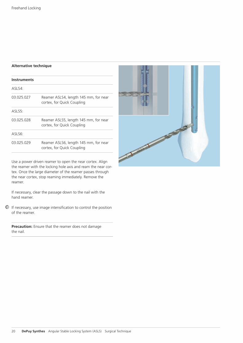
Alternative technique
Instruments
ASLS4:
03.025.027 Reamer ASLS4, length 145 mm, for near cortex, for Quick Coupling
ASLS5:
03.025.028 Reamer ASLS5, length 145 mm, for near cortex, for Quick Coupling
ASLS6:
03.025.029 Reamer ASLS6, length 145 mm, for near cortex, for Quick Coupling
Use a power driven reamer to open the near cortex. Align the reamer with the locking hole axis and ream the near cor-tex. Once the large diameter of the reamer passes through the near cortex, stop reaming immediately. Remove the reamer.
If necessary, clear the passage down to the nail with the hand reamer.
If necessary, use image intensifi cation to control the positionof the reamer.
Precaution: Ensure that the reamer does not damage the nail.
Freehand Locking

1–2 mm
Angular Stable Locking System (ASLS) Surgical Technique DePuy Synthes 21
1Mount sleeve
Instruments
ASLS4:
08.025.032.01S Sleeve for ASLS, resorbable, sterile
ASLS5:
08.025.044.01S Sleeve for ASLS, resorbable, sterile
ASLS6:
08.025.057.01S Sleeve for ASLS, resorbable, sterile
Select the appropriate sleeve.
Insert the sleeve so that the sleeve lip is facing the screw head. Thread the ASLS sleeve onto the ASLS screw. The screw tip will protrude approximately 2 mm beyond the sleeve.
Note: The sleeve is positioned correctly when gold is visible on either side of the sleeve and the screw tip protrudes 1–2 mm beyond the sleeve.
Precautions: – Do not use ASLS screws without sleeves. – When mounting the sleeve, stop threading the sleeve
once resistance increases. Resistance occurs when the sleeve expands as it moves onto the larger diameter of the screw. An expanded sleeve will prevent screw/sleeve in-sertion into a locking hole.
Screw Insertion
Sleeve lip
22 DePuy Synthes Angular Stable Locking System (ASLS) Surgical Technique
Screw Insertion
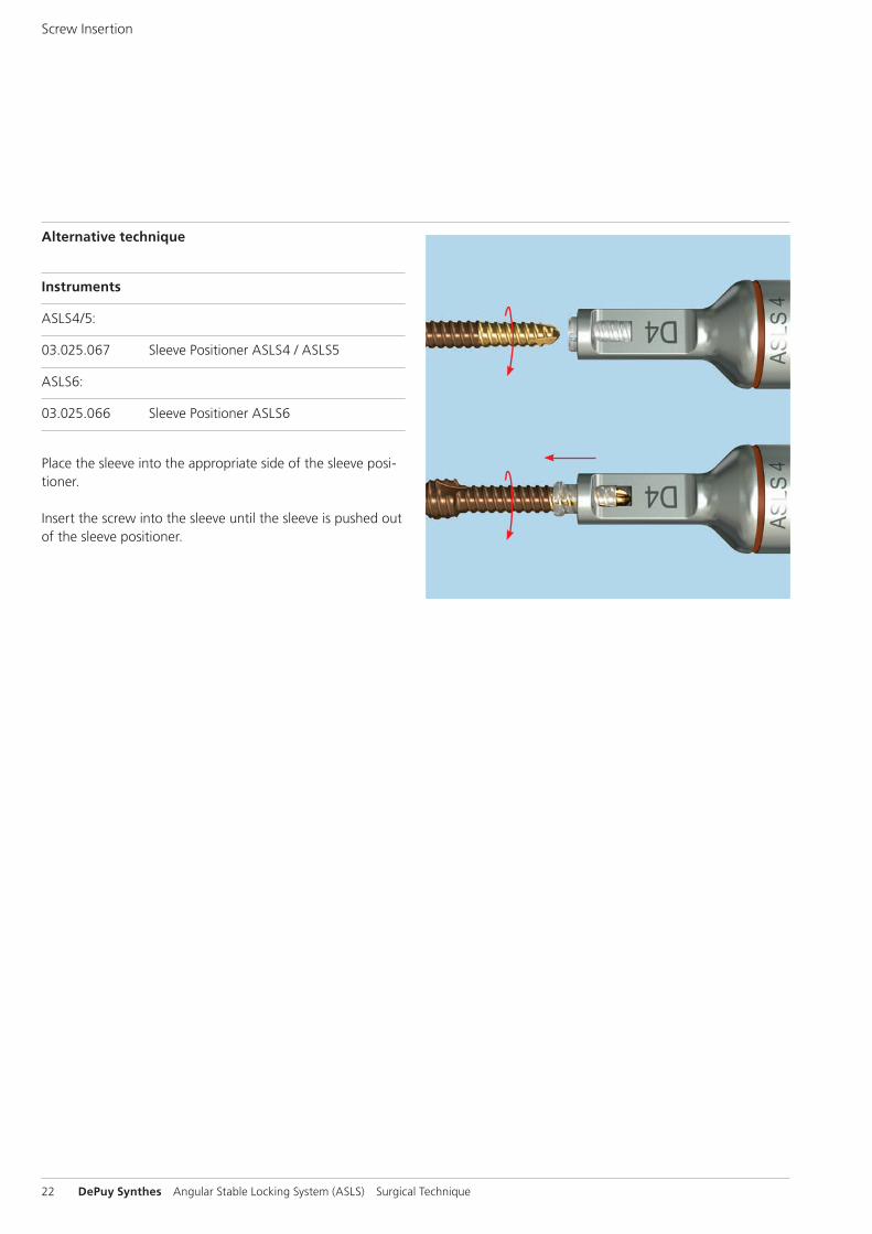
Alternative technique
Instruments
ASLS4/5:
03.025.067 Sleeve Positioner ASLS4 / ASLS5
ASLS6:
03.025.066 Sleeve Positioner ASLS6
Place the sleeve into the appropriate side of the sleeve posi-tioner.
Insert the screw into the sleeve until the sleeve is pushed out of the sleeve positioner.

Angular Stable Locking System (ASLS) Surgical Technique DePuy Synthes 23
2Push screw/sleeve assembly into locking hole
Instruments
03.010.063 Protection Sleeve 12.0/8.0, length 188 mm (for Expert nails)
03.025.040 Protection Sleeve 11.0/8.0, length 188 mm (for other nail systems)
03.010.107 Screwdriver Stardrive, SD25, length 330 mm
ASLS4:
03.010.064 Drill Sleeve 8.0/3.2, for No. 03.010.063
03.010.069 Trocar B 3.2 mm, for No. 03.010.064
ASLS5:
03.010.065 Drill Sleeve 8.0/4.2, for No. 03.010.063
03.010.070 Trocar B 4.2 mm, for No. 03.010.065
ASLS6:
03.010.066 Drill Sleeve 8.0/5.0, for No. 03.010.063
03.010.071 Trocar B 5.0 mm, for No. 03.010.066
Assemble the appropriate protection sleeve, drill sleeve and trocar and advance the assembly to the bone. Remove the drill sleeve and trocar.
Mount the ASLS screw/sleeve assembly onto the screwdriver.

24 DePuy Synthes Angular Stable Locking System (ASLS) Surgical Technique
Optional technique
Instrument
399.500 Hammer 100 g
If necessary, lightly hammer to insert the screw into the nail locking hole.
Push the ASLS screw/sleeve assembly through the protection sleeve, near cortex, and into the nail locking hole. If neces-sary, lightly tap the screwdriver to insert the screw/sleeve into the locking hole.
Precaution: Do not rotate the screwdriver until the sleeve is seated in the locking hole.
Note: If the screw/sleeve assembly cannot be pushed to the nail stop, use the appropriate reamer to completely open the near cortex. (see previous step “Ream near cortex”)
Screw Insertion
Angular Stable Locking System (ASLS) Surgical Technique DePuy Synthes 25
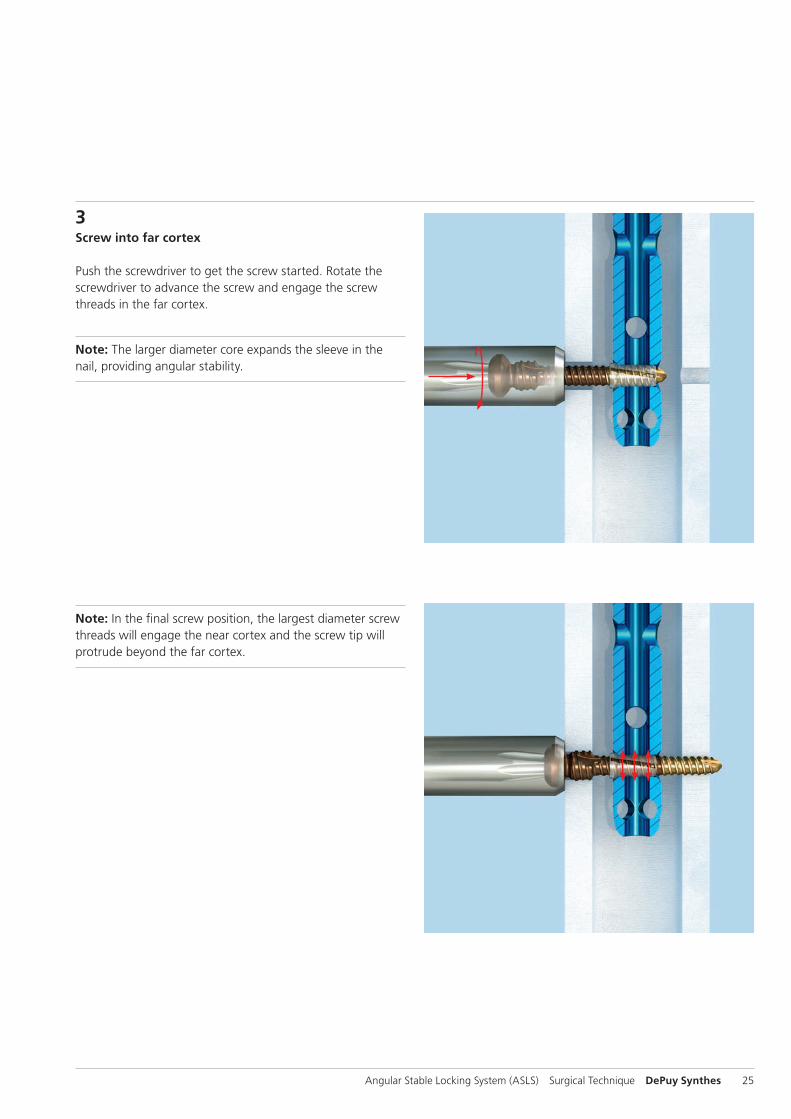
3Screw into far cortex
Push the screwdriver to get the screw started. Rotate the screwdriver to advance the screw and engage the screw threads in the far cortex.
Note: The larger diameter core expands the sleeve in the nail, providing angular stability.
Note: In the final screw position, the largest diameter screw threads will engage the near cortex and the screw tip will protrude beyond the far cortex.

26 DePuy Synthes Angular Stable Locking System (ASLS) Surgical Technique
Note: To prevent over-insertion of the ASLS screw, use a protection sleeve during screw insertion. Ensure that the protection sleeve is pressed to the bone. Advance the screw until the engraved line on the screwdriver shaft meets the edge of the protection sleeve.
After insertion of all screws, use image intensifi cation to en-sure that reduction is maintained that the screw heads are down the bone and the screws are not over inserted.
4Intraoperative screw exchange
Instruments
03.010.107 Screwdriver Stardrive, T25, length 330 mm
03.010.112 Holding Sleeve, with Locking Device
Using standard technique, remove the ASLS screw with the screwdriver and if necessary, by pulling with the holding sleeve.
Note: Since the sleeve remains in the nail, it does not need to be removed and exchanged.
Screw Insertion

Angular Stable Locking System (ASLS) Surgical Technique DePuy Synthes 27
Implant Removal
1Remove screws
Instruments
03.010.107 Screwdriver Stardrive, T25, length 330 mm
03.010.112 Holding Sleeve, with Locking Device
Using standard technique, remove ASLS screws with the screwdriver and if necessary, the holding sleeve.
2Remove nail
Remove the nail using standard technique for the respective nail system.
Note: The sleeves remain in the nail if not fully resorbed and can be removed with the nail during nail removal.

D1
D2
D3
28 DePuy Synthes Angular Stable Locking System (ASLS) Surgical Technique
ASLS4 ASLS5 ASLS6
Length B 4 mm B 5 mm B 6 mm
26 mm 04.025.416S
28 mm 04.025.418S
30 mm 04.025.420S 04.025.520S
32 mm 04.025.422S 04.025.522S 04.025.622S
34 mm 04.025.424S 04.025.524S 04.025.624S
36 mm 04.025.426S 04.025.526S 04.025.626S
38 mm 04.025.428S 04.025.528S 04.025.628S
40 mm 04.025.430S 04.025.530S 04.025.630S
42 mm 04.025.432S 04.025.532S 04.025.632S
44 mm 04.025.434S 04.025.534S 04.025.634S
46 mm 04.025.436S 04.025.536S 04.025.636S
48 mm 04.025.438S 04.025.538S 04.025.638S
50 mm 04.025.440S 04.025.540S 04.025.640S
52 mm 04.025.442S 04.025.542S 04.025.642S
54 mm 04.025.444S 04.025.544S 04.025.644S
56 mm 04.025.446S 04.025.546S 04.025.646S
58 mm 04.025.448S 04.025.548S 04.025.648S
60 mm 04.025.450S 04.025.550S 04.025.650S
62 mm 04.025.452S 04.025.552S 04.025.652S
64 mm 04.025.454S 04.025.554S 04.025.654S
66 mm 04.025.456S 04.025.556S 04.025.656S
68 mm 04.025.458S 04.025.558S 04.025.658S
70 mm 04.025.460S 04.025.560S 04.025.660S
72 mm 04.025.462S 04.025.562S 04.025.662S
74 mm 04.025.464S 04.025.564S 04.025.664S
76 mm 04.025.466S 04.025.566S 04.025.666S
78 mm 04.025.468S 04.025.568S 04.025.668S
80 mm 04.025.470S 04.025.570S 04.025.670S
85 mm 04.025.575S 04.025.675S
90 mm 04.025.580S 04.025.680S
95 mm 04.025.585S 04.025.685S
100 mm 04.025.590S 04.025.690S
105 mm 04.025.695S
110 mm 04.025.700S
115 mm 04.025.705S
120 mm 04.025.710S
125 mm 04.025.715S
Implants
ASLS Screws
– Titanium-6% aluminium-7% niobium alloy (TAN) – Fully threaded shaft with 3 diameters
– D1: Provides purchase in reamed near cortex – D2: Expands sleeve, thus providing angular stability – D3: Holds unexpanded sleeve for screw insertion,
provides purchase in far cortex – Self-tapping, blunt tip – Stardrive SD25 recess – Available in diameters of 4.0 mm (ASLS4), 5.0 mm
(ASLS5) and 6.0 mm (ASLS6) – Sterile-packed

Angular Stable Locking System (ASLS) Surgical Technique DePuy Synthes 29
ASLS sleeves
– 70:30 poly (L-lactide-co-D,L-lactide) – Bioresorbable, provides 80% decreased
fracture site motion during first 12 weeks of healing – Gradually degrades within 2 years (resorption rate varies
per patient and implant site) – Inner thread for secure fit to screw – Expands in nail locking hole – Available in diameters of 4 mm (ASLS4), 5 mm (ASLS5)
and 6 mm (ASLS6) – Sterile-packed
ASLS4 ASLS5 ASLS6
Diameter B 4 mm B 5 mm B 6 mm
08.025.032.01S 08.025.044.01S 08.025.057.01S

30 DePuy Synthes Angular Stable Locking System (ASLS) Surgical Technique
ASLS Compatibility with Existing Nails
The Angular Stable Locking System is compatible with all Synthes nailing systems fulfilling the following criteria: – Made of Titanium – Cannulated
Nailing System B Nail ASLS4 ASLS5 ASLS6 (mm) B 4 mm B 5 mm B 6 mm (brown) (light blue) (dark purple)
Humerus
Expert Humeral & Proximal Humeral Nail (EHN & EPHN) 7, 9, 11 • MultiLoc Proximal Humeral Nail 8, 9.5 •
Proximal Femur
Proximal Femoral Nail Antirotation - long (PFNa - long) 9, 10, 12, 14 •
Trochanteric Fixation Nail – long (TFN - long) 10, 11, 12 •
Proximal Femoral Nail – long (PFN - long) 10, 12, 14 •
Femur
Expert Lateral Femoral Nail (Expert LFN) 9 –13 •
14–16 •
Expert Retrograde/Antegrade Femoral Nail (Expert R/AFN) 9–13 •
14–15 •
Cannulated Femoral Nail (CFN) 10–15 •
* Only compatible with cannulated nails
Angular Stable Locking System (ASLS) Surgical Technique DePuy Synthes 31
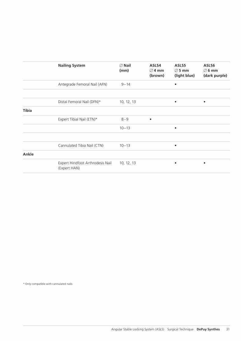
Nailing System B Nail ASLS4 ASLS5 ASLS6 (mm) B 4 mm B 5 mm B 6 mm (brown) (light blue) (dark purple)
Antegrade Femoral Nail (AFN) 9–14 •
Distal Femoral Nail (DFN)* 10, 12, 13 • •
Tibia
Expert Tibial Nail (ETN)* 8–9 •
10–13 •
Cannulated Tibia Nail (CTN) 10–13 •
Ankle
Expert Hindfoot Arthrodesis Nail 10, 12, 13 • • (Expert HAN)
* Only compatible with cannulated nails
32 DePuy Synthes Angular Stable Locking System (ASLS) Surgical Technique
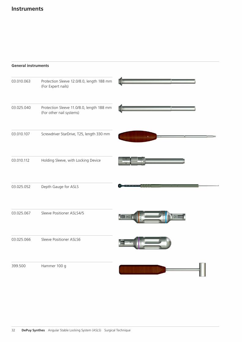
Instruments
General instruments
03.010.063 Protection Sleeve 12.0/8.0, length 188 mm (For Expert nails)
03.025.040 Protection Sleeve 11.0/8.0, length 188 mm (For other nail systems)
03.010.107 Screwdriver StarDrive, T25, length 330 mm
03.010.112 Holding Sleeve, with Locking Device
03.025.052 Depth Gauge for ASLS
03.025.067 Sleeve Positioner ASLS4/5
03.025.066 Sleeve Positioner ASLS6
399.500 Hammer 100 g
Angular Stable Locking System (ASLS) Surgical Technique DePuy Synthes 33
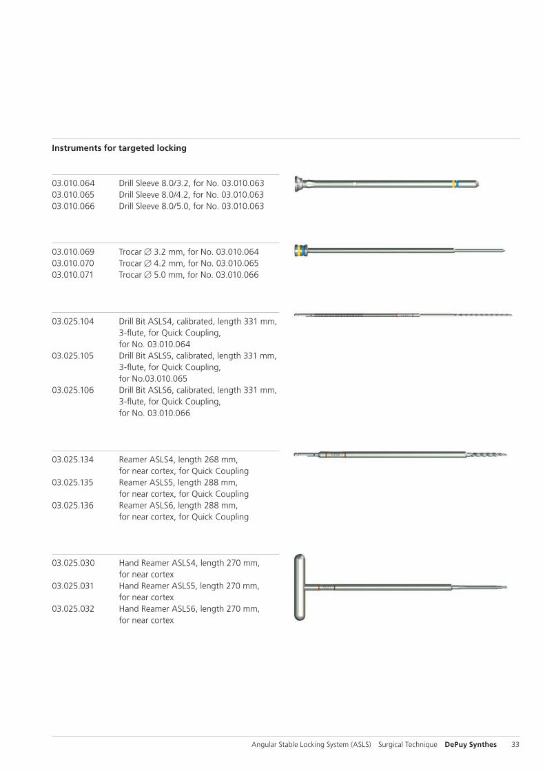
Instruments for targeted locking
03.010.064 Drill Sleeve 8.0/3.2, for No. 03.010.06303.010.065 Drill Sleeve 8.0/4.2, for No. 03.010.06303.010.066 Drill Sleeve 8.0/5.0, for No. 03.010.063
03.010.069 Trocar B 3.2 mm, for No. 03.010.06403.010.070 Trocar B 4.2 mm, for No. 03.010.06503.010.071 Trocar B 5.0 mm, for No. 03.010.066
03.025.104 Drill Bit ASLS4, calibrated, length 331 mm, 3-flute, for Quick Coupling,
for No. 03.010.06403.025.105 Drill Bit ASLS5, calibrated, length 331 mm, 3-flute, for Quick Coupling, for No.03.010.065 03.025.106 Drill Bit ASLS6, calibrated, length 331 mm, 3-flute, for Quick Coupling, for No. 03.010.066
03.025.134 Reamer ASLS4, length 268 mm, for near cortex, for Quick Coupling
03.025.135 Reamer ASLS5, length 288 mm, for near cortex, for Quick Coupling03.025.136 Reamer ASLS6, length 288 mm, for near cortex, for Quick Coupling
03.025.030 Hand Reamer ASLS4, length 270 mm, for near cortex03.025.031 Hand Reamer ASLS5, length 270 mm, for near cortex03.025.032 Hand Reamer ASLS6, length 270 mm, for near cortex

34 DePuy Synthes Angular Stable Locking System (ASLS) Surgical Technique
03.025.082 Drill Bit ASLS4, length 150 mm, 3-flute, for Quick Coupling03.025.083 Drill Bit ASLS5, length 150 mm, 3-flute, for Quick Coupling03.025.084 Drill Bit ASLS6, length 150 mm, 3-flute, for Quick Coupling
Instruments for freehand locking
03.025.027 Reamer ASLS4, length 145 mm, for near cortex, for Quick Coupling03.025.028 Reamer ASLS5, length 145 mm, for near cortex, for Quick Coupling 03.025.029 Reamer ASLS6, length 145 mm, for near cortex, for Quick Coupling
03.025.124 Drill Bit ASLS4, length 145 mm, 3-flute, for RDL
03.025.125 Drill Bit ASLS5, length 145 mm, 3-flute, for RDL03.025.126 Drill Bit ASLS6, length 145 mm, 3-flute, for RDL
03.025.030 Hand Reamer ASLS4, length 270 mm, for near cortex03.025.031 Hand Reamer ASLS5, length 270 mm, for near cortex03.025.032 Hand Reamer ASLS6, length 270 mm, for near cortex
Instruments

Angular Stable Locking System (ASLS) Surgical Technique DePuy Synthes 35
Vario Case
68.025.001 Vario Case for ASLS Instruments, size 1/1, without Contents
68.025.003 Tray, for Instruments ASLS6, size 1/2, long, for Vario Case No. 68.025.001
689.507 Lid (Stainless Steel), size 1/1, for Vario Case
36 DePuy Synthes Angular Stable Locking System (ASLS) Surgical Technique
Power Tools
Compact Air Drive II
511.701 Compact Air Drive II
511.300 Radiolucent Drive
511.730 Chuck with Key, for Compact Air Drive and Power Drive
511.750 AO/ASIF Quick Coupling, for Compact Air Drive and Power Drive

Angular Stable Locking System (ASLS) Surgical Technique DePuy Synthes 37
Sets
68.025.001 Vario Case for ASLS Instruments, size 1/1, without Contents
689.507 Lid (Stainless Steel), size 1/1, for Vario Case
General instruments
03.010.112 Holding Sleeve, with Locking Device
399.500 Hammer, 100 g
03.010.063 Protection Sleeve 12.0/8.0, length 188 mm
03.010.107 Screwdriver Stardrive, T25, length 330 mm
03.025.040 Protection Sleeve 11.0/8.0, length 188 mm
03.025.052 Depth Gauge for ASLS
03.025.067 Sleeve Positioner ASLS4/5
03.025.066 Sleeve Positioner ASLS 6
ASLS4
03.010.064 Drill Sleeve 8.0/3.2, for No. 03.010.063
03.010.069 Trocar B 3.2 mm, for No. 03.010.064
03.025.027 Reamer ASLS4, length 145 mm, for near cortex, for Quick Coupling
03.025.082 Drill Bit ASLS4, length 150 mm, 3-flute, for Quick Coupling
03.025.104 Drill Bit ASLS4, calibrated, length 331 mm, 3-flute, for Quick Coupling, for No. 03.010.064
03.025.124 Drill Bit ASLS4, length 145 mm, 3-flute, for RDL
03.025.134 Reamer ASLS4, length 268 mm, for near cortex, for Quick Coupling
03.025.030 Hand Reamer ASLS4, length 270 mm, for near cortex
38 DePuy Synthes Angular Stable Locking System (ASLS) Surgical Technique
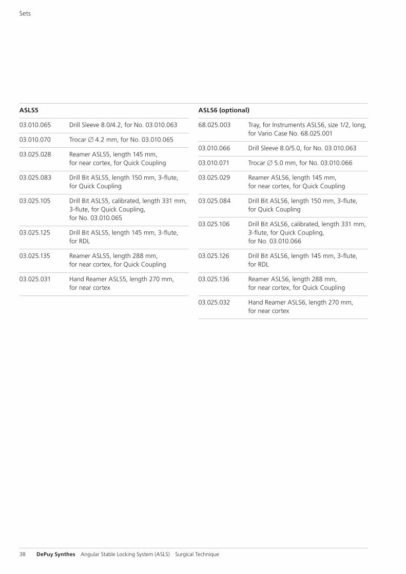
ASLS5
03.010.065 Drill Sleeve 8.0/4.2, for No. 03.010.063
03.010.070 Trocar B 4.2 mm, for No. 03.010.065
03.025.028 Reamer ASLS5, length 145 mm, for near cortex, for Quick Coupling
03.025.083 Drill Bit ASLS5, length 150 mm, 3-flute, for Quick Coupling
03.025.105 Drill Bit ASLS5, calibrated, length 331 mm, 3-flute, for Quick Coupling, for No. 03.010.065
03.025.125 Drill Bit ASLS5, length 145 mm, 3-flute, for RDL
03.025.135 Reamer ASLS5, length 288 mm, for near cortex, for Quick Coupling
03.025.031 Hand Reamer ASLS5, length 270 mm, for near cortex
ASLS6 (optional)
68.025.003 Tray, for Instruments ASLS6, size 1/2, long, for Vario Case No. 68.025.001
03.010.066 Drill Sleeve 8.0/5.0, for No. 03.010.063
03.010.071 Trocar B 5.0 mm, for No. 03.010.066
03.025.029 Reamer ASLS6, length 145 mm, for near cortex, for Quick Coupling
03.025.084 Drill Bit ASLS6, length 150 mm, 3-flute, for Quick Coupling
03.025.106 Drill Bit ASLS6, calibrated, length 331 mm, 3-flute, for Quick Coupling, for No. 03.010.066
03.025.126 Drill Bit ASLS6, length 145 mm, 3-flute, for RDL
03.025.136 Reamer ASLS6, length 288 mm, for near cortex, for Quick Coupling
03.025.032 Hand Reamer ASLS6, length 270 mm, for near cortex
Sets
Angular Stable Locking System (ASLS) Surgical Technique DePuy Synthes 39
Bibliography
Angular stable locking of intramedullary nails
Epari DR, Kassi JP, Schell H, Duda GN (2007) Timely fracture- healing requires optimization of axial fixation stability. J Bone Joint Surg Am.89(7):1575-85
Kaspar K, Schell H, Seebeck P, Thompson MS, Schutz M, Haas NP, Duda GN (2005) Angle stable locking reduces inter-fragmentary movements and promotes healing after un-reamed nailing. Study of a displaced osteotomy model in sheep tibiae. J Bone Joint Surg Am 87(9):2028-37
Schell H, Epari DR, Kassi JP, Bragulla H, Bail HJ, Duda GN (2005) The course of bone healing is influenced by the initial shear fixation stability. J Orthop Res 23(5):1022-8
Characteristics of 70:30 poly L/DL-lactide
Al-Sukhun J, Törnwall J, Lindqvist C, Kontio R (2006) Biore-sorbable Poly-L/DL-Lactide (P[L/DL]LA 70/30) Plates Are Reli-able for Repairing Large Inferior Orbital Wall Bony Defects: A Pilot Study. J Oral Maxillofac Surg. 64:47-55
Landes CA, Ballon A, Roth C (2006) In-patient versus in vitro degradation of P(L/DL)LA and PLGA. J Biomed Mater Res B Appl Biomater 76(2):403-11
Landes CA, Kriener S, Menzer M, Kovàcs F (2003) Resorb-able Plate Osteosynthesis of Dislocated or Pathological Man-dibular Fractures: A Prospective Clinical Trial of Two Amor-phous L-/DL-Lactide Copolymer 2-mm Miniplate Systems. Plast Reconstr Surg 111(2):601-10.
Prokop A, Jubel A, Hahn A, Dietershagen U, Bleidistel M., Peters C, Höfl A, Rehm KE (2005) A comparative radiological assessment of polylactide pins over 3 years in vivo. Biomate-rials, 26(19):4129-38.
40 DePuy Synthes Angular Stable Locking System (ASLS) Surgical Technique
MRI Information
Torque, Displacement and Image Artifacts according to ASTM F 2213-06, ASTM F 2052-06e1 and ASTM F2119-07Non-clinical testing of worst case scenario in a 3 T MRI system did not reveal any relevant torque or displacement of the construct for an experimentally measured local spatial gradient of the magnetic field of 3.69 T/m. The largest image artifact extended approximately 169 mm from the construct when scanned using the Gradient Echo (GE). Testing was conducted on a 3 T MRI system.
Radio-Frequency-(RF-)induced heating according to ASTM F2182-11aNon-clinical electromagnetic and thermal testing of worst case scenario lead to peak temperature rise of 9.5 °C with an average temperature rise of 6.6 °C (1.5 T) and a peak temperature rise of 5.9 °C (3 T) under MRI Conditions using RF Coils (whole body averaged specific absorption rate [SAR] of 2 W/kg for 6 minutes [1.5 T] and for 15 minutes [3 T]).
Precautions: The above mentioned test relies on non-clini-cal testing. The actual temperature rise in the patient will depend on a variety of factors beyond the SAR and time of RF application. Thus, it is recommended to pay particular attention to the following points: – It is recommended to thoroughly monitor patients under-
going MR scanning for perceived temperature and/or pain sensations.
– Patients with impaired thermoregulation or temperature sensation should be excluded from MR scanning proce-dures.
– Generally, it is recommended to use a MR system with low field strength in the presence of conductive implants. The employed specific absorption rate (SAR) should be reduced as far as possible.
– Using the ventilation system may further contribute to reduce temperature increase in the body.


0123
Synthes GmbHEimattstrasse 34436 OberdorfSwitzerlandTel: +41 61 965 61 11Fax: +41 61 965 66 00www.depuysynthes.com
Not all products are currently available in all markets.
This publication is not intended for distribution in the USA.
All surgical techniques are available as PDF files at www.depuysynthes.com/ifu ©
DeP
uy S
ynth
es T
raum
a, a
div
isio
n of
Syn
thes
Gm
bH. 2
016.
A
ll rig
hts
rese
rved
. 03
6.0
00.
708
DSE
M/T
RM
/011
5/02
84
(2)
08/
16