ANDROID BASED CLOSED LOOP SPEED CONTROL OF DC MOTOR …techpublic.in/volume2issue4/paper10.pdf ·...
14
82 @2018 T.Manjula et.al.| www.techpubic.in International Journal of Global Engineering (IJGE) E- ISSN: 2456-3099 VOL 2 ISSUE 4 (2018) PAGES 82 - 95 Received: 20/03/2018. Published: 15/04/2018 ANDROID BASED CLOSED LOOP SPEED CONTROL OF DC MOTOR VOICE RECOGNITION BY USING WI-FI T.Manjula, Mr.M.Sudhakaran, UG Student, Ganadipathy Tulsi’s Jain Engineering College, Kaniyambadi, Vellore, Associate professor, Ganadipathy Tulsi’s Jain Engineering College, Kaniyambadi, Vellore Abstract The DC motors are widely used for variable speed drive system in industrial applications such as industrial automation, electric traction, aircraft, military equipment, hard disk drives because of their high efficiency, silent operation, compact, reliability and low maintenance. Due to the advancement of wireless technology, there are several connections are introduced such as GSM, Wi-Fi, ZIGBEE and Bluetooth. Each of the connection has their own unique specifications and applications. Among these wireless connections, WI-FI technology often implemented. The speed control was implemented using WI-FI technology to provide communication access from smart phone. Communication plays a major role in day today’s life and can be used as a better tool in control system. It deals with wireless communication and voice recognition and is used to control the motor speed. Microcontroller enables a person to work around independently using a touch screen and voice recognition applications which is interfaced with motors. This can also be controlled through simple voice commands. In addition to this IR sensor is used to sense the motor speed and in turn speed of the motor can be received via WI-FI to the android mobile. Keywords : Android Mobile, ESP8266 WI-FI Module, L293D, PIC16F883, DC Motor, IR Speed Sensor. 1. INTRODUCTION DC motor in different steps is easy compared to AC motors. By the open loop control the DC motor can be operated at any intermediate speed by changing the voltage, armature current etc. But in open loop (Prediction based) control accuracy in speed cannot be obtained. There will not be any feedback to the controller to indicate the change in speed due to load. This disadvantage restricts the use of open loop speed control DC motor in applications where constant speed is essential. To avoid this disadvantage a closed loop technique is implemented where the output measured speed is fed back to the speed controller. In closed loop controller the speed can be maintained by adjusting terminal voltage according the speed difference caused by the load torque. i.e., a fine control of speed can be obtained using closed loop speed control. Android is a software stack for mobile devices that includes an operating system, middleware and key applications. Android boasts a healthy array of connectivity options including Wi-Fi, Bluetooth and wireless data over cellular connection. Voice recognition is carried out by android mobiles in which internal voice recognition is used to pass voice commands to motor which is paired with Wi-Fi Serial Modules which in turn the recognized voice as a string. Microcontroller receives the command
Transcript of ANDROID BASED CLOSED LOOP SPEED CONTROL OF DC MOTOR …techpublic.in/volume2issue4/paper10.pdf ·...

82 @2018 T.Manjula et.al.| www.techpubic.in
International Journal of Global Engineering (IJGE) E- ISSN: 2456-3099
VOL 2 ISSUE 4 (2018) PAGES 82 - 95
Received: 20/03/2018. Published: 15/04/2018
ANDROID BASED CLOSED LOOP SPEED CONTROL OF DC
MOTOR VOICE RECOGNITION BY USING WI-FI
T.Manjula, Mr.M.Sudhakaran,
UG Student, Ganadipathy Tulsi’s Jain Engineering College, Kaniyambadi, Vellore,
Associate professor, Ganadipathy Tulsi’s Jain Engineering College, Kaniyambadi, Vellore
Abstract
The DC motors are widely used for variable speed drive system in industrial applications such as
industrial automation, electric traction, aircraft, military equipment, hard disk drives because of their high
efficiency, silent operation, compact, reliability and low maintenance. Due to the advancement of wireless
technology, there are several connections are introduced such as GSM, Wi-Fi, ZIGBEE and Bluetooth.
Each of the connection has their own unique specifications and applications. Among these wireless
connections, WI-FI technology often implemented. The speed control was implemented using WI-FI
technology to provide communication access from smart phone. Communication plays a major role in day
today’s life and can be used as a better tool in control system. It deals with wireless communication and
voice recognition and is used to control the motor speed. Microcontroller enables a person to work around
independently using a touch screen and voice recognition applications which is interfaced with motors.
This can also be controlled through simple voice commands. In addition to this IR sensor is used to sense
the motor speed and in turn speed of the motor can be received via WI-FI to the android mobile.
Keywords : Android Mobile, ESP8266 WI-FI Module, L293D, PIC16F883, DC Motor, IR Speed
Sensor.
1. INTRODUCTION
DC motor in different steps is easy compared to AC motors. By the open loop control the DC motor
can be operated at any intermediate speed by changing the voltage, armature current etc. But in open loop
(Prediction based) control accuracy in speed cannot be obtained. There will not be any feedback to the
controller to indicate the change in speed due to load. This disadvantage restricts the use of open loop
speed control DC motor in applications where constant speed is essential. To avoid this disadvantage a
closed loop technique is implemented where the output measured speed is fed back to the speed
controller. In closed loop controller the speed can be maintained by adjusting terminal voltage according
the speed difference caused by the load torque. i.e., a fine control of speed can be obtained using closed
loop speed control. Android is a software stack for mobile devices that includes an operating system,
middleware and key applications. Android boasts a healthy array of connectivity options including Wi-Fi,
Bluetooth and wireless data over cellular connection. Voice recognition is carried out by android mobiles
in which internal voice recognition is used to pass voice commands to motor which is paired with Wi-Fi
Serial Modules which in turn the recognized voice as a string. Microcontroller receives the command
83 @2018 T.Manjula et.al.| www.techpubic.in
International Journal of Global Engineering (IJGE) E- ISSN: 2456-3099
VOL 2 ISSUE 4 (2018) PAGES 82 - 95
Received: 20/03/2018. Published: 15/04/2018
voice output from the android mobile and there are certain predefined conditions in controller. If it
satisfies the condition then it sends the signal to driver circuit. Using this we can also find the voltage and
current taken by the DC motor. DC motor is sensed by the speed sensor. The sensed output (speed,
temperature, voltage and current rating) is given back to the android mobile via WI-FI.
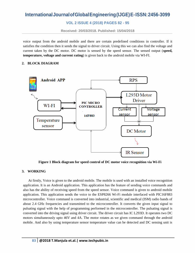
2. BLOCK DIAGRAM
Figure 1 Block diagram for speed control of DC motor voice recognition via Wi-Fi
3. WORKING
At firstly, Voice is given to the android mobile. The mobile is used with an installed voice recognition
application. It is an Android application. This application has the feature of sending voice commands and
also has the ability of receiving speed from the speed sensor. Voice command is given to android mobile
application. This application sends the voice to the ESP8266 Wi-Fi module interfaced with PIC16F883
microcontroller. Voice command is converted into industrial, scientific and medical (ISM) radio bands of
about 2.4 GHz frequencies and transmitted to the microcontroller. It converts the given input signal to
pulsating signal with the help of programming performed in the microcontroller. The pulsating signal is
converted into the driving signal using driver circuit. The driver circuit has IC L293D. It operates two DC
motors simultaneously upto 46V and 4A. The motor rotates as we given command through the android
mobile. And also by using temperature sensor temperature value can be detected and DC sensing unit is

84 @2018 T.Manjula et.al.| www.techpubic.in
International Journal of Global Engineering (IJGE) E- ISSN: 2456-3099
VOL 2 ISSUE 4 (2018) PAGES 82 - 95
Received: 20/03/2018. Published: 15/04/2018
used to sense the voltage and current taken by the DC motor. Speed is sensed by the IR sensor. It is a
wireless sensor and it is directly connected to the PIC microcontroller. The speed of the motor can be
displayed by android mobile via Wi-Fi.
4. HARDWARE COMPONENTS
A. POWER SUPPLY
Figure 2 Power supply circuit diagram
B. ESP8266 WI-FI MODULE
ESP8266 is an impressive, low cost WIFI module suitable for adding WIFI functionality to an
existing microcontroller project via a UART serial connection. The feature list is impressive and
includes: 802.11 b/g/n protocol Wi-Fi Direct (P2P), soft-AP Integrated TCP/IP protocol stack. The
ESP8266 requires 3.3V power–do not power it with 5 volts. The ESP8266 needs to communicate via
serial at 3.3V and does not have 5V tolerant inputs.
C. MICROCONTROLLER
In this project uses PIC Microcontroller of 16F883 contains 28 pins with 3 ports of Port A,B,C. It
has 14 analog inputs and 14 digital I/O’s. Operating frequency is 20MHz crystal oscillator frequency.
Then it converts given input signal into pulsating signal (PWM). The reason for using PIC has variety
of choices (8-bit to 32-bit), low cost, low power, reasonable size, convenient packaging, through hole,
surface mount.
D. MOTOR DRIVER

85 @2018 T.Manjula et.al.| www.techpubic.in
International Journal of Global Engineering (IJGE) E- ISSN: 2456-3099
VOL 2 ISSUE 4 (2018) PAGES 82 - 95
Received: 20/03/2018. Published: 15/04/2018
The L293D is an integrated monolithic circuit in a 15-lead Multiwatt and PowerSO20 packages.
It is a high voltage, high current dual full-bridge driver designed to accept standard TTL logic levels
and drive inductive loads such as relays, solenoids, DC and stepping motors. Two enable inputs are
provided to enable or disable the device independently of the input signals. The emitters of the lower
transistors of each bridge are connected together and the corresponding external terminal can be used
for the connection of an external sensing resistor. An additional supply input is provided so that the
logic works at a lower voltage.
E. TEMPERATURE SENSOR
The LM35 is an integrated circuit sensor that can be used to measure temperature with an electrical
output propositional to the temperature. Output voltage is linearly propositional to the Celsius
(centigrade) temperature.
F. DC SENSING UNIT
I) VOLTAGE SENSOR
A voltage sensor is going to be able to determine and even monitor and measure the voltage
supply. It is then able to take those measurements and turn them into a signal that one will then be able
to read. The signal will often go into a specialized electronic device for recording, but sometimes, an
observer will be present to manually read the sensor output.
II) CURRENT SENSOR
A current sensor is a device that detects electric current in a wire, and generates a signal
proportional to that current. The generated signal could be analog voltage or current or even a digital
output. The generated signal can be then used to display the measured current in an ammeter, or can be
stored for further analysis in a data acquisition system, or can be used for the purpose of control.
G. DC MOTOR
In this project we are using the DC shunt motor which is 12V DC motor. It has 1 pole with
thick shunt winding connected parallel to the armature. The DC motor runs at various speed through
the logic states from the L293D IC then the transistor BC547 acts as a switch which operates the relay
to drive the motor as per the given speed. DC shunt motor has many wide applications. In industrial,
Lathes, Drills, Boring Mills, Shapers , Spinning, and weaving machines etc.
F. IR SPEED SENSOR
IR Sensor is a speed sensing device used to sense the speed of the DC Motor and received back
to the android mobile via Wi-Fi for user purpose.

86 @2018 T.Manjula et.al.| www.techpubic.in
International Journal of Global Engineering (IJGE) E- ISSN: 2456-3099
VOL 2 ISSUE 4 (2018) PAGES 82 - 95
Received: 20/03/2018. Published: 15/04/2018
5. SOFTWARE
A. Proteus
Proteus is software for microprocessor simulation, schematic capture, and printed circuit board
(PCB) design. It is developed by Labcenter Electronics. Proteus (Processor for text Easy to use) is a
fully functional, procedural programming language created in 1998 by Simone Zanella. Proteus
incorporates many functions derived from several other languages: C, BASIC, Assembly, etc. It is
especially versatile in dealing with strings, having hundreds of dedicated functions; this makes it one
of the richest languages for text manipulation. Proteus was initially created as a multiplatform (DOS,
Windows, UNIX) system utility, to manipulate text and binary files and to create CGI scripts. The
language was later focused on Windows, by adding hundreds of specialized functions for: network and
serial communication, database interrogation, system service creation, console applications, keyboard
emulation, ISAPI scripting.
B. CCS COMPILER
A compiler is a computer program (or set of programs) that transforms source code written in a
programming language (the source language) into another computer language (the target language,
often having a binary form known as object code). The most common reason for wanting to transform
source code is to create an executable program.
C. LANGUAGE
Embedded C
JAVA
D. ANDROID APPLICATION
ECLIPSE SOFTWARE
It is an Integrated Development Environment features to ease Java programming (and others,
e.g. C/C++) Eclipse IDE + ADT (Android Development Tools) advantage of Reduces
Development and Testing Time Makes User Interface easier and make Description Easier.
The programming languages (officially supported), C/C++ (possible but not supported).The
supported tools are ADB (Android Debug Bridge) which is act as an interface between
emulator and connected device and DDMS (Dalvik Debug Monitor Service) acts as a port
forwarding services between IDE’s and emulator.
87 @2018 T.Manjula et.al.| www.techpubic.in
International Journal of Global Engineering (IJGE) E- ISSN: 2456-3099
VOL 2 ISSUE 4 (2018) PAGES 82 - 95
Received: 20/03/2018. Published: 15/04/2018
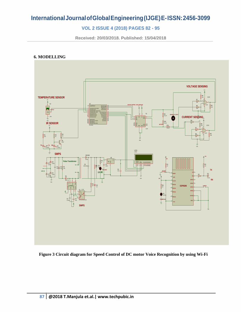
6. MODELLING
Figure 3 Circuit diagram for Speed Control of DC motor Voice Recognition by using Wi-Fi
RESET
ADC
CH_PD
GPIO16
GPIO14
GPIO12
GPIO13
VCC
TX
RX
GPIO4
GPIO5
GPIO0
GPIO2
GPIO15
GND
R110k
JUMPER
3V3
D1
S-4148
R2
1k
R33.3K
3V3
3V3
ESP8266
D2LED-RED
R410k
POWER LED
TX
RX
D11N4007
D21N4007
D31N4007
D41N4007
C110uf/450V
C2100uf
R1100k
D5
FR107
GND
GN
D5
I se
nse
3
RT
/CT
4
VfB
2
OU
T6
Vre
f8
CO
MP
1
Vi
7
C347uf/63v
C4100uf
6
4
4
1
2
U1
OPTOCOUPLER-NPN
R222k D6
12V
SR2100
BAS16
C51000uF/25V R3
47k
C61000uf
R41k
230V AC
Pulse Transformer
ULN3845BN
PC 817
12V DC
C31000uF
VI1
VO3
GN
D2
U5
7805
C4100n
AC INPUT
SMPS
27.0
3
1
VOUT2
U1
LM35
+5V
GND
TEMPERATURE SENSOR
OUTPUT
Q1BC547
R210k
D1LUMILED
R1220R
D2LUMILED
R310k
TX RX
VCC
IR SENSOR
3
2
1
411
U1:A
LM324R5100k
R7
100k
R8
100k
R6100k
VCC
GND
3
2
1
411
U1:A
LM324R5100k
R7
100k
R8
100k
R4
51kR6100k
VCC
GND
SENSING DC INPUT
VOLTAGE SENSING
CURRENT SENSING
SMPS
IN12
OUT13
OUT26
OUT311
OUT414
IN27
IN310
IN415
EN11
EN29
VS
8
VSS
16
GND GND
U1
L293D
GND
+5V+5V
MOTOR A
MOTOR CONTROL LOGIC FROM MC
R9PULLUP
R10PULLUP
R11
PULLUP
D7
14
D6
13
D5
12
D4
11
D3
10
D2
9D
18
D0
7
E6
RW
5R
S4
VS
S1
VD
D2
VE
E3
LCD1LM016L
RA0/AN0/ULPWU/C12IN0-2
RA1/AN1/C12IN1-3
RA2/AN2/VREF-/CVREF/C2IN+4
RA4/T0CKI/C1OUT6
RA5/AN4/SS/C2OUT7
RB0/AN12/INT21
RB1/AN10/P1C/C12IN3-22
RB2/AN8/P1B23
RA7/OSC1/CLKIN9
RA6/OSC2/CLKOUT10
RC0/T1OSO/T1CKI11
RC1/T1OSI/CCP212
RB7/ICSPDAT28
RB6/ICSPCLK27
RB5/AN13/T1G26
RB4/AN11/P1D25
RC7/RX/DT18
RC6/TX/CK17
RC5/SDO16
RC4/SDI/SDA15
RC3/SCK/SCL14
RC2/CCP1/P1A13
RA3/AN3/VREF+/C1IN+5
RB3/AN9/PGM/C12IN2-24
RE3/MCLR/VPP1
U2
PIC16F883
GND

88 @2018 T.Manjula et.al.| www.techpubic.in
International Journal of Global Engineering (IJGE) E- ISSN: 2456-3099
VOL 2 ISSUE 4 (2018) PAGES 82 - 95
Received: 20/03/2018. Published: 15/04/2018
7. SIMULATION SETUP
Figure 4 Motor forward condition
Figure 5 Motor reverse condition
B7
B6
B5
B4
TX
Tx
Rx
RX
B1
B0
E0
A0
A1
B2
B3
C0
C1
C2
A0
A2
A2
A1
B4
D7
14D
613
D5
12D
411
D3
10D
29
D1
8D
07
E6
RW5
RS
4
VS
S1
VD
D2
VE
E3
LCD1LM016L
GND
RE3/MCLR/VPP1
RA1/AN1/C12IN1-3
RA2/AN2/VREF-/CVREF/C2IN+4
RA4/T0CKI/C1OUT6
RA5/AN4/SS/C2OUT7
RB0/AN12/INT33
RB1/AN10/C12IN3-34
RB2/AN835
RA7/OSC1/CLKIN13
RA6/OSC2/CLKOUT14
RD5/P1B28
RD6/P1C29
RD7/P1D30
RC4/SDI/SDA23
RC5/SDO24
RC3/SCK/SCL18
RC2/P1A/CCP117
RC1/T1OSI/CCP216
RC0/T1OSO/T1CKI15
RB7/ICSPDAT40
RB6/ICSPCLK39
RB5/AN13/T1G38
RB4/AN1137
RD322
RD221
RD120
RD019
RC7/RX/DT26
RC6/TX/CK25
RE2/AN710
RE1/AN69
RE0/AN58
RA3/AN3/VREF+/C1IN+5
RD427
RB3/AN9/PGM/C12IN2-36
RA0/AN0/ULPWU/C12IN0-2
U3
PIC16F887
R210k
VDD
RXD
RTS
TXD
CTS
34%
RV2
1k
VDD
GND
V
8%
RV1
1k
VDD
GND
I
55.0
3
1
VOUT2
U1
LM35
GND
VDD
Q3BC547
VCC
RL35V 3.3V
B7
B6
B5
B4
TX
Tx
Rx
RX
B1
B0
E0
A0
A1
B2
B3
C0
C1
C2
A0
A2
A2
A1
B4
D714
D613
D512
D411
D310
D29
D18
D07
E6
RW5
RS4
VSS
1
VDD
2
VEE
3
LCD1LM016L
GND
RE3/MCLR/VPP1
RA1/AN1/C12IN1-3
RA2/AN2/VREF-/CVREF/C2IN+4
RA4/T0CKI/C1OUT6
RA5/AN4/SS/C2OUT7
RB0/AN12/INT33
RB1/AN10/C12IN3-34
RB2/AN835
RA7/OSC1/CLKIN13
RA6/OSC2/CLKOUT14
RD5/P1B28
RD6/P1C29
RD7/P1D30
RC4/SDI/SDA23
RC5/SDO24
RC3/SCK/SCL18
RC2/P1A/CCP117
RC1/T1OSI/CCP216
RC0/T1OSO/T1CKI15
RB7/ICSPDAT40
RB6/ICSPCLK39
RB5/AN13/T1G38
RB4/AN1137
RD322
RD221
RD120
RD019
RC7/RX/DT26
RC6/TX/CK25
RE2/AN710
RE1/AN69
RE0/AN58
RA3/AN3/VREF+/C1IN+5
RD427
RB3/AN9/PGM/C12IN2-36
RA0/AN0/ULPWU/C12IN0-2
U3
PIC16F887
R210k
VDD
RXD
RTS
TXD
CTS
34%
RV2
1k
VDD
GND
V
8%
RV1
1k
VDD
GND
I
55.0
3
1
VOUT2
U1
LM35
GND
VDD
Q3BC547
VCC
RL35V 3.3V
89 @2018 T.Manjula et.al.| www.techpubic.in
International Journal of Global Engineering (IJGE) E- ISSN: 2456-3099
VOL 2 ISSUE 4 (2018) PAGES 82 - 95
Received: 20/03/2018. Published: 15/04/2018
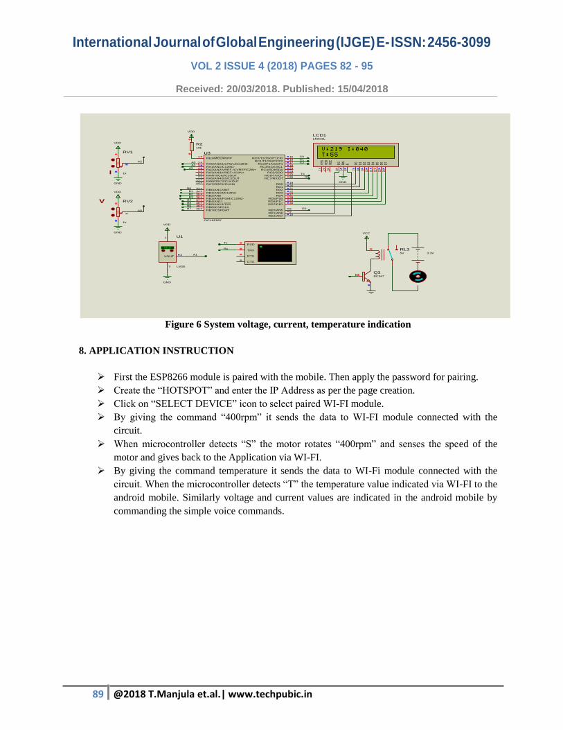
Figure 6 System voltage, current, temperature indication
8. APPLICATION INSTRUCTION
First the ESP8266 module is paired with the mobile. Then apply the password for pairing.
Create the “HOTSPOT” and enter the IP Address as per the page creation.
Click on “SELECT DEVICE” icon to select paired WI-FI module.
By giving the command “400rpm” it sends the data to WI-FI module connected with the
circuit.
When microcontroller detects “S” the motor rotates “400rpm” and senses the speed of the
motor and gives back to the Application via WI-FI.
By giving the command temperature it sends the data to WI-Fi module connected with the
circuit. When the microcontroller detects “T” the temperature value indicated via WI-FI to the
android mobile. Similarly voltage and current values are indicated in the android mobile by
commanding the simple voice commands.
B7
B6
B5
B4
TX
Tx
Rx
RX
B1
B0
E0
A0
A1
B2
B3
C0
C1
C2
A0
A2
A2
A1
B4
D7
14D
613
D5
12D
411
D3
10D
29
D1
8D
07
E6
RW5
RS
4
VSS
1
VDD
2
VEE
3
LCD1LM016L
GND
RE3/MCLR/VPP1
RA1/AN1/C12IN1-3
RA2/AN2/VREF-/CVREF/C2IN+4
RA4/T0CKI/C1OUT6
RA5/AN4/SS/C2OUT7
RB0/AN12/INT33
RB1/AN10/C12IN3-34
RB2/AN835
RA7/OSC1/CLKIN13
RA6/OSC2/CLKOUT14
RD5/P1B28
RD6/P1C29
RD7/P1D30
RC4/SDI/SDA23
RC5/SDO24
RC3/SCK/SCL18
RC2/P1A/CCP117
RC1/T1OSI/CCP216
RC0/T1OSO/T1CKI15
RB7/ICSPDAT40
RB6/ICSPCLK39
RB5/AN13/T1G38
RB4/AN1137
RD322
RD221
RD120
RD019
RC7/RX/DT26
RC6/TX/CK25
RE2/AN710
RE1/AN69
RE0/AN58
RA3/AN3/VREF+/C1IN+5
RD427
RB3/AN9/PGM/C12IN2-36
RA0/AN0/ULPWU/C12IN0-2
U3
PIC16F887
R210k
VDD
RXD
RTS
TXD
CTS
44%
RV2
1k
VDD
GND
V
8%
RV1
1k
VDD
GND
I
55.0
3
1
VOUT2
U1
LM35
GND
VDD
Q3BC547
VCC
RL35V 3.3V
90 @2018 T.Manjula et.al.| www.techpubic.in
International Journal of Global Engineering (IJGE) E- ISSN: 2456-3099
VOL 2 ISSUE 4 (2018) PAGES 82 - 95
Received: 20/03/2018. Published: 15/04/2018
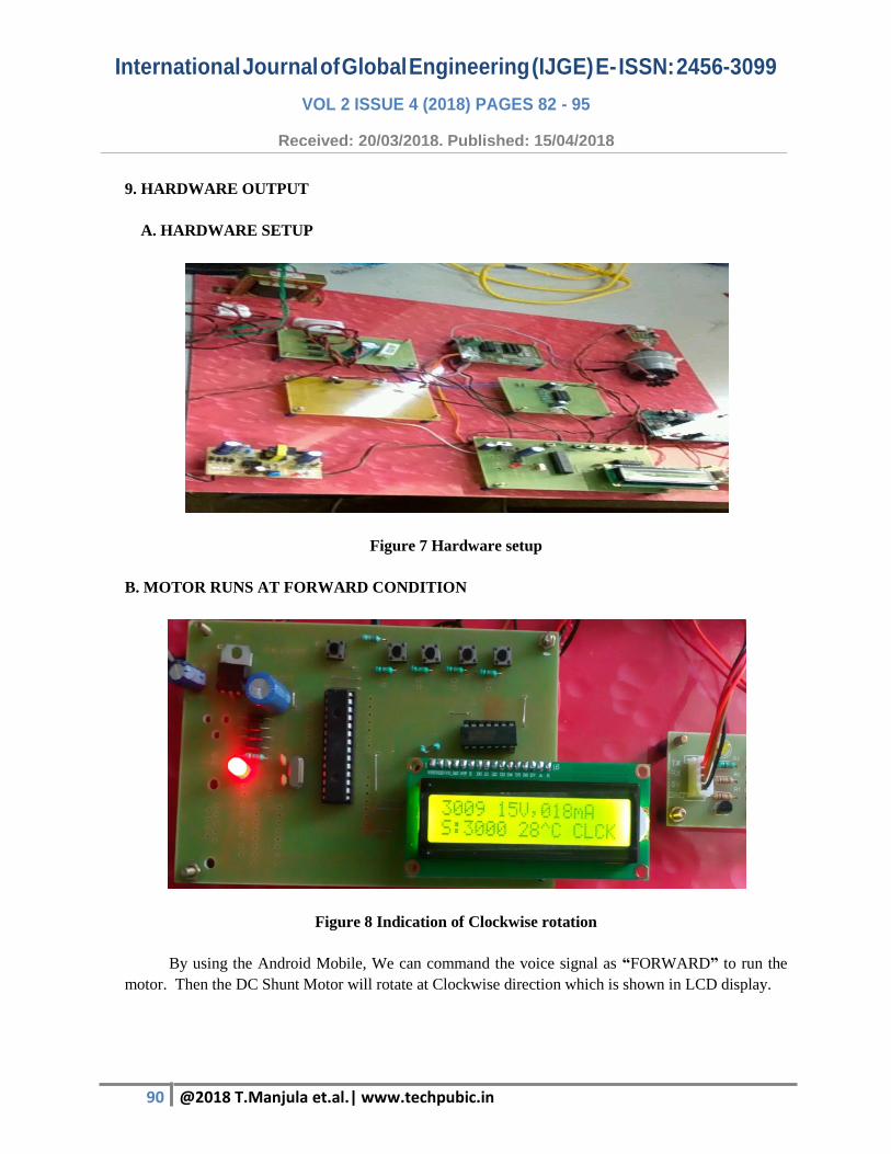
9. HARDWARE OUTPUT
A. HARDWARE SETUP
Figure 7 Hardware setup
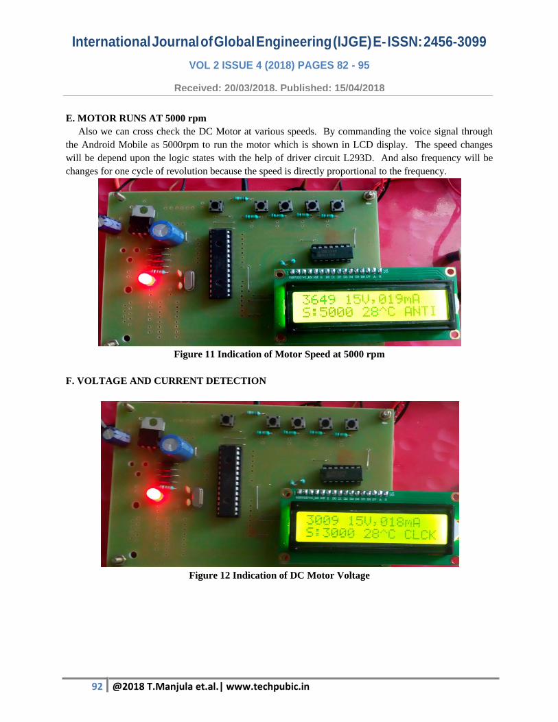
B. MOTOR RUNS AT FORWARD CONDITION
Figure 8 Indication of Clockwise rotation
By using the Android Mobile, We can command the voice signal as “FORWARD” to run the
motor. Then the DC Shunt Motor will rotate at Clockwise direction which is shown in LCD display.

91 @2018 T.Manjula et.al.| www.techpubic.in
International Journal of Global Engineering (IJGE) E- ISSN: 2456-3099
VOL 2 ISSUE 4 (2018) PAGES 82 - 95
Received: 20/03/2018. Published: 15/04/2018
C. MOTOR RUNS AT REVERSE CONDITIION
Figure 9 Indication of Anti-clockwise direction
The same way by commanding the voice signal as “REVERSE” to run the motor. Then the DC
Shunt Motor will rotate at Anti-clockwise direction which is shown in LCD display.
D. MOTOR RUNS AT 4000 rpm
Figure 10 Indication of Motor speed at 4000 rpm
Speed control is the major process of this project. Hence commanding the voice as 4000rpm through
Wi-Fi by using the Android Mobile the motor will run at given condition. In this project the starting
range of setting speed is 300rpm upto 6000rpm.
92 @2018 T.Manjula et.al.| www.techpubic.in
International Journal of Global Engineering (IJGE) E- ISSN: 2456-3099
VOL 2 ISSUE 4 (2018) PAGES 82 - 95
Received: 20/03/2018. Published: 15/04/2018
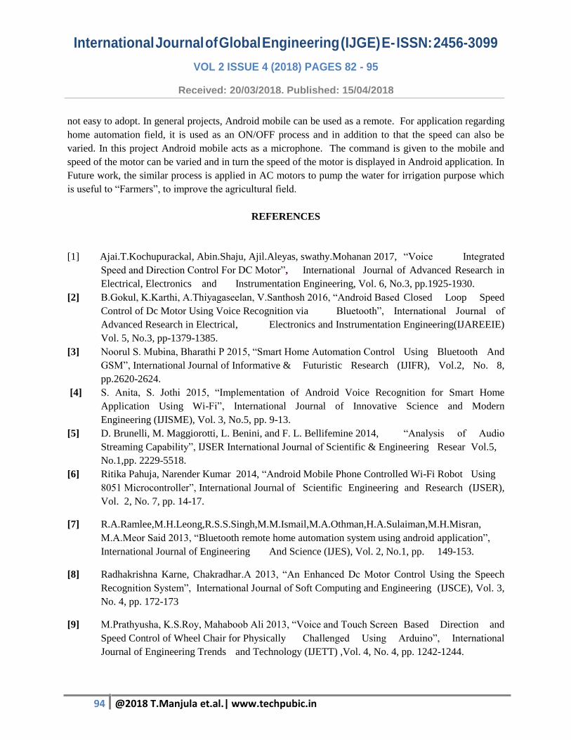
E. MOTOR RUNS AT 5000 rpm
Also we can cross check the DC Motor at various speeds. By commanding the voice signal through
the Android Mobile as 5000rpm to run the motor which is shown in LCD display. The speed changes
will be depend upon the logic states with the help of driver circuit L293D. And also frequency will be
changes for one cycle of revolution because the speed is directly proportional to the frequency.
Figure 11 Indication of Motor Speed at 5000 rpm
F. VOLTAGE AND CURRENT DETECTION
Figure 12 Indication of DC Motor Voltage

93 @2018 T.Manjula et.al.| www.techpubic.in
International Journal of Global Engineering (IJGE) E- ISSN: 2456-3099
VOL 2 ISSUE 4 (2018) PAGES 82 - 95
Received: 20/03/2018. Published: 15/04/2018
Figure 13 Indication of DC Motor Current
Figure 12 shows the DC motor voltage by voltage divider rule is 15V and Figure 13 shows the DC motor
current by current division rule is 19mA.
G. TEMPERATURE SENSOR
Figure 14 Indication of temperature
10. CONCLUSION
In previous system, the DC motor speed will be controlled using various techniques. But the speed
control will not be easy. The system will run the DC motor at fixed speed, to change the speed complete
setup will be altered. There is no advanced system to monitor the speed of the DC motor. The speed
value cannot be changed and load is not efficient. Cannot operate in explosive and hazard conditions and
94 @2018 T.Manjula et.al.| www.techpubic.in
International Journal of Global Engineering (IJGE) E- ISSN: 2456-3099
VOL 2 ISSUE 4 (2018) PAGES 82 - 95
Received: 20/03/2018. Published: 15/04/2018
not easy to adopt. In general projects, Android mobile can be used as a remote. For application regarding
home automation field, it is used as an ON/OFF process and in addition to that the speed can also be
varied. In this project Android mobile acts as a microphone. The command is given to the mobile and
speed of the motor can be varied and in turn the speed of the motor is displayed in Android application. In
Future work, the similar process is applied in AC motors to pump the water for irrigation purpose which
is useful to “Farmers”, to improve the agricultural field.
REFERENCES
[1] Ajai.T.Kochupurackal, Abin.Shaju, Ajil.Aleyas, swathy.Mohanan 2017, “Voice Integrated
Speed and Direction Control For DC Motor”, International Journal of Advanced Research in
Electrical, Electronics and Instrumentation Engineering, Vol. 6, No.3, pp.1925-1930.
[2] B.Gokul, K.Karthi, A.Thiyagaseelan, V.Santhosh 2016, “Android Based Closed Loop Speed
Control of Dc Motor Using Voice Recognition via Bluetooth”, International Journal of
Advanced Research in Electrical, Electronics and Instrumentation Engineering(IJAREEIE)
Vol. 5, No.3, pp-1379-1385.
[3] Noorul S. Mubina, Bharathi P 2015, “Smart Home Automation Control Using Bluetooth And
GSM”, International Journal of Informative & Futuristic Research (IJIFR), Vol.2, No. 8,
pp.2620-2624.
[4] S. Anita, S. Jothi 2015, “Implementation of Android Voice Recognition for Smart Home
Application Using Wi-Fi”, International Journal of Innovative Science and Modern
Engineering (IJISME), Vol. 3, No.5, pp. 9-13.
[5] D. Brunelli, M. Maggiorotti, L. Benini, and F. L. Bellifemine 2014, “Analysis of Audio
Streaming Capability”, IJSER International Journal of Scientific & Engineering Resear Vol.5,
No.1,pp. 2229-5518.
[6] Ritika Pahuja, Narender Kumar 2014, “Android Mobile Phone Controlled Wi-Fi Robot Using
8051 Microcontroller”, International Journal of Scientific Engineering and Research (IJSER),
Vol. 2, No. 7, pp. 14-17.
[7] R.A.Ramlee,M.H.Leong,R.S.S.Singh,M.M.Ismail,M.A.Othman,H.A.Sulaiman,M.H.Misran,
M.A.Meor Said 2013, “Bluetooth remote home automation system using android application”,
International Journal of Engineering And Science (IJES), Vol. 2, No.1, pp. 149-153.
[8] Radhakrishna Karne, Chakradhar.A 2013, “An Enhanced Dc Motor Control Using the Speech
Recognition System”, International Journal of Soft Computing and Engineering (IJSCE), Vol. 3,
No. 4, pp. 172-173
[9] M.Prathyusha, K.S.Roy, Mahaboob Ali 2013, “Voice and Touch Screen Based Direction and
Speed Control of Wheel Chair for Physically Challenged Using Arduino”, International
Journal of Engineering Trends and Technology (IJETT) ,Vol. 4, No. 4, pp. 1242-1244.
95 @2018 T.Manjula et.al.| www.techpubic.in
International Journal of Global Engineering (IJGE) E- ISSN: 2456-3099
VOL 2 ISSUE 4 (2018) PAGES 82 - 95
Received: 20/03/2018. Published: 15/04/2018
[10] Sabedin A. Meha, Besnik Haziri, Loreta N. Gashi 2011,“Controlling DC motor speed using
PWM from C# Windows application”, 15th International Research and Expert Conference,
"Trends in the Development of Machinery and Associated Technology”, Vol. 2, No.1, pp.195-
198.
[11] Sandeep Kumar and Mohammed A Qadeer 2009, “Universal Digital Device Automation and
Control”, in IEEE, Vol.3, No. 4, pp. 490-494.
[12] Wijetunge S.P., Wijetunge U.S., Peiris G.R.V, Aluthgedara C.S. and Samarasinghe A.T.L.K.
2008, “Design and Implementation of a Bluetooth based General Purpose Controlling
Module”, in IEEE, Vol.5, No. 2, pp. 206-211g Bluetooth And G