Andrew Au - Simon Fraser Universitywhitmore/courses/ensc305/projects/… · · 2011-01-07based on...
52
i November 14 th , 2010 Dr. Andrew Rawicz School of Engineering Science, SFU 8888 University Drive Burnaby, British Columbia V5A 1S6 Re: ENSC440 Design Specification for a Facial and Speech Identification System (FASIS) Dear Dr. Rawicz: The attached document, Design Specification for a Facial and Speech Identification System for Nokia Devices, outlines the technical design goals and system behavior of our project for ENSC440/ ENSC305. The purpose of this project is to implement a security system that provides secured mobile log-in based on a combination successful facial match and speech recognition of the user. The project, supported partially by Nokia by providing us with the device, will become a prototype system that can provide one of the teams at Nokia Canada with expertise and insight for any future implementation. This design specification document will provide technical details of the three components: the mobile application, the communication board, and the server which provides the facial matching algorithm, and stores the database of users’ facial images. The parts and methods will be discussed in detail, which are specific only to the proof-of-concept design. The test plan for each component, as well as the integrated system, will be provided in this document as well. Ztitch Solutions consists of three motivated fifth-year engineering students: Andrew Au (computer engineering), George Liao (system engineering), and Ching-Hsin Chen (computer engineering). By harvesting our skills and knowledge gained through our undergraduate careers and from industrial co-op experiences, we will be tackling this problem of mobile security and bringing life to this project. If you have any question or concern about our design specification document, feel free to contact me by phone (778-322-7928) or by e-mail ([email protected]). Sincerely, Andrew Au Fifth-year Computer Engineering Student Enclosure: Design Specification for a Facial and Speech Identification System for Nokia Devices
Transcript of Andrew Au - Simon Fraser Universitywhitmore/courses/ensc305/projects/… · · 2011-01-07based on...

i
November 14th, 2010
Dr. Andrew Rawicz
School of Engineering Science, SFU
8888 University Drive
Burnaby, British Columbia
V5A 1S6
Re: ENSC440 Design Specification for a Facial and Speech Identification System (FASIS)
Dear Dr. Rawicz:
The attached document, Design Specification for a Facial and Speech Identification System for Nokia Devices, outlines the technical design goals and system behavior of our project for ENSC440/ ENSC305. The purpose of this project is to implement a security system that provides secured mobile log-in based on a combination successful facial match and speech recognition of the user. The project, supported partially by Nokia by providing us with the device, will become a prototype system that can provide one of the teams at Nokia Canada with expertise and insight for any future implementation.
This design specification document will provide technical details of the three components: the mobile application, the communication board, and the server which provides the facial matching algorithm, and stores the database of users’ facial images. The parts and methods will be discussed in detail, which are specific only to the proof-of-concept design. The test plan for each component, as well as the integrated system, will be provided in this document as well.
Ztitch Solutions consists of three motivated fifth-year engineering students: Andrew Au (computer engineering), George Liao (system engineering), and Ching-Hsin Chen (computer engineering). By harvesting our skills and knowledge gained through our undergraduate careers and from industrial co-op experiences, we will be tackling this problem of mobile security and bringing life to this project. If you have any question or concern about our design specification document, feel free to contact me by phone (778-322-7928) or by e-mail ([email protected]).
Sincerely,
Andrew Au Fifth-year Computer Engineering Student
Enclosure: Design Specification for a Facial and Speech Identification System for Nokia Devices

i
Design Specification for a
Facial and Speech Identification System (FASIS)
for Nokia Devices
Project Team: Andrew Au
George Liao
Ching-Hsin Chen
Contact Person: Andrew Au
Submitted to: Dr. Andrew Rawicz – ENSC 440
Michael Sjoerdsma – ENSC 305
School of Engineering Science
Simon Fraser University
Issued date: November 14th, 2010
Revision: 6.2

ii
Executive Summary
This document will describe the Facial Identification System (FASIS) in detail as to its
design specification. The system can be divided into four main physical components,
which are the mobile device, the hardware transceiver, the microcontroller, and the PC
server. These components will be introduced along with their design details for the
proof-of-concept system. Thus, the I and II requirements from the functional
specification document will be discussed and used to guide through the development
process of the system.
The phone is a Nokia N96 running the Symbian S60 V3.2 operating system. The
development platforms available are Qt, Java ME, Symbian C++, Open C/C++, and
Python. The objective is to detect when the user wants to access secured data on the
phone, and then trigger FASIS to prompt the front-facing camera. In order for the
phone to be controlled remotely, i.e. to lock and unlock the phone via the server
(discussed later), the phone must house the software interface allowing this.
The hardware communication board is attached to the N96 device through the side of
the device. This hardware board is very simplistic, with the heart of it being a Maxim
MAX3222E EAP0647 chip which is a communications interface IC that has low power
consumption, high data rate, and enhanced electrostatic-discharge protection. The low
power consumption feature is important because we may want to power the entire
system using only the original battery source of the phone. This board will essentially
allow us to relay some information to the server, such as the user image or encrypted
key-codes for locking and unlocking the device. The microcontroller is built using the
Parallax education board kit, and will be wired to some buttons of the phone. This
essentially allows us to control the phone from the PC, though at a very limited level.

iii
The most important component of FASIS is the server, simulated in this proof-of-
concept by the PC, which provides the facial detection program and the facial matching
algorithm among other services required by FASIS. It should be noted that the facial
detection program is not the same as the facial identification program, because the
former is an algorithm which tries to find the location of the user’s face by sampling the
bitmap color information, while the latter is an algorithm which tries to determine
whether a face matches the one stored in the database. The facial recognition algorithm
used by Ztitch Solutions in this system is the Eigenface method.
This document will discuss the design choices, the processes, and the flow charts of
each of the component mentioned above. A test plan for each of the component and the
integrated system will be provided as well. It is expected that the final revision of the
proof-of-concept system can be demonstrated by the first week of December.
iv
List of Figures Figure 1. High-level proof-of-concept system flowchart................................................. 4 Figure 2. Logging into an HTTPS, such as PayPal............................................................ 5 Figure 3. Procedures for face blob localization.................................................................. 8 Figure 4. The process of face detection using skin color.................................................. 9 Figure 5. Some Eigenfaces from the AT&T Lab................................................................. 13 Figure 6. Eigenfeatures as a complement to Eigenfaces................................................... 14 Figure 7. High level functioning principle of the Eigenface method............................. 16 Figure 8. An overview of the Speech API........................................................................... 22 Figure 9. Diagram of a generic 4x4 keypad's circuit......................................................... 24 Figure 10. Image of the Parallax BOE without the MCU................................................. 25 Figure 11. The BOE schematics............................................................................................ 29 Figure 12. Circuit and coding for a light sensor using the Parallax kit.......................... 30 Figure 13. RS232 transmitters must swing at least +/- 5V............................................... 32 Figure 14. RS232 application circuit for 3.6V using the MAX3222 chip......................... 33 Figure 15. Picture of the FASIS hardware inside a customized plastic case................... 34 Figure 16. The FASIS concept as a portable module............................................................. 35
List of Tables Table 1: High-level proof-of-concept system flowchart................................................... 15 Table 2: Budget Summary..................................................................................................... 36
Glossary 2G Second-Generation Wireless 3G Third-Generation Wireless BOE Board of Education HSPA High Speed Packet Access HTI Harmonized Test Interface HTTPS Hypertext Transfer Protocol Secure
ISO International Organization for Standardization KB Kilobyte (1024 bytes) FASIS Facial and Speech Identification System MCU Microcontroller Unit OEM Original Equipment Manufacturer PC Personal Computer RS232 Recommended Serial 232 SDK Software Development Kit UI User Interface USB Universal Serial Bus WEEE Waste Electrical and Electronic Equipment Wi-Fi Wireless Fidelity

v
Table of Contents
Executive Summary…........................................................................................................ ii
List of Figures….................................................................................................................. iv
List of Tables……………………………………………………………………………... iv
Glossary…............................................................................................................................ iv
1. Introduction …................................................................................................................ 1
1.1. Scope ….......................................................................................................................... 2
1.2. Intended Audience....................................................................................................... 2
2. The FASIS System ……................................................................................................. 2
2.1. Development Stages …................................................................................................ 3
2.1.1. Client-Server Communication................................................................................. 3
2.1.2. Speech Recognition ….............................................................................................. 3
2.1.3. Facial Recognition …................................................................................................ 3
2.1.4. Phone Software …..................................................................................................... 4
2.2. System Overview…. …................................................................................................ 4
3. Face Localization …........................................................................................................ 6
3.1. Overview of Facial Localization …............................................................................ 6
3.1.1. Face Tracking Based on Depth Information…...................................................... 7
3.1.2. Face Blob Localization……………………………………………………………... 8
3.1.3. Skin Color Based Face Detection…………………………………………………. 8
3.1.4. Choosing the Localization Method………………………………………………. 9
3.2. Implementing Skin Color Based Face Detection…….............................................. 10
4. Overview of Facial Recognition ………….................................................................. 12
4.1. Comparison of Different Facial Recognition Methods…………………………… 12
4.1.1. Eigenface……………………………………………………………………………. 12
4.1.2. Eigenfeatures……………………………………………………………………….. 14
4.1.3. Fisherface…………………………………………………………………………… 14
4.1.4. Eigenface vs. Fisherface Summary……………………………………………….. 15
vi
4.2. Implementation of Eigenface……………………………………………………….. 16
4.2.1. Calculating the Eigenfaces………………………………………………………... 16
4.2.2. Eigenvectors and eigenvalues…………………………………………………….. 18
4.2.3. Matching the Faces………………………………………………………………… 18
5. Secondary Preventative Measures…………………………………………………... 19
5.1. Solutions for Secondary Preventatives Measures………………………………… 19
5.1.1. Log-in using Password……………………………………………………………. 19
5.1.2. Fingerprint Identification…………………………………………………………. 20
5.1.3. Eye Iris Identification……………………………………………………………… 20
5.1.4. Speech Recognition………………………………………………………………... 21
5.2. Implementation of Speech Recognition……………………………………………. 22
6. Controller Module…………………………………………………………………….. 23
6.1. The Cell Phone Push Buttons……………………………………………………….. 23
6.2. Choosing a Microcontroller Module……………………………………………….. 25
6.3. Parallax Board of Education………………………………………………………… 25
6.3.1. Light Sensor Circuit using the BOE……………………………………………… 30
7. Client-Server Communication………………………………………………….…… 30
7.1. Transceiver Module………………………………………………………………….. 31
7.1.1. RS232 Transceiver………………………………………………………………….. 31
7.1.2. Power Supplies…………………………………………………………………….. 32
7.2. Minimizing Data Transfer…………………………………………………………... 33
8. Proof-of-Concept Integrated Hardware...................................................................... 34
9. System Test Plan………………………………………………………………………. 36
9.1. Unit Test………………………………………………………………………………. 36
9.2. Automated Tests……………………………………………………………………... 39
9.3. Integrated Test and Simulation…………………………………………………….. 40
10. References…………………………………………………..………………………… 42
Appendix…………………………………………………......…………………………… 44

1
1. Introduction
The Facial Identification System (FASIS) enables added security to the modern smart
phone by recognizing users with matching facial features and knowledge to a voice-
based password to access certain security sensitive features of the phone, while locking
unrecognized users out. FASIS consists of four main sub-systems: the microcontroller
which allows the PC to control the phone, a transceiver module to relay data back to the
PC, a facial localization and recognition system, and a speech recognition system.
This system comes in response to the growing need of enhanced security for mobile
phone users as more personal and confidential information are stored within the device.
This design specification document, together with the functional specification
documentation [1], will act as a major guideline for the development of the FASIS
proof-of-concept system.
Development of FASIS can be divided into four phases that are independent from each
other:
1) Development of the microcontroller and transceiver wired to the phone such
that it will allow it to be controlled (remotely) by the PC
2) Integration of the speech recognition software to recognize a user's spoken
password. This stage should be fairly simple as there are many open sources,
such as Microsoft's Speech SDK.
3) Development of the facial localization and facial recognition algorithm using
C# and MATLAB, respectively.
4) Development of the FASIS application on the phone
2
1.1. Scope
This document provides the design specification for the functional specification
document [1]. This document specifies the implementation of the functional
requirements, and outlines the design considerations. The document will mostly apply
only for the proof-of-concept system, therefore only the functional requirements
marked I and II will be considered. However, some end product requirements will be
considered to allow Nokia to the transformation of this proof-of-concept system into a
potentially commercialized product.
1.2. Intended Audience
This document is intended for the engineers at Ztitch Solutions to refer to, and is used
extensively for the development of the proof-of-concept system. The purpose is to
provide a unified vision for the team and to optimize development work and design
choices that will be involved with this project. By referring to this document, integration
of the sub-systems can be streamlined while minimizing conflicts. Furthermore, the test
plans must be followed thoroughly by all members of the team.
2. The FASIS System
This section provides a system overview of FASIS as a whole and will discuss the
following: the development stages, a flowchart of the system and its functional
operations. The subsequent sections will contain much more in-depth looks at each
component and its design - acknowledging the justifications of design choices. It should
be clear enough as to what features or components will be included in the proof-of-
concept system and which ones will not.

3
2.1. Development Stages
Development of the system can be broken into four stages, which are described in the
following subsections.
2.1.1. Client-Server Communication
The first stage is development of the link way between the device and the PC (server).
Since broadcasting a real HSPA signal would not be feasible in the scope of this project,
we will be using Bluetooth, USB, or simply a RS232 serial cable to simulate the over-the-
air (OTA) connection.
2.1.2. Speech Recognition
The second stage is the implementation of speech recognition. In the proof-of-concept
system, FASIS will attempt to verify that the user speaks the correct password to the
microphone (the owner of the device will initially configure this voice-based password).
For speech recognition, there are many open source libraries available; including
Microsoft's established Speech Recognition SDK5.1 as found in [11], and in the proof-of-
concept FASIS, we will not try to uniquely identify the user based on voice patterns, but
rather, we will try to verify that the spoken keyword is correct only (since speech
pattern recognition is a very in-depth subject on its own and none of the members in the
team have expertise in this particular area).
2.1.3. Facial Recognition
The third stage is the development of the facial detection algorithm on the PC which
simulates the service provided by the network server, which acts as the middleman that
grants or denies the user access to the service. The PC is constantly on standby for
receiving a request, which in this case, is a small bitmap stream. A unique key is
4
Device captures user’s face using the front-facing camera
returned if access is granted, or an instruction to lock the user out will be returned if
access is denied.
2.1.4. Phone Software
The fourth stage is the development of the application on the phone which sends the
bitmap stream and receives the key. Since the amount of data being transmitted goes up
with cost, we want to minimize the amount of data being transmitted. The bitmap
image will be encoded and transformed to grayscale (total size would be 2 to 4-kB in
size) and the returned key is 128-bit in size.
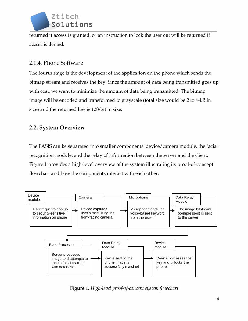
2.2. System Overview
The FASIS can be separated into smaller components: device/camera module, the facial
recognition module, and the relay of information between the server and the client.
Figure 1 provides a high-level overview of the system illustrating its proof-of-concept
flowchart and how the components interact with each other.
Figure 1. High-level proof-of-concept system flowchart
User requests access to security-sensitive information on phone
Microphone captures voice-based keyword from the user
The image bitstream (compressed) is sent to the server
Server processes image and attempts to match facial features with database
Key is sent to the phone if face is successfully matched
Device processes the key and unlocks the phone
Device module
Microphone
Data Relay Module
Face Processor Data Relay Module
Device module
Camera
5
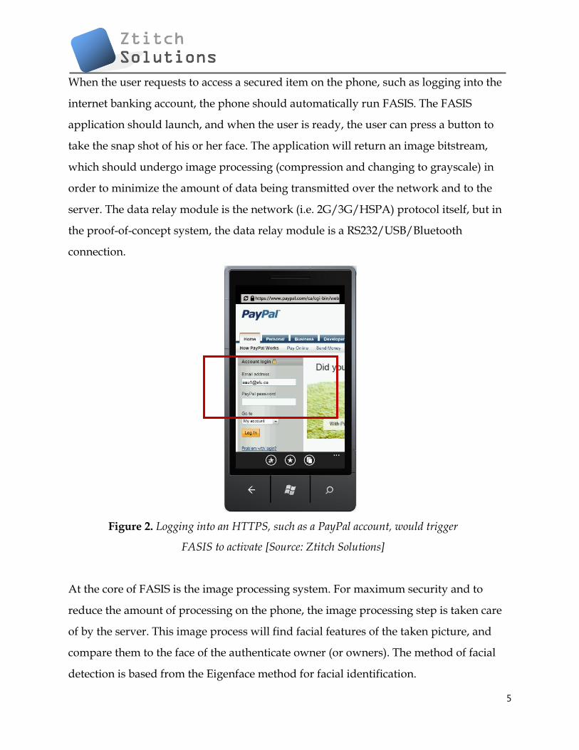
When the user requests to access a secured item on the phone, such as logging into the
internet banking account, the phone should automatically run FASIS. The FASIS
application should launch, and when the user is ready, the user can press a button to
take the snap shot of his or her face. The application will return an image bitstream,
which should undergo image processing (compression and changing to grayscale) in
order to minimize the amount of data being transmitted over the network and to the
server. The data relay module is the network (i.e. 2G/3G/HSPA) protocol itself, but in
the proof-of-concept system, the data relay module is a RS232/USB/Bluetooth
connection.
Figure 2. Logging into an HTTPS, such as a PayPal account, would trigger
FASIS to activate [Source: Ztitch Solutions]
At the core of FASIS is the image processing system. For maximum security and to
reduce the amount of processing on the phone, the image processing step is taken care
of by the server. This image process will find facial features of the taken picture, and
compare them to the face of the authenticate owner (or owners). The method of facial
detection is based from the Eigenface method for facial identification.

6
Once the server is able to successfully match the user’s face with the database, a
standard 128-bit unique key is sent back to the client to unlock it. If the server is unable
to match the user’s face with the database, an instruction to deny access will be relayed
back to the device. Since facial identification is not 100% reliable, the device will not be
completely locked out, and there should be a total of three retries to access the secured
item. Under all circumstances, normal functions of the phone will be retained
(including the ability to dial and receive calls) – only the secured items will be locked
out from the user.
Due to limitation of time and resources, the proof-of-concept system (prototype) will
exclude several features of the production system. However, the overall operation
remains as described above.
3. Face Localization
Facial localization is the tracking of the human face, or computing the location of the
face in an image. There are a few numbers of established methods to detect the location
of the face in an image; for example, some algorithms use multiple cameras to track a
3D face based on depth information, some methods track for a set of facial features
based on interest points, and some very simple methods tracks the skin color. The next
section will discuss the various facial localization techniques and it will come to sense
as to which technique will be most suitable for our project.
3.1. Overview of Facial Localization
In the realm of computer vision, the human face is an extremely linked 3D model
because of the lacking of variation in the skin surface. There are not many unique
features that can be identified, and the problem is further amplified when the resolution

7
of the camera is low, as in the case with our project (the front facing camera has a
resolution of 320x240 only). Although facial features such as the eyes and mouth
different from the skin in terms of color, the hairless skin regions dominate the area,
and different lighting variations accentuates the contour of the face structure.
3.1.1. Face Tracking Based on Depth Information
The paper, "A simple 3D face tracking method based on depth information" presented
at the international conference on machine learning and cybernetics [3] describes a
simplified method of face tracking based on depth information. The following is its
abstract:
'Most existing 3D face tracking methods employ multiple cameras and all
cameras need to be calibrated first before tracking. The complexity of these
methods restricts the applications of them. This paper presents a new simple face
tracking method which is based on a stereo vision camera system. All cameras in
this stereo vision camera system are pre-calibrated and the system can provide
accurate depth information of the scene. The proposed tracking method adopts
KLT and template matching to track 2D facial features. Then the stereo vision
camera system is used to obtain corresponding depth information of these
features. In order to achieve robust tracking, some spatial constraints of these
features are employed. Experiment results indicate that the proposed method
can achieve robust and accurate 3D face tracking.' [3]
While the method is robust and possibly very accurate, it works with multiple cameras,
and the cell phone is equipped with only one front facing camera; therefore, this
method of facial localization is out of the question. However, it is noteworthy that
researches such as these lead to the prospect that future mobile devices should come
equipped with multiple front facing cameras.

8
3.1.2. Face Blob Localization
One method, called Face Blob Localization, proposes that the face be considered as a
blob or a region with a certain amount of contour enclose. The face and the head behave
as blobs or symmetric enclosures surrounding a center point. The method operates on
edge maps so that it can locate the blob regardless of the blob's lighting and shadows
within the boundaries of the edge. The current drawback is that non-facial structures,
such as an over-shaped object in the background, could also trigger the interest map.
The author [2] begins with an image assumed to contain people, and then generate an
intensity image pyramid (figure 3a) and a corresponding edge map pyramid (figure 3b).
The multi-scale interest detection operation using annular sampling regions provides us
with a blob detection pyramid as displayed in figure 3c.
(a) (b) (c)
Figure 3. Procedure for face blob localization
3.1.3. Skin Color Based Face Detection
Many face detection methods propose using skin color as a feature to track. The
argument for this method is that color processing is much quicker than processing any
other facial feature. Furthermore, treating the facial region as a color blob makes it
9
invariant to rotation, which makes it very robust. Examples of such methods can be
found in [4] and [5].
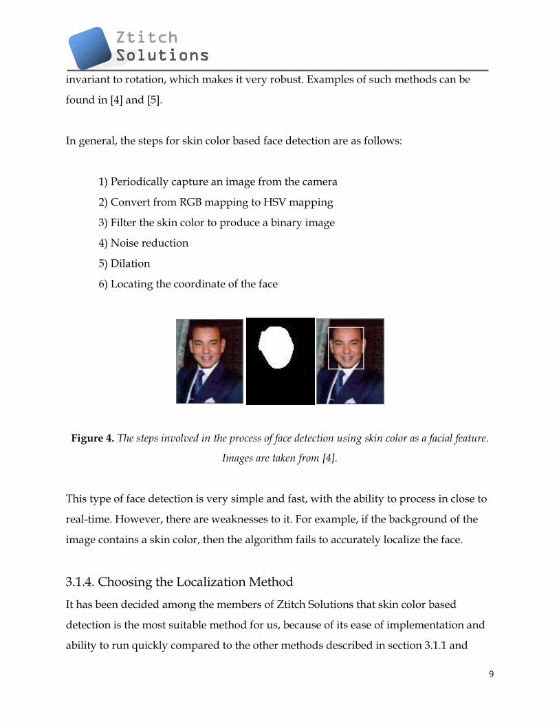
In general, the steps for skin color based face detection are as follows:
1) Periodically capture an image from the camera
2) Convert from RGB mapping to HSV mapping
3) Filter the skin color to produce a binary image
4) Noise reduction
5) Dilation
6) Locating the coordinate of the face
Figure 4. The steps involved in the process of face detection using skin color as a facial feature.
Images are taken from [4].
This type of face detection is very simple and fast, with the ability to process in close to
real-time. However, there are weaknesses to it. For example, if the background of the
image contains a skin color, then the algorithm fails to accurately localize the face.
3.1.4. Choosing the Localization Method
It has been decided among the members of Ztitch Solutions that skin color based
detection is the most suitable method for us, because of its ease of implementation and
ability to run quickly compared to the other methods described in section 3.1.1 and

10
3.1.2. However, we will also incorporate some of the ideas from section 3.1.2 into our
method, in particular, face blob localization. This is the dilation stage discussed in the
next section which outlines our implementation.
3.2. Implementing Skin Color Based Face Detection
The how-to steps for implementation that runs in real-time are as follows. The reader is
assumed to have some prior knowledge of object oriented programming:
1) Periodically capture an image from the camera
Initialize the device as a new instance of an object, and then set this object as the
source of a Video Element (the class name depends on the framework we are
using. In Visual Basic, it is called a VideoBrush).
Initialize an asynchronous timer such that it will periodically capture an image
from the Video Element. For example, set the timer that ticks every 50
milliseconds, and during each tick, grab a frame from Video Element which will
be used for the image processing (step 2). It is asynchronous because it is not
synchronized with the main UI thread, and must tick every 50 milliseconds
regardless of any other processes to ensure predictable performance. (In Visual
Basic, such a timer is called a DispatcherTimer).
2) Convert from RGB mapping to HSV mapping
With the image frame at hand, initialize it as the source of a bitmap. The bitmap
provides us with the pixel color information that we need. The color information
is represented in the traditional Red Green Blue format (RGB). Each color (Red,

11
Green, or Blue) is defined by a value that ranges from 0 to 255. In Visual Basic,
the bitmap class is called WriteableBitmap.
We transform the RGB mapping to the HSV (Hue, Saturation, Value) mapping
which allows us to define color based on Hue (color from 0° to 360°) and
Brightness. This allows us to define a skin color that is more invariant to different
lighting conditions by setting different thresholds for brightness.
3) Filter the skin color to produce a binary image
Define the thresholds such that the range of colors between the thresholds
matches the user's skin color. Testing will need to be done to confirm the best
threshold values.
Search all pixels in the bitmap and convert the pixels that fall within the
thresholds to white pixels, leaving the non-matching pixels black (zero value)
4) Noise reduction
The noise reduction stage should filter out noise pixels. Usually, there will be
noise pixels scattered about the image which results from image noise or
background objects that have its color fall within the threshold range
For each pixel, we check if nearby pixels are zeros. If yes, then the current pixel
should be eliminated to zero as well.
5) Dilation
The noise reduction of the previous stage inevitably causes the image to shrink.
We now do a reverse of the previous stage. Iteratively check each pixel to see
whether or one more nearby pixels are white. If yes, then set the current pixel to
white as well.
12
6) Locating the coordinate of the face
With a binary image, estimating the coordinate of the center face is easy. First,
add up all the white (non-zero) pixels of each row. Now, you have an array with
each value of the array corresponding to the sum of white pixels across each row.
The nth element in the array with largest value corresponds to your desired y-
coordinate.
Similarly, add up all the white (non-zero) pixels of each column. Now, you have
an array with each value in the array corresponding to the sum of white pixels in
each column. The nth element in the array with largest value corresponds to your
desired x-coordinate.
4. Overview of Facial Recognition
There are currently at least five different methods for facial matching: eigenfeatures, the
Hidden Markov model, the neuronal motivated dynamic link matching, Eigenface, and
Fisherface. They all have their advantages and disadvantages, but all share the same
characteristic which is that they turn the human face into a mathematical space.
4.1. Comparison of Different Facial Recognition Methods
In this section, we will detail the five methods of facial recognition listed previously,
and in the next section (4.2.), we come to conclusion as to which method we should use
for the proof-of-concept FASIS.
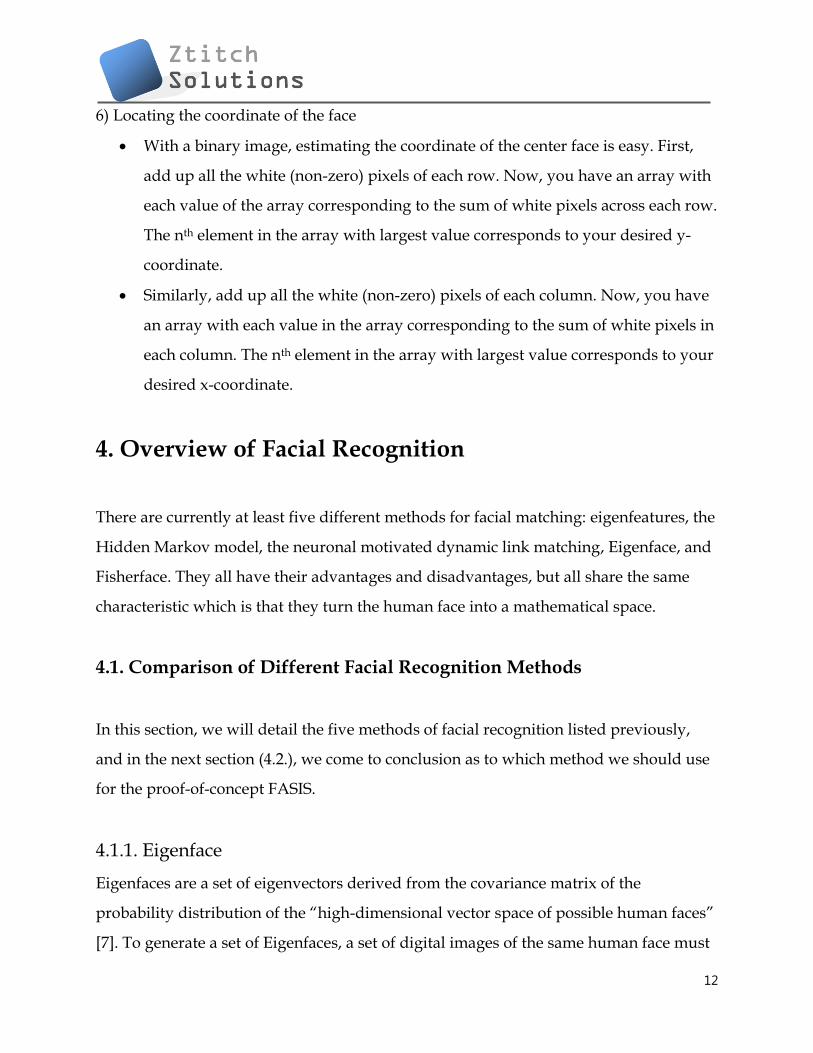
4.1.1. Eigenface
Eigenfaces are a set of eigenvectors derived from the covariance matrix of the
probability distribution of the “high-dimensional vector space of possible human faces”
[7]. To generate a set of Eigenfaces, a set of digital images of the same human face must
13
be taken under the same or similar conditions (both lighting and position wise). The
images are then re-sampled to the same resolution, and the Eigenfaces can be extracted
using a mathematical tool called PCA (principal component analysis).
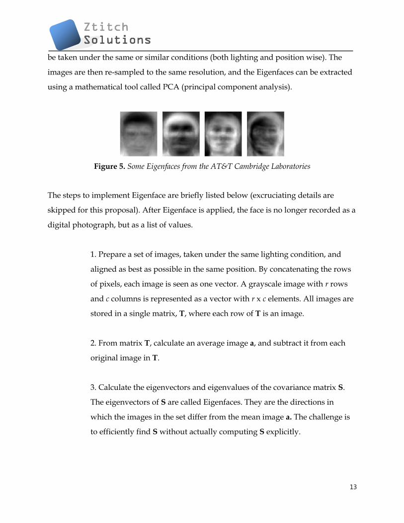
Figure 5. Some Eigenfaces from the AT&T Cambridge Laboratories
The steps to implement Eigenface are briefly listed below (excruciating details are
skipped for this proposal). After Eigenface is applied, the face is no longer recorded as a
digital photograph, but as a list of values.
1. Prepare a set of images, taken under the same lighting condition, and
aligned as best as possible in the same position. By concatenating the rows
of pixels, each image is seen as one vector. A grayscale image with r rows
and c columns is represented as a vector with r x c elements. All images are
stored in a single matrix, T, where each row of T is an image.
2. From matrix T, calculate an average image a, and subtract it from each
original image in T.
3. Calculate the eigenvectors and eigenvalues of the covariance matrix S.
The eigenvectors of S are called Eigenfaces. They are the directions in
which the images in the set differ from the mean image a. The challenge is
to efficiently find S without actually computing S explicitly.
14
4. Choose the principal components. The D x D covariance matrix will
result in D eigenvectors, each representing a direction in the image space.
Keep the eigenvectors with the largest associated eigenvalue.
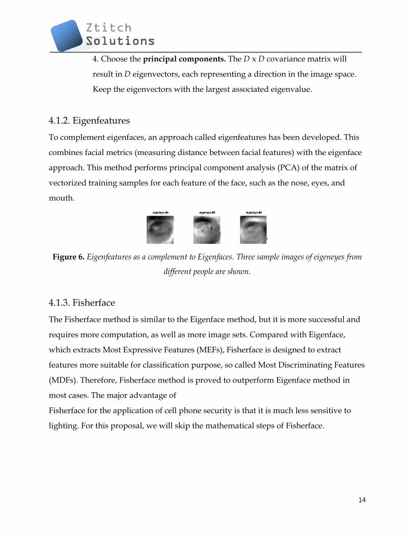
4.1.2. Eigenfeatures
To complement eigenfaces, an approach called eigenfeatures has been developed. This
combines facial metrics (measuring distance between facial features) with the eigenface
approach. This method performs principal component analysis (PCA) of the matrix of
vectorized training samples for each feature of the face, such as the nose, eyes, and
mouth.
Figure 6. Eigenfeatures as a complement to Eigenfaces. Three sample images of eigeneyes from
different people are shown.
4.1.3. Fisherface
The Fisherface method is similar to the Eigenface method, but it is more successful and
requires more computation, as well as more image sets. Compared with Eigenface,
which extracts Most Expressive Features (MEFs), Fisherface is designed to extract
features more suitable for classification purpose, so called Most Discriminating Features
(MDFs). Therefore, Fisherface method is proved to outperform Eigenface method in
most cases. The major advantage of
Fisherface for the application of cell phone security is that it is much less sensitive to
lighting. For this proposal, we will skip the mathematical steps of Fisherface.

15
4.1.4. Eigenface vs. Fisherface Summary
Even though Fisherface yields better result, it has been decided that Eigenface is the
preferred choice for the proof-of-concept FASIS. We have very limited time to complete
this project, and we do not want to get bogged down by the more complex Fisherface
model. In the commercialized FASIS, Ztitch Solutions shall be able to upgrade to a more
accurate method of facial recognition, if the need is required.
Table 1. Comparison of Eigenface versus Fisherface [17]
Fisherface Eigenface
Computational
Complexity
Slightly more
complex Simple
Effectiveness
Across Pose
Good, even with
limited data
Good, with
enough data
Sensitivity to
Lighting Less More
16
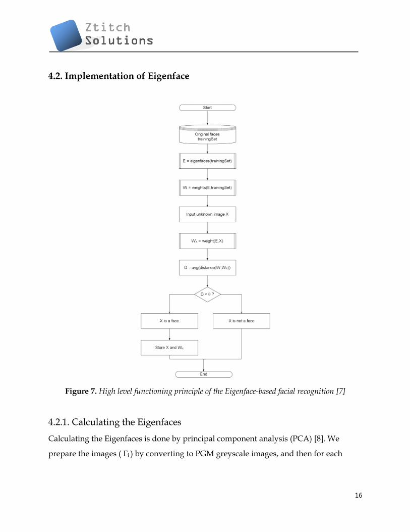
4.2. Implementation of Eigenface
Figure 7. High level functioning principle of the Eigenface-based facial recognition [7]
4.2.1. Calculating the Eigenfaces
Calculating the Eigenfaces is done by principal component analysis (PCA) [8]. We
prepare the images ( Γi ) by converting to PGM greyscale images, and then for each

17
image, we subtract the mean (average matrix). The average matrix is calculated using
the following formula
The result is stored in the variable where
We then calculate the covariance matrix using the formula
Next, we calculate the eigenvectors ui and the corresponding eigenvalues λi. The
eigenvectors are normalized to a unit length of 1. This step is easily done in MATLAB
or Maple with their math libraries.
Finally, from the M number of eigenvectors ui , only M' numbers of eigenvectors are
chosen. The M' eigenvectors have the highest eigenvalues, and therefore corresponds to
eigenvalues described by more facial characteristics. Eigenfaces that have low
eigenvalues are ignored as they explain only an insignificant amount of facial features.
The next section describes the relationship between eigenvectors and eigenvalues. Now,
the training stage is completed.
Unfortunately, the training stage described in this section is not computationally
efficient, as explained in [7]. Luckily, a solution to the problem is presented in [9].

18
4.2.2. Eigenvectors and eigenvalues
An eigenvector u of a matrix M is a vector that if multiplied with the matrix M, the
result is an integer multiple of that vector. This integer value is the corresponding
eigenvalue λ of the eigenvector. The relationship is therefore described by the equation
M × u = λ × u. Eigenvectors possess following properties [10]:
1) Eigenvectors can be determined only for n × n square matrices
2) There are n eigenvectors (and corresponding n eigenvalues) in a n × n matrix.
3) All eigenvectors are perpendicular, i.e. at right angle with each other.
4.2.3. Matching the Faces
Matching a new, unknown face Γnew to one of the known faces Γi involves two steps.
1) Γnew is transformed to the Eigenface, then the weight is calculated as follows:
The weight vector, ΩnewT is
The Euclidean difference between two weight vectors, Ωx and Ωy, is a measure of
similarity between the two corresponding images x and y. If the Euclidean difference
between Γnew and other faces exceeds a certain threshold value, then the image is
probably not a face at all. The Euclidean difference is calculated using the following
equation:

19
5. Secondary Preventative Measures
A secondary preventative measure is required to prevent the determined hackers who
might be using a printed picture of the user to hack the system. This section describes
some of the different methods of security solutions that are possible, and some of them
have already been attempted in various fields. However, none of them prove to be
particularly successful in either preventing mobile phone theft, or stealing personal data
stored in a cell phone.
5.1. Solutions for Secondary Preventative Measures
This section will outline some of these major security systems by describing their
advantages and disadvantages.
5.1.1. Log-in using Password
A password-based login system already exists on most cell phones – it can be enabled
as an option. However, most phones have it disabled from the factory, knowing that
most users will not want to use it.
Advantages:
Easy to implement, as the technology has been established for decades
The least expensive authentication method available
Disadvantages:
For a mobile phone with numeric keypad, only numerical passwords are
supported
Not impossible to bypass, thieves can automate brute force attacks

20
A hassle to use for mobile phones: defeats the purpose of ease and simplicity
Alternate bypass needed for the forgetful users
5.1.2. Fingerprint Identification
Fingerprint authentication system is popular among laptop computers, but the
innovation has not made it to any cell phone on the market.
Advantages:
A proven technology in both commercial and law-enforcement uses
Impossible to reproduce fingerprint, except for genetically identical twins
Quick and easy to gain access for mobile users
Disadvantages:
Susceptible to the quality of the skin: dirty or marked is difficult to image
properly
The scanner increases the size, weight, and cost of the mobile device
The same fingerprint can be difficult to identify after years of certain types of
manual labor
Not unique for about 0.2% of the human population with a genetically identical
twin
5.1.3. Eye Iris Identification
Eye iris authentication is possible, but it requires an iris scanner or a high-quality
camera with specific features. So far, this system has only been deployed to facilitate
airports, border crossings, and various high-security facilities around the world.
Advantages:
Extremely secure: even genetically identical twins have different iris textures
Using John Daughman’s IrisCode, the false rate match is better than 10-11

21
Disadvantages:
Still a new technology, it is expensive to implement in terms of both hardware
and software
Difficult to perform at large distances; susceptible to poor image quality
5.1.4. Speech Recognition
Speech recognition is another alternative that can make use of the phone's existing
hardware, although the technology has not yet been received as a proven security
solution. However, it can be a good substitution as a secondary preventative measure.
Advantages:
No hardware modification required
Looks for two things (1) a specific speech pattern based on the user's vocal
characteristics and (2) a specific spoken password from the user, so the false rate
match can be reasonably well depending on the algorithm
Many open sources available, and easy to implement
Quick to speak, ease of use for the user
Disadvantages:
Not an established security solution in systems
Susceptible to noise, low microphone quality, or any other interference
A human voice can be digitally altered to produce that of another person's
Ztitch Solutions has decided to incorporate speech recognition as the secondary
preventative measure. The combination of facial and speech identification works well -
it is quick, seamless, and easy for the user. Furthermore, it is innovative and the
advantages, as listed above, are notable.

22
5.2. Implementation of Speech Recognition
Microsoft has provided a set of Speech API (SAPI) for 3rd party developers to
incorporate speech recognition in their applications. According to the Microsoft
Developers Network Library [11], the SAPI drastically reduces the code overhead
required and makes it very robust.
The Microsoft SDK is perfect for FASIS because SAPI provides a high-level interface
between an application and speech engines. SAPI implements all the low-level details
needed to control and manage the real-time operations of various speech engines. The
Speech SDK can be used in either C#, C++, VB, or any COM compliant language.
Figure 8. An overview of the Speech API. The two basic types of SAPI engines are text-to-
speech (TTS) systems and speech recognizers. TTS systems synthesize text strings and files into
spoken audio using synthetic voices (not used in FASIS). Speech recognizers convert human
spoken audio into readable text strings and files.
FASIS shall leverage the fact that speech is one of the most natural ways to interact (to
both humans and machine). Immediately after the user has captured the facial image,
the user must provide a spoken password. If the speech recognition is successful, the
system will then accept the face image for facial recognition.

23
6. Controller Module
One of the key goals of the commercialized FASIS is a simple hardware install for the
user, with no hardware modification required. Unfortunately, this can be achieved only
with permission from the OS maker, Symbian, because we need to be able to control the
phone (i.e. locking and unlocking it) remotely from the server. In other words, we need
special APIs from Symbian in order to actually create a socket between the server and
the device. It would be a major security issue if third party developers can actually
remotely control a phone. Therefore, in this proof-of-concept, we need to modify the
hardware so that we can control certain aspects of the phone in order to "simulate" the
lock and unlock events. We can do this most easily by controlling the hardware buttons
of the phone, but using a microcontroller to send small voltages to the buttons in order
to simulate the hardware button-push event.
Note: If this project actually proves itself as being significant and useful for the public,
we can collaborate with Nokia to gain access to the Symbian APIs that allow us to
remotely control a user's phone without adding the external hardware described in this
section.
6.1. The Cell Phone Push Buttons
All electrical circuits need a closed loop to work. The current needs to flow
uninterrupted through the wires and components. A switch is a component that breaks
this loop, and will complete the circuit whenever the switch is activated. There are two
kinds of push buttons: momentary, and non-momentary. The ones found in a phone,
24
typically, are momentary, and work only as long as you press on them. Non-
momentary switches take one push to turn on (i.e. elevator buttons).
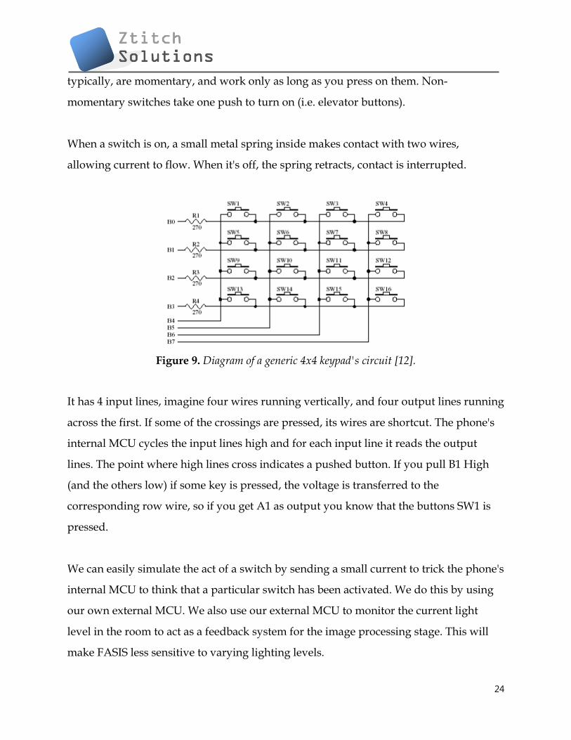
When a switch is on, a small metal spring inside makes contact with two wires,
allowing current to flow. When it's off, the spring retracts, contact is interrupted.
Figure 9. Diagram of a generic 4x4 keypad's circuit [12].
It has 4 input lines, imagine four wires running vertically, and four output lines running
across the first. If some of the crossings are pressed, its wires are shortcut. The phone's
internal MCU cycles the input lines high and for each input line it reads the output
lines. The point where high lines cross indicates a pushed button. If you pull B1 High
(and the others low) if some key is pressed, the voltage is transferred to the
corresponding row wire, so if you get A1 as output you know that the buttons SW1 is
pressed.
We can easily simulate the act of a switch by sending a small current to trick the phone's
internal MCU to think that a particular switch has been activated. We do this by using
our own external MCU. We also use our external MCU to monitor the current light
level in the room to act as a feedback system for the image processing stage. This will
make FASIS less sensitive to varying lighting levels.

25
6.2. Choosing a Microcontroller Module
There are a variety of hobbyist and student microcontroller kits to choose from in the
market, and we have chosen to use the Parallax Board of Education Kit [13] for the
following reasons:
1. Includes the BASIC Stamp 2 microcontroller module, which is a robust and proven
microcontroller amongst enthusiasts and students like us.
2. USB connection for programming and communication during run-time.
Communication during run-time is absolutely crucial to this project, as we want to have
a GUI on the PC (server) to allow us to control the phone in close to real-time.
3. Provides a clean, efficient platform for the MCU, and also has a built-in breadboard
for our custom prototyping circuits.
4. Numerous resources, information, and tutorials for the Parallax kit are available
online.
6.3. Parallax Board of Education
Figure 10. An image of the Parallax BOE without the MCU (source: Parallax manual)

26
The following information is extracted directly from the Parallax BOE manual:
1. 9V Battery Clip: You can use alkaline or rechargeable 9 volt batteries. The battery clip
and barrel jack are intentionally positioned so you cannot use both at once.
2. Barrel Jack: This accepts a 2.1 mm center-positive barrel plug from a 6-9 V wall-
mount supply or from a battery pack. You cannot use the barrel jack and a 9 volt battery
at the same time.
3. Voltage regulator: Supplies regulated 5 V (up to 1 amp of current) for sockets and
pins labelled Vdd. Vdd sockets are convenient for supplying 5 V to circuits you will
build on the breadboard area.
4. Power Indicator LED: This LED will light up when power is supplied to your board
and the power switch is in position 1 or 2.
5. Servo headers (X4 and X5) and Power Select Jumper: These each have two 3-pin
connectors that bring power, ground, and I/O pin access together so you can easily
plug in servos or other 3-pin devices. The power connection is pre-set to Vdd (+5 V) but
you can set it to Vin (the board's supply voltage) by moving the shorting block on the
jumper between the headers. Each 3-pin row is labeled with an I/O pin number above
it. The 12, 13, 14, and 15 signal lines for the servo headers are also accessible as P12, P13,
P14, and P15 I/O pin sockets on the X1 and X2 headers. This can be useful for building
a servo signal indicator light on the breadboard as you may do in some Stamps in Class
activities. For independent projects, keep these shared connections in mind, especially
to avoid inadvertently connecting circuits with conflicting functions to the same I/O
pin.

27
6. Power header (X3): The sockets labeled Vdd connect to +5 VDC, Vin connects
directly to the power supplied to the board by the battery clip or barrel jack, and Vss
connects to 0 V (ground).
7. Breadboard: The breadboard has metal clips that run underneath the white plastic
board in a horizontal fashion. Each strip connects a 5-socket group, with two groups to
each row, separated by a center trench. Wires or legs of components plugged into the
same 5-socket group will be electrically connected. Components with many legs (such
as pushbuttons or ICs), are placed in the middle of the board so that half of the legs are
on the left side and half are on the right side of the trench. Note: Always disconnect
power before building or modifying circuits!
8. I/O Pin Access Header (X2): The BASIC Stamp module's 16 I/O pins, labeled 0 to 15,
are connected to this header. Its location adjacent to the breadboard makes it convenient
for connecting circuits to I/O pins. Keep in mind that I/O pin access is also brought to
the X4, X5, and X1 headers, so be careful not to build conflicting breadboard circuits if
you are using these other headers as well.
9. AppMod header (X1): The AppMod header provides power, I/O pins, Vdd, Vin, and
Vss access for any devices that are designed to use this 2x10 socket. Examples include
the LCD Terminal AppMod (#29121), CMUcam (#30051), Easy Bluetooth Module
(#30085), and Say It voice recognition module (#30080).
10. Reset Button: The reset button can be used to restart your BASIC Stamp without
having to cycle the power. This saves wear-and-tear on the power switch for simple
program restarts. Some advanced programming techniques use the reset button and the
BASIC Stamp EEPROM program and data storage as a way to toggle between different
program functions.

28
11. 3-Position Power Switch: The leftmost position (0) is OFF – all power is
disconnected. Always place the switch in this position when adding or changing
components on the breadboard. The middle position (1) provides Vin (unregulated
battery or power supply voltage) to the regulator, the BASIC Stamp socket, and to the
connectors marked “Vin.” This switch position also makes Vdd (5 volts) available to
Vdd sockets on the breadboard and AppMod connectors. The rightmost position (2)
also provides power to the servo connectors X4 and X5. Especially if your program
causes a robot with servos connected to X4/X5 to start moving immediately, you can
keep the 3-position switch in position (1) while loading the program, then switch to
position (2) when you are ready for the robot to start moving.
12. Socket for BASIC Stamp: This socket is compatible with all 24-pin BASIC Stamp
modules. It connects the BASIC Stamp to the programming connector, power, the
power indicator LED, reset button, and all I/O pin headers.
13. USB Programming Connector: This is a USB Mini B socket and USB to serial
(RS232) circuitry for programming and for two-way serial communication between the
BASIC Stamp and your computer. The required USB drivers for Windows were
included in the BASIC Stamp Editor

29
Figure 11. The BOE schematics (source: Parallax manual)

30
6.3.1. Light Sensor Circuit using the BOE
We shall also implement a light sensor to act as a feedback system for the image
processing stage to increase or decrease brightness/contrast level of the image. The
following circuit, along with the code, construct a simple light level monitor [13].
Figure 12. Circuit and coding for a light sensor using the Parallax kit
7. Client-Server Connection
This section will discuss the connection pathway between client and server. In
particular, this section will discuss the method Ztitch Solution will take in order to
establish a communication such that data can be relayed from the user to the server and
vice-versa.

31
7.1. Transceiver Module
By definition, a transceiver is any device that is both a transmitter and receiver of data,
electromagnetic signal, radio, television, or any other telecommunications.
As discussed in the functional specification document [1], the commercialized FASIS
uses the phone's internal wireless transceiver to transmit the image data and retrieve
the unlocking code to/from the server over the air (2G/3G, etc). In this proof-of-concept
system, however, we simulate this portion by simply using the serial port of the phone,
which is actually a RS232 debugger terminal attached to an external hardware module
(described in the next section).
7.1.1. RS232 Transceiver
At the heart of this module is the Maxim MAX3222E, which is a 'true' RS232 transceiver.
The datasheet of this chip can be found in [14]. The chip has the following properties:
1) Requires four 0.1μF external charge pump capacitors.
2) Guaranteed to run at data rates of 120kbps and maintaining RS232 output levels.
3) 2 receivers and 2 drivers
4) Low power consumption
Applications:
• Notebook, Subnotebook, and Palmtop Computers
• High-Speed Modems
• Battery-Powered Equipment
• Hand-Held Equipment
• Peripherals

32
7.1.2. Power Supplies
According to Maxim's website [15], RS232-compliant parts need a minimum of two
supply voltages, one that is greater than +5V and one that is less (more negative) than -
5V. These two supplies are needed to guarantee the minimum +/-5V output swings
required for the transmitters. See figure 13. In systems that already have +/-12V, this
isn't a problem. However, in systems being designed today, +/-12V (or other voltages)
aren't usually available. To solve this problem, Maxim has designed a wide array of
parts that can be powered from a single supply by including power-supply converters
built directly onto the IC.
Figure 13. RS232 transmitters must swing at least ±5V. This means that they must be powered
with supplies ±5V (source: Maxim's website [15])
Although single 5V-only parts are great in a lot of cases, an increasing number of
applications require parts that will run from a single 3.3V supply. For instance, the
battery voltage of a Nokia phone is 3.6V. Operation with 3.3V is not just important in
3.3V-only systems, but also where the RS232 parts must interface to 3V logic.

33
Figure 14. RS232 application circuit for 3.6V using the MAX3222E chip (source: Maxim's
website [15])
As shown in figure 14, the circuit has two charge-pump power supplies built on-board.
These RS232 parts are special because of their low-dropout transmitters. These
transmitters can meet the minimum-required +/-5V swings, while running from
charge-pump power supplies as low as +/-5.5V. This makes it possible for these parts to
run from a single 3.0V supply and still be fully compliant with the RS232 specification.
Although these parts will run on supplies as low as 3.0V, they have also been designed
to run as high as 5.5V.
7.2. Minimizing Data Transfer
Data compression is required to minimize the amount of data (particularly the size of
each image) so that the upload time is minimized. Furthermore, a shrunken image will
result in lower bandwidth costs and an overall better user experience. It also reduces
34
the amount of work the server needs to do. The task is to shrink the image at the client
side, immediately after the image is captured, and before the image is sent.
Luckily, some resources are available that delve in the topic of image compression on a
Nokia phone. One such example can be found in [16]. The code, which is open source
and suited for the Symbian S60V3 (N96's OS), can be found in Appendix I.
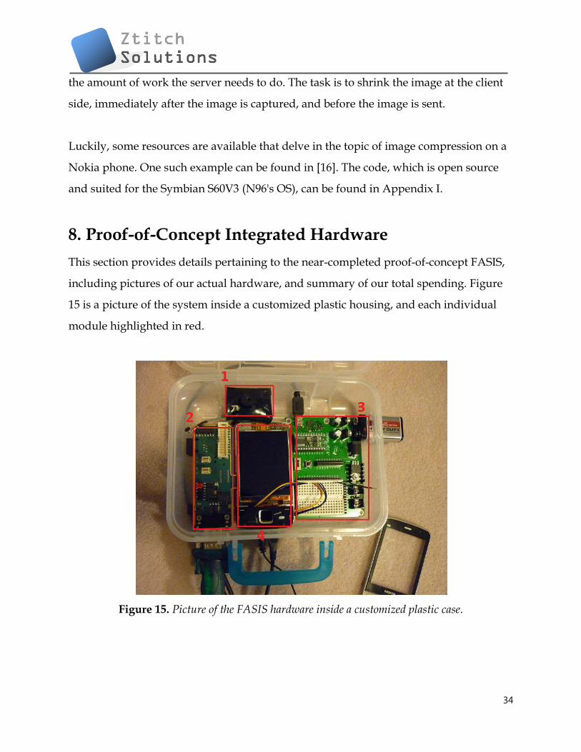
8. Proof-of-Concept Integrated Hardware
This section provides details pertaining to the near-completed proof-of-concept FASIS,
including pictures of our actual hardware, and summary of our total spending. Figure
15 is a picture of the system inside a customized plastic housing, and each individual
module highlighted in red.
Figure 15. Picture of the FASIS hardware inside a customized plastic case.

35
The modules highlighted in figure 15 are as follows:
1 - Internet camera (for the purpose of debugging and testing the facial
localization and recognition algorithms only)
2 - Transceiver module (see section 7)
3 - Parallax Board of Education (BOE) including breadboard* (see section 6)
4 - Nokia N96 phone partially disassembled and wired to the BOE
*Note: The breadboard circuitry is not yet completed.
With the cables disconnected and internet camera removed, the FASIS prototype is
easily portable, as shown in figure 16.
Figure 16. The FASIS concept as a portable module.
Table 2 outlines our total spending for the project. All prices are approximate, and the
total cost is about $250 CAD, so we have successfully achieved our budget goal of less
than $800, thanks to Nokia who provided us with the device. Students also have access
to Visual Studio and Matlab for free which significantly reduced the total cost of this
project.

36
Table 2. Budget Summary
Item Cost (CAD, includes tax)
Nokia N96 smart phone unlocked $0 (provided by Nokia)
Active SIM card plus subscription $0
Transceiver module $60
Parallax BOE $160
Software Tools, SDKs, drivers, etc. $0 (free for students)
Cases, stands, and misc. accessories $30 Total Cost $250
9. System Test Plan
To ensure strong confidence and quality assurance of the system, comprehensive
testing will be performed at all stages of development. Tests will be performed on the
unit components, but a set of test cases (simulations) will also be developed to cover a
wide range of use-case scenarios in the final overall system. These tests are intended to
discover bugs so that they can be alleviated as early as possible. In the proof-of-concept
system, some testing of the hardware will also be required to ensure that project demo
will go flawlessly. However, the commercialized system will contain no such hardware
modification, since data is transferred over the network rather than an external
communications board, so the hardware test stage will not be as comprehensive as the
software test stage.
9.1. Unit Test
The proof-of-concept FASIS system can be divided into three sub-units: an application
on the phone, a hardware communication board to relay information between the
phone and the PC, and the server/PC providing the services.

37
The phone software can be tested by triggering FASIS by attempts to access secured
data. The expected response is the camera application opening up which also powers
up the front-facing camera. A button is then pressed (either the camera capture button
or the center push button). The image then awaits transfer to the PC. Fortunately, these
two steps can be automated using a USB connection controlled by Nokia’s HTI
(Harmonized Test Interface). The test will be running in loops that try to access
different secured data of the phones, and each time, FASIS is expected to fire up. Then,
in the second step, the automation should trigger the camera capture by simulating the
push of a button, and the expected response is an image now waiting to be transferred.
Testing of the hardware communication board can be done by sending data from the
phone to the PC, and vice-versa. We then verify that the data is sent successfully
without loss. FASIS will only relay data in two forms: an encoded bitmap image, and an
encrypted key. This sub-unit of the system will be tested manually only, because this
component will not appear in the final commercialized product, since data will actually
be relayed over the network rather than an external board.
The facial matching algorithm can be tested independently from the other sub-units,
with the only required input being a small image containing the face. The expected
response is an encrypted key which contains the instruction for the phone to either lock
or unlock the device. Testing of this sub-unit can also be automated, which is important.
The facial matching algorithm will most likely undergo many revisions, and if we
automate this step, it can save a lot of time by running the automated test after each
revision compared to manually testing the algorithm. During each cycle of the test, one
image will be chosen either randomly or from a consecutive list from a set of many
different images. The database of test images will be derived from many different faces
38
that exhibit a wide range of variations of facial features and skin color; this can ensure
accuracy for all types of faces.
Test cases for the individual modules will include, but not limited to, the following:
Microcontroller: HTI test
- Connect the modules' ports; Parallax Board N96
- Run HTI
Expected result: A connection is established with expected code returned.
Microcontroller: Test the phone's controllability via PC
- Launch HyperTerminal
- Send instruction to launch the application
Expected result: The application is launched
- Repeat the previous step with all possible instructions and ensure that the
phone behaves accordingly.
Transceiver: Test data being received from the phone
- Send an image (jpeg) from the phone to the PC
Expected result: Image is sent with no data loss
- Repeat with various image file sizes (2kB, 4kB, 8kB, etc)
Facial Localization: Test that localization is successful in a variety of lighting conditions
- Move the face around but maintain exposure to the webcam
Expected result: The face is always tracked inside a marker
- Repeat the previous step and vary the light level in the room
Facial Localization: Test that localization is successful with a wide range of skin colors
- Use printed samples of skin colors on paper, repeat the previous test case
39
Expected result: The piece of paper is tracked
- If test fails, adjust the color threshold of the algorithm
-If it still fails, fix the problem within the algorithm
Facial Recognition: Test different users
- Attempt facial recognition with images of the known face
Expected result: The user should be recognized
- Attempt facial recognition with images of unknown faces (users that do not
exist in the database)
Expected result: The unknown users are not recognized
Facial Recognition: Add/Remove user in database
- Delete the database, and add a new user
- Attempt facial recognition
Expected result: only the new user should be recognized
9.2. Automated Tests
Testing will be automated whenever possible. The software portion of the project will
be updated frequently, and these software components include the algorithm for facial
matching, the logic for locking/unlocking the phone, and the transfer of data between
the phone and the server/PC. Since they are updated frequently, we want to save time
by automating these tests rather than have a member of the group manually test them
each time they are updated.
The objective here is to test each component with a variety of input arguments to
validate that the returned results are correct. Automated tests can be executed using
batch files and with a free software test tool called AutoIt. These automated tests can be
prescribed to run a specific number of loops for stress testing.
40
9.3. Integrated Test and Simulation
After each component has satisfied its requirement, an integrated test will be performed
to ensure final product quality and that the performance meets the requirements.
Simulations will cover actual use-case scenario: each member of the team will act as the
owner of the device, and have his/her face data stored in the database. We will ask
people from around the campus to be part of the tests, and these unrecognized users
should not be authenticated. Furthermore, we will try to vary the lighting conditions by
switching to different environments during these tests. The success rate should be at
least 95%. Of course, the lighting conditions are assumed to be reasonable, both indoors
and outdoors. However, areas of complete darkness or extreme brightness will
probably not occur in practical situations, and would most likely cause the facial
matching algorithm to fail, so we will not test in these areas.
If a test fails during the integrated stage, we will try to fix the component causing the
failure and execute unit testing before repeating the integrated tests.
Simulation test cases for the integrated FASIS will include, but not limited to, the
following:
Integrated FASIS: Use-case scenario
-Manually trigger FASIS on the phone by attempting to access secured storage.
Expected result: FASIS application launches, front-facing camera fires up.
-Snap a picture of the face.
Expected result: The image is captured and shown.
-Speak password to the microphone.
Expected result: FASIS queries the spoken password.

41
-If spoken password is recognized, FASIS facial recognition
-If facial recognition is successful, the phone is unlocked.
-If facial recognition is unsuccessful, the phone is locked.
-If spoken password is not recognized, the facial image is NOT accepted.
42
10. References [1] Ztith Solutions Inc., "Functional Specification for a Facial and Speech Identification System for Nokia Devices", Simon Fraser University, Burnaby, BC, Canada, Oct 14 2010. [2] Tony Jebara, "3D Pose Estimation and Normalization for Face Recognition", Columbia University, Jun 2000. [Online]. Available: http://www.cs.columbia.edu/~jebara/htmlpapers/UTHESIS/node32.html [Accessed: Oct 1, 2010]. [3] Gang-Qiang Zhao et al, "A simple 3D face tracking method based on depth information," in Proc. of the 4th International Conference on Machine Learning and Cybernetics, Guangzhou,18-21 August 2005. [4] Lamiaa Mostafa and Sherif Abdelazeem, "Face Detection using Skin Color Using Neural Networks", Information Technology Institute, Giza, Egypt, Mar 26, 2006. [5] Rene Schulté, "Real-Time Face Detection", Dresden, Germany, Mar 2010. [Online]. Available: http://blogs.msdn.com/b/coding4fun/archive/2010/03/24/9984015.aspx [Accessed: Oct 5, 2010]. [6] Erik Hjelmås, "Recognizing Faces from the Eyes Only", University of Oslo, Oslo, Norway, Jan 1999. [Online] Available: http://www.ansatt.hig.no/erikh/papers/scia99/scia99.html [Accessed: Oct 14, 2010]. [7] SourceForge, "Eigenface-based facial recognition", 2003. [Online] Available: http://openbio.sourceforge.net/resources/eigenfaces/eigenfaces-html/facesOptions.html [Accessed: September 11, 2010]. [8] D. Pissarenko, Neural networks for financial time series prediction: Overview over recent research. BSc thesis, Technical report, Austrian Partners, 2002. [9] M. Turk and A. Pentland. Eigenfaces for recognition. Journal of Cognitive Neuroscience, 3 (1), 1991a. Available: http://www.cs.ucsb.edu/ mturk/Papers/jcn.pdf. [Accessed: November 27, 2002]. [10] E. Garcia , "Matrix Tutorial 3: Eigenvalues and Eigenvectors", Mi Islita, 2006. [Online] Available: http://www.miislita.com/information-retrieval-tutorial/matrix-tutorial-3-eigenvalues-eigenvectors.html [Accessed: Oct 18, 2010]

43
[11] Microsoft, "Speech API Overview (SAPI 5.4)", Redmond, USA, 2009. [Online] Available: http://msdn.microsoft.com/en-us/library/ee125077%28VS.85%29.aspx [Accessed: Oct 20, 2010] [12] J. T. Barett, "How do Push Buttons Work in an Electrial Circuit?", eHow, date unknown. [Online] Available: http://www.ehow.com/how-does_5030234_push-switches-work-electrical-circuit.html [Accessed: Oct 21, 2010] [13] Parallax, Manual for Board of Education Kit, Rocklin, California, USA, 2009. [Online] Available: http http://www.parallax.com/dl/docs/prod/boards/28850-BOE-USB-v1.4.pdf [Accessed: Oct 21, 2010] [14] Maxim, MAX3222-MAX3241 True RS232 Transceivers Datasheet, 2007. [Online] Available: http://pdfserv.maxim-ic.com/en/ds/MAX3222-MAX3241.pdf [Accessed: Oct 22, 2010] [15] Maxim, Selecting and using RS-232 Interface Parts for Your Power Supply Voltages, Sunnyvale, Calfironia, Jan 2001. [Online] Available: http://www.maxim-ic.com/app-notes/index.mvp/id/836 [Accessed Oct 25, 2010] [16] Nokia, "Compressing and Decompressing Files Using CEZFileBufferManager", Finland, 2008. [Online] Available: http://wiki.forum.nokia.com/index.php/CS000950_-_Compressing_and_decompressing_files_using_CEZFileBufferManager [Accessed Nov 1, 2010] [17] Daily Burito. 2004. Face Recognition: Eigenface and Fisherface Performance Across Pose. http://dailyburrito.com/projects/facerecog/FaceRecReport.html#refs [Accessed: September 14, 2010]

44
Appendix I
void CompressFileL(RFs &aFs, TInt aBufferSize, TInt aMethod, const TDesC& aFileName)
{
TInt err(KErrNone);
RFile input;
RFile output;
HBufC *compressedFile = HBufC::NewLC(aFileName.Length()+2);
_LIT(KCompressedFileName,"%S.c");
compressedFile->Des().Format(KCompressedFileName,&aFileName);
User::LeaveIfError(input.Open(aFs,aFileName,EFileStream | EFileRead | EFileShareAny));
CleanupClosePushL(input);
err = output.Create(aFs, *compressedFile,EFileStream | EFileWrite | EFileShareExclusive);
if (err == KErrAlreadyExists)
User::LeaveIfError(output.Open(aFs, *compressedFile,EFileStream | EFileWrite |
EFileShareExclusive));
else
User::LeaveIfError(err);
CleanupClosePushL(output);
CEZFileBufferManager *fileBufferManager = CEZFileBufferManager::NewLC(input,output,
aBufferSize);
CEZCompressor *compressor = CEZCompressor::NewLC(*fileBufferManager, aMethod);
_LIT(KCompressingFileText,"Compressing file %S to %S\n");
console->Printf(KCompressingFileText,&aFileName,compressedFile);
while (compressor->DeflateL())
{
// loop here until the file is compressed
}
CleanupStack::PopAndDestroy(5); //compressor,bufManager,output,input,compressedFile
}
void DecompressFileL(RFs &aFs, TInt aBufferSize, const TDesC& aFileName)
{
TInt err(KErrNone);
RFile input;

45
RFile output;
User::LeaveIfError(input.Open(aFs, aFileName,EFileStream | EFileRead | EFileShareAny));
CleanupClosePushL(input);
HBufC *decompressedFile = HBufC::NewLC(aFileName.Length()+2);
_LIT(KDecompressedFileName,"%S.d");
decompressedFile->Des().Format(KDecompressedFileName,&aFileName);
err = output.Create(aFs, *decompressedFile,EFileStream | EFileWrite | EFileShareExclusive);
if (err == KErrAlreadyExists)
User::LeaveIfError(output.Open(aFs, *decompressedFile,EFileStream | EFileWrite |
EFileShareExclusive));
else
User::LeaveIfError(err);
CleanupClosePushL(output);
CEZFileBufferManager *fileBufferManager =
CEZFileBufferManager::NewLC(input,output,aBufferSize);
CEZDecompressor *decompressor = CEZDecompressor::NewLC(*fileBufferManager);
_LIT(KDecompressingFileText,"Decompressing file %S from %S\n");
console->Printf(KDecompressingFileText,decompressedFile,&aFileName);
while (decompressor->InflateL())
{
// loop here until the file is decompressed
}
CleanupStack::PopAndDestroy(5); //decompressor,bufManager,output,input,decompressedFile
}