and TiC prepared by self-propagating high-temperature ...
10
JOURNAL OF MATERIALS SCIENCE 29 (1994) 534-543 Structural and mechanical properties of TiB2 and TiC prepared by self-propagating high-temperature synthesis/dynamic compaction L. WANG, M. R. WIXOM T/J Technologies, Inc., Northville, Mi 48167, USA L. T. THOMPSON The University of Michigan, Department of Chemical Engineering, Ann Arbor, MI 48109-2136, USA Titanium-diboride and titanium-carbide compacts with diameters of 1O0 mm and thicknesses of 25 mm were fabricated by self-propagating high-temperature synthesis/dynamic compaction (SHS/DC) of the elemental powders. Under the best conditions, the densities were greater than 99% and 96.8% of the theoretical densities for TiB 2 and TiC, respectively. The microhardness, compressive strength, and elastic modulus of the TiB 2 prepared by the SHS/DC method were comparable to reported values for hot-pressed TiB 2. While the microhardness and elastic modulus of the TiC compacts were comparable to those for hot- pressed TiC, the compressive strength was lower due to extensive cracks in the compacts. The TiB 2 prepared using a low-purity boron powder (1-5% carbon impurity) compacted to higher densities and had less cracking than that prepared using a high-purity boron powder (0.2% carbon). This result could have an impact on the cost of producing TiB2/TiC structural components by the SHS/DC process. 1. Introduction There is growing interest in the use of titanium- diboride and titanium-carbide ceramics because of their high melting points, hardness, compressive strength, excellent wear resistance, and light weight. In addition, they are thermally shock resistant and chem- ically stable. These properties make TiB 2 and TiC attractive for applications including use in light ar- mour, cutting tools, wear parts, and jet-engine com- ponents [1-5]. The fabrication of TiB 2 and TiC ceramics by conventional sintering, hot pressing or hot isostatic pressing of TiB 2 and TiC powders is costly because of the time-intensive and facility-intensive nature of these processes. The commercial application of TiB 2 and TiC ceramics has thus been limited. A self-propag- ating high-temperature synthesis technique (SHS) when combined with dynamic compaction (DC) may provide an economic method for producing dense bodies of TiB 2 and TiC from the elemental powders. The SHS process takes advantage of the extreme heat generated during the formation of some refractory materials. When a compact of the constituent ele- mental powders is ignited, the highly exothermic reac- tion propagates spontaneously and rapidly, and converts the reactants into a refractory product. This technique has attracted attention as a route to a variety of refractory materials including borides, carb- ides, nitrides, silicides and intermetallic compounds [6-21]. The SHS products, however, cannot be used directly as structural materials because they are gen- erally quite porous (the porosity can be as high as 50 vol %). This limitation can be overcome by com- bining the SHS reaction with a densification step. In the SHS/DC technique, hot, porous, ceramic bodies formed during the SHS reactions are consolidated to high density by the action of a pressure wave gener- ated from the detonation of a high explosive and/or the impact of an explosively driven flyer plate. The SHS/DC technique has the merit of being less depend- ent on expensive facilities and higher in throughput than other techniques. The SHS/DC technique has been studied by re- searchers at the US Army Ballistic Research Laborat- ory [22-25], and at New Mexico Tech. [26-28]. They demonstrated that, under appropriate conditions, near fully dense TiB 2, TiC and HfC ceramics could be prepared using this technique. Valuable informa- tion regarding the effects of the powder characteristics, inert diluent, impurities, delay time and C/M ratio (ratio of the explosive mass to the metal driving plate mass) on the synthesis and compaction was obtained. However, information about the mechanical proper- ties of SHS/DC-prepared compacts is generally lack- ing. The objective of the research described in this paper was to evaluate the structural and mechanical 534 0022-2461 1994 Chapman & Hall
Transcript of and TiC prepared by self-propagating high-temperature ...

J O U R N A L O F M A T E R I A L S S C I E N C E 29 (1994) 5 3 4 - 5 4 3
Structural and mechanical properties of TiB2 and TiC prepared by self-propagating high-temperature synthesis/dynamic compaction
L. WANG, M. R. WIXOM T/J Technologies, Inc., Northville, M i 48167, USA
L. T. THOMPSON The University of Michigan, Department of Chemical Engineering, Ann Arbor, MI 48109-2136, USA
Titanium-diboride and titanium-carbide compacts with diameters of 1 O0 mm and thicknesses of 25 mm were fabricated by self-propagating high-temperature synthesis/dynamic compaction (SHS/DC) of the elemental powders. Under the best conditions, the densities were greater than 99% and 96.8% of the theoretical densities for TiB 2 and TiC, respectively. The microhardness, compressive strength, and elastic modulus of the TiB 2 prepared by the SHS/DC method were comparable to reported values for hot-pressed TiB 2. While the microhardness and elastic modulus of the TiC compacts were comparable to those for hot- pressed TiC, the compressive strength was lower due to extensive cracks in the compacts. The TiB 2 prepared using a low-purity boron powder (1-5% carbon impurity) compacted to higher densities and had less cracking than that prepared using a high-purity boron powder (0.2% carbon). This result could have an impact on the cost of producing TiB2/TiC structural components by the SHS/DC process.
1. In t roduct ion There is growing interest in the use of titanium- diboride and titanium-carbide ceramics because of their high melting points, hardness, compressive strength, excellent wear resistance, and light weight. In addition, they are thermally shock resistant and chem- ically stable. These properties make TiB 2 and TiC attractive for applications including use in light ar- mour, cutting tools, wear parts, and jet-engine com- ponents [1-5].
The fabrication of TiB 2 and TiC ceramics by conventional sintering, hot pressing or hot isostatic pressing of TiB 2 and TiC powders is costly because of the time-intensive and facility-intensive nature of these processes. The commercial application of TiB 2 and TiC ceramics has thus been limited. A self-propag- ating high-temperature synthesis technique (SHS) when combined with dynamic compaction (DC) may provide an economic method for producing dense bodies of TiB 2 and TiC from the elemental powders. The SHS process takes advantage of the extreme heat generated during the formation of some refractory materials. When a compact of the constituent ele- mental powders is ignited, the highly exothermic reac- tion propagates spontaneously and rapidly, and converts the reactants into a refractory product. This technique has attracted attention as a route to a variety of refractory materials including borides, carb-
ides, nitrides, silicides and intermetallic compounds [6-21]. The SHS products, however, cannot be used directly as structural materials because they are gen- erally quite porous (the porosity can be as high as 50 vol %). This limitation can be overcome by com- bining the SHS reaction with a densification step. In the SHS/DC technique, hot, porous, ceramic bodies formed during the SHS reactions are consolidated to high density by the action of a pressure wave gener- ated from the detonation of a high explosive and/or the impact of an explosively driven flyer plate. The SHS/DC technique has the merit of being less depend- ent on expensive facilities and higher in throughput than other techniques.
The SHS/DC technique has been studied by re- searchers at the US Army Ballistic Research Laborat- ory [22-25], and at New Mexico Tech. [26-28]. They demonstrated that, under appropriate conditions, near fully dense TiB 2, TiC and HfC ceramics could be prepared using this technique. Valuable informa- tion regarding the effects of the powder characteristics, inert diluent, impurities, delay time and C/M ratio (ratio of the explosive mass to the metal driving plate mass) on the synthesis and compaction was obtained. However, information about the mechanical proper- ties of SHS/DC-prepared compacts is generally lack- ing. The objective of the research described in this paper was to evaluate the structural and mechanical
534 0022-2461 �9 1994 Chapman & Hall

properties of TiB z and TiC compacts prepared by the SHS/DC technique, and to correlate the microstruc- tural development and mechanical properties with the processing conditions.
~f'Detonator_
PVC tube
Detasheet er
2. Experimental procedure 2.1. SHS react ion and d y n a m i c compac t i on The starting materials were elemental powders of titanium, carbon and boron. The purity, particle size and supplier of the powders are summarized in Table I. Two different boron powders were used. The B-1 powder contained 1-5% carbon, whereas the B-2 powder was > 99.5% pure. The particle sizes were selected as a compromise between the reduced reac- tion rate of larger particles, the inconvenience of handling smaller particles and the potential for surface contamination [23].
The B/Ti atomic ratio of 2:1 and C/Ti atomic ratio of 0.95 : 1 were selected on the basis of the results of previous work. A stoichiometric B/Ti ratio has been widely used, whereas a range of C/Ti atomic ratios have been employed (0.7 to 1.19) [9, 22, 23, 28]. Several researchers have suggested that the optimum C/Ti atomic ratio for SHS/DC is 0.95 [28, 29]. There are at least two reasons for the use of substoichio- metric C/Ti ratios [30]. First, the violent release of impurities can cause expulsion of titanium from the compact [31]. Secondly, at the elevated temperatures at which compaction occurs, non-stoichiometric TiC has a lower yield strength than stoichiometric TiC [32].
The Ti -B and Ti -C powders were dry mixed under an argon atmosphere for 12 h in a V-shaped, plastic, mechanical blender. Since no milling media was used, the possibility of contamination during mixing was minimal. The mixtures were uniaxially pressed into disc-shaped greenforms (100mm in diameter and ~ 40 mm in thickness) under a pressure of greater than 20 MPa using a hydraulic press. The relative densities of the resulting greenforms were ~ 60% of the theoretical values. Subsequently, the greenforms were stored in a vacuum chamber to prevent oxida- tion.
The experimental set-up for the SHS/DC is shown in Fig. 1. This system was designed by Thadhani and co-workers [26-28] at New Mexico Tech. where the present shock-compaction experiments were per- formed. The system was made up of layers of gypsum wall-board which were centre-cored to a diameter slightly larger than that of the reactant greenforms. Two telescoping mild-steel rings of equal height were placed between the greenform and the gypsum to provide lateral containment during the reaction and
TAB LE I Specifications of the starting materials
Material Purity Particle size Supplier
Ti 99.5% - 325 mesh Micro Metals B-I > 95% - 325 mesh Aldrich B-2 99.5% - 325 mesh Atlantic C (graphite) 99.9% 2 lain Consolid. Astron.
Wooden-bolt [ ,-; ) support system
I 1 ~ . . , ~ ~L2 mm zirconia felt .......................... - --Electric match with i ~ l l I __ _mJ~ ignition powder Steel rings ~ ~ . ; . ; .~ . ; . ; . ; . : . ;~
Grafoil-~ t ~i~q~q;r~ni Vent hole Thermocouple -1
Figure 1 Experimentalset-up for self-propagating high-temper- ature synthesis/dynamic compaction (SHS/DC).
subsequent compaction. The bottom ring and the gypsum block had four matching holes to vent gases released during the reaction. A Grafoil strip was placed between the steel ring and the greenform to provide thermal insulation and to prevent impurities from diffusing into the reacted compact. Circular driver plates and momentum traps made of high- hardness steel (MIL SPEC 46100) were epoxied into wooden frames, and lined with zirconia felt and a
Grafoil sheet. The explosive loading assembly consisted of a PVC
tube into which a 120 ~ gypsum cone was cast. The cone was lined with a Detasheet booster and filled with ANFO (ammonium nitrate mixed with 6 wt % fuel oil) explosive with a density of 900 kg m - 3 and a detonation velocity of 3480ms -1. Such a cone- initiated, explosive-charge assembly provided a much more uniform pressure loading than that generated using sweeping-wave initiation of the explosive charge [26, 28].
Loose powder of the same composition as that of the reactant mixture was placed on the top of the greenform. The powder was ignited by an electric match using a 115 V source. This in turn set off the reaction between titanium and boron or titanium and carbon in the greenform. The reaction wave travelled down toward the bottom surface of the greenform, and progress of the reaction was tracked using a chromel-alumel thermocouple attached to the surface of the momentum trap. The delay time (the time between reaction completion and explosive compac- tion) was varied in an attempt to enhance the densities of the compacts. The same experimental set-up was used for the synthesis of both TiB 2 and TiC.
The experimental conditions employed for .*he Ti -B and Ti -C systems are summarized in Table II. Flyer plates 200 mm in diameter were used for the Ti B system, whereas both 200 and 300 mm plates were used for the T i -C system. The C / M ratio reflects the pressure applied to the samples during the explosion.
535

T A B L E II Experimental Conditions for the SHS/DC of TiB2 and TiC
Sample Composit ion C/M ratio Time delay Fixture Precursor (s) (mm)
TB9224 B/Ti = 2: 1 0.2 10 200 B- 1 TB9225 B/Ti = 2:1 0.2 5 200 B-1 TB9244 B/Ti = 2:1 0.2 10 200 B-2 TB9245 B/Ti = 2:1 0.2 15 200 B-2 TB9246 B/Ti = 2:1 0,2 20 200 B-2 TC9223 C/Ti = 0,95 : 1 0.6 5 200 C TC9241 C/Ti = 0.95:1 0.4 5 200 C TC9242 C/Ti = 0.95 : 1 0.4 10 300 C TC9243 C/Ti = 0.95 : 1 0.6 5 300 C
While a low C/M ratio might not generate a pressure sufficient tO fully compact the sample, a high C/M ratio could cause severe cracks and delamination in the sample due to the strong rarefaction forces and edge effects from the shock waves. In this research, a C/M ratio of 0.2 was used for the Ti-B system, and C/M ratios of 0.4 and 0.6 were used for the Ti-C system. The delay time influences the temperature at which the sample is compacted. A longer delay time usually means a lower temperature. If the delay time is too long, compaction of the sample would be difficult due to the lack of plasticity at low temperatures. If, however, the delay time is too short, delamination of the sample could occur due to the after-burn phenom- enon, leading to a low density [26]. The optimum delay time depends on the system, Generally, the higher the reaction temperature, the longer the optimum delay time. The delay time was varied from 5-20 s in the experiments.
2.2. Characterization Samples for analysis were cut using a diamond saw from four areas within the compacts. A schematic illustrating the locations of these four areas is given in Fig. 2. Three specimens were taken from the central region of the compact at varying distances from the impact surface (CT, CC, CB). Another specimen was taken from the area halfway between the centre of the compact and the edge (MC). Characterization of these specimens permitted an assessment of the axial and radial uniformity of the microstructural and mechan-
ica l properties. Density. The densities were measured using the
Archimedean water-displacement technique. The spe- cimens were boiled in water for at least 2 h to ensure that all open pores were filled. The displacement of
Impact surface ] !
Top r -~ Centre [ ' ~ [ ' ~
Bottom [ ' ~ Non-impact I surface Centre Middle Edge
Figure 2 Cross-sectional view of compact. The four major areas from which samples were obtained to evaluate the uniformity in microstructural and mechanical properties: C, centre; T, top; B, bottom; M, middle. The first letter gives the radial position and the second the vertical position.
536
water by each specimen was used to calculate the volume of the specimen. The density of stoichiometric TiB 2 (4570 kgm -3) and that of TiCo. 9 (4880 kgm -3) [30] were used to calculate the relative densities of the TiB 2 and TiC samples, respectively.
Composition. The phase constituents in the SHS/DC compacts were determined by X-ray diffrac- tion (XRD) using a Rigaku-Rotaflex diffractometer. An energy-dispersive spectrometer attached to a scan- ning electron microscope was used to qualitatively analyse the composition of each phase, especially that of any secondary phases or impurities. The composi- tions of selected phases were quantitatively analysed by electron microprobe analysis using a low-z window detector capable of detecting boron and carbon. The titanium content in each phase was assayed against a pure titanium standard. The B/Ti and C/Ti atomic ratios were calculated by assuming that the only other element present was boron in the TiB/ grains, and carbon in the TiC grains.
Microstructure. The specimens were polished se- quentially using diamond pastes with grit sizes of 45, 30, 15, 6 and 1 I-tin. The polished samples were etched prior to microstructural analysis using a solution of two parts HNO 3, one part CH3COOH and one part HF. The microstructure was examined by scanning electron microscopy (SEM) (Hitachi S-800). Grain sizes were determined from the SEM micrographs using the linear-intercept technique developed by Mendelson [33] according to the following equation
1.57 C D - (1 )
NM
where D is the grain size, C is the length of the test line, M is the magnification of the micrograph, and N is the number of grain-boundary intercepts. The propor- tionality constant relates the grain size to the intercept length of a random section though a space-filling array of grains. At least four micrographs were taken from each area in the compact. Ten lines were drawn randomly on each micrograph. The average grain size was obtained from over 40 line measurements which intercepted several hundred grains and therefore pro- vided a statistically reliable value.
Microhardness. The microhardnesses were meas- ured by the Knoop-indentation technique with a load of 0.1 kg. The hardness tests were performed on the specimens from all four areas in the compact. Between 20 and 30 indentations were made in each area to

obtain a statistically significant result. The effect of grain-boundary strength on the hardness was exam- ined by increasing the load to 5 and 10 kg.
Young's Modulus. The Young's moduli of selected materials were measured based on the velocity of sound through the specimens. The device used for the measurements consisted of a pulse circuit, a transducer and an oscilloscope. A trigger generator in the system activated an electric switch which produced large-amplitude pulses. These pulses were applied to a transducer which converted them into short ultrasonic pulses. The pulse wave bounced back and forth within the specimen. Each of the reflections was received by the transducer and a train of echoes could be observed on the oscilloscope. The velocity of sound in the specimen was obtained by dividing twice the thickness of the specimen by the time between two successive reflections. The Young's modulus, E, was calculated using the following equation [34]
E = ~)v 2 (2)
where P is the density of the specimen, and v is the sound velocity in the specimen.
Compressive Strength. The compressive strengths of selected samples were measured using an INSTRON system. The specimens, with dimensions of 3.6 x 3.6 x 7.2 mm a, were prepared using a surface grinder. The two ends of the specimens were carefully ground so that they were parallel to each other. Two larger blocks of the same material were used as spacers between the rams and the test bar. A spherical seat was used to ensure good alignment.
3. Results and discussion 3.1. Physical appearance and density The SHS-reacted and explosively compressed com- pacts were usually recovered as single-piece plates 100 mm in diameter and 25 mm in thickness. The surfaces of the compacts were cleaned using an air jet. A photograph of the impact surface of TB9225 is shown in Fig. 3a. The surface was smooth with no major cracks, however, some edge delamination oc- curred. The steel ring maintained its shape with no signs of melting or failure. For some samples syn- thesized from the high-purity B-2 powder, the surfaces were much rougher, and the steel rings were distorted showing evidence of partial melting. Severe cracks were also observed in these samples.
The surfaces of the TiC samples were smooth, and the steel rings usually were not distorted (a photo- graph of the impact surface of TC9223 is shown in Fig. 3b). Two types of crack were observed for the TiC samples: large cracks often going through the samples, and smaller cracks with a much higher number dens- ity. These cracks resulted from residual strains which may have been caused by the temperature gradients within the compacts during cooling. It is expected that the outer surfaces of the compacts cooled at faster rates than did the cores. Should the residual thermal stresses not be released by plastic deformation, cracks could form as a result. The potential reasons for the TiC being more prone to cracking than TiB2 include
Figure 3 Photographs of TiB 2 and TiC samples showing impact surfaces: (a) TB9225, and (b) TC9223.
its lower heat of reaction and its higher coefficient of thermal expansion. A lower heat of reaction would result in a lower reaction temperature and less plas- ticity. A higher coefficient of thermal expansion would cause greater thermal stresses due to the different cooling rates across the compact.
The densities of the TiB z and TiC compacts are presented in Table III. Near-theoretical densities were achieved under best-case conditions. Titanium carbide was more difficult to compact than TiB 2. The relative density of TB9225 was 99.3 %, whereas that of TC9223 was 96.8%. Since the high-temperature compressive yield strength of TiB2, at temperatures near those expected during SHS [35], is much greater than that of TiC [32], a mechanism other than plastic deforma- tion was probably involved during dynamic com- paction of TiB 2. It has been proposed by Niiler et al. [23] that the melting point of TiB 2 is exceeded during the SHS process whereas that of TiC is not. The presence of liquid would improve the compaction of TiB z in comparison to that of TiC.
The results revealed important relationships be- tween the processing conditions and consolidation.
537

TABLE III Structural and mechanical properties of TiB2 and TiC prepared using the SHS/DC technique
Sample Relative density Grain size a Hardness a Young's modulus Comp. strength (%) (/am) (kg mm- 2) (kg mm- 2) (kg mm- 2)
TB9224 97.2 CT: 20 + 4 CT: 3351 + 443 CC: 19 +_ 4 CC: 3291 + 310 CB: 16 + 3 CB: 3309 + 274 MC: 17+3 MC: 3193+375
CT: 18 + 4 CT: 3356 ___ 438 CC: 18 + 3 CC: 3387 +__ 405 CB: 17 + 4 CB: 3354 + 431 MC: 1 7 + 4 MC: 3265+349
TB9225 99.3
TB9244 93.0
TB9246 84.6
TC9223 96.8,
TC9241 93.9
TC9242 93.7
TC9243 94.3
CT: 23 + 4 CT: 3273 _+ 610 CC: 29 + 5 CC: 3277___ 393 CB: 29 _ 7 CB: 3297 + 385 MC: 3 0 + 9 MC: 3213___474
CT: 43 + 16 ~T~ 2999 ___ 202 CC: 41+14 CC: 2992+356 CB: 36 + 10 CB: 2925 +__ 256 MC: 35 + 10 MC: 2985___ 289
CT: 36 + 13 CT: 3012 + 435 CC: 40 + 13 CC: 2834 + 303 CB: 29 + 11 CB: 3068 ___ 185 MC: 3 4 _ 8 MC: 3005+202
55900 + 1800 188 + 50
46 700 + 1400 103 -I- 20
CT, CC, CB and MC refer to the positions illustrated in Fig. 2.
Comparison of TB9224 with TB9225 clearly demon- s.trated the effect of the delay time on the synthesis and compaction. The higher density of TB9225 relative to TB9224 was probably due to compaction of the for- mer while the sample was at a higher temperature (a shorter delay time). A 5 s delay time seemed adequate for successful compaction of the samples when using the B-1 powder. For the samples prepared using the B- 2 powder, the delay time affected not only the density but also the cracking. Severe cracks occurred in both TB9244 and TB9246. The sample synthesized using a 15 s delay time (TB9245) showed the least cracking of the three samples.
The effect of the C/M ratio on densification can be seen by comparing TC9223 and TC9241. Other pro- cessing conditions being the same, the higher C/M ratio resulted in a higher density for TC9223 than in TC9241. The results also indicated the effect of the powder composition on the synthesis and consolida- tion of the samples. The TB9244 sample was syn- thesized using the same processing conditions as those used for TB9224 except that the fbrmer used the B-2 powder rather than the B-1 powder. The TB9244 sample showed severe cracks and was blown into pieces. This might be related to the different reactiv- ities, and hence to the different temperatures gener- ated using the two powders. Since the heat of reaction is lower for TiC, carbon in the B-1 powder may have acted as a diluent and reduced the violence of the SHS reaction.
3.2. Composi t ion X-ray diffraction (XRD) indicated that TB9225 con- sisted primarily of TiB 2 with a small amount of TiC
(Fig. 4a). There was no evidence of residual elemental titanium or boron, indicating that the synthesis reac- tion proceeded to completion. The TiC was the result of carbon impurities in the precursor boron powder (recall that B-1 contained 1-5% C). Electron micro- probe analysis of the TiB2 grains showed that the B/Ti atomic ratio was 1.75. This corresponds to a boron atomic fraction of 0.64, which is within experimental error of the lower limit of the stoichiometric range for TiB 2 (boron atomic fraction = 0.65) given in the Ti-B phase diagram [36j)
The XRD pattern of TB9246 is shown in Fig. 4b. Again, TiB 2 was the major phase, with TiC being a minor constituent. The TiC content in TB9246 was much lower than that in the samples prepared using the B-1 powder. The carbon was probably from the precursor boron powder which contained 0.2% car- bon according to the chemical analysis provided by the supplier. One of the peak~ in the diffraction pat- tern has been attributed to TiCN. The formation of TiCN is possible because TiC and TiN can form an infinite solid solution. It is interesting to note that TB9225 did not show the presence of TiCN. The formation of TiCN in TB9246 might be related to the low density of the sample. Nitrogen in the pores might have dissolved into TiC grains to form TiCN.
The XRD pattern of TC9223 is shown in Fig. 5. The only phase present was TiC. There was no evidence of residual elemental titanium or carbon. In addition, no secondary phases were observed; this is perhaps due to the use of high-purity starting materials. Electron probe microanalysis of the TiC grains showed that the C/Ti atomic ratio was 0.85 + 0.04. This corresponds to a carbon atomic fraction of 0.46 which is within the
538

rr l
t - = cff O . -
!1 [ i= ._ .m_ 0 ' - 0 i z ~- ~ - i = I - . - .(.2_
10 20 30 40 50 60 70 80
(a) 20 (degrees)
b -
g O
c -
e " m
10 20 30 40 50 60 70 (b) 20 (degrees)
Figure 4 XRD patterns of: (a) TB9225, and (b) TB9246.
t - - m ~ .
~ . ~ _ ~ . , 0 ~ ~ . ~ i=
. . . . , . . . . . . . . . . . . . . . . , . . . . . . , . . . . . . . . , . . . . . . . . . , . . . . . . . . , . . . .
80
g
. . . . . , . . . . . . . . , . . . . . . . . . i . . " : ~ " . . . ~ - , .-~-;~-:-77-. ; - : - . - . . . ; . , . .-~ . . . . . , . i I .i
10 20 30 40 50 60 70 80 20 (degrees)
Figure 5 XRD pattern of TC9223.
stoichiometric range for TiC given in the Ti-C phase diagram [36].
3.3. M i c r o s t r u c t u r e a n d g r a i n s ize
Fig. 6a and b show SEM micrographs of TB9225 (unetched) and TB9224 (etched), respectively. Both show a microstructure relatively free of porosity. The dark phase in the micrographs was due to TiB2 grains with shapes that were consistent with a section cut through randomly oriented, hexagonal, single crystals. This supported the postulate that the melting point of TiB 2 was exceeded during the synthesis, since single- crystal formation would only occur during cool down from a liquid phase [23].
The light-grey phase indicated by the letter A in Fig. 6a was identified as TiC, with a C/Ti atomic ratio
of 0.80 determined by electron microprobe analysis. Some small but very bright white phases, indicated by the letter B, were also observed. These were found, by energy dispersive spectrum analysis, to be an alloy containing mainly Ti and Fe with small amounts of Ni, V and Cr. These metal impurities were probably present in the B-1 powder because such an alloy phase was not observed in either TiC or TiB2 prepared using the B-2 powder. Nevertheless, the amount of the alloy phase was much less than that of TiC. Both TiC and the metallic alloy were present primarily at the junc- tions of the TiB z grains.
The TiB 2 grains in samples prepared using the B-1 powder (TB9224 and TB9225) were relatively uniform in size with diameters between 15 and 20 gm depend- ing on their location in the compacts. It should be pointed out that almost every line drawn for grain-size analysis intercepted some secondary-phase particles. In order to avoid an inaccurate determination of the TiB2 grain size, the length intercepted by these sec- ondary-phase particles was subtracted from the total length so that the presence of the secondary phase did not alter the TiBg-grain-size measurement.
For TB9246, which was prepared using the B-2 powder, no secondary phases were observed. The average grain size for TB9246 was greater than those for TB9225 and TB9224. This seemed reasonable, considering that the delay time for TB9246 was 20 s whereas those for TB9224 and TB9225 were 10 and 5 s, respectively. Longer delay times would permit the growth of larger grains from the melt. Furthermore, the reaction temperature for TB9246 may also have been higher since the B-2 powder was purer than the B-1 powder. This was supported by our observation that the steel rings used to contain the samples pre- pared using the B-2 powder showed signs of melting. In contrast, the steel rings used for the samples pre- pared using the B-1 powder were not altered by the reaction.
Fig. 7 shows a SEM micrograph of TC9223 (etched). The TiC grains were more equiaxed than the TiB2 grains, however, the TiC grains were not of uniform size as was the case for the TiB z samples. The TiC grains in some areas were coarse (~ 100 gm), whereas those in other areas were fine ( ~ 20 gm). The average was between 35 and 43 lam. The average grain size in the area close to the impact surface was slightly larger than that in the area close to the non-impact surface.
Some large pores (up to several micrometres in diameter) were present on the grain boundaries. They were most likely residual pores from the greenform. Small pores (<<1 gin) were present predominantly within the TiC grains. They might have resulted from the formation of volatile products during the reaction.
3.4. Hardness The Knoop microhardness measured for the three TiB/ samples was between 3200 and 3400 kgmm-Z. The hardness values measured on samples from differ- ent areas were not significantly different. With such a low load (0.1 kg) and careful selection of locations,
539

Figure 6 Scanning electron micrographs of TiB z compacts: (a) TB9225 (unetched), and (b) TB9224 (etched).
Figure 7 A scanning electron micrograph of TC9223 (etched).
indentations were made within TiB 2 grains so that the effect of the grain boundaries on the hardness was greatly reduced. The reported hardness for TiB 2 ranges from 2710 to 3900 kgmm -2 depending on the synthesis method employed, the microstructure of the specimen and the test conditions [37]. The hardness measured by Riley and Niiler [22] under the same load (0.1 kg) was between 1800 and 2600 kg mm-2 for SHS/DC TiB 2, and between 2500 and 3500 kgmm -2 for hot-pressed TiBz. The hardness of TiB2 measured by Honak [38] under a load of 0.1kg was 3400 kg m m - 2.
540
The Knoop microhardness values for TC9223 and TC9242 were approximately 3000kgmm -2. The hardness values measured for samples from different areas were similar. The reported hardness for TiC ranges from 1500 to 3200 kgmm -2. The hardness reported by Keiffer and K61bl [39] for the same load used in this research (0.1 kg) was 3200 kg m m - 2. Riley and Niiler [22] reported values between 1500 and 2700 kgmm -2 for SHS/DC TiC, and between 2400 and 3100 kgmm -2 for hot-pressed TiC. The discre- pancy between the reported values has been attributed to differences in the microstructures of the specimens and/or the test conditions [-5].
For the SHS/DC-prepared TiB 2 and TiC compacts, hardness measurements were usually made using a load less than 0.3 kg [23, 28]. This microhardness did not, however, reflect the hardness of the compacts as bulk materials. It was therefore important to examine the effect of test load on the hardness. Knoop hard- nesses were measured under loads of 5 and 10 kg,for selected samples. The results are shown in Fig. 8a and b. When the test load was increased from 0.1 to 5 kg, the measured hardness of TB9225 decreased from
3400 to 1200 kgmm -2, whereas that of TC9223 decreased from 3000 to 1500kgmm -2. Further in- creases in the load did not result in significant further reductions in the hardness. Under the larger loads, the indentation covered more than one grain. The col- lapse of the grain boundaries resulted in the low value of the measured hardness. This suggested weak grain- boundary bonding, which might be inherent for ma- terials prepared using the SHS/DC technique. The SHS/DC process is very rapid; consequently, there may not have been sufficient time for the atoms to rearrange to produce atomic-level bonding between the grains. In addition, the more rapid cooling of the outer surfaces compared to the cores could have

3600
I
E E 03
69 e3
t - "13
c -
O . O o
3200
2800!
2400 ~
2000
1600
1200
800 0 '
(~
, , I ,~ , I , , , I , , , I , , ,
2 4 6 8 Load (kg)
10
3400
3000 E E 2600
2200 c
= 1800 O O c 1400
1 0 0 0 0 , , , r , , , i , , , i , , , i , , , 2 4 6 8 10 (b) Load (kg)
Figure8 Effect of a test load on the measured hardness of (a) TB9225, and (b) TC9223: (A) CC, (O) CT, (~) CB, and (~) MC.
caused extensive stresses or microcracks along the grain boundaries. Microcracks were often observed in the high-magnification micrographs. A microgap is clearly evident along the two neighboring TiB= grains in Fig. 9.
The decrease in hardness with test load was less dramatic for TiC than for TiB z. In going from a test
Figure 9 A scanning electron micrograph illustrating a microcrack along a boundary between two TiB 2 grains.
load of 0.1 to 5.0 kg, the hardness of TiC decreased by 50% whereas that of TiB 2 decreased by 65%. This result could be due to the larger grain size and hence to a lower amount of grain boundaries in TiC. It also suggests that the grain-boundary strength in TiC was greater than in TiB2.
In order to examine the effect of grain-boundary bonding on the hardness, TB9225 and TC9223 were annealed for 7.5 h at 1500 or 2000~ in argon. A boron-nitride crucible was used for TiB2, and a graph- ite crucible for TiC. The effects of annealing on the hardness are shown in Fig. 10a and b. Annealing TB9225 at 1500 ~ increased the hardness from about 1100 to over 1300 kg mm - 2, and annealing at 2000 ~ further improved the hardness to 1550 kg mm-2 when measured under a load of 5 kg. The improvement in hardness could be related to either an increased grain size, an increased grain-boundary strength, or both. However, the fact that the hardness values increased under a load of 5.kg but not under a load of 10 kg suggested that the grain-boundary strength, and not the grain size, was the key factor. Otherwise, the hardness should also increase under a load of 10 kg. While the grain-boundary bonding was improved by annealing, the improvement was not enough for the grain boundaries to withstand loads > 10kg. It should be pointed out that annealing may not be desirable because it will reduce the cost effectiveness of the SHS/DC process. The intention here was to dem- onstrate the concept of improving grain-boundary strength to produce engineering materials with high bulk hardnesses.
1800 I
~'~ 1600 f
~,~ 1400F
1200
O o 1000 C
800
[] As-synthesized [] 1500 ~ 7.5 h [] 2000~ 7.5 h
:..-.'.:.-.:....-:q
L.'.".72-.5:-:~ i!?.."::.i? :'v''4
'.;,,t, I , ,,,;.,- �9 .,. e
;.'.-'.'.":..-'-':'.t }::'::?:5::J ,
(a) Load (kg) 10
2000 f I As-synthesized ~-" 1800 [] 1500 ~ 7.5 h E f [] 2000~ 7.5 h E . . . - . . . - r~ '.?.:./.:'/.:'.:, " 1600 L- """"":" ty) .. , : . .~, . : , ,
1400 ,!.,...'.:.,:. .., . - . . ; t .:? .. .e Zt,..',.::t ,';, c -
a ?;'2;:'~"?'?;:
o 1200 I N '>:':':"':" ?L 'L ' L "
, . . , . . . . . .
t 000 ~ ........ I 5 10
(b) Load (kg)
Figure 10 The effect of annealing temperature on hardness meas- ured under different loads for (a) TB9225, and (h) TC9223.
541
For TC9223, annealing at 1500 ~ did not increase the hardness (the exceptional data point under a test load of 10 kg was probably due to the non-uniformity of the TiC microstructure). Annealing at 2000 ~ for 7.5 h significantly increased the hardness measured under a test load of 5 kg, but it did not significantly increase the hardness measured under a test load of, 10 kg. The less dramatic effect of annealing on the hardness of TiC, compared to TiB2, might be due to the stronger initial grain-boundary bonding or the higher melting point for TiC.
3.5. Young's modulus and compressive strength
The Young's modulus of TB9225 was 55900 _ 1 800 kgmm -2, and that of TC9223 was 46 700 _+ 1 400 kg mm -z (for averages of nine and seven
measurements, respectively). The modulus reported by Kotelnikov et al. [40] and Samsonov [41] for hot- pressed TiB 2 was 54000kgmm -2. The Young's modulus of TiC reported in the literature varies widely (31 600 [42], 46000 [43] and 54200 kgmm -2 [44]). The present result was in good agreement with the value reported by Samsonov [43].
The average compressive strength of TB9225 was 188 _+ 50kgmm -2, which was in excess of that re- ported in the literature for hot-pressed TiB 2. The compressive strength of hot-pressed TiB 2 measured by Kotelnikov et al. [40] was 165 kg mm-2, whereas that reported by Samsonov [41] was 135kgmm -2. It should be pointed out that we expected the com- pressive strength to vary because of the difficulty in carrying out the compression test. The test required near-perfect alignment of the test system. Any point contacts between the specimen and spacers, or be- tween the spacers and rams could cause a local failure of the specimen or spacers, resulting in a false meas- urement. Furthermore, internal defects in the speci- mens such as cracks could also affect the test results. For the specimen which had the highest compressive strength, failure was accompanied by a loud ex- plosion-like sound; this was much louder than for the other samples.
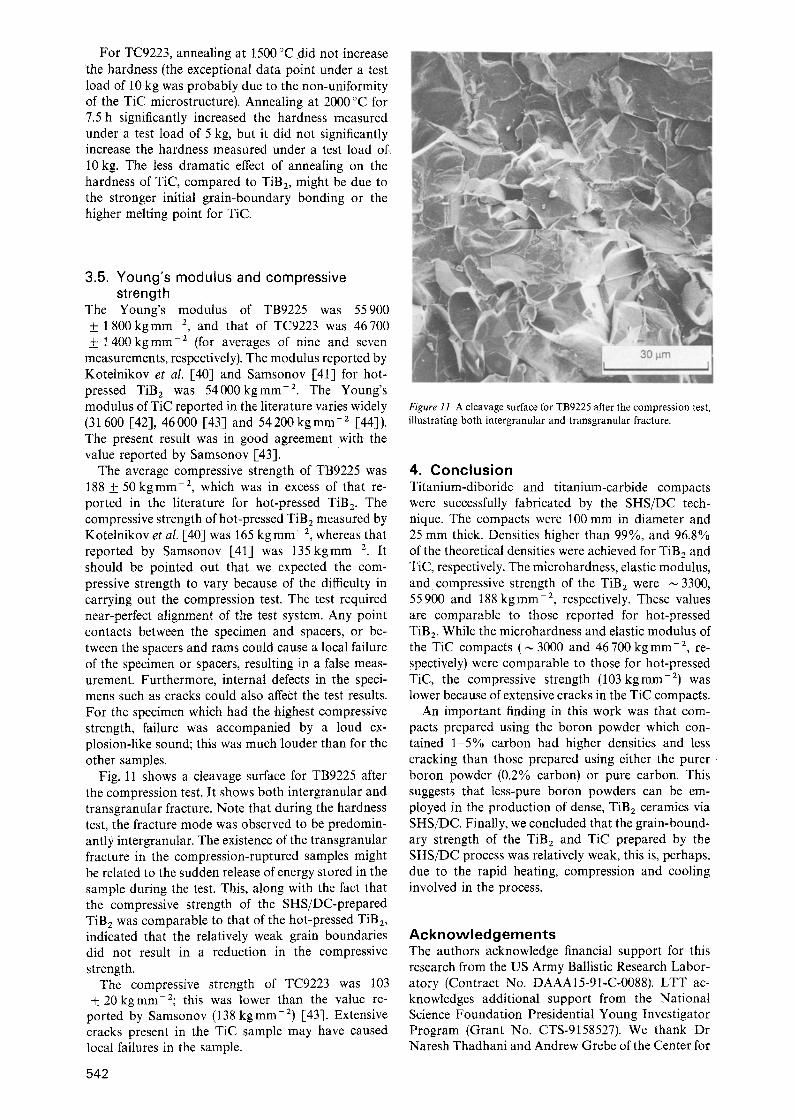
Fig. 11 shows a cleavage surface for TB9225 after the compression test. It shows both intergranular and transgranular fracture. Note that during the hardness test, the fracture mode was observed to be predomin- antly intergranular. The existence of the transgranular fracture in the compression-ruptured samples might be related to the sudden release of energy stored in the sample during the test. This, along with the fact that the compressive strength of the SHS/DC-prepared TiB 2 was comparable to that of the hot-pressed TiB 2, indicated that the relatively weak grain boundaries did not result in a reduction in the compressive strength.
The compressive strength of TC9223 was 103 -t-20 kgmm-2; this was lower than the value re-
ported by Samsonov (138 kgmm -2) [43]. Extensive cracks present in the TiC sample may have caused local failures in the sample.
542
Figure 11 A cleavage surface for TB9225 after the compression test, illustrating both intergranular and transgranular fracture.
4. Conclusion Titanium-diboride and titanium-carbide compacts were successfully fabricated by the SHS/DC tech- nique. The compacts were 100 mm in diameter and 25 mm thick. Densities higher than 99%, and 96.8% of the theoretical densities were achieved for TiB 2 and TiC, respectively. The microhardness, elastic modulus, and compressive strength of the TiB 2 were ~ 3300, 55900 and 188 kgmm -2, respectively. These values are comparable to those reported for hot-pressed TiB 2. While the microhardness and elastic modulus of the TiC compacts (~ 3000 and 46 700 kg mm-2, re- spectively) were comparable to those for hot-pressed TiC, the compressive strength (103kgmm -2) was lower because of extensive cracks in the TiC compacts.
An important finding in this work was that com- pacts prepared using the boron powder which con- tained 1-5% carbon had higher densities and less cracking than those prepared using either the pure r boron powder (0.2% carbon) or pure carbon. This suggests that less-pure boron powders can be em- ployed in the production of dense, TiB2 ceramics via SHS/DC. Finally, we concluded that the grain-bound- ary strength of the TiB 2 and TiC prepared by the SHS/DC process was relatively weak, this is, perhaps, due to the rapid heating, compression and cooling involved in the process.
Acknowledgements The authors acknowledge financial support for this research from the US Army Ballistic Research Labor- atory (Contract No. DAAA15-91-C-0088). LTT ac- knowledges additional support from the National Science Foundation Presidential Young Investigator Program (Grant No. CTS-9158527). We thank Dr Naresh Thadhani and Andrew Grebe of the Center for

Explosive Technologies Research at New Mexico Tech. for preparation of the compacts, and Dr Andrus Niiler of the Ballistic Research Laboratory for valu- able discussions.
R~ferences 1. M. L. WILKINS, C. F. CLINE alad C. A. HONODEL,
Fourth Progress Report of the Light Armor Program, UCRL- , 50694, Lawrence Radiation Laboratory, University of California, Livermore (1969).
2. M.L . WlLKINS, R. L. L A N D I N G H A M , C. A. HONODEL, Fifth Progress Report of the Light Armor Program, UCRL- 50980, Lawrence Radiation Laboratory, University of California, Livermore (1971).
3. G .V . SAMSONOV and B. A. KOVENSKAYA, in "Boron and refractory borides", edited by V. I. Matkovich (Springer- Verlag, Berlin, 1977) p. 5.
4. L .E . TOTH, "Transit ion metal carbides and nitrides" (Aca- demic Press, New York, 1971).
5. E . K . STORMS, "The refractory carbides" (Academic Press, New York, 1967).
6. O. YAMADA, Y. M I Y A M O T O and M. K O I Z U M I , Amer. Ceram. Bull. 64 (1985) 319.
7. J . B . HOLT, D. D. K I N G M A N and G. M. BIANCHINI, Mater. Sci. Engng. 71 (1085) 321.
8. R .W. RICE and W. J. M c D O N O U G H , J. Amer. Ceram. Soc. 68 (1985) C-122.
9. J .B. HOLT and Z. A. MUNIR, J. Mater. Sci. 21 (1986) 251. 10. K. HIRAO, Y. M IYAM OT O and M. K O I Z U M I , Yogyo-
Kyokai-Shi 95 (1987) 23. 11. Z .A . MUNIR, Amer. Ceram. Bull. 67 (1988) 342. 12. S .D . D U N M E A D , D. W. READY and C. E. SEMLER, J.
Amer. Ceram. Soc. 72 (1989) 2318. t3. z . A . M U N I R and U. A N S E L M I - T A M B U R I N I , Mater. ScL
Reports 3 (1989) 277. 14. Y. CHOI, M. E. MULLINS, K. WlJAYATILLEKE and
J. K. LEE, High Temp. Tech. 8 (1990) 227. 15. J. TRAMBUKIS and Z. A. MUNIR, J. Arner. Ceram. Soc. 73
(1990) 1240. 16. M. E S L A M L O O - G R A M I and Z. A. MUNIR, ibid. 73 (1990)
1235. 17. C. C. AGRAFIOTIS , J. LIS, J. A. PUSZYNSKI and
V. HLAVACEK, ibid. 73 (1990) 3514. 18. H .C . YI and J. J. MOORE, J. Mater. Sci. 25 (1990) 1159. 19. S .C. DEEVI, ibid. 26 (1991) 2662. 20. R .W. RICE, ibid. 26 (1991) 6533. 21. J. Z E N G a n d Y. MIYAMOTO, J. Amer. Ceram. Soc. 74(1991)
2197. 22. M.A . RILEY and A. NIILER, Memorandum Report BRL-
MR-3574, US Army Ballistic Research Laboratory, Aberdeen Proving Ground, M D (1987).
23. A. NIILER, L. J. KECSKES, T. KOTTKE, P. H. NETHER- WOOD jr. and R. F. BENCK, Technical Report BRL-TR- 2951, US Army Ballistic Research Laboratory, Aberdeen Proving Ground, M D (1988).
24. A. NIILER, L. J. KECSKES and T. KOTTKE, in "Com- bustion and plasma synthesis of high temperature materials", edited by Z. A. Munir and J. B. Birch (VCH, New York, 1990) p. 309.
25. L.J . KECSKES, R. F. BENCK and P. H. N E T H E R W O O D , J. Amer. Ceram. Soc. 73 (1990) p. 383.
26 . H. A. GREBE, A. ADVANI, N. N. THADHANI and T. K O TT K E, private communication.
27. A. H. ADVANI, N. N. THADHANI , H. A. GREBE, R. HEAPS, C. C O F F I N and T. KOTTKE, J. Mater. Sci. 27 (1992) 3309.
28. H.A. GREBE, PhD thesis, New Mexico Tech, Socorro, New Mexico (1993).
29. O. YAMADA, Y. MIYAMOTO and M. K o I Z U M I , J. Amer. Ceram. Soc. 70 (1987) C-206.
30. J .C . LaSALVIA, L. W. MEYER and M. A. MEYERS, ibid. 75 (1992) 592.
31. L . J . KECSKES and A. NIILER, ibid. 72 (1989) 655. 32. D .B . MIRACLE and H. A. LIPSITT, ibid. 66 (1983) 592. 33. M . I . MENDELSON, ibid. 52 (1969) 443. 34. C. KITTEL,"In t roduct ion to solid state physics" (John Wiley,
New York, 1953). 35. J .R . RAMBERG and W. S. WILLIAMS, J. Mater. Sci. 22
(1987) 1815. 36. T .B. MASSALAKI (editor-in chief) "Binary alloy phase dia-
grams", Vol. 1 (American Society for Metals, Metals Park, Ohio, 1986). �9
37. I. J. McCOLM, "Ceramic hardness" (Plenum Press, New York, 1990).
38. E .R. HONAK, Thesis, Tech. Hochsch. Graz (1951)�9 39. R. K I E F F E R a n d F. KOLBL, Powder Metall. Bull. 4(1949) 4. 40. R.B. K O T E L N I K O V , S. N. BASHLYKOV, Z. G. GALIAC-
BAROV and A. J. KASHTANOV, "Especially high melting elements and compounds" (Isdatel'stvo Metallurgija, Moscow, 1969).
41. G. V. SAMSONOV, "Refractory compounds" (Moscow, Metallurgizdat, 1963).
42. W . D . KINGERY, H, K. BOWEN and D. R. U H L M A N N , "Introduction to ceramics" (John Wiley, New York, 1976).
43. G. V. SAMSONOV, "Plenum press handbook of high- temperature materials", No. 2, Properties Index (Plenum Press, New York, 1962).
44. C. H. McMURTRY, W. D. G. BOECKER, S. G. SESHADRI, J. S. ZANGHI and J. E. GARNIER, Amer. Ceram. Bull. 66 (1987) 325.
Received 24 April and accepted 9 July 1993.
543