and ParticipativeAxiomatic Design Processin complex ...
14
Iterative and Participative Axiomatic Design Process in complex mechanical assemblies: case study on fusion engineering G. Di Gironimo · A. Lanzotti · D. Marzullo · G. Esposito · D. Carfora · M. Siuko Abstract The present paper proposes a structured Product Development Lifecycle (PDL) model to deal with the concept design stage of complex assemblies. The proposed method provides a systematic approach to design, aimed to improve requirements management, project management and com- munication among stakeholders as well as to avoid project failures reducing project development time. This research also provides suggestions and recommendations for utiliz- ing different analysis, synthesis and assessment method- ologies along with the proposed approach. The process developed, named Iterative and Participative Axiomatic Design Process (IPADeP), is consistent with ISO/IEC 15288: 2008 – “Systems and software engineering”, and INCOSE Systems engineering handbook. It is an iterative and incre- mental design process, participative and requirements driven, based on the theory of Axiomatic Product Development Life- cycle (APDL). IPADeP provides a systematic methodology in which, starting from a set of experts’ assumptions, a num- ber of conceptual solutions are generated, analysed and eval- uated. Based on the results obtained, new iterations can be performed for each level of decomposition while product requirements are refined. In this paper, we applied IPADeP to the initial phase of conceptual design activities for DEMO G. Di Gironimo · A. Lanzotti · D. Marzullo · G. Esposito Industrial Engineering Department (DII), ENEA/CREATE, University of Naples “Federico II”, Piazzale Tecchio 80, 80125 Napoli, Italy D. Carfora · M. Siuko VTT Systems Engineering, Tekniikankatu 1, 33720 Tampere, Finland G. Di Gironimo (B ) Dipartimento di Ingegneria Industriale, Unversità degli Studi di Napoli “Federico II”, Piazzale Tecchio 80, 80125 Napoli, Italy e-mail: [email protected] divertor-to-vacuum vessel locking system in order to propose new innovative solutions. Keywords Systems engineering · Concept design · Axiomatic Design · Fuzzy-AHP · DEMO divertor locking system 1 Introduction Engineering product development is becoming increasingly knowledge-intensive and collaborative. The stakeholders and partners involved in product development are increasing var- ious and geographically dispersed, so more and more atten- tion is paid to global cooperation during the design phase and outsourcing the manufacturing processes [1]. In this context, so-called principle-based methods have gained popularity because they provide a general scientific basis that supports design decisions. In particular, studies of the early design stages dealing with a higher level of abstraction have recently attracted increasing attention from academia [2]. Recent researches have shown that the top cause of trou- bled projects regards the early design stage and is related to the requirements that sometimes are unclear, with lack of agreement and/or priority, contradictory, ambiguous and imprecise [3]. These situations are common at the begin- ning of the design process (especially before detailed design as defined by Pahl and Beitz [4]), due to numerous experts involved in integrated and collaborative design [5]. The PDL models should support this phase identifying correct and complete requirements and verifying the design starting from the very early stages in order to reduce the cost and schedule and to satisfy the customer since 80% of the products total cost is committed during the concept devel- opment phase [6]. Requirements management concerns the 1
Transcript of and ParticipativeAxiomatic Design Processin complex ...
Iterative and Participative Axiomatic Design Process in complexmechanical assemblies: case study on fusion engineering
G. Di Gironimo · A. Lanzotti · D. Marzullo ·G. Esposito · D. Carfora · M. Siuko
Abstract The present paper proposes a structured ProductDevelopmentLifecycle (PDL)model to dealwith the conceptdesign stage of complex assemblies. The proposed methodprovides a systematic approach to design, aimed to improverequirements management, project management and com-munication among stakeholders as well as to avoid projectfailures reducing project development time. This researchalso provides suggestions and recommendations for utiliz-ing different analysis, synthesis and assessment method-ologies along with the proposed approach. The processdeveloped, named Iterative and Participative AxiomaticDesign Process (IPADeP), is consistentwith ISO/IEC15288:2008 – “Systems and software engineering”, and INCOSESystems engineering handbook. It is an iterative and incre-mental design process, participative and requirements driven,based on the theory ofAxiomatic Product Development Life-cycle (APDL). IPADeP provides a systematic methodologyin which, starting from a set of experts’ assumptions, a num-ber of conceptual solutions are generated, analysed and eval-uated. Based on the results obtained, new iterations can beperformed for each level of decomposition while productrequirements are refined. In this paper, we applied IPADePto the initial phase of conceptual design activities for DEMO
G. Di Gironimo · A. Lanzotti · D. Marzullo · G. EspositoIndustrial Engineering Department (DII), ENEA/CREATE,University of Naples “Federico II”, Piazzale Tecchio 80,80125 Napoli, Italy
D. Carfora ·M. SiukoVTT Systems Engineering, Tekniikankatu 1, 33720 Tampere,Finland
G. Di Gironimo (B)Dipartimento di Ingegneria Industriale, Unversità degli Studi di Napoli“Federico II”, Piazzale Tecchio 80, 80125 Napoli, Italye-mail: [email protected]
divertor-to-vacuumvessel locking system in order to proposenew innovative solutions.
Keywords Systems engineering · Concept design ·Axiomatic Design · Fuzzy-AHP · DEMO divertor lockingsystem
1 Introduction
Engineering product development is becoming increasinglyknowledge-intensive and collaborative. The stakeholders andpartners involved in product development are increasing var-ious and geographically dispersed, so more and more atten-tion is paid to global cooperation during the design phase andoutsourcing the manufacturing processes [1]. In this context,so-called principle-based methods have gained popularitybecause they provide a general scientific basis that supportsdesign decisions. In particular, studies of the early designstages dealingwith a higher level of abstraction have recentlyattracted increasing attention from academia [2].
Recent researches have shown that the top cause of trou-bled projects regards the early design stage and is relatedto the requirements that sometimes are unclear, with lackof agreement and/or priority, contradictory, ambiguous andimprecise [3]. These situations are common at the begin-ning of the design process (especially before detailed designas defined by Pahl and Beitz [4]), due to numerous expertsinvolved in integrated and collaborative design [5].
The PDL models should support this phase identifyingcorrect and complete requirements and verifying the designstarting from the very early stages in order to reduce the costand schedule and to satisfy the customer since 80% of theproducts total cost is committed during the concept devel-opment phase [6]. Requirements management concerns the
1

sidering that the requirements will be refined and completedduring the process. It was developed according to the designprocess roadmap proposed by Tate andNordlund (1996), andit is based on the theory of Axiomatic product developmentlifecycle (APDL) [8] as regards the phases of requirementsmanagement and architectural development of conceptualsolutions. Fuzzy AHP is used as a tool for decision-making.In order to test IPADeP methodology a case study concern-ing the design of fusion reactors (Tokamaks) was taken intoaccount. Indeed the development of tokamak sub-systemshas to take into account interface, structural and functionalrequirements and multiphysics issues that can be completelyknown only during the development of the process.
2 General background
A design process converts a need, a required functionality,into a product satisfying that need. Such a process is quitecomplex and requires designer’s initiative, creativity and theavailability of awide rangeof skills,methodologies and expe-rience in attaining a solution. Design proceeds from abstractand qualitative ideas to quantitative descriptions, and it is aniterative process by nature: new information is generated ateach step and it is necessary to evaluate the results in termsof the preceding step [9]. Suh [10] sees design as a continu-ous interplay between the requirements (what) the designerwants to achieve and how the designer wants to achievethese requirements. Many engineers have been designingtheir products intuitively, based on their experience, involv-ing much trial and error. This approach is very unsystematic(i.e., lacking of a definite plan) and overly time consuming.For this reason, experience gained from such practices cannotbe easily reapplied to other similar issues. Although experi-ence is important since it generates knowledge and infor-mation about practical design, experiential knowledge aloneis not enough, as it is not always reliable, especially whenthe context of the application changes. Experience must besupported by systematic knowledge of design [10]. Designhas always benefited from creativity, but this process mustbe augmented by systematically amplifying human capabil-ity to understand cognitive behaviour and by the develop-ment of scientific foundations for design methods [11]. Inrecent years, many researches have shown the importance ofstructured and scientifically based theories and methods forproduct (and process) design and development, in order toreduce development time, reduce product costs and increasevalue. As stated by Tate, Nordlund [12], an effective prod-uct development process, supported by scientifically vali-dated design theories and tools, is becoming an increasinglyuseful asset in industry for reducing lead times and costsas well as for improving quality. Some design methodolo-gies available in literature deal with most of PDL activities
collection, analysis, and validation of requirements with all the communications and negotiations inherent in the working process. Without establishing detailed requirement, the risk of project failure would be unacceptably high. For this reason it is extremely important to make a systematic approach to design since the early phase of product development process. Indeed during this phase the loss caused by selecting wrong design solutions can afflict the whole development processes and is hard to recover later [2].
The traditional practice of systems engineering manage-ment involves the determination of requirements at or near the beginning of a system development project. All subse-quent steps are dependent upon the completeness, accuracy and specificity of these requirements. Within the context of ISO/IEC 15288:2008 and INCOSE Systems engineering handbook [7], requirements are specifically mentioned in two of the technical processes and they are drivers for many of the system life cycle processes. Depending on the system development model, requirements capture may be done nom-inally once near the beginning of the development cycle or, as for agile methods, be a continuous activity. When apply-ing systems engineering, there is near unanimous agreement that successful projects depend on meeting the needs and requirements of the customers. Without establishing detailed requirements, the risk of project failure would be unaccept-ably high.
Requirement elicitation is an iterative activity and bene-fits from continuous communication and validation with the customer. No design can be completed before establishment of the System Requirements Documents (SRD) reflecting all relevant design inputs. In complex contests, with a number of stakeholders involved, requirements are not static and one reason for that is the continuous learning and better under-standing of the design concept and its environment during design process. During the initial stages of conceptual design it may not be needed to establish all requirements; however, the necessary design criteria should be fixed before starting the related level of design. Moreover, constant changes occur to the systems during the early phase of conceptual stage.
Generally, in the development of complex mechanical sys-tems the design process starts when the requirements are not completely defined from the beginning, but the information from the various partners working at the project will come in during the design activities.
In order to overcome these difficulties, in this paper we propose a design process for drafting solutions in an “incomplete requirements environment”. In this kind of approach, the information will be completed during the design development. The process, named Iterative and Par-ticipative Axiomatic Design Process (IPADeP), is an iterative and incremental, participative process, requirements driven. It has been developed so as to minimize the risks related to the uncertainty and incompleteness of the requirements, and con-
2
whereas other methodologies deal with the process of creat-ing a solution to a stated need. According to [10] and [12]the design activities should start from the knowledge of the“customers’ needs” and the definition of the requirements.Prior to proceed with the physical implementation, a com-plete, unambiguous, consistent, understandable, traceable,and modifiable set of requirements is needed [7]. However,in the early conceptual design stage the requirements for theproject could be continuously provided from different actorsinvolved in the design activities and completed during thedesign process.
Many types of systems have proven to be resistant torequirements determination. As a consequence, applicationof traditional management processes does not adequatelyassure operational effectiveness [13]. Several authors havedealt with requirements change and uncertainty in engi-neering [14], and according to [15] the later changes occurin the design process, the more people is affected. More-over, the cost of implementing a change increases on aver-age by a factor of 10 between each phase of the designprocess [16,17]. Companies usually integrate their customersin the design process and use instruments, such as QualityFunction Deployment (QFD) [18], to build up a clear pic-ture of their requirements to avoid later changes [19]. A thesame time, companies apply the classical systems engineer-ing V-model and test products virtually as soon as possi-ble [15]. To generate Functional Requirements (FRs) andconcepts at an abstract level QFD is an effective tool [20],but it can be difficult to select and specify design alterna-tives at a more detailed level [21]. On the other hand, to pro-duce high-quality design alternatives at a parametric levelTaguchi’s robust design principles [22,23] have been widelyused, but according to Thielman, Ge [21] is not clear howto apply Taguchi’s principles when the generation of con-cepts from qualitative functionality descriptions is required.An approach based on Axiomatic Design (AD) simplifies theorganization of complex design processes; it uses axioms togenerate and evaluate design alternatives, combining a map-ping and decomposition process (zigzagging) [10,11]. Theapplication of the AD theory in a nuclear reactor system [21]demonstrated that this methodological approach representsa viable method for large-scale engineering systems devel-opment. AD deals with most of PDL activities, but it doesnot support the whole PDL [24]. To provide a systematicapproach for PDL activities and management, and to ensurethat all the activities in the PDL are aligned with the require-ments at all times, Gumus et al. [8] proposed a new model(APDL) based on the systematic nature of AD. APDL isbuilt as a V-shaped process to develop the initial design witha top-down approach, while producing and testing the prod-uct with a bottom-up approach [8]. APDL covers the wholeproduct lifecycle including early factors that affect the entirecycle. APDL provides useful tools to address the problem of
requirements traceability and design solutions creations but,in some aspects, it needs to be enhanced and better definedin order to provide a clear and systematic approach to designactivity in the early conceptual design phase. The methodol-ogy here presented (IPADeP) aims to improve these aspects,proposing an incremental design process that deals with thechange and completion of the requirements typical duringthe pre-conceptual and conceptual phases.
3 Materials and methods
The methodology described below has been developed inorder to minimize the risks related to the uncertainty andincompleteness of the requirements, and considering thatthe requirements will be refined and completed during theprocess. The process, named Iterative and Participative ADProcess (IPADeP), is an iterative, incremental, participativeand requirements driven process. It was developed accord-ing to the design process roadmap proposed by Tate, Nord-lund [12], and it is based on the theories of AxiomaticDesign (AD) [10,11], Axiomatic Product Development Life-cycle (APDL) [25] and Fuzzy Analytic Hierarchy Process(AHP) [26,27] as a tool for decision-making.
3.1 Axiomatic Design
The AD method provides a systematic and logical methodfor deriving, documenting and optimizing designs. Further-more it helps avoid traditional design-build-test-redesigncycles for design solution search and for determining thebest design among those proposed. An extended explanationof the method is contained in [10] and [11]. There are fourmain items in AD: (I) domains, (II) hierarchies, (III) zigzag-ging and (IV) design axioms. Domains, which are four, aregeneralized as customer domain, functional domain, phys-ical domain and the process domain. Design elements areassociated with each domain. Elements within each domainare:CustomerNeeds (CNs); FunctionalRequirements (FRs);Design Parameters (DPs) and Process Variables (PVs). Foreach pair of adjacent domains, the domain on the left repre-sents “what we want to achieve”, while the domain on theright represents the design solution of “how we propose toachieve it”. Therefore, the design process can be defined asmapping from the “what” domain to the “how” domain. FRsandDPs are developed to provide enough design informationat the conceptual level and are decomposed until the designcan be implemented. The decomposition is performed byzigzagging between the domains, starting from the “what”domain to the “how” domain. FRs and DPs hierarchies areestablished to represent the product design structure through-out the decomposition process. There are two axioms in AD,to support analysis, which can be stated as follows [11]:
3
• The independence axiom (first axiom): Maintain theindependence of functional requirements. It means thateach one of the FRs can be satisfied by its correspondingDP without affecting the other FRs;
• The information axiom (second axiom): Minimize theinformation content of the design. The purpose is to findthe design with the highest probability of achieving theFRs.
The APDLmodel proposes a V-shaped process to developthe detail design with a top-down approach, and to produceand test the product with a bottom-up approach as shown inFig. 1.
Once the FRs and the ICs are derived, they should beanalysed to develop the system FRs, DPs, and SCs tripletthat states the system objective, the proposed system designand the proposed SC. Then, the design decomposition andzigzagging process starts. Since the initial FRs can be at dif-ferent levels of detail, they should be mapped to the FRs/DPshierarchy during the decomposition process. Full integra-tion of documentation as well as traceability throughout thedevelopment lifecycle should be provided. It is important todefine standard templates for domain entities and for CNs,FRs, CTCs, and FTCs. The templates for documenting thedomain entities and the mapping matrix have been presentedby Gumus [25].
3.3 Iterative and participative axiomatic design process(IPADeP)
IPADeP is an iterative and incremental design process, par-ticipative and requirements driven. It provides a robust struc-ture and systematic thinking to support design activities inthe early conceptual design stage of large and complex sys-tems. In this stage, even if the information are not yet com-pleted, the requirements for the project will come in fromthe other actors involved in the project during the designactivities (i.e. interface requirements). It is needed to startthe design process in order to reduce lead-time basing on theassumptions that it is possible to do thanks to experiencesin previous similar projects. IPADeP could be seen as anenhancement of the top-down side of the APDL V-model tobetter address the early conceptual design phase. It highlightsthe iterative nature of the design activities; for each level ofdecomposition iteration is performed, and from the seconditeration also new information could come in the processfrom the stakeholders. The IPADeP flowchart is presentedin Fig. 2.
The process starts with a first iteration that correspondsto levels 0-1 of decomposition. At this level the needs ofthe system are known but there is not yet a set of definedrequirements. To start the process, brainstorming sessionsbetween experts and stakeholders is performed in order todefine few generic needs and then map these needs in theinitial FRs and ICs. To document and trace the mappingprocess, according to the APDL method [8], we have usedtheRequirementMatrix and aConstraintMatrix templates byGumus [25]. Theoutput of this phase is defined in thiswork asFRs to maintain the definition used in AD. However, accord-ing with Kossiakoff et al. [28], we should not yet call thisdescription a set of requirements, though they are certainlythe forerunner of what will be defined as official require-
During the mapping process (for example, mapping from FRs in the functional domain to DPs in the physical domain), the designer should take the correct design decisions using the independence axiom. When several designs that satisfy the independence axiom are available, the information axiom can be used to select the best design. Designers apply the independence axiom by using design matrixes that repre-sent the mapping between the domains. The set of FRs that define the specific design goals constitutes a vector FRs in the functional domain. Similarly, the set of DPs in the physi-cal domain that describe the design solution also constitutes a vector DPs. The relationship between the two vectors can be written as: {FRs } = [A] {DPs }, where [A] is the design matrix that characterizes the nature of the mapping. Design matrixes and system architecture highlight the relationships between the FRs, DPs and Input Constraints (ICs); they can be used to evaluate the impact of proposed design changes as well as FR and constraint changes.
3.2 Axiomatic product development lifecycle
The APDL model utilizes the systematic nature of the AD method in order to provide a systematic approach for Product Development Lifecycle (PDL) activities and management, and provide an iterative and incremental way for a team of trans-disciplinary members to approach holistic product development. The APDL improves the AD in the area of domain entity description and management and takes the AD method one step further to support the test domain of the PDL [8].
One new domain and four new characteristic vectors are added to the existing AD domains and characteristic vec-tors. The methodology supports different development life-cycle activities, such as requirements and change manage-ment throughout the whole PDL. A characteristic vector for the System Components (SCs), that are the physical entities that provide the design solution stated in the DPs, is defined in the Physical Domain. The SCs hierarchy represents the phys-ical architecture of the system. The Test Domain is added to the existing AD domains, and it contains the Component Test Cases (CTCs), that are used to verify the corresponding com-ponent that satisfies the allocated FRs, and the Functional Test Cases (FTCs).
4
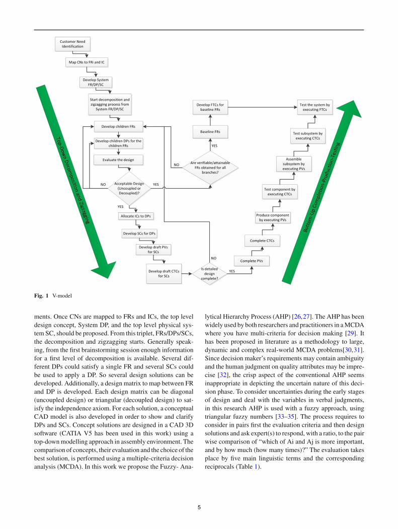
Fig. 1 V-model
ments. Once CNs are mapped to FRs and ICs, the top leveldesign concept, System DP, and the top level physical sys-tem SC, should be proposed. From this triplet, FRs/DPs/SCs,the decomposition and zigzagging starts. Generally speak-ing, from the first brainstorming session enough informationfor a first level of decomposition is available. Several dif-ferent DPs could satisfy a single FR and several SCs couldbe used to apply a DP. So several design solutions can bedeveloped. Additionally, a design matrix to map between FRand DP is developed. Each design matrix can be diagonal(uncoupled design) or triangular (decoupled design) to sat-isfy the independence axiom. For each solution, a conceptualCAD model is also developed in order to show and clarifyDPs and SCs. Concept solutions are designed in a CAD 3Dsoftware (CATIA V5 has been used in this work) using atop-downmodelling approach in assembly environment. Thecomparison of concepts, their evaluation and the choice of thebest solution, is performed using a multiple-criteria decisionanalysis (MCDA). In this work we propose the Fuzzy- Ana-
lytical Hierarchy Process (AHP) [26,27]. The AHP has beenwidely used by both researchers and practitioners in aMCDAwhere you have multi-criteria for decision making [29]. Ithas been proposed in literature as a methodology to large,dynamic and complex real-world MCDA problems[30,31].Since decision maker’s requirements may contain ambiguityand the human judgment on quality attributes may be impre-cise [32], the crisp aspect of the conventional AHP seemsinappropriate in depicting the uncertain nature of this deci-sion phase. To consider uncertainties during the early stagesof design and deal with the variables in verbal judgments,in this research AHP is used with a fuzzy approach, usingtriangular fuzzy numbers [33–35]. The process requires toconsider in pairs first the evaluation criteria and then designsolutions and ask expert(s) to respond, with a ratio, to the pairwise comparison of “which of Ai and Aj is more important,and by how much (how many times)?” The evaluation takesplace by five main linguistic terms and the correspondingreciprocals (Table 1).
5
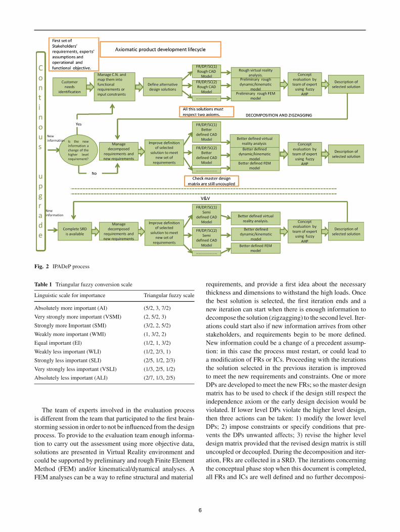
Fig. 2 IPADeP process
Table 1 Triangular fuzzy conversion scale
Linguistic scale for importance Triangular fuzzy scale
Absolutely more important (AI) (5/2, 3, 7/2)
Very strongly more important (VSMI) (2, 5/2, 3)
Strongly more Important (SMI) (3/2, 2, 5/2)
Weakly more important (WMI) (1, 3/2, 2)
Equal important (EI) (1/2, 1, 3/2)
Weakly less important (WLI) (1/2, 2/3, 1)
Strongly less important (SLI) (2/5, 1/2, 2/3)
Very strongly less important (VSLI) (1/3, 2/5, 1/2)
Absolutely less important (ALI) (2/7, 1/3, 2/5)
requirements, and provide a first idea about the necessarythickness and dimensions to withstand the high loads. Oncethe best solution is selected, the first iteration ends and anew iteration can start when there is enough information todecompose the solution (zigzagging) to the second level. Iter-ations could start also if new information arrives from otherstakeholders, and requirements begin to be more defined.New information could be a change of a precedent assump-tion: in this case the process must restart, or could lead toa modification of FRs or ICs. Proceeding with the iterationsthe solution selected in the previous iteration is improvedto meet the new requirements and constraints. One or moreDPs are developed to meet the new FRs; so the master designmatrix has to be used to check if the design still respect theindependence axiom or the early design decision would beviolated. If lower level DPs violate the higher level design,then three actions can be taken: 1) modify the lower levelDPs; 2) impose constraints or specify conditions that pre-vents the DPs unwanted affects; 3) revise the higher leveldesign matrix provided that the revised design matrix is stilluncoupled or decoupled. During the decomposition and iter-ation, FRs are collected in a SRD. The iterations concerningthe conceptual phase stop when this document is completed,all FRs and ICs are well defined and no further decomposi-
The team of experts involved in the evaluation process is different from the team that participated to the first brain-storming session in order to not be influenced from the design process. To provide to the evaluation team enough informa-tion to carry out the assessment using more objective data, solutions are presented in Virtual Reality environment and could be supported by preliminary and rough Finite Element Method (FEM) and/or kinematical/dynamical analyses. A FEM analyses can be a way to refine structural and material
6
tion is needed. At this point all requirements are verifiable,attainable and approved by stakeholders and verification andvalidation activities can be performed to arrive at the firstlifecycle decision gate: Conceptual Design Review.
4 Results of IPADeP application to a fusion engineeringcase study: conceptual design of the DEMOdivertor-to-vacuum vessel locking system
Within the activities on fusion research, while ITER reactoris under construction, concept design activities have startedfor the DEMOnstration fusion power plant (DEMO), thetokamak that will demonstrate the feasibility of energy pro-duction from nuclear fusion and will mark the very firststep of fusion power into the energy market by supplyingelectricity to the grid [36,37]. In this work IPADeP wasapplied to the initial phase of conceptual design activitiesfor a tokamak subsystem, DEMO divertor-to-vacuum ves-sel locking system, to propose new innovative solutions thatcould overcome the difficulties in applying the ITER princi-ples to DEMO [38,39]. Due to the lack and the uncertainlyof the requirements in this early conceptual design stage, wecovered the first interactions of the framework (decompo-sition level 0-1), and obtained an innovative concept to bedeveloped in more details as information will be detailed.
4.1 Identification of customer needs
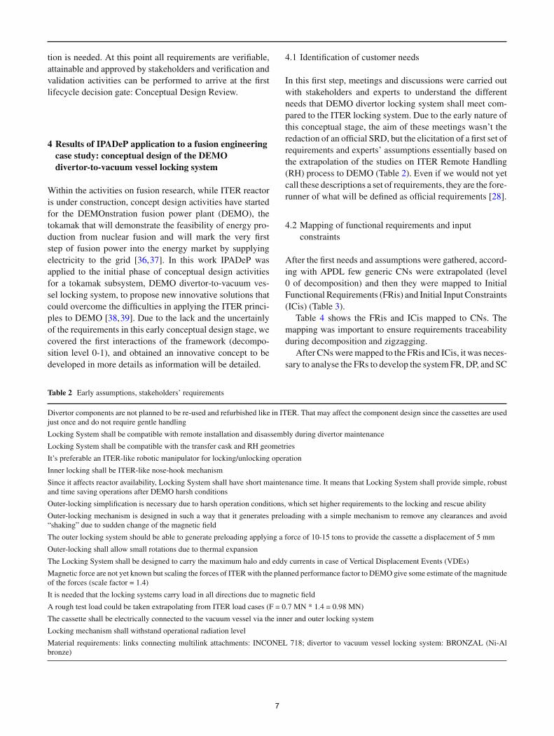
In this first step, meetings and discussions were carried outwith stakeholders and experts to understand the differentneeds that DEMO divertor locking system shall meet com-pared to the ITER locking system. Due to the early nature ofthis conceptual stage, the aim of these meetings wasn’t theredaction of an official SRD, but the elicitation of a first set ofrequirements and experts’ assumptions essentially based onthe extrapolation of the studies on ITER Remote Handling(RH) process to DEMO (Table 2). Even if we would not yetcall these descriptions a set of requirements, they are the fore-runner of what will be defined as official requirements [28].
4.2 Mapping of functional requirements and inputconstraints
After the first needs and assumptions were gathered, accord-ing with APDL few generic CNs were extrapolated (level0 of decomposition) and then they were mapped to InitialFunctional Requirements (FRis) and Initial Input Constraints(ICis) (Table 3).
Table 4 shows the FRis and ICis mapped to CNs. Themapping was important to ensure requirements traceabilityduring decomposition and zigzagging.
After CNsweremapped to the FRis and ICis, it was neces-sary to analyse the FRs to develop the system FR, DP, and SC
Table 2 Early assumptions, stakeholders’ requirements
Divertor components are not planned to be re-used and refurbished like in ITER. That may affect the component design since the cassettes are usedjust once and do not require gentle handling
Locking System shall be compatible with remote installation and disassembly during divertor maintenance
Locking System shall be compatible with the transfer cask and RH geometries
It’s preferable an ITER-like robotic manipulator for locking/unlocking operation
Inner locking shall be ITER-like nose-hook mechanism
Since it affects reactor availability, Locking System shall have short maintenance time. It means that Locking System shall provide simple, robustand time saving operations after DEMO harsh conditions
Outer-locking simplification is necessary due to harsh operation conditions, which set higher requirements to the locking and rescue ability
Outer-locking mechanism is designed in such a way that it generates preloading with a simple mechanism to remove any clearances and avoid“shaking” due to sudden change of the magnetic field
The outer locking system should be able to generate preloading applying a force of 10-15 tons to provide the cassette a displacement of 5 mm
Outer-locking shall allow small rotations due to thermal expansion
The Locking System shall be designed to carry the maximum halo and eddy currents in case of Vertical Displacement Events (VDEs)
Magnetic force are not yet known but scaling the forces of ITERwith the planned performance factor to DEMO give some estimate of the magnitudeof the forces (scale factor = 1.4)
It is needed that the locking systems carry load in all directions due to magnetic field
A rough test load could be taken extrapolating from ITER load cases (F = 0.7 MN * 1.4 = 0.98 MN)
The cassette shall be electrically connected to the vacuum vessel via the inner and outer locking system
Locking mechanism shall withstand operational radiation level
Material requirements: links connecting multilink attachments: INCONEL 718; divertor to vacuum vessel locking system: BRONZAL (Ni-Albronze)
7
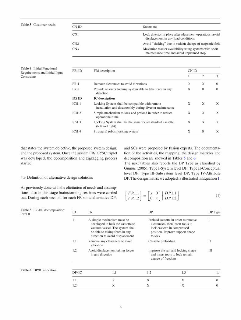
Table 3 Customer needsCN ID Statement
CN1 Lock divertor in place after placement operations, avoiddisplacement in any load conditions
CN2 Avoid “shaking” due to sudden change of magnetic field
CN3 Maximize reactor availability using systems with shortmaintenance time and avoid unplanned stop
Table 4 Initial FunctionalRequirements and Initial InputConstraints
FRi ID FRi description CN ID
1 2 3
FRi1 Remove clearances to avoid vibrations 0 X 0
FRi2 Provide an outer locking system able to take force in anydirection
X 0 0
ICi ID IC description
ICi1.1 Locking System shall be compatible with remoteinstallation and disassembly during divertor maintenance
X X X
ICi1.2 Simple mechanism to lock and preload in order to reduceoperational time
X X X
ICi1.3 Locking System shall be the same for all standard cassette(left and right)
X X X
ICi1.4 Structural robust locking system X 0 X
that states the system objective, the proposed system design,and the proposed system. Once the system FR/DP/SC tripletwas developed, the decomposition and zigzagging processstarted.
4.3 Definition of alternative design solutions
As previously done with the elicitation of needs and assump-tions, also in this stage brainstorming sessions were carriedout. During each session, for each FR some alternative DPs
and SCs were proposed by fusion experts. The documenta-tion of the activities, the mapping, the design matrixes anddecomposition are showed in Tables 5 and 6.The next tables also reports the DP Type as classified byGumus (2005): Type I-System level DP; Type II-Conceptuallevel DP; Type III-Subsystem level DP; Type IV-AttributeDP. The designmatrixwe adopted is illustrated in Equation 1.
{FR1.1FR1.2
}=
[x 00 x
]{DP1.1DP1.2
}(1)
Table 5 FR-DP decomposition:level 0
ID FR DP DP Type
1 A simple mechanism must bedeveloped to lock the cassette tovacuum vessel. The system shallbe able to taking force in anydirection to avoid displacement
Preload cassette in order to removeclearances, then insert tools tolock cassette in compressedposition. Improve support shapeto lock
I
1.1 Remove any clearances to avoidvibration
Cassette preloading II
1.2 Avoid displacement taking forcesin any direction
Improve the rail and locking shapeand insert tools to lock remaindegree of freedom
III
Table 6 DP/IC allocationDP\IC 1.1 1.2 1.3 1.4
1.1 X X X 0
1.2 X X X 0
8
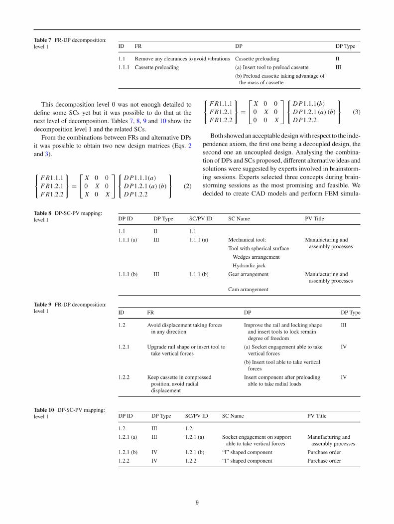
Table 7 FR-DP decomposition:level 1 ID FR DP DP Type
1.1 Remove any clearances to avoid vibrations Cassette preloading II
1.1.1 Cassette preloading (a) Insert tool to preload cassette III
(b) Preload cassette taking advantage ofthe mass of cassette
This decomposition level 0 was not enough detailed todefine some SCs yet but it was possible to do that at thenext level of decomposition. Tables 7, 8, 9 and 10 show thedecomposition level 1 and the related SCs.
From the combinations between FRs and alternative DPsit was possible to obtain two new design matrices (Eqs. 2and 3).
⎧⎨⎩
FR1.1.1FR1.2.1FR1.2.2
⎫⎬⎭ =
⎡⎣ X 0 00 X 0X 0 X
⎤⎦
⎧⎨⎩
DP1.1.1(a)
DP1.2.1 (a) (b)DP1.2.2
⎫⎬⎭ (2)
⎧⎨⎩
FR1.1.1FR1.2.1FR1.2.2
⎫⎬⎭ =
⎡⎣ X 0 00 X 00 0 X
⎤⎦
⎧⎨⎩
DP1.1.1(b)DP1.2.1 (a) (b)DP1.2.2
⎫⎬⎭ (3)
Both showed an acceptable designwith respect to the inde-pendence axiom, the first one being a decoupled design, thesecond one an uncoupled design. Analysing the combina-tion of DPs and SCs proposed, different alternative ideas andsolutions were suggested by experts involved in brainstorm-ing sessions. Experts selected three concepts during brain-storming sessions as the most promising and feasible. Wedecided to create CAD models and perform FEM simula-
Table 8 DP-SC-PV mapping:level 1 DP ID DP Type SC/PV ID SC Name PV Title
1.1 II 1.1
1.1.1 (a) III 1.1.1 (a) Mechanical tool: Manufacturing andassembly processesTool with spherical surface
Wedges arrangement
Hydraulic jack
1.1.1 (b) III 1.1.1 (b) Gear arrangement Manufacturing andassembly processes
Cam arrangement
Table 9 FR-DP decomposition:level 1 ID FR DP DP Type
1.2 Avoid displacement taking forcesin any direction
Improve the rail and locking shapeand insert tools to lock remaindegree of freedom
III
1.2.1 Upgrade rail shape or insert tool totake vertical forces
(a) Socket engagement able to takevertical forces
IV
(b) Insert tool able to take verticalforces
1.2.2 Keep cassette in compressedposition, avoid radialdisplacement
Insert component after preloadingable to take radial loads
IV
Table 10 DP-SC-PV mapping:level 1 DP ID DP Type SC/PV ID SC Name PV Title
1.2 III 1.2
1.2.1 (a) III 1.2.1 (a) Socket engagement on supportable to take vertical forces
Manufacturing andassembly processes
1.2.1 (b) IV 1.2.1 (b) “I” shaped component Purchase order
1.2.2 IV 1.2.2 “I” shaped component Purchase order
9
tions for these concepts in order to have a greater perceptionof the solutions’ feasibility.
4.4 Concept design in CAD software
The CAD model of the first solution generated during brain-storming sessions is shown in Fig. 3.
The concept idea was to preload the cassette pushing itwith a spherical tool. The spherical surface on the tool hasa minor radius than the spherical surface formed on the cas-sette, so that it is possible to provide the required preload anda relative displacement of 5 mm. All the degrees of freedomwere constrained by socket engagements formed on cassetteand supports.
The idea underneath the second conceptwas to take advan-tage of the mass of the cassette using a gear arrangement to
Fig. 3 Concept I
Fig. 4 Concept II
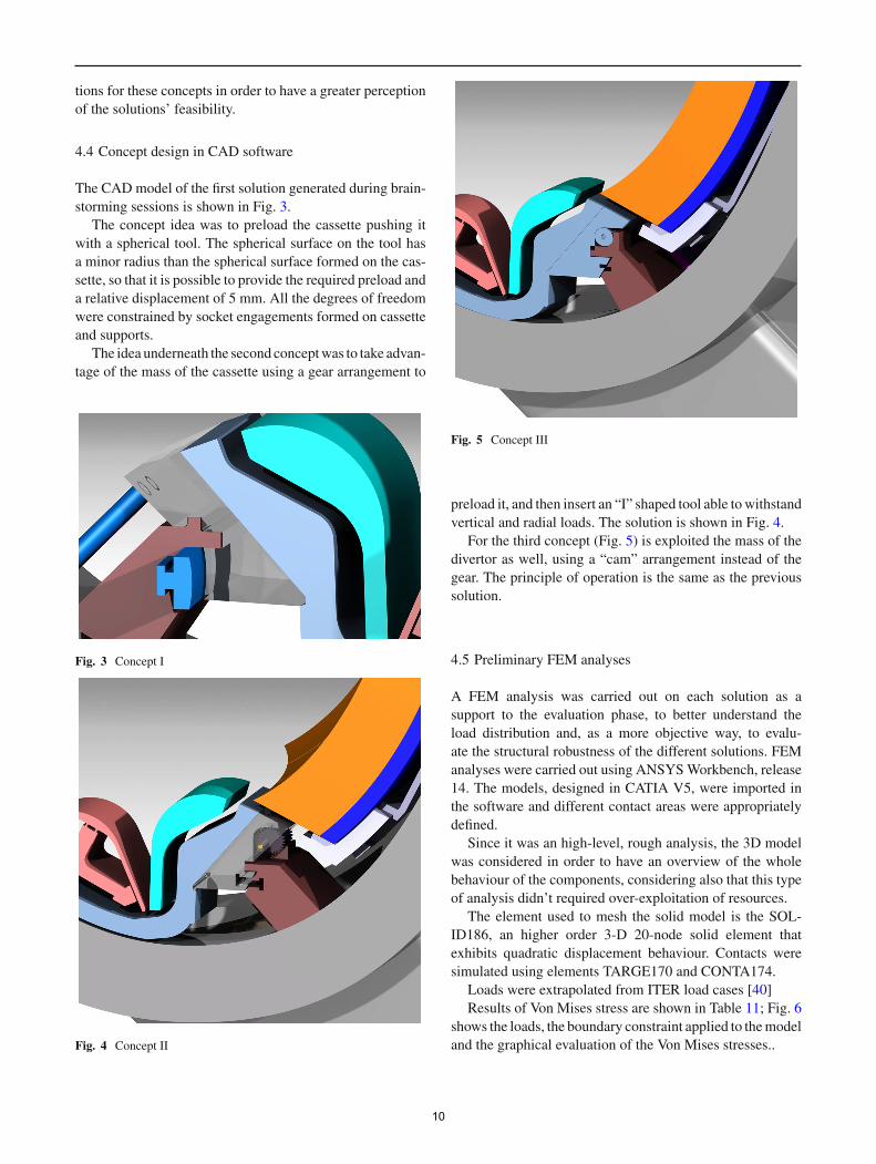
Fig. 5 Concept III
preload it, and then insert an “I” shaped tool able towithstandvertical and radial loads. The solution is shown in Fig. 4.
For the third concept (Fig. 5) is exploited the mass of thedivertor as well, using a “cam” arrangement instead of thegear. The principle of operation is the same as the previoussolution.
4.5 Preliminary FEM analyses
A FEM analysis was carried out on each solution as asupport to the evaluation phase, to better understand theload distribution and, as a more objective way, to evalu-ate the structural robustness of the different solutions. FEManalyses were carried out using ANSYSWorkbench, release14. The models, designed in CATIA V5, were imported inthe software and different contact areas were appropriatelydefined.
Since it was an high-level, rough analysis, the 3D modelwas considered in order to have an overview of the wholebehaviour of the components, considering also that this typeof analysis didn’t required over-exploitation of resources.
The element used to mesh the solid model is the SOL-ID186, an higher order 3-D 20-node solid element thatexhibits quadratic displacement behaviour. Contacts weresimulated using elements TARGE170 and CONTA174.
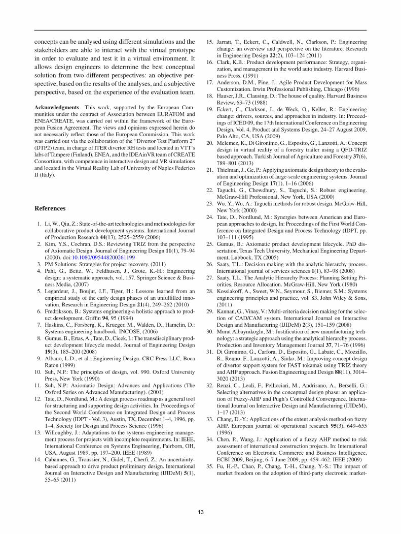
Loads were extrapolated from ITER load cases [40]Results of Von Mises stress are shown in Table 11; Fig. 6
shows the loads, the boundary constraint applied to themodeland the graphical evaluation of the Von Mises stresses..
10
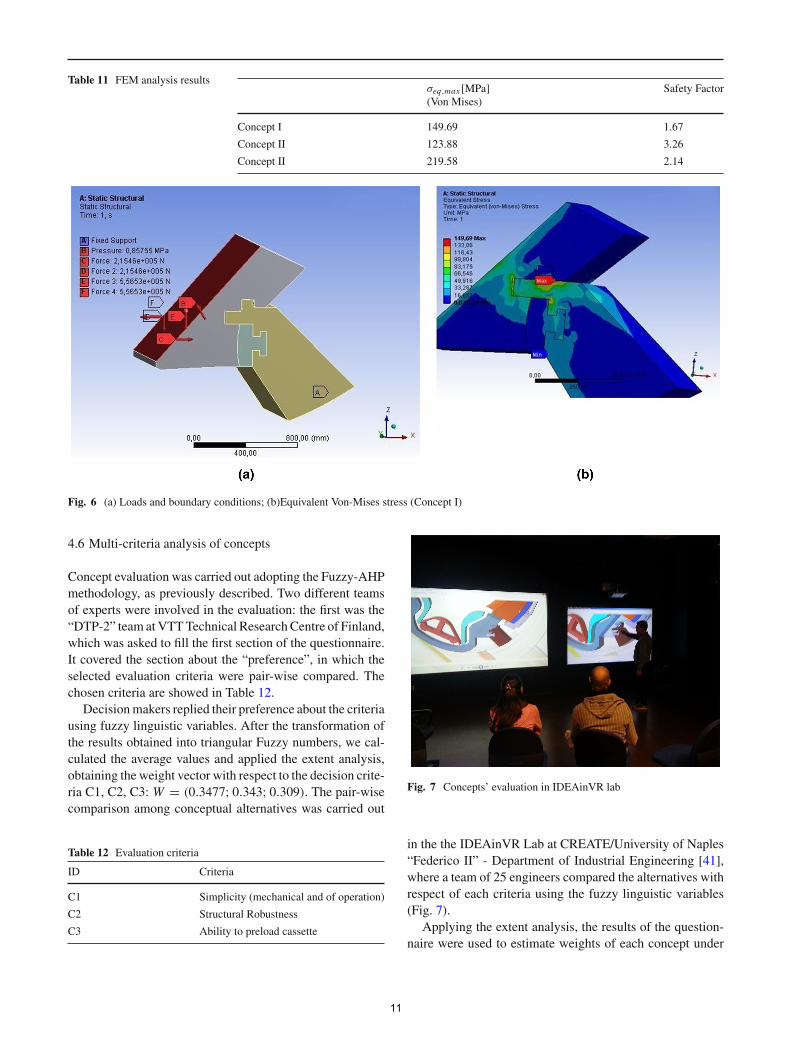
Table 11 FEM analysis resultsσeq,max [MPa](Von Mises)
Safety Factor
Concept I 149.69 1.67
Concept II 123.88 3.26
Concept II 219.58 2.14
Fig. 6 (a) Loads and boundary conditions; (b)Equivalent Von-Mises stress (Concept I)
4.6 Multi-criteria analysis of concepts
Concept evaluation was carried out adopting the Fuzzy-AHPmethodology, as previously described. Two different teamsof experts were involved in the evaluation: the first was the“DTP-2” team atVTTTechnical ResearchCentre of Finland,which was asked to fill the first section of the questionnaire.It covered the section about the “preference”, in which theselected evaluation criteria were pair-wise compared. Thechosen criteria are showed in Table 12.
Decisionmakers replied their preference about the criteriausing fuzzy linguistic variables. After the transformation ofthe results obtained into triangular Fuzzy numbers, we cal-culated the average values and applied the extent analysis,obtaining the weight vector with respect to the decision crite-ria C1, C2, C3: W = (0.3477; 0.343; 0.309). The pair-wisecomparison among conceptual alternatives was carried out
Table 12 Evaluation criteria
ID Criteria
C1 Simplicity (mechanical and of operation)
C2 Structural Robustness
C3 Ability to preload cassette
Fig. 7 Concepts’ evaluation in IDEAinVR lab
in the the IDEAinVR Lab at CREATE/University of Naples“Federico II” - Department of Industrial Engineering [41],where a team of 25 engineers compared the alternatives withrespect of each criteria using the fuzzy linguistic variables(Fig. 7).
Applying the extent analysis, the results of the question-naire were used to estimate weights of each concept under
11
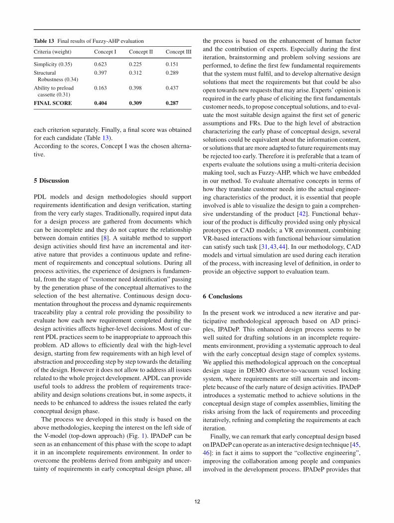
Table 13 Final results of Fuzzy-AHP evaluation
Criteria (weight) Concept I Concept II Concept III
Simplicity (0.35) 0.623 0.225 0.151
StructuralRobustness (0.34)
0.397 0.312 0.289
Ability to preloadcassette (0.31)
0.163 0.398 0.437
FINAL SCORE 0.404 0.309 0.287
the process is based on the enhancement of human factorand the contribution of experts. Especially during the firstiteration, brainstorming and problem solving sessions areperformed, to define the first few fundamental requirementsthat the system must fulfil, and to develop alternative designsolutions that meet the requirements but that could be alsoopen towards new requests thatmay arise. Experts’ opinion isrequired in the early phase of eliciting the first fundamentalscustomer needs, to propose conceptual solutions, and to eval-uate the most suitable design against the first set of genericassumptions and FRs. Due to the high level of abstractioncharacterizing the early phase of conceptual design, severalsolutions could be equivalent about the information content,or solutions that aremore adapted to future requirementsmaybe rejected too early. Therefore it is preferable that a team ofexperts evaluate the solutions using a multi-criteria decisionmaking tool, such as Fuzzy-AHP, which we have embeddedin our method. To evaluate alternative concepts in terms ofhow they translate customer needs into the actual engineer-ing characteristics of the product, it is essential that peopleinvolved is able to visualize the design to gain a comprehen-sive understanding of the product [42]. Functional behav-iour of the product is difficulty provided using only physicalprototypes or CAD models; a VR environment, combiningVR-based interactions with functional behaviour simulationcan satisfy such task [31,43,44]. In our methodology, CADmodels and virtual simulation are used during each iterationof the process, with increasing level of definition, in order toprovide an objective support to evaluation team.
6 Conclusions
In the present work we introduced a new iterative and par-ticipative methodological approach based on AD princi-ples, IPADeP. This enhanced design process seems to bewell suited for drafting solutions in an incomplete require-ments environment, providing a systematic approach to dealwith the early conceptual design stage of complex systems.We applied this methodological approach on the conceptualdesign stage in DEMO divertor-to-vacuum vessel lockingsystem, where requirements are still uncertain and incom-plete because of the early nature of design activities. IPADePintroduces a systematic method to achieve solutions in theconceptual design stage of complex assemblies, limiting therisks arising from the lack of requirements and proceedingiteratively, refining and completing the requirements at eachiteration.
Finally, we can remark that early conceptual design basedon IPADePcanoperate as an interactive design technique [45,46]: in fact it aims to support the “collective engineering”,improving the collaboration among people and companiesinvolved in the development process. IPADeP provides that
each criterion separately. Finally, a final score was obtained for each candidate (Table 13).According to the scores, Concept I was the chosen alterna-tive.
5 Discussion
PDL models and design methodologies should support requirements identification and design verification, starting from the very early stages. Traditionally, required input data for a design process are gathered from documents which can be incomplete and they do not capture the relationship between domain entities [8]. A suitable method to support design activities should first have an incremental and iter-ative nature that provides a continuous update and refine-ment of requirements and conceptual solutions. During all process activities, the experience of designers is fundamen-tal, from the stage of “customer need identification” passing by the generation phase of the conceptual alternatives to the selection of the best alternative. Continuous design docu-mentation throughout the process and dynamic requirements traceability play a central role providing the possibility to evaluate how each new requirement completed during the design activities affects higher-level decisions. Most of cur-rent PDL practices seem to be inappropriate to approach this problem. AD allows to efficiently deal with the high-level design, starting from few requirements with an high level of abstraction and proceeding step by step towards the detailing of the design. However it does not allow to address all issues related to the whole project development. APDL can provide useful tools to address the problem of requirements trace-ability and design solutions creations but, in some aspects, it needs to be enhanced to address the issues related the early conceptual design phase.
The process we developed in this study is based on the above methodologies, keeping the interest on the left side of the V-model (top-down approach) (Fig. 1). IPADeP can be seen as an enhancement of this phase with the scope to adapt it in an incomplete requirements environment. In order to overcome the problems derived from ambiguity and uncer-tainty of requirements in early conceptual design phase, all
12
concepts can be analysed using different simulations and thestakeholders are able to interact with the virtual prototypein order to evaluate and test it in a virtual environment. Itallows design engineers to determine the best conceptualsolution from two different perspectives: an objective per-spective, based on the results of the analyses, and a subjectiveperspective, based on the experience of the evaluation team.
Acknowledgments This work, supported by the European Com-munities under the contract of Association between EURATOM andENEA/CREATE, was carried out within the framework of the Euro-pean Fusion Agreement. The views and opinions expressed herein donot necessarily reflect those of the European Commission. This workwas carried out via the collaboration of the “Divertor Test Platform 2”(DTP2) team, in charge of ITER divertor RH tests and located in VTT’slabs of Tampere (Finland), ENEA, and the IDEAinVR teamofCREATEConsortium, with competence in interactive design and VR simulationsand located in the Virtual Reality Lab of University of Naples FedericoII (Italy).
References
1. Li,W.,Qiu, Z.: State-of-the-art technologies andmethodologies forcollaborative product development systems. International Journalof Production Research 44(13), 2525–2559 (2006)
2. Kim, Y.S., Cochran, D.S.: Reviewing TRIZ from the perspectiveof Axiomatic Design. Journal of Engineering Design 11(1), 79–94(2000). doi:10.1080/095448200261199
3. PM Solutions: Strategies for project recovery. (2011)4. Pahl, G., Beitz, W., Feldhusen, J., Grote, K.-H.: Engineering
design: a systematic approach, vol. 157. Springer Science & Busi-ness Media, (2007)
5. Legardeur, J., Boujut, J.F., Tiger, H.: Lessons learned from anempirical study of the early design phases of an unfulfilled inno-vation. Research in Engineering Design 21(4), 249–262 (2010)
6. Fredriksson, B.: Systems engineering-a holistic approach to prod-uct development. Griffin 94, 95 (1994)
7. Haskins, C., Forsberg, K., Krueger, M., Walden, D., Hamelin, D.:Systems engineering handbook. INCOSE, (2006)
8. Gumus,B., Ertas,A., Tate,D.,Cicek, I.: The transdisciplinary prod-uct development lifecycle model. Journal of Engineering Design19(3), 185–200 (2008)
9. Albano, L.D., et al.: Engineering Design. CRC Press LLC, BocaRaton (1999)
10. Suh, N.P.: The principles of design, vol. 990. Oxford UniversityPress, New York (1990)
11. Suh, N.P.: Axiomatic Design: Advances and Applications (TheOxford Series on Advanced Manufacturing). (2001)
12. Tate, D., Nordlund,M.: A design process roadmap as a general toolfor structuring and supporting design activities. In: Proceedings ofthe Second World Conference on Integrated Design and ProcessTechnology (IDPT - Vol. 3), Austin, TX, December 1–4, 1996, pp.1–4. Society for Design and Process Science (1996)
13. Willoughby, J.: Adaptations to the systems engineering manage-ment process for projects with incomplete requirements. In: IEEE,International Conference on Systems Engineering, Fairborn, OH,USA, August 1989, pp. 197–200. IEEE (1989)
14. Cabannes, G., Troussier, N., Gidel, T., Cherfi, Z.: An uncertainty-based approach to drive product preliminary design. InternationalJournal on Interactive Design and Manufacturing (IJIDeM) 5(1),55–65 (2011)
15. Jarratt, T., Eckert, C., Caldwell, N., Clarkson, P.: Engineeringchange: an overview and perspective on the literature. Researchin Engineering Design 22(2), 103–124 (2011)
16. Clark, K.B.: Product development performance: Strategy, organi-zation, and management in the world auto industry. Harvard Busi-ness Press, (1991)
17. Anderson, D.M., Pine, J.: Agile Product Development for MassCustomization. Irwin Professional Publishing, Chicago (1996)
18. Hauser, J.R., Clausing, D.: The house of quality. Harvard BusinessReview, 63–73 (1988)
19. Eckert, C., Clarkson, J., de Weck, O., Keller, R.: Engineeringchange: drivers, sources, and approaches in industry. In: Proceed-ings of ICED 09, the 17th International Conference on EngineeringDesign, Vol. 4, Product and Systems Design, 24–27 August 2009,Palo Alto, CA, USA (2009)
20. Melemez, K., Di Gironimo, G., Esposito, G., Lanzotti, A.: Conceptdesign in virtual reality of a forestry trailer using a QFD-TRIZbased approach. Turkish Journal of Agriculture and Forestry 37(6),789–801 (2013)
21. Thielman, J., Ge, P.: Applying axiomatic design theory to the evalu-ation and optimization of large-scale engineering systems. Journalof Engineering Design 17(1), 1–16 (2006)
22. Taguchi, G., Chowdhury, S., Taguchi, S.: Robust engineering.McGraw-Hill Professional, New York, USA (2000)
23. Wu, Y., Wu, A.: Taguchi methods for robust design. McGraw-Hill,New York (2000)
24. Tate, D., Nordlund, M.: Synergies between American and Euro-pean approaches to design. In: Proceedings of the First World Con-ference on Integrated Design and Process Technology (IDPT, pp.103–111 (1995)
25. Gumus, B.: Axiomatic product development lifecycle. PhD dis-sertation, Texas Tech University, Mechanical Engineering Depart-ment, Lubbock, TX (2005)
26. Saaty, T.L.: Decision making with the analytic hierarchy process.International journal of services sciences 1(1), 83–98 (2008)
27. Saaty, T.L.: The Analytic Hierarchy Process: Planning Setting Pri-orities, Resource Allocation. McGraw-Hill, New York (1980)
28. Kossiakoff, A., Sweet, W.N., Seymour, S., Biemer, S.M.: Systemsengineering principles and practice, vol. 83. John Wiley & Sons,(2011)
29. Kannan, G., Vinay, V.:Multi-criteria decisionmaking for the selec-tion of CAD/CAM system. International Journal on InteractiveDesign and Manufacturing (IJIDeM) 2(3), 151–159 (2008)
30. Murat Albayrakoglu, M.: Justification of new manufacturing tech-nology: a strategic approach using the analytical hierarchy process.Production and Inventory Management Journal 37, 71–76 (1996)
31. Di Gironimo, G., Carfora, D., Esposito, G., Labate, C., Mozzillo,R., Renno, F., Lanzotti, A., Siuko, M.: Improving concept designof divertor support system for FAST tokamak using TRIZ theoryand AHP approach. Fusion Engineering and Design 88(11), 3014–3020 (2013)
32. Renzi, C., Leali, F., Pellicciari, M., Andrisano, A., Berselli, G.:Selecting alternatives in the conceptual design phase: an applica-tion of Fuzzy-AHP and Pugh’s Controlled Convergence. Interna-tional Journal on Interactive Design and Manufacturing (IJIDeM),1–17 (2013)
33. Chang, D.-Y.: Applications of the extent analysis method on fuzzyAHP. European journal of operational research 95(3), 649–655(1996)
34. Chen, P., Wang, J.: Application of a fuzzy AHP method to riskassessment of international construction projects. In: InternationalConference on Electronic Commerce and Business Intelligence,ECBI 2009, Beijing, 6–7 June 2009, pp. 459–462. IEEE (2009)
35. Fu, H.-P., Chao, P., Chang, T.-H., Chang, Y.-S.: The impact ofmarket freedom on the adoption of third-party electronic market-
13
places: a fuzzy AHP analysis. Industrial Marketing Management37(6), 698–712 (2008)
36. Romanelli, F., Federici, L.H., Neu, R., Stork, D., Zohm, H.: Aroadmap to the realization of fusion energy. In: Proc. IEEE 25thSymp. Fusion Eng, pp. 1–4 (2013)
37. Maisonnier, D., Cook, I., Pierre, S., Lorenzo, B., Luigi, D.P.,Luciano, G., Prachai, N., Aldo, P.: DEMO and fusion power plantconceptual studies in Europe. Fusion Engineering and Design81(8), 1123–1130 (2006)
38. Lyytikäinen, V., Kinnunen, P., Koivumäki, J., Mattila, J., Siuko,M., Esque, S., Palmer, J.: Divertor cassette locking system remotehandling trials with WHMAN at DTP2. Fusion Engineering andDesign 88(9), 2181–2185 (2013)
39. Carfora, D., Di Gironimo, G., Järvenpää, J., Huhtala, K., Määttä,T., Siuko, M.: Preliminary concept design of the divertor remotehandling system for DEMO power plant. Fusion Engineering andDesign (2014)
40. Komarov,V., Heidl, H., Tivey, R., Palmer, J.: Design progress of theITER divertor cassette-to-vacuum vessel locking system. FusionEngineering and Design 82(15), 1866–1870 (2007)
41. Di Gironimo, G., Mozzillo, R., Tarallo, A.: From virtual reality toweb-basedmultimediamaintenancemanuals. International Journalon Interactive Design and Manufacturing (IJIDeM) 7(3), 183–190(2013)
42. Liu, S., Boyle, I.M.: Engineering design: perspectives, challenges,and recent advances. Journal of Engineering Design 20(1), 7–19(2009)
43. Park, H., Son, J.-S., Lee, K.-H.: Design evaluation of digital con-sumer products using virtual reality-based functional behavioursimulation. Journal of Engineering Design 19(4), 359–375 (2008)
44. Di Gironimo, G., Matrone, G., Tarallo, A., Trotta, M., Lanzotti, A.:A virtual reality approach for usability assessment: case study ona wheelchair-mounted robot manipulator. Engineering with Com-puters 29(3), 359–373 (2013)
45. Carvajal-Arango, R., Zuluaga-Holguín, D., Mejía-Gutiérrez, R.: Asystems-engineering approach for virtual/real analysis and valida-tion of an automated greenhouse irrigation system. InternationalJournal on Interactive Design and Manufacturing (IJIDeM), 1–13(2014)
46. Fischer, X., Coutellier, D.: Research in Interactive Design: Pro-ceedings of Virtual Concept 2005. Springer Science & BusinessMedia, (2006)
14