ANCHORING WINCHES MONITORING SYSTEM
7
ANCHORING WINCHES MONITORING SYSTEM Tomislav Tomiša and Damir Krovinović Faculty of Electrical Engineering and Computing, Unska 3, HR-10000 Zagreb, Croatia e-mail: [email protected] ABSTRACT: The anchoring system of the pentagonal semi-submersible drilling platform “ZAGREB 1” was designed for anchoring depth up to 250 m. The system consists of 5 pairs anchoring winches which serve 10 symmetrical wire rope anchor lines and anchors. Each pair of anchoring winches was controlled from the local control station on the platform column. In accordance to the feasibility study of the anchoring system in the new environmental condition - sea depth up to 470 m, the existing anchoring winches control system is upgraded (using PLC/PC based hardware), to ensure synchronized operations of anchoring winches from one central location on the platform - control room. Key words: drilling platform, anchoring system, monitoring system, touch-screen, SCADA 1 ANCHORING PROCEDURE The pentagonal semi- submersible drilling platform is anchored by 10 symmetrical wire rope anchor lines and anchors. There are two anchoring winches positioned on each column of the platform labeled as A, B, C, D and E. (the winches are numbered from 1 to 10 in clockwise direction starting from a starboard winch on the column C) as schematically shown on Fig. 1. Fig. 1. Anchoring line pretension scheme
Transcript of ANCHORING WINCHES MONITORING SYSTEM

ANCHORING WINCHES MONITORING SYSTEM
Tomislav Tomiša and Damir Krovinović
Faculty of Electrical Engineering and Computing, Unska 3, HR-10000 Zagreb, Croatiae-mail: [email protected]
ABSTRACT: The anchoring system of the pentagonal semi-submersible drilling platform “ZAGREB 1” was designed for anchoring depth up to 250 m. The system consists of 5 pairs anchoring winches which serve 10 symmetrical wire rope anchor lines and anchors. Each pair of anchoring winches was controlled from the local control station on the platform column. In accordance to the feasibility study of the anchoring system in the new environmental condition - sea depth up to 470 m, the existing anchoring winches control system is upgraded (using PLC/PC based hardware), to ensure synchronized operations of anchoring winches from one central location on the platform - control room.
Key words: drilling platform, anchoring system, monitoring system, touch-screen, SCADA
1 ANCHORING PROCEDURE
Fig. 1. Anchoring line pretension scheme

The pentagonal semi-
submersible drilling platform is anchored by 10 symmetrical wire rope anchor lines and anchors. There are two anchoring winches positioned on each column of the platform labeled as A, B, C, D and E. (the winches are numbered from 1 to 10 in clockwise direction starting from a starboard winch on the column C) as schematically shown on Fig. 1.
Since all of the anchoring lines must be tested before the platform starts to work, the pre-tensioning procedure should be performed for each line to ensure proper penetration of the anchor in the seabed. The test is usually performed successively on two diametrically opposite lines when the winch capacity is sufficient with respect to the required tension force. |In the case when the winch capacity is insufficient to produce required line tension force but all other components fulfil the safety requirements, the pre-tension test may be performed by synchronized work of several winches (HA) on the one side of the platform while the tested anchor line (HO) on the opposite side is blocked by the static brake. To avoid undesired displacement of the platform from the drilling position during such procedure, the simultaneous control of several winches should be enabled. Since the tension force and the platform displacement depend on the anchor depth and must be calculated for each anchoring position, the computer based central monitoring system is installed in the control room that enables monitoring all of anchoring system parameters and steering the winches from one place to satisfy the prescribed anchoring procedure.
2 MONITORING SYSTEM CONFIGURATION
The existing anchoring system enables steering with particular pair of winches only from the local control station suited near the winches on the top of the column as shown on Fig. 2. In order to perform the new defined pre-tension procedure, which requires simultaneous operation with three pairs of winches the existing measuring equipment is upgraded with appropriate sensors and transducers to ensure acquisition of following data for each winch:

winch barrel-brake status winch motor rotation direction winch motor load current anchor line payoff count anchoring line strain.
Since the local control stations are placed around the platform, to collect the input signals from field equipment, the monitoring system is realized as the network of distributed PLC subsystems.
The local PLC subsystem transfers data (measurements and status signals) to the master PLC unit in control room using high-speed local area network.
The master PLC unit communicates with the PC workstation which is used as man machine
interface (MMI) for the operator to exchange data for visualization purposes.
The MMI is realized using 12” flat color monitor with touch sensitive screen, substituting standard input devices as keyboard and mouse.
The MMI is mounted above control desk in the control room as shown on Fig. 3.
The laser printer for hard copy purposes is placed inside the control desk.
The complete anchoring winches monitoring system configuration is shown on Fig. 4.
Fig. 2. Winch local control station
Fig. 3. Touch-screen MMI

Fig. 4. Monitoring system configuration
3 INTERACTIVE SCADA SOFTWARE
Since the PC based workstation with a touch-screen color monitor is used as the MMI to the monitoring system, the new SCADA software is developed for the data visualization and storage using Windows95/NT system platform, which ensures:
on-line monitoring of each anchor line tension on-line monitoring of each anchor line payoff and bi-directional speed on-line monitoring of each winch motor current permanent logging of all relevant data for trending purpose alarming on excessive line tension, loss of line tension, anchor winch over-speed, anchor winch
motor over-current low/high alarm setting for each measured value replay/review of all saved data on the screen (event/alarm list, diagrams etc.) reporting and hardcopy of all reports.
The data visualization is realized as the set of hierarchically organized pop-up pages using a high-resolution color graphics, while the operator’s commands are accepted by simple finger touch actions. During a normal drilling operation the main page is presented on the screen containing the basic data for each winch as shown on Fig. 5.

Fig. 5. Touch-screen main page layout
The central polar diagram scaled in real units is used for the on-line presentation of magnitude and direction of the resultant anchoring force vector. The excessive magnitude may be result of an additional force to the floating platform caused by waves and/or see-current as well by loss of anchoring line tension caused by moving the anchor, breaking the rope or the winch brake malfunction. In such case an alarm is automatically generated if resultant magnitude exceeds the pre-set value.
In the bottom of the main page there are SERVICE command button which activates system service functions, and GRAPH command button which activates graphical presentation of the resultant strain vector trend.
When particular data for the specific winch are of interest, the appropriate winch select button is used to pop-up the winch page on the screen. Each winch page contains all relevant data for corresponded winch pair as shown on Fig. 6.
Such presentation is very helpful during anchoring procedure as well during normal operation. The line payoff counter scaled in meters is used for correct anchor positioning, while the strain and speed indicator as well as motor current meters help to prevent an overload of the winch.
Since all measured data for each winch are permanently stored on the disk, the graphical presentation of historical data is available on the operator request by touching the corresponded TREND button in the bottom of the screen.
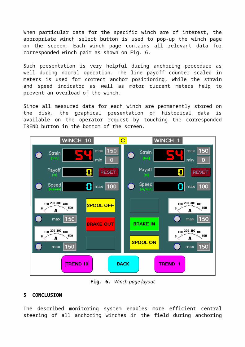
Fig. 6. Winch page layout
5 CONCLUSION
The described monitoring system enables more efficient central steering of all anchoring winches in the field during anchoring and drilling procedures. The on-line data acquisition and graphical presentation ensures user friendly operator’s approach. This system will be used as the base to build up the platform stabilization control system, which should integrate the navigation and meteorology subsystems to prevent excessive platform displacement in rough environmental conditions.
6 REFERENCES
[1] Čorić V., Feasibility Study Of Anchor System On The Submersible Oil Rig ZAGREB 1, report, CTT-Centre of Technology Transfer, FSB Zagreb, Croatia, 1998
[2] Tomiša T., Krovinović D., ZAGREB-1 Anchoring winches monitoring system, users manual, Trecom, Italy, 1998
SUSTAV NADZORA SIDRENIH VITLA – Sustav sidrenja pentagonalne platforme ZAGREB-1 projektiran je za dubine sidrenja do 250 m. Sustav čini 5 pari sidrenih vitla koji opslužuju 10 simetrično raspodijeljenih sidrenih linija sa sidrima. Izvorno upravljanje predviđeno je lokalno iz kontrolne kabine uz svaki par vitla. U skladu sa studijom mogućnosti sidrenja platforme na većim dubinama - do 470 m, postojeći sustav upravljanja vitlima je opremljen distribuiranom mrežom PLC jedinica i centralnim PC računalom što omogućuje provođenje posebne procedure sinkroniziranog upravljanja vitlima s jednog mjesta – iz kontrolne prostorije na platformi.
Ključne riječi: bušeća platforma, sustav sidrenja, nadzorni sustav, interaktivni zaslon, SCADA