
Anchor Fastening Technology Manual - Hilti · PDF fileAnchor Fastening Technology Manual -HY...
15
Hilti HIT-HY 170 mortar with rebar (as anchor) 1 November 3, 2016 Anchor Fastening Technology Manual HIT-HY 170 mortar with rebar (as anchor) Version 2016-10
-
Upload
nguyenkhanh -
Category
Documents
-
view
246 -
download
5
Transcript of Anchor Fastening Technology Manual - Hilti · PDF fileAnchor Fastening Technology Manual -HY...
Hilti HIT-HY 170 mortar with rebar (as anchor)
1 November 3, 2016
Anchor Fastening
Technology Manual
HIT-HY 170 mortar with rebar (as anchor)
Version 2016-10

Hilti HIT-HY 170 mortar with rebar (as anchor)
November 3, 2016 2
Hilti HIT-HY 170 mortar with rebar (as anchor)
Injection mortar system Benefits
Hilti HIT-HY 170 500 ml foil pack (also available as 330 ml foil pack)
- suitable for concrete C12/15 to C50/60
- suitable for dry and water saturated concrete
- high loading capacity and fast cure
- for rebar diameters up to 25 mm
- in service temperature range up to 80°C short term/50°C long term
- manual cleaning for drill hole
sizes 18 mm and embedment
depth hef 10d
- Suitable for embedment depth up to 300 mm depending on the rebar diameter
Static mixer
Rebar B500 B
Base material Load conditions
Concrete (non-cracked)
Static/quasi-static
Installation conditions Other information
Hammer drilled holes
Dry concrete
Water saturated concrete
CE conformity

Hilti HIT-HY 170 mortar with rebar (as anchor)
3 November 3, 2016
Basic loading data (for a single anchor)
All data in this section applies to For details see Simplified design method - Correct setting (See setting instruction) - No edge distance and spacing influence - Steel failure - Base material thickness, as specified in the table - One typical embedment depth, as specified in the table - One anchor material, as specified in the tables - Concrete C 20/25, fck,cube = 25 N/mm²
- Temperate range I (min. base material temperature -40°C, max. long term/short term base material temperature: +24°C/40°C)
- Installation temperature range -5°C to +40°C
Embedment depth and base material thickness for the basic loading data
Anchor size Ø8 Ø10 Ø12 Ø14 Ø16 Ø18 Ø20 Ø22 Ø24 Ø25
Typical embedment depth [mm] 80 90 110 125 145 155 170 185 200 210
Base material thickness [mm] 110 120 140 161 185 199 220 237 256 274
a) The allowed range of embedment depth is shown in the setting details. The corresponding load values can be calculated according to the simplified design method.
For hammer drilled holes: Mean ultimate resistance Anchor size Ø8 Ø10 Ø12 Ø14 Ø16 Ø18 Ø20 Ø22 Ø24 Ø25
Tensile NRu,m BSt 500 S [kN] 26,7 37,5 55,1 78,2 96,8 116,4 141,8 168,7 189,6 204,0
Shear VRu,m BSt 500 S [kN] 14,7 23,1 32,6 44,1 57,8 73,5 90,3 109,2 130,2 141,8
Characteristic resistance Anchor size Ø8 Ø10 Ø12 Ø14 Ø16 Ø18 Ø20 Ø22 Ø24 Ø25
Tensile NRk BSt 500 S [kN] 20,1 28,3 41,5 58,9 72,9 87,7 106,8 127,1 142,8 153,7
Shear VRk BSt 500 S [kN] 14,0 22,0 31,0 42,0 55,0 70,0 86,0 104,0 124,0 135,0
Design resistance
Anchor size Ø8 Ø10 Ø12 Ø14 Ø16 Ø18 Ø20 Ø22 Ø24 Ø25
Tensile NRd BSt 500 S [kN] 13,4 18,8 27,6 39,3 48,6 58,4 71,2 84,7 95,2 102,5
Shear VRd BSt 500 S [kN] 11,2 17,6 24,8 33,6 44,0 56,0 68,8 83,2 99,2 108,0
Recommended loads Anchor size Ø8 Ø10 Ø12 Ø14 Ø16 Ø18 Ø20 Ø22 Ø24 Ø25
Tensile Nrec BSt 500 S [kN] 9,6 13,5 19,7 28,0 34,7 41,7 50,9 60,5 68,0 73,2
Shear Vrec BSt 500 S [kN] 8,0 12,6 17,7 24,0 31,4 40,0 49,1 59,4 70,9 77,1
a) With overall partial safety factor for action = 1,4. The partial safety factors for action depend on the type of loading and shall be taken from national regulations.

Hilti HIT-HY 170 mortar with rebar (as anchor)
November 3, 2016 4
Service temperature range Hilti HIT-HY 170 injection mortar may be applied in the temperature ranges given below. An elevated base material temperature may lead to a reduction of the design bond resistance.
Temperature range Base material
temperature
Maximum long term
base material
temperature
Maximum short term
base material
temperature
Temperature range I -40 °C to +40 °C +24 °C +40 °C
Temperature range II -40 °C to +80 °C +50 °C +80 °C
Max short term base material temperature Short-term elevated base material temperatures are those that occur over brief intervals, e.g. as a result of diurnal cycling.
Max long term base material temperature Long-term elevated base material temperatures are roughly constant over significant periods of time.
Materials
Anchor size Ø8 Ø10 Ø12 Ø14 Ø16 Ø18 Ø20 Ø22 Ø24 Ø25
Nominal tensile strength fuk
BSt 500 S [N/mm²] 550 550 550 550 550 550 550 550 550 550
Yield strength fyk
BSt 500 S [N/mm²] 500 500 500 500 500 500 500 500 500 500
Stressed cross-section As
BSt 500 S [mm²] 50,3 78,5 113,1 153,9 201,1 254,0 314,2 380 452 490,9
Moment of resistance W
BSt 500 S [mm³] 50,3 98,2 169,6 269,4 402,1 572,6 785,4 1045,3 1357,2 1534
Material quality
Designation Material
Rebar EN 1992-1-1 Bars and de-coiled rods class B or C with fyk and k according to NDP or NCL of EN 1992-1-1 fuk = ftk = k · fyk
Setting
Installation equipment
Anchor size 8-16 18-25
Rotary hammer TE 2 (-A) – TE 30 (-A) TE 40 – TE 70
Other tools
Blow out hand pump hef ≤ 10.d
Compressed air gun
Set of cleaning brushes, dispenser, piston plug
Hilti HIT-HY 170 mortar with rebar (as anchor)
5 November 3, 2016
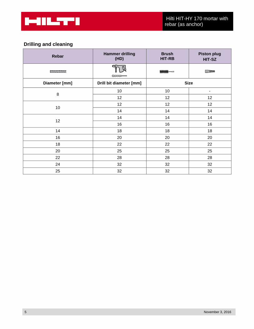
Drilling and cleaning
Rebar Hammer drilling
(HD) Brush HIT-RB
Piston plug
HIT-SZ
Diameter [mm] Drill bit diameter [mm] Size
8 10 10 -
12 12 12
1012 12 12
14 14 14
1214 14 14
16 16 16
14 18 18 18
16 20 20 20
18 22 22 22
20 25 25 25
22 28 28 28
24 32 32 32
25 32 32 32
Hilti HIT-HY 170 mortar with rebar (as anchor)
November 3, 2016 6
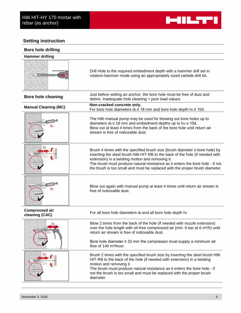
Setting instruction
Bore hole drilling
Hammer drilling
Drill Hole to the required embedment depth with a hammer drill set in rotation-hammer mode using an appropriately sized carbide drill bit.
Bore hole cleaning Just before setting an anchor, the bore hole must be free of dust and debris. Inadequate hole cleaning = poor load values.
Manual Cleaning (MC) Non-cracked concrete only. For bore hole diameters d0 ≤ 18 mm and bore hole depth h0 ≤ 10d.
The Hilti manual pump may be used for blowing out bore holes up to diameters d0 ≤ 18 mm and embedment depths up to hef ≤ 10d. Blow out at least 4 times from the back of the bore hole until return air stream is free of noticeable dust
Brush 4 times with the specified brush size (brush diameter ≥ bore hole) by inserting the steel brush Hilti HIT-RB to the back of the hole (if needed with extension) in a twisting motion and removing it. The brush must produce natural resistance as it enters the bore hole - if not the brush is too small and must be replaced with the proper brush diameter.
Blow out again with manual pump at least 4 times until return air stream is free of noticeable dust.
Compressed air cleaning (CAC)
For all bore hole diameters d0 and all bore hole depth h0
Blow 2 times from the back of the hole (if needed with nozzle extension) over the hole length with oil-free compressed air (min. 6 bar at 6 m³/h) until return air stream is free of noticeable dust. Bore hole diameter ≥ 32 mm the compressor must supply a minimum air flow of 140 m³/hour.
Brush 2 times with the specified brush size by inserting the steel brush Hilti HIT-RB to the back of the hole (if needed with extension) in a twisting motion and removing it. The brush must produce natural resistance as it enters the bore hole - if not the brush is too small and must be replaced with the proper brush diameter.

Hilti HIT-HY 170 mortar with rebar (as anchor)
7 November 3, 2016
Blow again with compressed air 2 times until return air stream is free of noticeable dust.
Injection preparation
Tightly attach new Hilti mixing nozzle HIT-RE-M to foil pack manifold (snug fit). Do not modify the mixing nozzle. Observe the instruction for use of the dispenser and mortar. Check foil pack holder for proper function. Do not use damaged foil packs / holders. Insert foil pack into foil pack holder and put holder into HIT-dispenser.
The foil pack opens automatically as dispensing is initiated. Discard initial adhesive. Depending on the size of the foil pack an initial amount of adhesive has to be discarded. Discard quantities are: 2 strokes for 330 ml foil pack, 3 strokes for 500 ml foil pack
Inject adhesive From the back of the drill hole without forming air voids
Inject the adhesive starting at the back of the hole, slowly withdrawing the mixer with each trigger pull. Fill holes approximately 2/3 full. It is required that the annular gap between the anchor and the concrete is completely filled with adhesive along the embedment length.
After injection is completed, depressurize the dispenser by pressing the release trigger. This will prevent further adhesive discharge from the mixer.
Overhead installation and/or installation with embedment depth hef > 250mm. For overhead installation the injection is only possible with the aid of extensions and piston plugs. Assemble HIT-RE-M mixer, extension(s) and appropriately sized piston plug HIT-SZ. Insert piston plug to back of the hole and inject adhesive. During injection the piston plug will be naturally extruded out of the bore hole by the adhesive pressure.
Hilti HIT-HY 170 mortar with rebar (as anchor)
November 3, 2016 8
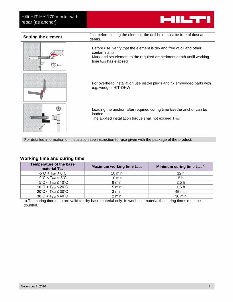
Setting the element Just before setting the element, the drill hole must be free of dust and debris.
Before use, verify that the element is dry and free of oil and other contaminants. Mark and set element to the required embedment depth untill working time twork has elapsed.
For overhead installation use piston plugs and fix embedded parts with e.g. wedges HIT-OHW.
Loading the anchor: after required curing time tcure the anchor can be loaded. The applied installation torque shall not exceed Tmax.
For detailed information on installation see instruction for use given with the package of the product.
Working time and curing time
Temperature of the base material TBM
Maximum working time twork Minimum curing time tcure a)
-5˚C ≤ TBM ≤ 0˚C 10 min 12 h
0˚C < TBM ≤ 5˚C 10 min 5 h
5˚C < TBM ≤ 10˚C 8 min 2,5 h
10˚C < TBM ≤ 20˚C 5 min 1,5 h
20˚C < TBM ≤ 30˚C 3 min 45 min
30˚C < TBM ≤ 40˚C 2 min 30 min
a) The curing time data are valid for dry base material only. In wet base material the curing times must be doubled.
Hilti HIT-HY 170 mortar with rebar (as anchor)
9 November 3, 2016
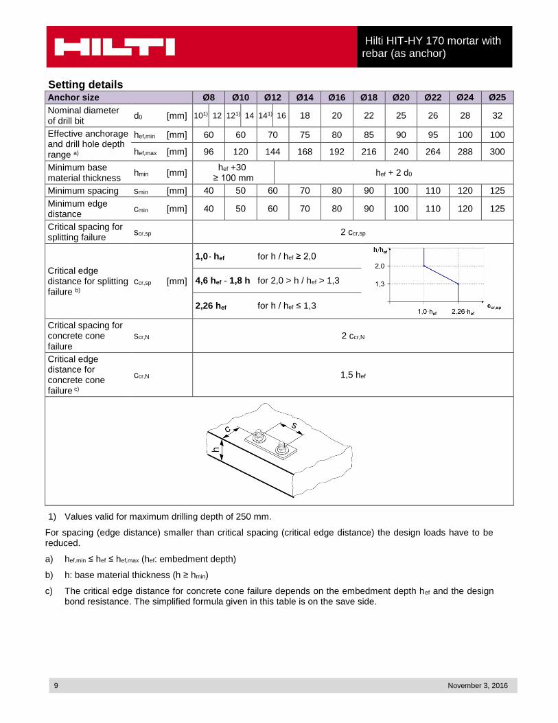
Setting details Anchor size Ø8 Ø10 Ø12 Ø14 Ø16 Ø18 Ø20 Ø22 Ø24 Ø25
Nominal diameter of drill bit
d0 [mm] 101) 12 121) 14 141) 16 18 20 22 25 26 28 32
Effective anchorage and drill hole depth range a)
hef,min [mm] 60 60 70 75 80 85 90 95 100 100
hef,max [mm] 96 120 144 168 192 216 240 264 288 300
Minimum base material thickness
hmin [mm] hef +30
≥ 100 mm hef + 2 d0
Minimum spacing smin [mm] 40 50 60 70 80 90 100 110 120 125
Minimum edge distance
cmin [mm] 40 50 60 70 80 90 100 110 120 125
Critical spacing for splitting failure
scr,sp 2 ccr,sp
Critical edge distance for splitting failure b)
ccr,sp [mm]
1,0 hef for h / hef ≥ 2,0
4,6 hef - 1,8 h for 2,0 > h / hef > 1,3
2,26 hef for h / hef ≤ 1,3
Critical spacing for concrete cone failure
scr,N 2 ccr,N
Critical edge distance for concrete cone failure c)
ccr,N 1,5 hef
1) Values valid for maximum drilling depth of 250 mm.
For spacing (edge distance) smaller than critical spacing (critical edge distance) the design loads have to be reduced.
a) hef,min ≤ hef ≤ hef,max (hef: embedment depth)
b) h: base material thickness (h ≥ hmin)
c) The critical edge distance for concrete cone failure depends on the embedment depth hef and the design bond resistance. The simplified formula given in this table is on the save side.

Hilti HIT-HY 170 mortar with rebar (as anchor)
November 3, 2016 10
Simplified design method
Simplified version of the design method according ETAG 001, TR 029. Influence of concrete strength Influence of edge distance Influence of spacing Valid for a group of two anchors. (The method may also be applied for anchor groups with more than two
anchors or more than one edge distance. The influencing factors must then be considered for each edge distance and spacing. The calculated design loads are then on the save side: They will be lower than the exact values according ETAG 001, TR 029. To avoid this, it is recommended to use the anchor design software PROFIS anchor)
The design method is based on the following simplification: No different loads are acting on individual anchors (no eccentricity)
Values are valid for one anchor.
For more complex fastening applications please use the anchor design software PROFIS Anchor.
Tension loading
The design tensile resistance is the lower value of
- Steel resistance: NRd,s
- Combined pull-out and concrete cone resistance:
NRd,p = N0Rd,p fB,p f1,N f2,N f3,N fh,p fre,N
- Concrete cone resistance: NRd,c = N0Rd,c fB f1,N f2,N f3,N fh,N fre,N
- Concrete splitting resistance (only non-cracked concrete):
NRd,sp = N0Rd,c fB f1,sp f2,sp f3,sp fh,N fre,N
Basic design tensile resistance
Design steel resistance NRd,s Anchor size Ø8 Ø10 Ø12 Ø14 Ø16 Ø18 Ø20 Ø22 Ø24 Ø25
NRd,s BSt 500 S [kN] 20,0 30,7 44,3 60,7 79,3 100,0 123,6 149,3 177,9 192,9
Design combined pull-out and concrete cone resistance
NRd,p = N0Rd,p fB,p f1,N f2,N f3,N fh,p fre,N
Anchor size Ø8 Ø10 Ø12 Ø14 Ø16 Ø18 Ø20 Ø22 Ø24 Ø25
Embedment depth hef [mm] 80 90 110 125 145 155 170 185 200 210
N0Rd,p
Temperature range I [kN] 13,4 18,8 27,6 39,3 48,6 58,4 71,2 85,2 100,5 110,0
Temperature range II [kN] 9,4 13,2 19,4 25,7 34,0 40,9 49,8 59,7 70,4 77,0
Hilti HIT-HY 170 mortar with rebar (as anchor)
11 November 3, 2016
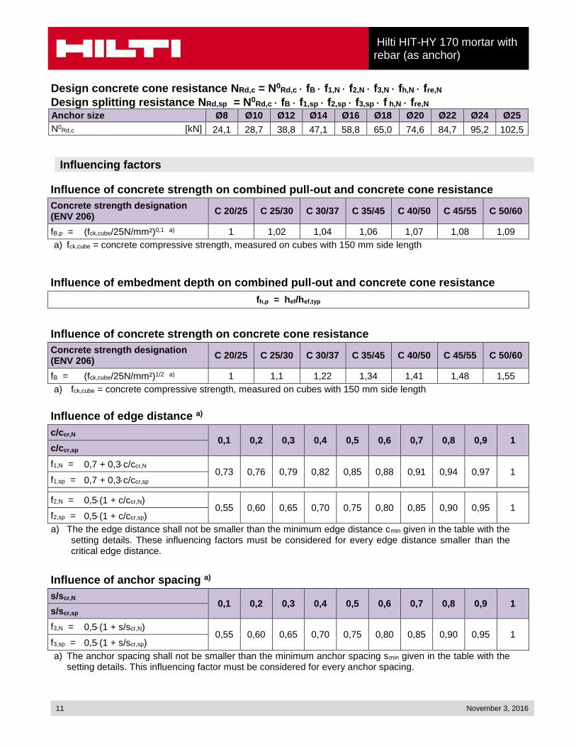
Design concrete cone resistance NRd,c = N0Rd,c fB f1,N f2,N f3,N fh,N fre,N
Design splitting resistance NRd,sp = N0Rd,c fB f1,sp f2,sp f3,sp f h,N fre,N
Anchor size Ø8 Ø10 Ø12 Ø14 Ø16 Ø18 Ø20 Ø22 Ø24 Ø25
N0Rd,c [kN] 24,1 28,7 38,8 47,1 58,8 65,0 74,6 84,7 95,2 102,5
Influencing factors
Influence of concrete strength on combined pull-out and concrete cone resistance
Concrete strength designation (ENV 206)
C 20/25 C 25/30 C 30/37 C 35/45 C 40/50 C 45/55 C 50/60
fB,p = (fck,cube/25N/mm²)0,1 a) 1 1,02 1,04 1,06 1,07 1,08 1,09
a) fck,cube = concrete compressive strength, measured on cubes with 150 mm side length
Influence of embedment depth on combined pull-out and concrete cone resistance
fh,p = hef/hef,typ
Influence of concrete strength on concrete cone resistance
Concrete strength designation (ENV 206)
C 20/25 C 25/30 C 30/37 C 35/45 C 40/50 C 45/55 C 50/60
fB = (fck,cube/25N/mm²)1/2 a) 1 1,1 1,22 1,34 1,41 1,48 1,55
a) fck,cube = concrete compressive strength, measured on cubes with 150 mm side length
Influence of edge distance a)
c/ccr,N 0,1 0,2 0,3 0,4 0,5 0,6 0,7 0,8 0,9 1
c/ccr,sp
f1,N = 0,7 + 0,3c/ccr,N 0,73 0,76 0,79 0,82 0,85 0,88 0,91 0,94 0,97 1
f1,sp = 0,7 + 0,3c/ccr,sp
f2,N = 0,5(1 + c/ccr,N) 0,55 0,60 0,65 0,70 0,75 0,80 0,85 0,90 0,95 1
f2,sp = 0,5(1 + c/ccr,sp)
a) The the edge distance shall not be smaller than the minimum edge distance cmin given in the table with the setting details. These influencing factors must be considered for every edge distance smaller than the critical edge distance.
Influence of anchor spacing a)
s/scr,N 0,1 0,2 0,3 0,4 0,5 0,6 0,7 0,8 0,9 1
s/scr,sp
f3,N = 0,5(1 + s/scr,N) 0,55 0,60 0,65 0,70 0,75 0,80 0,85 0,90 0,95 1
f3,sp = 0,5(1 + s/scr,sp)
a) The anchor spacing shall not be smaller than the minimum anchor spacing smin given in the table with the setting details. This influencing factor must be considered for every anchor spacing.
Hilti HIT-HY 170 mortar with rebar (as anchor)
November 3, 2016 12
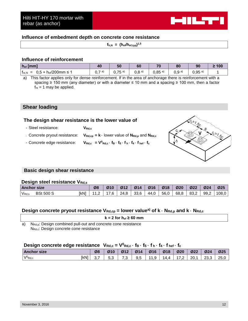
Influence of embedment depth on concrete cone resistance
fh,N = (hef/hef,typ)1,5
Influence of reinforcement
hef [mm] 40 50 60 70 80 90 ≥ 100
fre,N = 0,5 + hef/200mm ≤ 1 0,7 a) 0,75 a) 0,8 a) 0,85 a) 0,9 a) 0,95 a) 1
a) This factor applies only for dense reinforcement. If in the area of anchorage there is reinforcement with a spacing ≥ 150 mm (any diameter) or with a diameter ≤ 10 mm and a spacing ≥ 100 mm, then a factor fre = 1 may be applied.
Shear loading
The design shear resistance is the lower value of
- Steel resistance: VRd,s
- Concrete pryout resistance: VRd,cp = k lower value of NRd,p and NRd,c
- Concrete edge resistance: VRd,c = V0Rd,c fB fß f h f4 f hef fc
Basic design shear resistance
Design steel resistance VRd,s
Anchor size Ø8 Ø10 Ø12 Ø14 Ø16 Ø18 Ø20 Ø22 Ø24 Ø25
VRd,s BSt 500 S [kN] 11,2 17,6 24,8 33,6 44,0 56,0 68,8 83,2 99,2 108,0
Design concrete pryout resistance VRd,cp = lower valuea) of k NRd,p and k NRd,c
k = 2 for hef ≥ 60 mm
a) NRd,p: Design combined pull-out and concrete cone resistance NRd,c: Design concrete cone resistance
Design concrete edge resistance VRd,c = V0Rd,c fB fß f h f4 f hef fc
Anchor size Ø8 Ø10 Ø12 Ø14 Ø16 Ø18 Ø20 Ø22 Ø24 Ø25
V0Rd,c [kN] 3,7 5,3 7,3 9,5 11,9 14,4 17,2 20,1 23,3 25,0
Hilti HIT-HY 170 mortar with rebar (as anchor)
13 November 3, 2016
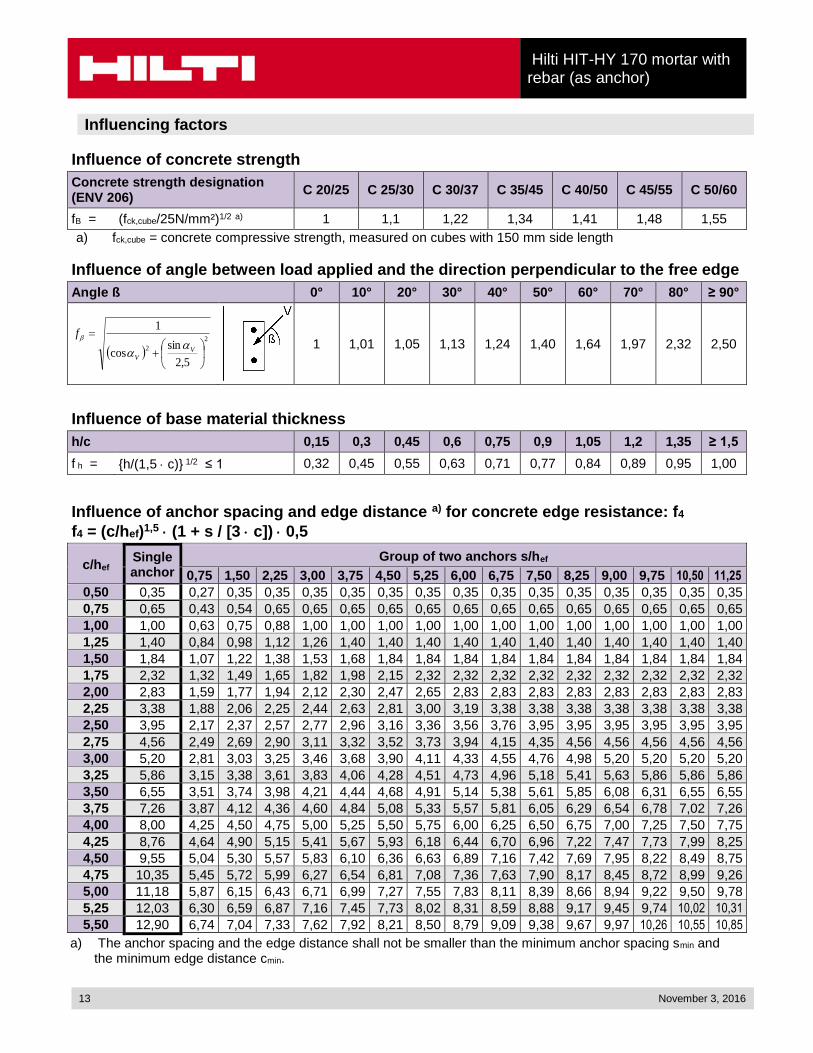
Influencing factors
Influence of concrete strength
Concrete strength designation (ENV 206)
C 20/25 C 25/30 C 30/37 C 35/45 C 40/50 C 45/55 C 50/60
fB = (fck,cube/25N/mm²)1/2 a) 1 1,1 1,22 1,34 1,41 1,48 1,55
a) fck,cube = concrete compressive strength, measured on cubes with 150 mm side length
Influence of angle between load applied and the direction perpendicular to the free edge
Angle ß 0° 10° 20° 30° 40° 50° 60° 70° 80° ≥ 90°
2
2
5,2
sincos
1
VV
f
1 1,01 1,05 1,13 1,24 1,40 1,64 1,97 2,32 2,50
Influence of base material thickness
h/c 0,15 0,3 0,45 0,6 0,75 0,9 1,05 1,2 1,35 ≥ 1,5
f h = {h/(1,5 c)} 1/2 ≤ 1 0,32 0,45 0,55 0,63 0,71 0,77 0,84 0,89 0,95 1,00
Influence of anchor spacing and edge distance a) for concrete edge resistance: f4
f4 = (c/hef)1,5 (1 + s / [3 c]) 0,5
c/hef Single anchor
Group of two anchors s/hef
0,75 1,50 2,25 3,00 3,75 4,50 5,25 6,00 6,75 7,50 8,25 9,00 9,75 10,50 11,25
0,50 0,35 0,27 0,35 0,35 0,35 0,35 0,35 0,35 0,35 0,35 0,35 0,35 0,35 0,35 0,35 0,35
0,75 0,65 0,43 0,54 0,65 0,65 0,65 0,65 0,65 0,65 0,65 0,65 0,65 0,65 0,65 0,65 0,65
1,00 1,00 0,63 0,75 0,88 1,00 1,00 1,00 1,00 1,00 1,00 1,00 1,00 1,00 1,00 1,00 1,00
1,25 1,40 0,84 0,98 1,12 1,26 1,40 1,40 1,40 1,40 1,40 1,40 1,40 1,40 1,40 1,40 1,40
1,50 1,84 1,07 1,22 1,38 1,53 1,68 1,84 1,84 1,84 1,84 1,84 1,84 1,84 1,84 1,84 1,84
1,75 2,32 1,32 1,49 1,65 1,82 1,98 2,15 2,32 2,32 2,32 2,32 2,32 2,32 2,32 2,32 2,32
2,00 2,83 1,59 1,77 1,94 2,12 2,30 2,47 2,65 2,83 2,83 2,83 2,83 2,83 2,83 2,83 2,83
2,25 3,38 1,88 2,06 2,25 2,44 2,63 2,81 3,00 3,19 3,38 3,38 3,38 3,38 3,38 3,38 3,38
2,50 3,95 2,17 2,37 2,57 2,77 2,96 3,16 3,36 3,56 3,76 3,95 3,95 3,95 3,95 3,95 3,95
2,75 4,56 2,49 2,69 2,90 3,11 3,32 3,52 3,73 3,94 4,15 4,35 4,56 4,56 4,56 4,56 4,56
3,00 5,20 2,81 3,03 3,25 3,46 3,68 3,90 4,11 4,33 4,55 4,76 4,98 5,20 5,20 5,20 5,20
3,25 5,86 3,15 3,38 3,61 3,83 4,06 4,28 4,51 4,73 4,96 5,18 5,41 5,63 5,86 5,86 5,86
3,50 6,55 3,51 3,74 3,98 4,21 4,44 4,68 4,91 5,14 5,38 5,61 5,85 6,08 6,31 6,55 6,55
3,75 7,26 3,87 4,12 4,36 4,60 4,84 5,08 5,33 5,57 5,81 6,05 6,29 6,54 6,78 7,02 7,26
4,00 8,00 4,25 4,50 4,75 5,00 5,25 5,50 5,75 6,00 6,25 6,50 6,75 7,00 7,25 7,50 7,75
4,25 8,76 4,64 4,90 5,15 5,41 5,67 5,93 6,18 6,44 6,70 6,96 7,22 7,47 7,73 7,99 8,25
4,50 9,55 5,04 5,30 5,57 5,83 6,10 6,36 6,63 6,89 7,16 7,42 7,69 7,95 8,22 8,49 8,75
4,75 10,35 5,45 5,72 5,99 6,27 6,54 6,81 7,08 7,36 7,63 7,90 8,17 8,45 8,72 8,99 9,26
5,00 11,18 5,87 6,15 6,43 6,71 6,99 7,27 7,55 7,83 8,11 8,39 8,66 8,94 9,22 9,50 9,78
5,25 12,03 6,30 6,59 6,87 7,16 7,45 7,73 8,02 8,31 8,59 8,88 9,17 9,45 9,74 10,02 10,31
5,50 12,90 6,74 7,04 7,33 7,62 7,92 8,21 8,50 8,79 9,09 9,38 9,67 9,97 10,26 10,55 10,85
a) The anchor spacing and the edge distance shall not be smaller than the minimum anchor spacing smin and the minimum edge distance cmin.
Hilti HIT-HY 170 mortar with rebar (as anchor)
November 3, 2016 14
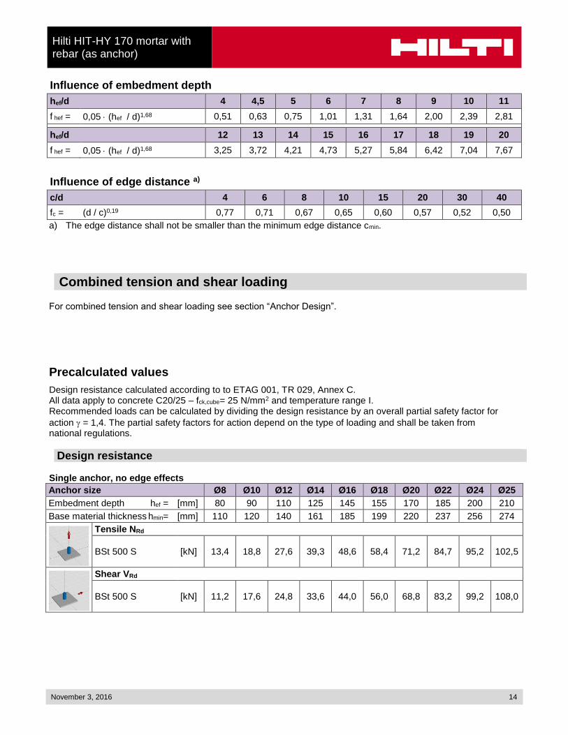
Influence of embedment depth
hef/d 4 4,5 5 6 7 8 9 10 11
f hef = 0,05 (hef / d)1,68 0,51 0,63 0,75 1,01 1,31 1,64 2,00 2,39 2,81
hef/d 12 13 14 15 16 17 18 19 20
f hef = 0,05 (hef / d)1,68 3,25 3,72 4,21 4,73 5,27 5,84 6,42 7,04 7,67
Influence of edge distance a)
c/d 4 6 8 10 15 20 30 40
fc = (d / c)0,19 0,77 0,71 0,67 0,65 0,60 0,57 0,52 0,50
a) The edge distance shall not be smaller than the minimum edge distance cmin.
Combined tension and shear loading
For combined tension and shear loading see section “Anchor Design”.
Precalculated values
Design resistance calculated according to to ETAG 001, TR 029, Annex C. All data apply to concrete C20/25 – fck,cube= 25 N/mm2 and temperature range I. Recommended loads can be calculated by dividing the design resistance by an overall partial safety factor for
action = 1,4. The partial safety factors for action depend on the type of loading and shall be taken from national regulations.
Design resistance Single anchor, no edge effects
Anchor size Ø8 Ø10 Ø12 Ø14 Ø16 Ø18 Ø20 Ø22 Ø24 Ø25
Embedment depth hef = [mm] 80 90 110 125 145 155 170 185 200 210
Base material thickness hmin= [mm] 110 120 140 161 185 199 220 237 256 274
Tensile NRd
BSt 500 S [kN] 13,4 18,8 27,6 39,3 48,6 58,4 71,2 84,7 95,2 102,5
Shear VRd
BSt 500 S [kN] 11,2 17,6 24,8 33,6 44,0 56,0 68,8 83,2 99,2 108,0

Hilti HIT-HY 170 mortar with rebar (as anchor)
15 November 3, 2016
Single anchor, min. edge distance (c = cmin)
Anchor size Ø8 Ø10 Ø12 Ø14 Ø16 Ø18 Ø20 Ø22 Ø24 Ø25
Embedment depth hef = [mm] 80 90 110 125 145 155 170 185 200 210
Base material thickness hmin= [mm] 110 120 140 161 185 199 220 237 256 274
Edge distance c = cmin= [mm] 40 50 60 70 80 90 100 110 120 125
Tensile NRd
BSt 500 S [kN] 8,0 11,2 16,4 22,7 28,3 31,7 36,6 41,7 47,0 50,4
Shear VRd
BSt 500 S [kN] 3,7 5,3 7,3 9,5 11,9 14,4 17,2 20,1 23,3 25,0
Double anchor, no edge effects, min. spacing (s = smin) (values valid for a single anchor)
Anchor size Ø8 Ø10 Ø12 Ø14 Ø16 Ø18 Ø20 Ø22 Ø24 Ø25
Embedment depth hef = [mm] 80 90 110 125 145 155 170 185 200 210
Base material thickness hmin= [mm] 110 120 140 161 185 199 220 237 256 274
Spacing s = smin= [mm] 40 50 60 70 80 90 100 110 120 125
Tensile NRd
BSt 500 S [kN] 8,2 11,5 16,8 23,9 29,6 35,5 42,2 47,9 53,9 58,0
Shear VRd
BSt 500 S [kN] 11,2 17,6 24,8 33,6 44,0 56,0 68,8 83,2 99,2 108,0