Anchor Checking Using ACI 318 Appendix D
30
GTSTRUDL Anchor Checking Using ACI 318 Appendix D Rob Abernathy CASE Center GTSUG June, 2011 Delray Beach, FL
description
Anchor Checking Using ACI 318 Appendix D. Rob Abernathy CASE Center GTSUG June, 2011 Delray Beach, FL. What is “Anchoring to Concrete”. - PowerPoint PPT Presentation
Transcript of Anchor Checking Using ACI 318 Appendix D

GTSTRUDLGTSTRUDL
Anchor Checking Using ACI 318 Appendix D
Anchor Checking Using ACI 318 Appendix D
Rob AbernathyCASE Center GTSUG June, 2011 Delray Beach, FL

GTSTRUDLGTSTRUDL
What is “Anchoring to Concrete”What is “Anchoring to Concrete”
GTSUG June, 2011GTSUG June, 2011 2
Appendix D, first added to 318 in 2002, “provides design requirements for anchors in concrete used to transmit structural loads…” This presentation is limited to the provisions that are used in anchoring base plates to a bearing surface, although Appendix D can be used in some situations of anchoring to structural members.
This presentation is based on ACI 318-05, and includes figures copied from the Appendix D commentary. Many of the formulas and techniques found in Appendix D are based on the paper “Concrete Capacity Design (CCD) …”, ACI Structural Journal, 1995, which is reference D.9 in ACI 318-05 and -08.
GTSTRUDLGTSTRUDL
Anchoring to Concrete: Terms and ConceptsAnchoring to Concrete: Terms and Concepts
GTSUG June, 2011GTSUG June, 2011 3
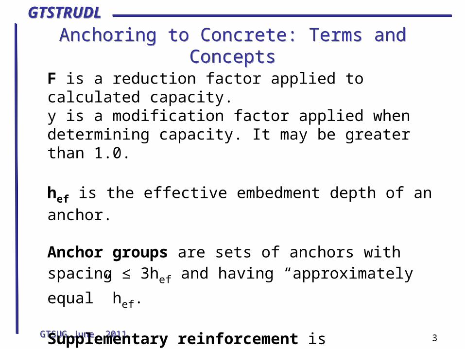
F is a reduction factor applied to calculated capacity.y is a modification factor applied when determining capacity. It may be greater than 1.0.
hef is the effective embedment depth of an anchor.
Anchor groups are sets of anchors with spacing ≤ 3hef
and having “approximately equal” hef.
Supplementary reinforcement is “reinforcement proportioned to tie a potential concrete failure prism to the structural member”, although the rules for proportioning are not defined in Appendix D.

GTSTRUDLGTSTRUDL
Terms and Concepts: Breakout/Failure ConeTerms and Concepts: Breakout/Failure Cone
GTSUG June, 2011GTSUG June, 2011 4
The major concern of Appendix D is the failure of the concrete via a “breakout” cone. Tension can cause breakout from the top surface of the concrete as shown to the left or at an edge. Shear can cause breakout on the surface through “pryout” or at an edge. Note that the area involved
extends 1.5hef from the anchor
center, hence the 3hef (1.5 + 1.5)
spacing definition of an anchor group.

GTSTRUDLGTSTRUDL
What does Appendix D cover?What does Appendix D cover?
• Anchor + concrete capacity only – no base plate provisions
• Limited to anchors 2” or less diameter and hef (effective length) of 25” or less.
• f’c of 10,000 psi for cast-in anchors and
8,000 psi for post-installed anchors.
• “Regular” arrangement of similar anchors. Not a formal requirement, but only examples of such are given.
GTSUG June, 2011GTSUG June, 2011 5
GTSTRUDLGTSTRUDL
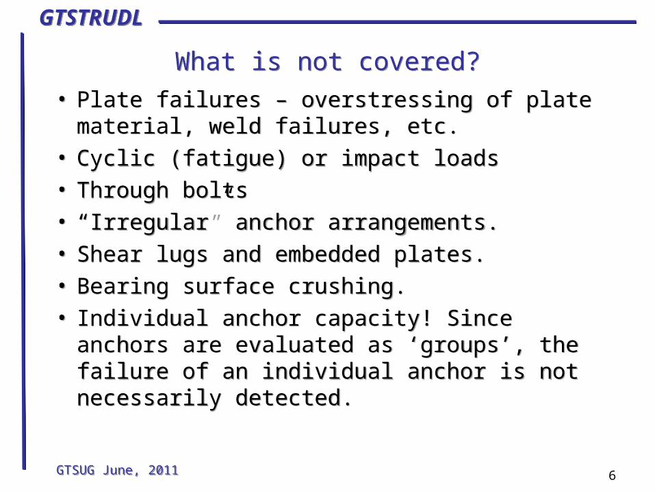
What is not covered?What is not covered?
• Plate failures – overstressing of plate material, weld failures, etc.
• Cyclic (fatigue) or impact loads• Through bolts• “Irregular” anchor arrangements.• Shear lugs and embedded plates.• Bearing surface crushing.• Individual anchor capacity! Since anchors are
evaluated as ‘groups’, the failure of an individual anchor is not necessarily detected.
GTSUG June, 2011GTSUG June, 2011 6

GTSTRUDLGTSTRUDL
Capacity CriteriaCapacity Criteria
• Seismic reduction (Section D.3.3)• Check tension (N)
– FNn ≥ Nua (D-1)
• Check shear (V)– FVn ≥ Vua (D-2)
• Check interaction if Nua > 0.2FNn and Vua >
0.2FVn:
Nua/FNn + Vua/FVn ≤ 1.2 (D-31)
• Spacing checks– D.8 requirements unless supplemental
reinforcement exists.
• Seismic reduction (Section D.3.3)• Check tension (N)
– FNn ≥ Nua (D-1)
• Check shear (V)– FVn ≥ Vua (D-2)
• Check interaction if Nua > 0.2FNn and Vua >
0.2FVn:
Nua/FNn + Vua/FVn ≤ 1.2 (D-31)
• Spacing checks– D.8 requirements unless supplemental
reinforcement exists.GTSUG June, 2011GTSUG June, 2011 7

GTSTRUDLGTSTRUDL
The checking processThe checking process
• Get characteristics of anchors, base plate and bearing surface concrete plus the location of anchors and edges.
• Loadings: Section 9.2 or Appendix C load factors
• Check edge distance and spacing if supplementary reinforcement does not exist.
• Create groups based on anchor geometry.
• Check anchor capacity for shear and tension – reduce if seismic requirement
• Determine F factors based on governing sections
• Calculate interaction value
GTSUG June, 2011GTSUG June, 2011 8

GTSTRUDLGTSTRUDL
Anchor characteristicsAnchor characteristics
• Cast-in or post-installed
• Embedment length hef
• Diameter do
• Ductility – ductile or brittle, based on test elongation or area reduction.
• Tensile strength futa
– The use of futa instead of fya is to match with
AISC LRFD design.
• Ase – effective cross-section area; manufacturer’s
value if not pdo2.
GTSUG June, 2011GTSUG June, 2011 9

GTSTRUDLGTSTRUDL
Anchor Characteristics: Cast-in anchorsAnchor Characteristics: Cast-in anchors
• Headed bolt
• Hooked bolt
• Headed stud
• Headed bolt
• Hooked bolt
• Headed stud
GTSUG June, 2011GTSUG June, 2011 10
Optional dataNp pullout strength in cracked concrete
Abrg bearing area of head if Np not specified,
for headed bolts or studs.eh width of hook or L if Np not specified, for
hooked boltsWasher – headed anchors, increases hef.

GTSTRUDLGTSTRUDL
Anchor Characteristics: Post-installed anchorsAnchor Characteristics: Post-installed anchors
• Type: UC (undercut), TC (torque-controlled), DC (displacement-controlled)
• Pullout strength Np
• Category: 1, 2 or 3 – low to high sensitivity.
• Type: UC (undercut), TC (torque-controlled), DC (displacement-controlled)
• Pullout strength Np
• Category: 1, 2 or 3 – low to high sensitivity.
GTSUG June, 2011GTSUG June, 2011 11

GTSTRUDLGTSTRUDL
Anchor Characteristics: Post-installed anchorsOptional data
Anchor Characteristics: Post-installed anchorsOptional data
• cac: Manufacturer’s critical edge distance
or taken from D.8.3.
• Vsa: Shear strength in lieu of D-20
• kc and yc,N – Concrete breakout strength
coefficient + cracked concrete modification factor. If kc from the
manufacturer is used, the specified yc,N must also be used.
• cac: Manufacturer’s critical edge distance
or taken from D.8.3.
• Vsa: Shear strength in lieu of D-20
• kc and yc,N – Concrete breakout strength
coefficient + cracked concrete modification factor. If kc from the
manufacturer is used, the specified yc,N must also be used.
GTSUG June, 2011GTSUG June, 2011 12
GTSTRUDLGTSTRUDL
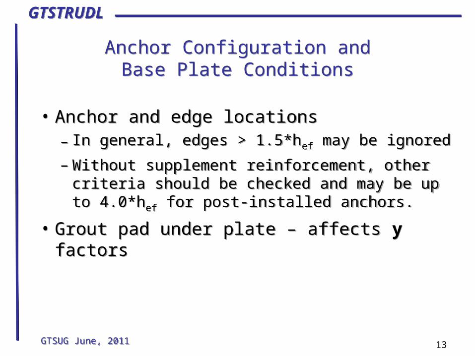
Anchor Configuration andBase Plate Conditions
Anchor Configuration andBase Plate Conditions
• Anchor and edge locations– In general, edges > 1.5*hef may be ignored
– Without supplement reinforcement, other criteria should be checked and may be up to 4.0*hef for post-installed anchors.
• Grout pad under plate – affects y factors
• Anchor and edge locations– In general, edges > 1.5*hef may be ignored
– Without supplement reinforcement, other criteria should be checked and may be up to 4.0*hef for post-installed anchors.
• Grout pad under plate – affects y factors
GTSUG June, 2011GTSUG June, 2011 13

GTSTRUDLGTSTRUDL
Concrete CharacteristicsConcrete Characteristics
• f’c• Cracked/Uncracked• Supplementary reinforcement
– Outside the scope of Appendix D in ’05. Note: ’08 adds “Anchor reinforcement” with specific design guides.
• Thickness– In general, > hef*1.333 or hef+4” for post-
installed without supplemental reinforcement.
• f’c• Cracked/Uncracked• Supplementary reinforcement
– Outside the scope of Appendix D in ’05. Note: ’08 adds “Anchor reinforcement” with specific design guides.
• Thickness– In general, > hef*1.333 or hef+4” for post-
installed without supplemental reinforcement.
GTSUG June, 2011GTSUG June, 2011 14

GTSTRUDLGTSTRUDL
Tension capacity: Section D.5Tension capacity: Section D.5
GTSUG June, 2011GTSUG June, 2011 15
Tension capacity is determined using “Section D.5 – Design requirements for tensile loading”, with four types of strength measures specified in sections D.5.1 to D.5.4. The lowest value of Nn calculated is used in
equation D-1 and its type will be used when determining F for tension.
Processing must be done on a load-by-load basis, since not all anchors will be in tension for all loads and this will affect capacity calculations, especially yec,N, the
modification factor for loading eccentricity.
GTSTRUDLGTSTRUDL
D.5.1 Steel Strength of AnchorD.5.1 Steel Strength of Anchor
GTSUG June, 2011GTSUG June, 2011 16
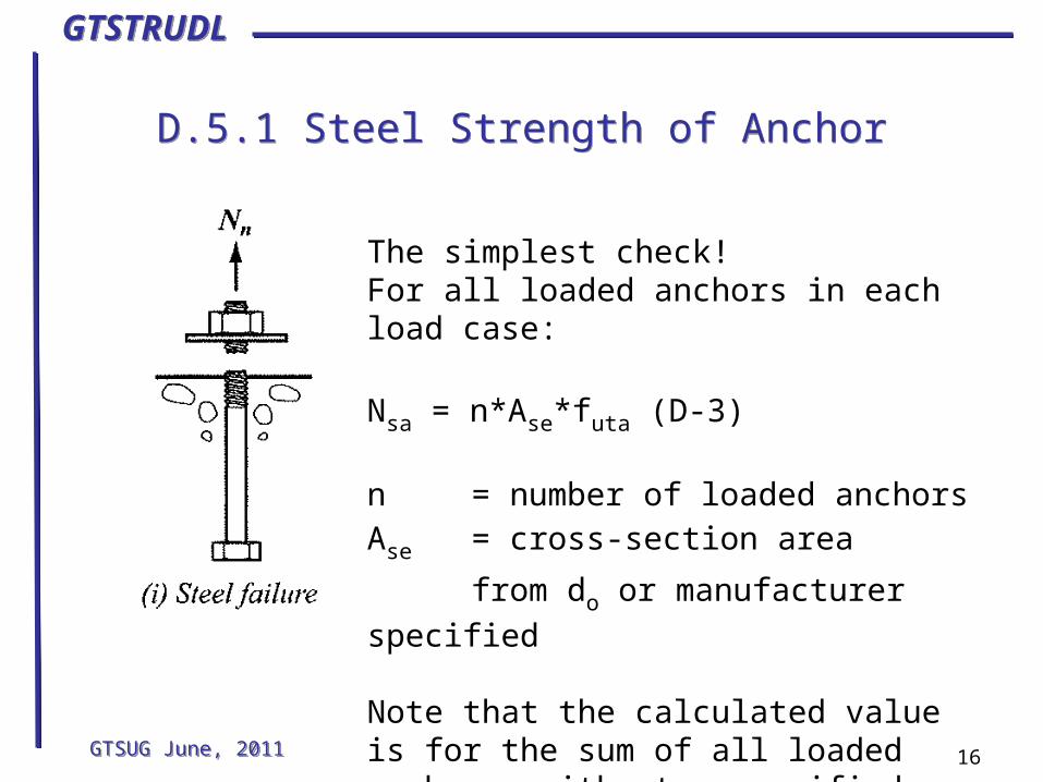
The simplest check!For all loaded anchors in each load case:
Nsa = n*Ase*futa (D-3)
n = number of loaded anchorsAse = cross-section area
from do or manufacturer specified
Note that the calculated value is for the sum of all loaded anchors, without a specified check on individual anchors.

GTSTRUDLGTSTRUDL
GTSUG June, 2011GTSUG June, 2011 17
D.5.2 Concrete BreakoutD.5.2 Concrete Breakout
Ncb = (ANc/ANco)*yec,N*yed,N*yc,N*ycp,N*Nb
yec,N: Eccentricity factor from D-9 (single anchor = 1.0)
yed,N: Edge proximity factor
yc,N: Cracked concrete factor
ycp,N: Post-installed cac reinforcement factor (cast-in = 1.0)
Nb = Concrete breakout for a single anchor, no edges
From D-7, D-8 or manufacturer’s specs

GTSTRUDLGTSTRUDL
D.5.2 Concrete Breakout: (ANc/ANco) D.5.2 Concrete Breakout: (ANc/ANco)
GTSUG June, 2011GTSUG June, 2011 18
ANco = Maximum area of single breakout cone
= 9.0*hef2
ANc , the total projected
concrete failure area of an anchor group, is affected by anchor spacing and edge distance.

GTSTRUDLGTSTRUDL
D.5.2 Concrete Breakout: yec,ND.5.2 Concrete Breakout: yec,N
GTSUG June, 2011GTSUG June, 2011 19
If eccentricity exists in both X and Y, yec,N is the product of yec,N_X
and yec,N_Y.

GTSTRUDLGTSTRUDL
D.5.3 Pullout StrengthD.5.3 Pullout Strength
GTSUG June, 2011GTSUG June, 2011 20
For each anchor in tension – no grouping:
Npn = yc,P*Np
Cast-in anchors: Np from D-15 or D-16
Np = 8*Abrg*f’c (D-15)
Np = 0.9*f’c*eh*do (D-16)
Post-installed anchors: Np specified
yc,P = 1.0 for cracked concrete
= 1.4 for uncracked concrete
GTSTRUDLGTSTRUDL
D.5.4 Concrete side-face blowoutD.5.4 Concrete side-face blowout
GTSUG June, 2011GTSUG June, 2011 21
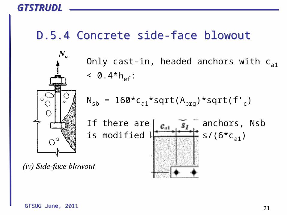
Only cast-in, headed anchors with ca1 < 0.4*hef:
Nsb = 160*ca1*sqrt(Abrg)*sqrt(f’c)
If there are multiple anchors, Nsb is modified by: 1.0 + s/(6*ca1)

GTSTRUDLGTSTRUDL
Shear capacity: Section D.6Shear capacity: Section D.6
GTSUG June, 2011GTSUG June, 2011 22
Shear capacity is determined using “Section D.6 – Design requirements for shear loading”, with three types of strength measures specified in sections D.6.1 to D.6.3. The lowest value of
Vua calculated is used in equation D-2 and its section will be used
when determining F.Processing must be done on a load-by-load basis, even
though all anchors tend to share the shear load, since yec,N, the
modification factor for loading eccentricity, will vary.If edges are present, processing for shear becomes very
complicated, since ca1, the minimum edge distance, is measured
“in the direction of the applied shear”, and may in fact be different for every anchor if in-plane rotation exists. One solution is to separate the shear into (X, Y) components and process separately, but ACI does not address this issue directly. Non-orthogonal edges would complicate the problem even more.
GTSTRUDLGTSTRUDL
D.6.1 Steel shear strengthD.6.1 Steel shear strength
GTSUG June, 2011GTSUG June, 2011 23
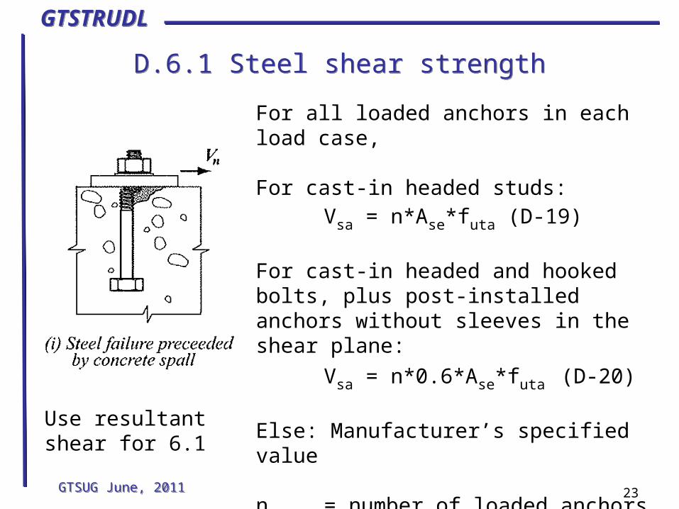
For all loaded anchors in each load case,
For cast-in headed studs:Vsa = n*Ase*futa (D-19)
For cast-in headed and hooked bolts, plus post-installed anchors without sleeves in the shear plane:
Vsa = n*0.6*Ase*futa (D-20)
Else: Manufacturer’s specified value
n = number of loaded anchorsAse = cross-section area
from do or manufacturer specified
Use resultantshear for 6.1

GTSTRUDLGTSTRUDL
D.6.2 Concrete breakout in shearD.6.2 Concrete breakout in shear
GTSUG June, 2011GTSUG June, 2011 24
Vcb = (AVc/AVco) *yec,V*yed,V*yc,V*Vb (D-22)
yec,V = Eccentricity factor, = 1.0 for single anchors
yed,V = Edge proximity factor
yc,V = Cracked concrete factor
Vb = Single anchor breakout strength in cracked concrete
This is the most complicated provision, but only applies to anchors “near” an edge, such that 4.5*ca1
3.5*sqrt(f’c)
approaches Ase*futa (D-19).
GTSTRUDLGTSTRUDL
D.6.2 (con’t)D.6.2 (con’t)
GTSUG June, 2011GTSUG June, 2011 25
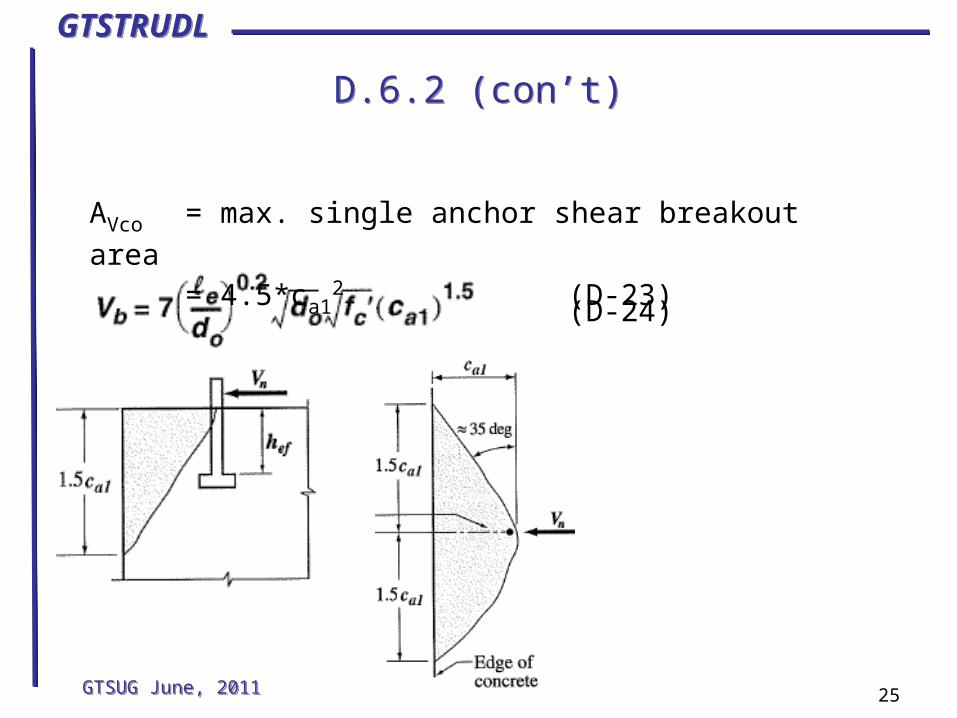
AVco = max. single anchor shear breakout area
= 4.5*ca12 (D-23)
(D-24)
GTSTRUDLGTSTRUDL
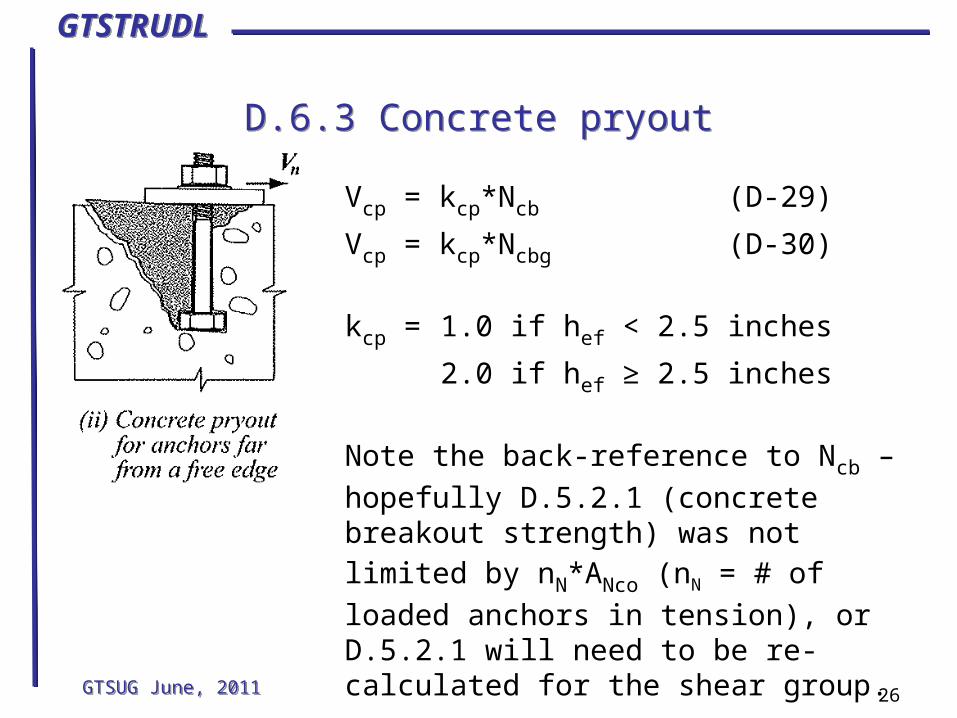
D.6.3 Concrete pryoutD.6.3 Concrete pryout
GTSUG June, 2011GTSUG June, 2011 26
Vcp = kcp*Ncb (D-29)
Vcp = kcp*Ncbg (D-30)
kcp = 1.0 if hef < 2.5 inches
2.0 if hef ≥ 2.5 inches
Note the back-reference to Ncb – hopefully
D.5.2.1 (concrete breakout strength) was not limited by nN*ANco (nN = # of loaded anchors
in tension), or D.5.2.1 will need to be re-calculated for the shear group.

GTSTRUDLGTSTRUDL
Determining F values: Section D.4.4, loads from Section 9.2
Determining F values: Section D.4.4, loads from Section 9.2
GTSUG June, 2011GTSUG June, 2011 27
Determine governing failure mode:If steel element governs,
Ductile: F = 0.75 for tension, 0.65 for shearBrittle: F = 0.65 for tension, 0.60 for shear
If concrete governs, but not D.5.3 or D.6.3, and supplementary reinforcement exists,
F = 0.75 for shear, all anchorsF = 0.75 for tension, cast-in & post-installed Cat 1
-0.10 for Category 2, -0.20 for Category 3If concrete governs but not the above conditions
F = 0.70 for shear, all anchorsF = 0.70 for tension, cast-inF = 0.65 for tension, post-installed Category 1
-0.10 for Category 2, -0.20 for Category 3

GTSTRUDLGTSTRUDL
Determining F values: Section D.4.5, loads from Appendix C
Determining F values: Section D.4.5, loads from Appendix C
GTSUG June, 2011GTSUG June, 2011 28
Determine governing failure mode:If steel element governs,
Ductile: F = 0.80 for tension, 0.75 for shearBrittle: F = 0.70 for tension, 0.65 for shear
If concrete governs, but not D.5.3 or D.6.3, and supplementary reinforcement exists,
F = 0.85 for shear, all anchorsF = 0.85 for tension, cast-in & post-installed Cat 1
-0.10 for Category 2, -0.20 for Category 3If concrete governs and no supplementary reinforcement,
F = 0.75 for shear, all anchorsF = 0.75 for tension, cast-in & post-installed Cat 1
-0.10 for Category 2, -0.20 for Category 3
GTSTRUDLGTSTRUDL
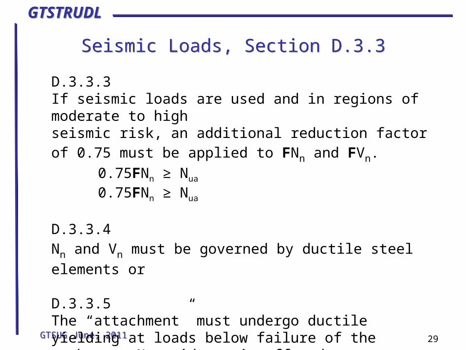
Seismic Loads, Section D.3.3Seismic Loads, Section D.3.3
GTSUG June, 2011GTSUG June, 2011 29
D.3.3.3If seismic loads are used and in regions of moderate to high seismic risk, an additional reduction factor of 0.75 must be applied to FNn and FVn.
0.75FNn ≥ Nua
0.75FNn ≥ Nua
D.3.3.4Nn and Vn must be governed by ductile steel elements or
D.3.3.5The “attachment” must undergo ductile yielding at loads below failure of the anchors. No guidance is offered as to making this determination.

GTSTRUDLGTSTRUDL
Section D.8 – Edge distances, spacings and thickness Section D.8 – Edge distances, spacings and thickness
GTSUG June, 2011GTSUG June, 2011 30
If no supplementary reinforcement exists:
Min c-to-c spacing: 4*do for cast-in, untorqued anchors
6*do for all other anchors
Minimum edge distance:Cover requirements for cast-in, untorqued6*do (or cover) for cast-in, torqued6*do for post-installed UC8*do for post-installed TC10*do for post-installed DC
Minimum concrete thickness for post-installed anchorst ≥ 1.5*hef
t ≥ hef+4”