ANAUUR - Lankota Inc · ANAUUR nstallation nstructions Auger xtensions for igh Unload Rate ohn ......
9
8/4/2017 www.lankota.com | Lankota Inc. John Deere and JD are registered trademarks of Deere & Company. Lankota is a registered trademark of Lankota Group. Page | 1 LANAUGHURK Installation Instructions Auger Extensions for High Unload Rate John Deere Combines 270 West Park Avenue Huron, SD 57350 866-526-5682
Transcript of ANAUUR - Lankota Inc · ANAUUR nstallation nstructions Auger xtensions for igh Unload Rate ohn ......

8/4/2017 www.lankota.com | Lankota Inc. John Deere and JD are registered trademarks of Deere & Company. Lankota is a registered trademark of Lankota Group.
Page | 1
LANAUGHURK
Installation Instructions Auger Extensions for High Unload Rate John Deere Combines
270 West Park Avenue
Huron, SD 57350
866-526-5682
8/4/2017 www.lankota.com | Lankota Inc. John Deere and JD are registered trademarks of Deere & Company. Lankota is a registered trademark of Lankota Group.
Page | 2
Numerical Parts List
Part Numbers Description Quantity LANAUGHUR-B Bearing Hanger 1 LANAUGHUR-C Access Cover 1 LANAUGHUR-F Auger Flighting Extension Weldment 1 LANAUGHUR-T1 Saddle Tube 1 LANAUGHUR-T2 Extension Tube 1 LANGS20 Grain Saver Door Weldment 1 LANGS24 Spring Arm 1 LANAUG295 Spring Retainer Band 2 LAN207KRRB12 Bearing 1 LAN105 Bearing Flange 2 LANAUGHUR-S Auger Spacer 5 LANAUGHURKBH Bags of Hardware 1
Each Bag Includes: RED305K 3/8”-16 x 1-1/4” Carriage Bolt 13 LAN3718 3/8”-16 Serrated Lock Nut 20 LANH217334 Spring 2 LAN18A 3/8”-16 x 1” Carriage Bolt 5 LAN161800 3/8”-16 Nylon Lock Nut 2 LANF011G 1/2”-13 x 4-1/2” Full Thread Hex Bolt 1 LANF-HN-0.500C 1/2”-13 Hex Nut 1 REDWL55 1/2” Lock Washer 1 REDB206 5/16”-18 x 1-1/2” Hex Bolt 1 LANF-HN-0.313C 5/16”-18 Hex Nut 1 LANFGCMN 5/16” Bolt Retainer Clip 9
NOTE: One extra spring is included for replacement if necessary

8/4/2017 www.lankota.com | Lankota Inc. John Deere and JD are registered trademarks of Deere & Company. Lankota is a registered trademark of Lankota Group.
Page | 3
Pictorial Parts List
LANGS20 (1) LANAUG295 (2) LANGS24 (1) LANAUGHUR-T1 (1) LANAUGHUR-T2 (1) LAN105 (2)
LANAUGHUR-B (1) LANAUGHUR-C (1) LANAUGHUR-F (1) LANH217334 (1) LANFGCMN(9) LAN207KRRB12 (1)
LAN3718 (20)
RED305K (13) LAN1618000 (2) LAN18A (5) REDB206 (1) LANF-HN-0.313C (1)
LANF-HN-0.500C (1) LANF011G (1) REDWL55 (1) LANAUGHUR-S (5) LANH217334 (1)
(Replacement/Spare)
8/4/2017 www.lankota.com | Lankota Inc. John Deere and JD are registered trademarks of Deere & Company. Lankota is a registered trademark of Lankota Group.
Page | 4
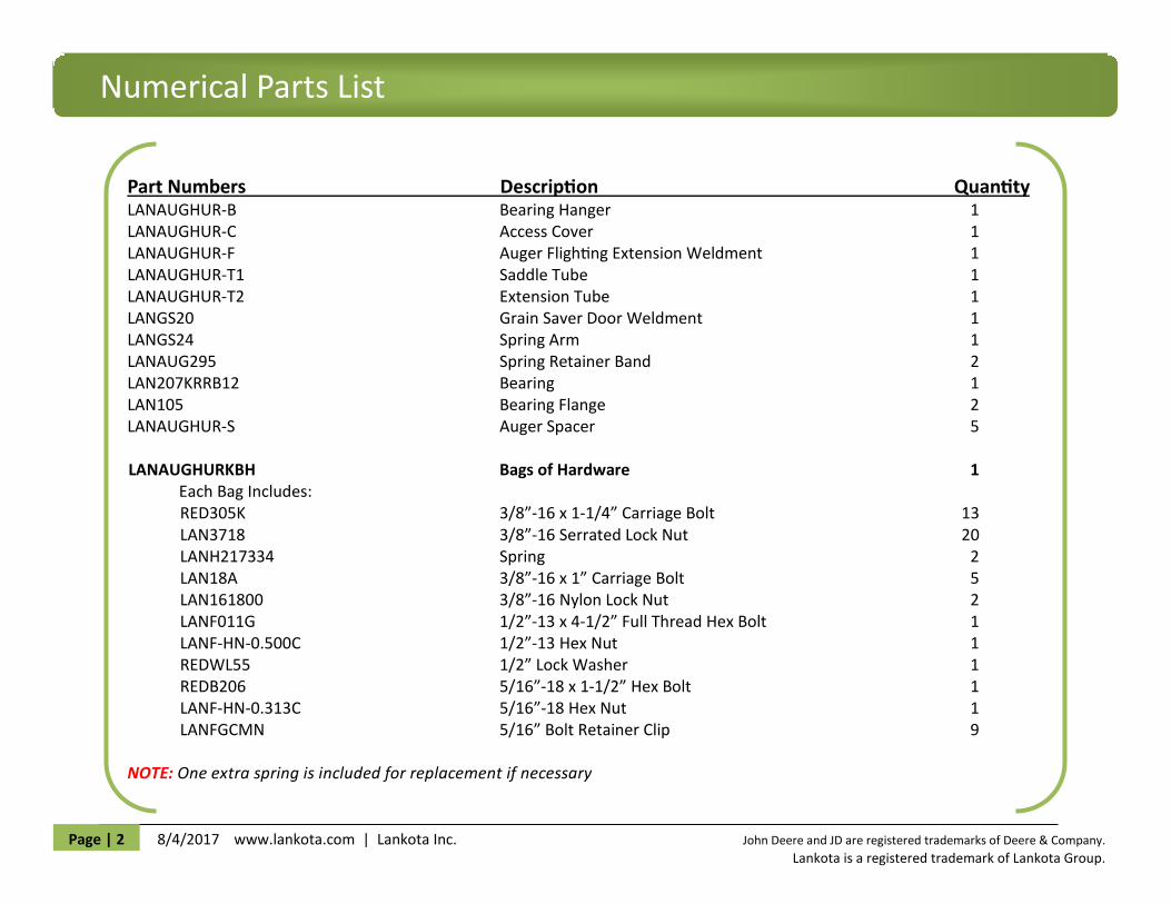
Refer to Figure 1.1
1.1 Remove the plastic spout and factory grain saver door from the
existing auger tube.
1.2 Retain all hardware for re-use later in the installation.
1.3 The factory bearing hanger and its hardware should remain fas-
tened to the existing auger tube.
Figure 1.1
1. Auger Extension Kit
8/4/2017 www.lankota.com | Lankota Inc. John Deere and JD are registered trademarks of Deere & Company. Lankota is a registered trademark of Lankota Group.
Page | 5
Figure 1.3
Figure 1.2
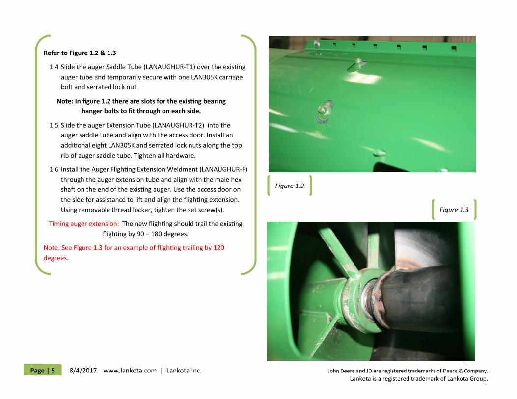
Refer to Figure 1.2 & 1.3
1.4 Slide the auger Saddle Tube (LANAUGHUR-T1) over the existing
auger tube and temporarily secure with one LAN305K carriage
bolt and serrated lock nut.
Note: In figure 1.2 there are slots for the existing bearing
hanger bolts to fit through on each side.
1.5 Slide the auger Extension Tube (LANAUGHUR-T2) into the
auger saddle tube and align with the access door. Install an
additional eight LAN305K and serrated lock nuts along the top
rib of auger saddle tube. Tighten all hardware.
1.6 Install the Auger Flighting Extension Weldment (LANAUGHUR-F)
through the auger extension tube and align with the male hex
shaft on the end of the existing auger. Use the access door on
the side for assistance to lift and align the flighting extension.
Using removable thread locker, tighten the set screw(s).
Timing auger extension: The new flighting should trail the existing
flighting by 90 – 180 degrees.
Note: See Figure 1.3 for an example of flighting trailing by 120
degrees.
8/4/2017 www.lankota.com | Lankota Inc. John Deere and JD are registered trademarks of Deere & Company. Lankota is a registered trademark of Lankota Group.
Page | 6
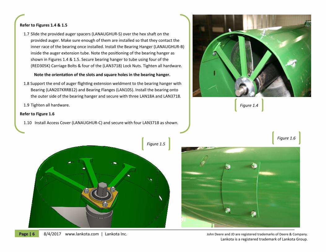
Refer to Figures 1.4 & 1.5
1.7 Slide the provided auger spacers (LANAUGHUR-S) over the hex shaft on the
provided auger. Make sure enough of them are installed so that they contact the
inner race of the bearing once installed. Install the Bearing Hanger (LANAUGHUR-B)
inside the auger extension tube. Note the positioning of the bearing hanger as
shown in Figures 1.4 & 1.5. Secure bearing hanger to tube using four of the
(RED305K) Carriage Bolts & four of the (LAN3718) Lock Nuts. Tighten all hardware.
Note the orientation of the slots and square holes in the bearing hanger.
1.8 Support the end of auger flighting extension weldment to the bearing hanger with
Bearing (LAN207KRRB12) and Bearing Flanges (LAN105). Install the bearing onto
the outer side of the bearing hanger and secure with three LAN18A and LAN3718.
1.9 Tighten all hardware.
Refer to Figure 1.6
1.10 Install Access Cover (LANAUGHUR-C) and secure with four LAN3718 as shown.
Figure 1.4
Figure 1.5
Figure 1.6

8/4/2017 www.lankota.com | Lankota Inc. John Deere and JD are registered trademarks of Deere & Company. Lankota is a registered trademark of Lankota Group.
Page | 7
2. Grain Saver Door Installation
Refer to Figure 2.1 & 2.2
1. Install the Grain Saver Weldment (LANAUGHURGS) onto the end of the auger tube as shown below using existing hardware. The two bolts
toward the end of the auger (that held the factory door on) should be tightened while four others remain loose for spout installation.
2. Install the plastic spout and snug up all bolts.
Figure 2.1 Figure 2.2

8/4/2017 www.lankota.com | Lankota Inc. John Deere and JD are registered trademarks of Deere & Company. Lankota is a registered trademark of Lankota Group.
Page | 8
Refer to Figures 2.3 & 2.4
3. On the side of the grain saver door with the weld nut, draw a vertical line 5” from the end of the spout. (Figure 2.3).
4. Along the line, measure up 2 - 5/8” from the contour line (shown in RED in Figure 2.4) of the spout and make a mark.
5. Drill a 5/8” hole in the spout where the two lines cross and install the grain saver spring arm.
Figure 2.4
Figure 2.3

8/4/2017 www.lankota.com | Lankota Inc. John Deere and JD are registered trademarks of Deere & Company. Lankota is a registered trademark of Lankota Group.
Page | 9
Installation
Refer to Figures 2.5 & 2.6
6. The drilled hole should line up with the nut welded to the grain saver door. Using the REDWL55, LANF-HN-0.500C and LANF011G install the
grain saver door arm (LANGS24).
7. A good starting point for the band is 3” behind the plastic spout (Figure 2.5).
8. Adjust LANGS24 (grain saver spring arm) so the spring length when installed is roughly 9” (the grain saver spring arm should tilt back 10-15
degrees - see Figure 2.6). Tighten all fasteners for operation.
9. Tighten the nut on the grain saver arm for operation.
Figure 2.5
Figure 2.6