Anatomic Considerations, Nomenclature, and Advanced Cross ...
15
Anatomic Considerations, Nomenclature, and Advanced Cross-sectional Imaging Techniques for Visualization of the Cranial Nerve Segments by MR Imaging Ari M. Blitz, MD a, *, Asim F. Choudhri, MD b , Zachary D. Chonka, MD a , Ahmet T. Ilica, MD a , Leonardo L. Macedo, MD c , Avneesh Chhabra, MD d , Gary L. Gallia, MD, PhD e , Nafi Aygun, MD a INTRODUCTION The 12 pairs of cranial nerves (CNs) arise directly from the brain within the cranial vault (with the exception of spinal rootlets of CN XI, which arises from the rostral cervical spine). The CNs serve a variety of highly specialized functions, including those necessary for vision, movement of the eyes and face, and identification and consump- tion of food. The branching patterns and/or prox- imity of CNs to each other at points along their course may allow localization of pathology on clinical grounds. 1 MR imaging plays an important role in the localization and identification of pathol- ogy as well as presurgical planning. A variety of modalities have been used in the imaging evalua- tion of CNs. Clinically, the first cross-sectional im- aging study to directly demonstrate the CNs was pneumoencephalography. During pneumoence- phalography, the introduction of subarachnoid air surrounding the CNs allowed for visualization of the optic, oculomotor, trigeminal, and hypo- glossal nerves within the basal cisterns. 2 The a Division of Neuroradiology, The Russell H. Morgan Department of Radiology and Radiologic Science, The Johns Hopkins Hospital, Phipps B-100, 600 North Wolfe Street, Baltimore, MD 21287, USA; b Department of Radiology, University of Tennessee Health Science Center, Le Bonheur Neuroscience Institute, Le Bonheur Chil- dren’s Hospital, 848 Adams Avenue-G216, Memphis, TN 38103, USA; c Cedimagem/Alliar, Diagnostic Center, 150 Centro, Juiz de Fora, Minas Gerais 36010-600, Brazil; d The University of Texas Southwestern, 5323 Harry Hines Blvd, Dallas, TX 75390-9178, USA; e Department of Neurosurgery, Neurosurgery Skull Base Surgery Center, The Johns Hopkins Hospital, Phipps 101, 600 North Wolfe Street, Baltimore, MD 21287, USA * Corresponding author. E-mail address: [email protected] KEYWORDS Cranial nerve segments Cross-sectional imaging MR imaging KEY POINTS The cranial nerves (CNs) pursue a complex course through tissues with widely varying MR imaging signal characteristics as they extend from brainstem nuclei into the fluid-filled subarachnoid spaces and ultimately pass through the skull base to exit the cranium. In turn, the reported success of the variety of available MR imaging sequences for visualization of the CNs depends largely on their anatomic context at the point of evaluation. Consideration of the general segmental architecture of the CNs aids in evaluation of patients with pathologic conditions affecting or adjoining their course. Neuroimag Clin N Am 24 (2014) 1–15 http://dx.doi.org/10.1016/j.nic.2013.03.020 1052-5149/14/$ – see front matter Ó 2014 Elsevier Inc. All rights reserved. neuroimaging.theclinics.com
Transcript of Anatomic Considerations, Nomenclature, and Advanced Cross ...

Anatomic Considerations,Nomenclature, and AdvancedCross-sectional ImagingTechniques for Visualization ofthe Cranial Nerve Segments byMR Imaging
Ari M. Blitz, MDa,*, Asim F. Choudhri, MDb,Zachary D. Chonka, MDa, Ahmet T. Ilica, MDa,Leonardo L. Macedo, MDc, Avneesh Chhabra, MDd,Gary L. Gallia, MD, PhDe, Nafi Aygun, MDaKEYWORDS
� Cranial nerve segments � Cross-sectional imaging � MR imaging
KEY POINTS
� The cranial nerves (CNs) pursue a complex course through tissues with widely varying MR imagingsignal characteristics as they extend from brainstem nuclei into the fluid-filled subarachnoid spacesand ultimately pass through the skull base to exit the cranium.
� In turn, the reported success of the variety of available MR imaging sequences for visualization ofthe CNs depends largely on their anatomic context at the point of evaluation.
� Consideration of the general segmental architecture of the CNs aids in evaluation of patients withpathologic conditions affecting or adjoining their course.
INTRODUCTION
The 12 pairs of cranial nerves (CNs) arise directlyfrom the brain within the cranial vault (with theexception of spinal rootlets of CN XI, which arisesfrom the rostral cervical spine). The CNs serve avariety of highly specialized functions, includingthose necessary for vision, movement of theeyes and face, and identification and consump-tion of food. The branching patterns and/or prox-imity of CNs to each other at points along theircourse may allow localization of pathology on
a Division of Neuroradiology, The Russell H. Morgan DeJohns Hopkins Hospital, Phipps B-100, 600 North WolfeRadiology, University of Tennessee Health Science Centerdren’s Hospital, 848 Adams Avenue-G216, Memphis, TN150 Centro, Juiz de Fora, Minas Gerais 36010-600, BrHarry Hines Blvd, Dallas, TX 75390-9178, USA; e DepartmeCenter, The Johns Hopkins Hospital, Phipps 101, 600 Nor* Corresponding author.E-mail address: [email protected]
Neuroimag Clin N Am 24 (2014) 1–15http://dx.doi.org/10.1016/j.nic.2013.03.0201052-5149/14/$ – see front matter � 2014 Elsevier Inc. All
clinical grounds.1 MR imaging plays an importantrole in the localization and identification of pathol-ogy as well as presurgical planning. A variety ofmodalities have been used in the imaging evalua-tion of CNs. Clinically, the first cross-sectional im-aging study to directly demonstrate the CNs waspneumoencephalography. During pneumoence-phalography, the introduction of subarachnoidair surrounding the CNs allowed for visualizationof the optic, oculomotor, trigeminal, and hypo-glossal nerves within the basal cisterns.2 The
partment of Radiology and Radiologic Science, TheStreet, Baltimore, MD 21287, USA; b Department of, Le Bonheur Neuroscience Institute, Le Bonheur Chil-38103, USA; c Cedimagem/Alliar, Diagnostic Center,azil; d The University of Texas Southwestern, 5323nt of Neurosurgery, Neurosurgery Skull Base Surgeryth Wolfe Street, Baltimore, MD 21287, USA
rights reserved. neuroimaging.theclinics.com

Blitz et al2
advent of CT enabled visualization of the region ofthe CNs with a greater degree of detail and withinjection of intrathecal contrast; the CNs werevisualized as linear filling defects within the sub-arachnoid space.3 In both pneumoencephalogra-phy and CT cisternography, visualization wasprincipally limited to the cisternal/subarachnoidcourse of the CNs and pathology was impliedby alterations in the adjacent osseous structures.With the advent of MR imaging, cross-sectionalexamination of the structures of the head andneck without ionizing radiation became possible,with the ability to acquire images in any arbitraryplane allowing for the examination to be tailoredto the CN in question. MR imaging is now thestandard mode of imaging of the CNs and is thefocus of this article.
TECHNICAL CONSIDERATIONS FOR MRIMAGING ACQUISITION FIELD STRENGTH
Fischbach and colleagues4 studied T2-weightedspin-echo imaging of the CNs at 1.5T and 3T, thetwo most commonly available field strengths ofclinical MR imaging units, and found that imagesacquired at higher spatial resolution on the 3Tscanner nonetheless also had higher clarity andsignal-to-noise ratio. The detection of perineuralspread of neoplastic disease in the face initiallynot detected on 1.5T evaluation was possible onrepeat examination at 3T.5 Such results are notgenerally surprising because the tissue discrimina-tion generally improvedwith higher field strengths.6
Although 3T evaluation is generally preferred over1.5T evaluation, diagnostic images may be ob-tained at either field strength, in particular when3T MR imaging is not available, of questionablesafety, or otherwise deemed inappropriate.
COIL CHOICE
Various approaches to coil choice andcombinationhavebeenadvocated7althoughphased-arrayhead
Fig. 1. Axial CISS images through the lower midbrain aisotropic resolution. The proximal cisternal CN IV, the obis progressively less well visualized as voxel size increases.
coils are typically used in the clinical setting and areadequateformostapplications.
VOXEL SIZE AND COVERAGE
Thin-section imaging significantly improves de-tection of the CNs8 although visualization of thecisternal trochlear (CN IV), abducens (CN VI), andaccessory (CN XI) nerves may remain challenging.Due to its small caliber and proximity to multiplevascular structures, visualization of CN IV is par-ticularly dependent on the spatial resolution ofthe sequences acquired. Choi and colleagues9
compared conventional resolution (0.67 mm �0.45 mm � 1.4 mm) to high-resolution (0.3 mm �0.3 mm � 0.25 mm) imaging for detection of thecisternal trochlear nerve and found that the rateat which the nerve could probably or definitely beidentified rose significantly from approximately23% to 100%. Fig. 1 demonstrates visualizationof the trochlear nerve on 0.4-mm, 0.5-mm, and0.6-mm isotropic constructive interference in thesteady-state (CISS) images. Although increasingspatial resolution may improve visualization ofsmall structures, the trade-off with respect tolength of acquisition, reduced coverage, and/ordecreased signal-to-noise ratio renders optimalcoverage in all cases difficult. In the authors’ prac-tice, multiple 3-D sequences are typically usedand include CISS imaging for the highest spatialresolution acquisition. The typical CISS acquisitionincludes 0.6-mm isotropic voxels with coverage ofthe entirety of the posterior fossa, skull base, andupper face. In select cases where CN IV palsyhas been clinically diagnosed, a higher spatial res-olution is often used.
2-D VERSUS 3-D IMAGING
Initially, MR imaging tailored to the CNs requiredcareful attention to 2-D slice angulation to bestdemonstrate the CN in question.10 Modern MRimaging equipment allows 3-D acquisition from
cquired at (A) 0.4-mm, (B) 0.5-mm, and (C) 0.6-mmliquely oriented structure marked with an arrow (A),

Magnetic Resonance Imaging 3
which post hoc reconstruction in multiple planescan be created, often better demonstrating theCNs.8,11,12 One study of the cisternal componentsof the CNs in the cerebellopontine angle cisternwith fast spin-echo technique found that 3-D im-aging was superior to 2-D imaging due to suppres-sion of flow artifacts and thinner sections andsuggested that MR imaging evaluation of the cis-terns be performed with 3-D technique.13 Whenisotropic 3-D images are acquired, post hoc re-constructions can be made in any arbitrary plane,which is often useful in evaluating the complexanatomy of the CNs and surrounding structures.
INJECTION OF INTRAVENOUS CONTRASTAGENTS
The central nervous system (CNS) components ofthe CNs (including the entirety of the ophthalmic(CN I) and optic (CN II) nerves, which are properlytracts of the CNS rather than nerves per se) are atleast partly isolated from the contents of the blood-stream by the blood-brain barrier and do not nor-mally demonstrate visible contrast enhancement.The components of the CNs in the peripheral ner-vous system (PNS) are likewise separated by theblood-nerve barrier. When there is disruption ofthe blood-nerve barrier or blood-brain barrier, it isdetected by the presence of an increase in intensityon postcontrast MR images with T1 weighting.Perhaps owing to lack of a similar barrier mecha-nism or increased blood flow, enhancement ofthe ganglia of the CNs may be detected as a phys-iologic finding.14 Additionally, a circumneural arte-riovenous plexus surrounds portions of the CNs inthe interdural and foraminal regions of the skullbase. Enhancement of the arteriovenous plexusmay be seen, for instance, in the region of the tym-panic and mastoid segments of the facial nerve(CN VII) in addition to the region of the geniculateganglion.15 Enhancement in the other CN compo-nents is pathologic. When present pathologicenhancement aids in the detection/localization ofpathologic conditions of the CNs such asneoplastic, infectious, or inflammatory diseases.16
Fig. 2. Anatomic segments of the CNs with surround-ing tissue (a, nuclear; b, parenchymal fascicular; c,cisternal; d, dural cave; e, interdural; f, foraminal;and g, extraforaminal).
NOMENCLATURE
International consensus on anatomic nomencla-ture has been established in the Terminologia Ana-tomica.17 The accepted terms for the CNs areolfactory nerve (CN I), optic nerve (CN II), oculomo-tor nerve (CN III), trochlear nerve (CN IV), trigeminalnerve (CN V), abducens or abducent nerve (CN VI),facial nerve (CN VII), vestibulocochlear nerve (CNVIII), glossopharyngeal nerve (CN IX), vagus nerve(CN X), accessory nerve (CN XI), and hypoglossal
nerve (CN XII). The system defines multiple namedsubcomponents of the CNs by function. Struc-tures with a single function and without branches,such as CN VI, receive no further subclassifica-tion. The international nomenclature incompletelyserves the needs of a radiologist or clinician. Forinstance, lesions in various locations along thecourse of CN VI, although presenting with a similarclinical deficit of abduction of the globe, may havevastly differing differential diagnostic and clinicalimplications. Therefore, the authors propose asystematic method of segmental imaging evalua-tion of the CNs.
ANATOMIC SEGMENTS
After emerging from the brain, each of the CNscourses through the cerebral spinal fluid (CSF)before it traverses the meninges, extendingthrough an associated skull base foramen toemerge into the head and neck. Along this path,the nerves are surrounded by CSF in the subarach-noid space, venous blood in the interdural com-partment, bone within the skull base foramina,and various soft tissues after exiting from the skull.Although the anatomic course of each of the CNs isdifferent, some fundamental anatomic consider-ations are sufficiently similar to allow a systematicclassification of different segments, which sharesimilar imaging properties (Fig. 2). General ana-tomic and imaging considerations for each seg-ment follow. Selected information on pathology isincluded for illustrative purposes, although a com-prehensive description of pathology affecting eachsegment is beyond the scope of this article.
a. Nuclear Segment
Anatomic considerationsThe CN nuclei contain the cell bodies of neuronsthat either give rise to the efferent fibers, which
Blitz et al4
exit the brainstem or receive afferent input. The CNnuclei extend from the midbrain (CN III) craniallyinto the rostral cervical spine caudally (CNXI).18,19 The afferent nuclei generally rest lateraland dorsal to their efferent counterparts. Nucleiare further separated by their functional and evolu-tionary relationships from the somatic, branchial,and visceral (autonomic)motor nuclei. The visceral,somatic, and special sensory nuclei are arranged incolumns approximately medial to lateral.20
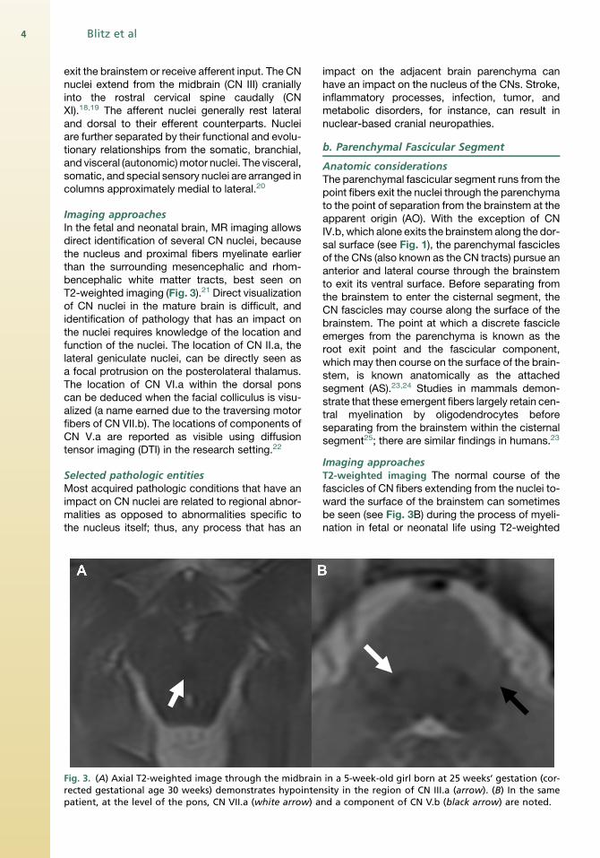
Imaging approachesIn the fetal and neonatal brain, MR imaging allowsdirect identification of several CN nuclei, becausethe nucleus and proximal fibers myelinate earlierthan the surrounding mesencephalic and rhom-bencephalic white matter tracts, best seen onT2-weighted imaging (Fig. 3).21 Direct visualizationof CN nuclei in the mature brain is difficult, andidentification of pathology that has an impact onthe nuclei requires knowledge of the location andfunction of the nuclei. The location of CN II.a, thelateral geniculate nuclei, can be directly seen asa focal protrusion on the posterolateral thalamus.The location of CN VI.a within the dorsal ponscan be deduced when the facial colliculus is visu-alized (a name earned due to the traversing motorfibers of CN VII.b). The locations of components ofCN V.a are reported as visible using diffusiontensor imaging (DTI) in the research setting.22
Selected pathologic entitiesMost acquired pathologic conditions that have animpact on CN nuclei are related to regional abnor-malities as opposed to abnormalities specific tothe nucleus itself; thus, any process that has an
Fig. 3. (A) Axial T2-weighted image through the midbrainrected gestational age 30 weeks) demonstrates hypointenpatient, at the level of the pons, CN VII.a (white arrow) a
impact on the adjacent brain parenchyma canhave an impact on the nucleus of the CNs. Stroke,inflammatory processes, infection, tumor, andmetabolic disorders, for instance, can result innuclear-based cranial neuropathies.
b. Parenchymal Fascicular Segment
Anatomic considerationsThe parenchymal fascicular segment runs from thepoint fibers exit the nuclei through the parenchymato the point of separation from the brainstem at theapparent origin (AO). With the exception of CNIV.b, which alone exits the brainstem along the dor-sal surface (see Fig. 1), the parenchymal fasciclesof the CNs (also known as the CN tracts) pursue ananterior and lateral course through the brainstemto exit its ventral surface. Before separating fromthe brainstem to enter the cisternal segment, theCN fascicles may course along the surface of thebrainstem. The point at which a discrete fascicleemerges from the parenchyma is known as theroot exit point and the fascicular component,which may then course on the surface of the brain-stem, is known anatomically as the attachedsegment (AS).23,24 Studies in mammals demon-strate that these emergent fibers largely retain cen-tral myelination by oligodendrocytes beforeseparating from the brainstem within the cisternalsegment25; there are similar findings in humans.23
Imaging approachesT2-weighted imaging The normal course of thefascicles of CN fibers extending from the nuclei to-ward the surface of the brainstem can sometimesbe seen (see Fig. 3B) during the process of myeli-nation in fetal or neonatal life using T2-weighted
in a 5-week-old girl born at 25 weeks’ gestation (cor-sity in the region of CN III.a (arrow). (B) In the samend a component of CN V.b (black arrow) are noted.
Magnetic Resonance Imaging 5
imaging, because the tightly packed layers ofmature myelin around the nerve fibers have adecreased water content compared with the sur-rounding incompletely myelinated parenchyma.21
The fascicles are not typically visualized on stan-dard anatomic imaging in patients who arematurely myelinated but may be outlined by path-ologic conditions. In the research realm, advancesin high-resolution imaging shows promise for moreclear depiction of the fascicular segments athigher field strengths than those currently usedclinically.26 Likewise, the root exit point and ASare not readily appreciated on modern clinical im-aging and must be inferred by comparison toanatomic references.
Diffusion tensor imaging DTI is a technique thatallows identification of fiber tracts within the brainparenchyma by virtue of the manner in which theyconstrain water diffusion. The technique has beenused with limited success for visualization of theCN fascicles, largely due to their small size. Thetracts associated with CN II and CN III.b are visu-alized with success.27 In one patient with CN IIIpalsy, abnormal signal in the region of CN III.bnot well seen on standard imaging was demon-strated with thin-section DTI.28 In the researchsetting, multishot diffusion-weighted imagingwith periodically rotated overlapping parallel lineswith enhanced reconstruction (PROPELLER) hasbeen suggested to improve visualization of thevisualization of the fascicular component of the
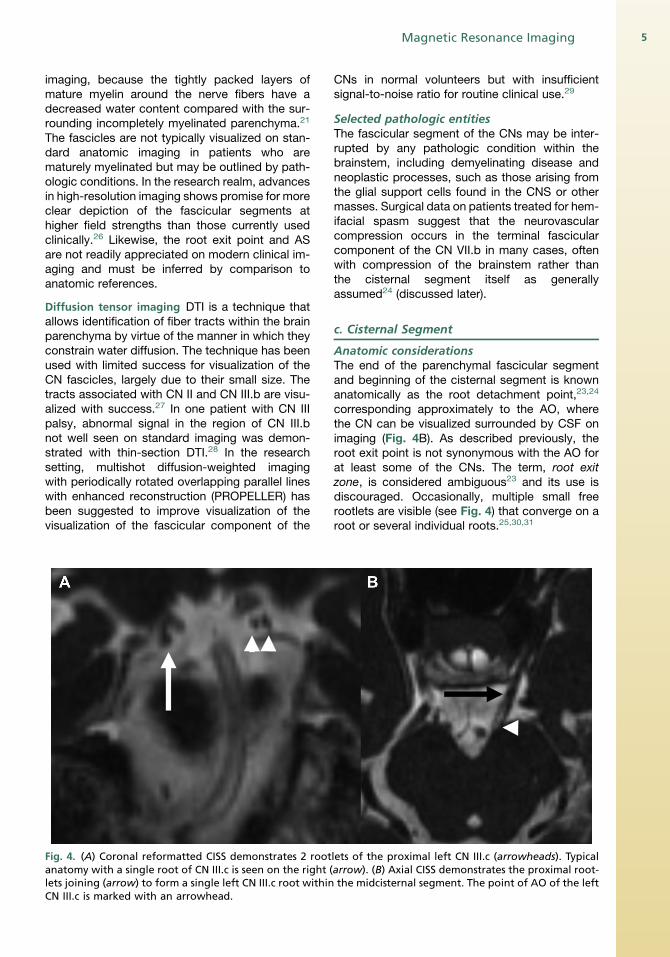
Fig. 4. (A) Coronal reformatted CISS demonstrates 2 rootanatomy with a single root of CN III.c is seen on the right (lets joining (arrow) to form a single left CN III.c root withinCN III.c is marked with an arrowhead.
CNs in normal volunteers but with insufficientsignal-to-noise ratio for routine clinical use.29
Selected pathologic entitiesThe fascicular segment of the CNs may be inter-rupted by any pathologic condition within thebrainstem, including demyelinating disease andneoplastic processes, such as those arising fromthe glial support cells found in the CNS or othermasses. Surgical data on patients treated for hem-ifacial spasm suggest that the neurovascularcompression occurs in the terminal fascicularcomponent of the CN VII.b in many cases, oftenwith compression of the brainstem rather thanthe cisternal segment itself as generallyassumed24 (discussed later).
c. Cisternal Segment
Anatomic considerationsThe end of the parenchymal fascicular segmentand beginning of the cisternal segment is knownanatomically as the root detachment point,23,24
corresponding approximately to the AO, wherethe CN can be visualized surrounded by CSF onimaging (Fig. 4B). As described previously, theroot exit point is not synonymous with the AO forat least some of the CNs. The term, root exitzone, is considered ambiguous23 and its use isdiscouraged. Occasionally, multiple small freerootlets are visible (see Fig. 4) that converge on aroot or several individual roots.25,30,31
lets of the proximal left CN III.c (arrowheads). Typicalarrow). (B) Axial CISS demonstrates the proximal root-the midcisternal segment. The point of AO of the left

Blitz et al6
The proximal nerves in this segment are coveredby pia mater32 and surrounded by CSF within thesubarachnoid space. In the cisternal segment,the CNs may adjoin arterial or venous structuresas well as the arachnoidal septae. Arterial orvenous structures may directly abut, surround, oreven divide the cisternal components of theCNs.33 The cisternal nerve roots extend towardthe porus of the dural cave segment (describedlater) (Fig. 5).The zone of transition between the oligodendro-
cyte-myelinated CNS and the Schwann cell–myelinated PNS is called the CNS-PNS transitionalzone (TZ) (sometimes given the eponym Ober-steiner-Redlich zone). The TZ was initially de-scribed as a thinning of the myelin sheaths ofspinal nerves just before the junction of the dorsalroot and the cord,34 and the CNS component ofthe nerve proximal to this point is thought moreprone to irritation. This point of transition is visibleto the neurosurgeon through the operating micro-scope, because pia mater can be seen coveringthe centrally myelinated CNS component.32
The length of the centrally myelinated portion ofthe cisternal segment and, therefore, the site of theTZ varies between the CNs. Among CNs III–XII (asreported by Lang32) the TZ is approximately 1 mmor less from the AO at the surface of the brainstemfor CNs IV, V (motor root only), VI, IX, X, and XI.The other CNs vary significantly in the length of theCNS component/location of the TZ. The TZ ofCN III.c is typically located 1.9 mm (range 1.0–4.0 mm) from the AO; the TZ of CN VII.c is located2.1 mm (range 0.5–4.0 mm) from the AO; the TZfor the sensory root of CN V.c is located on average3.6mm(range2.0–6.0mm) fromtheAO.The longestcentrally myelinated cisternal component of a CN is
Fig. 5. (A) Axial CISS image demonstrates CN V.c (black arrof CSF within the subarachnoid space extending from the penter the trigeminal cistern within the Meckel cave as CNCN IX.c (black arrow) extends through the jugular porus inforamen on precontrast CISS. (C) Significant variation is seesegment; compare the extent of CSF evagination to that
that of CNVIII.c, with the TZ locatedmost often at ornear the porus acousticus, approximately 10.0 mmfrom the brainstem (range 6.0–15.0 mm).32
Imaging approachesCN evaluation in the cisternal segment most oftendepends on negative contrast with a heavilyT2-weighted appearance of CSF, an approachsometimes termed, magnetic resonancecisternography.Although the cisternal CNs are generally well
visualized, reports of visualization of CN IV.c havebeen variously reported as inconsistent35 to excel-lent,9 depending on technique and owing to itssmall size. Visualization is significantly improvedwith voxel sizes less than the diameter of thenerve.9 The site of the TZ, although visible to neu-rosurgeons through the operating microscope,32
is not readily identifiable through imaging alone,and its approximate location must be inferredthrough knowledge of the relevant CN anatomy.
Spin-echo T2-weighted imaging Early MR imagingexperience with imaging of the cisternal CNs with2-D heavily T2-weighted turbo spin-echo imagingusing peripheral pulse gating to minimize CSFflow artifacts was successful, particularly in visual-izing CNs I, II, III, VII, and VIII.36 Subsequentstudies demonstrated a significant advantage indetection of the CNs with 3-D compared with2-D fast spin-echo sequences.13 The addition ofdriven equilibrium radiofrequency reset pulse(DRIVE) to turbo spin-echo 3-D imaging has beenshown to reduce CSF flow artifacts with lowerscan times.37 Comparison of 3-D fast asymmetricspin-echo and 3-D CISS imaging of the cerebello-pontine angle cistern by one group of investigators
ow) as a filling defect surrounded by T2 hyperintensityons (P) through the porus trigeminus (arrowheads) toV.d (white arrow). (B) At the level of the medulla (M)to a small dural cave (white arrow) of the right jugularn from patient to patient in the size of the dural cave
seen in (B).

Magnetic Resonance Imaging 7
favored 3-D fast asymmetric spin-echo due to“more prominent flow ghosts and magnetic sus-ceptibility artifacts” on CISS.38
Steady-state free precession imaging High-reso-lution steady-state free precession (SSFP) se-quences with a heavily T2-weighted appearancehave become the mainstay of visualization of thecisternal component of the CNs39 since theirintroduction by Casselman and colleagues.40
Several studies have assessed visualization ofthe CNs in the cisternal segment.35,41 3-DCISS11,35 and the analogous 3-D fast imaging us-ing steady-state acquisition (FIESTA)12 have beenshown to be superior to 2-D T2-weighted imagesfor the cisternal CNs. Additionally, comparison ofCISS to 3-D magnetization-prepared rapidgradient echo (MP-RAGE), a T1-weighted 3-Dtechnique, has favored CISS.11 In patients under-going surgery for neurovascular compression ofCN V.c, comparison of CISS to magnetic reso-nance angiography (MRA) suggested that CISSmore accurately predicts intraoperative findingswith respect to the relationship of vascular struc-tures to the CN.42
Although commonly thought of as a T2-weighted technique, CISS and FIESTA-C are fully
Fig. 6. (A) On axial precontrast CISS, the right CN VI.c (blapontine cistern indenting the left ventral pons (P). The loadministration of intravenous contrast, the left CN VI.e (confluence. As seen in the precontrast image, right CN VI.creflecting slight physiologic asymmetry in the cranial-caudthe inner layer of dura (black arrowheads) is now clear, wgioma into the interdural space adjacent to CN VI.e. The inouter periostial layer of dura is applied, denoting the oupatient presented with left-sided facial pain and decreaCN V.c (not shown). Extraocular movements were intact.
refocused (balanced) steady-state sequencesthat demonstrate both T2 and T1 components.43
This combination of weightings is ideal for theevaluation of the CNs because it allows bothhigh spatial resolution with suppression of CSFflow artifacts and the use of contrast agents(Fig. 6). The use of contrast-enhanced CISS im-ages for evaluation of cisternal masses has beenproposed by Shigematsu and colleagues,44 whosuggested that the technique could reveal the ac-curate location of CN VII.c and CN VIII.c relative tocerebellopontine angle masses.
Diffusion tensor imaging Hodaie and colleagues27
assessed visualization of the CNs, finding that eval-uation of the lower cisternal CNs was particularlychallenging. DTI has been used to determine thelocation of CN VII.c and CN VIII.c adjacent to largevestibular schwannomas in the cerebellopontineangle cistern.45,46 In addition to information on thelocation of the cisternal components of the CNs,DTI reveals alterations in the coherence of waterdiffusion (fractional anisotropy) and has beenshown to demonstrate significantly decreased frac-tional anisotropy in CN V.c on the side affected bytrigeminal neuralgia47 due to neurovascularcompression.
ck arrow) is noted. A mass (asterisk) fills the left pre-cation of the left CN VI.c is ambiguous. (B) After thewhite arrow) is clearly seen in the petroclival venous(black arrow) has not yet pierced the dura at this level,al location of CN VI.d. The relationship of the mass toithout evidence of extension of the presumed menin-ner table of the skull (white arrowheads) to which theter margin of the interdural space, is also noted. Thesed facial sensation due to compression of the left

Blitz et al8
Selected pathologic entitiesThere are several clinical implications of the loca-tion of the TZ within the cisternal segment formost of the CNs. CN injuries distal to the TZ (ie,within the PNS) have different clinical implicationsfrom proximal CNS injuries. The PNS may regen-erate with near-normal function, unlike the CNS,where a gliotic response to injury and persistentloss of axons is normal.48 Because glial cells differbetween the CNS and PNS pathology, the TZforms a boundary for differential diagnostic con-siderations as well. Because Schwann cells arefound only in the PNS, schwannomas likewiseare found only distal to the TZ. In cases of vestib-ular schwannomas, for instance,49 because the TZfor CN VIII is often found at or near the porusacousticus, the diagnosis of vestibular schwan-noma is unlikely for masses located within the cer-ebellopontine angle cistern without involvement ofthe internal auditory canal.The basal cisterns contain numerous arterial and
venous structures. Since it was first demonstratedby Janetta50 that neurovascular compressioncould cause trigeminal neuralgia and that neuro-surgical decompression could result in relief frompain, several similar syndromes of neurovascularconflict have been identified. In these syndromes,grouped together as the hyperactive dysfunctionalsyndromes, irritation or injury to the cisternalsegment of the CNs from direct contact withvascular structures is hypothesized. Although hy-peractive dysfunctional syndromes may arise dueto compression of any segment of a CN, the cen-trally myelinated components of the nerve aremore vulnerable to such syndromes. In particular,trigeminal neuralgia, hemifacial spasm, and vago-glossopharyngeal neuralgia have been associatedwith neurovascular compression of CN V.c, CNVII.c, and CN IX/CN X.c, respectively. The suscep-tibility of these nerves to neurovascular compres-sion is thought proportionate to the length of thecentrally myelinated component within thecistern.51
Readers should be aware that neurovascularcontact is common in the absence of the symp-toms discussed previously. One study found neu-rovascular contact with CN V.c is seen in 49% andCN VII.c in 79% of asymptomatic individuals.52
Additionally, a surgical series of microvasculardecompression of CN VII for hemifacial spasmdemonstrated compression in the 74% of casesnot in CN VII.c but rather the attached segmentdistal segment of CN VII.b.24 Although imagingmay predict the intraoperative findings in many pa-tients,42 false-negative and false-positive casesare common.53 As discussed previously, the mea-surement of fractional anisotropy with DTI has
been reported as abnormal in trigeminal neuralgiaand may increase specificity when neurovascularcompression of CN V.c is suspected.47 Such anapproach is less likely to be helpful for CNs ofsmaller diameter due to spatial resolution and cur-rent system limitations.
d. Dural Cave Segment
Anatomic considerationsAs the CNs leave the intracranial compartment,they transit several complex anatomic spaces.The dural cave segment is surrounded by an evag-ination of the arachnoid membrane within the inner(variously known as the lamina propria, cerebral,or meningeal) layer of the dura and its opening iscalled the porus (see Fig. 5). The dural cave formsthe region of transition from the cisternal segmentcentrally to the interdural segment distally. Thesegment is variable from CN to CN and may alsovary in prominence from individual to individual(see Fig. 5). In this regard, CN V.d that resideswithin the Meckel cave is the most familiar andprovides an archetype of the relevant anatomicconsiderations. Each of the CNs makes a similartransition, with the dural cave of CN VI, forinstance, also formed by an evagination of the in-ner layer of dura lined by arachnoid membrane.54
Generically, the location where the nerve passesout of the subarachnoid space and is no longer sur-rounded by CSF is termed, the subarachnoidangle.55 For CN V.d, the arachnoidmembrane typi-cally terminates as perineurium distal to the poste-riormargin of the gasserian ganglion.56 The point atwhich the arachnoid becomes adherent to the gan-glion and its distal divisions is variable, however;thus, the volume and extent of the trigeminalcistern are variable. Although this cistern closelyapproximates the dimensions of the Meckel cave,and for the purposes of imaging is defined as theregion with visible CSF surrounding the CN V, thetwo are not formally synonymous, with the Meckelcave slightly larger and extending farther anteriorlythan the trigeminal cistern proper.57
Imaging approachesSpin-echo–based T2-weighted imaging The use of3-D fast asymmetric spin-echo magnetic re-sonance has been described for evaluation ofCN VI.d (although not described as such) involunteers.58
Steady-state free precession imaging CSF withinthe dural caves is well visualized with high-resolution T2-weighted SSFP imaging. The useof noncontrast CISS imaging for evaluation of CNIII.d59 as well as CN VI.d60 have been described.Yousry and colleagues61 also reported the use of

Magnetic Resonance Imaging 9
postcontrast CISS for visualization of the gasser-ian (trigeminal) ganglion within the Meckel cave.
Selected pathologic entitiesAlthough dural-based masses, such as meningi-oma, may become sufficiently large to compressa CN anywhere in the cisternal segment, smallmasses may become symptomatic at an earlierpoint if strategically positioned within the regionof the dural interface (Fig. 7). Schwannoma mayaffect the CNs at any point distal to the TZ butseems to predilect the dural cave segment.
e. Interdural Segment
Anatomic considerationsThe dura mater is composed of two layers.56 Theouter (periosteal) layer is closely adherent to the un-derlying bone and is continuous with the outer peri-osteum of the skull through sutures and neuralforamina. The inner layer of dura (also known aslamina propria or meningeal or cerebral layer) istypically fused with the outer dural layer. There areinterdural spaces, however, where the two are notclosely opposed, such as in the region of the duralvenous sinuses,62 and the space between the innerand outer layers of dura contains an extensivevenous plexus.63 Several of the CNs exit the innerlayer of dura and course between the inner andouter dural layers in the interdural compartment64
before exiting the cranial vault through the skullbase foramina. Theprototypical space in this regardis thecavernoussinus, inwhichCNs III.e, IV.e, V.1.e,V.2.e and VI.e are surrounded by venous blood.
Imaging approachesPostcontrast SSFP Although high-resolution 3-Dimaging has traditionally principally been used
Fig. 7. A 57-year-old woman presented with denervation oaging had been unrevealing. (A) Axial noncontrast CISS dtending toward a small dural cave (white arrowhead, cleft side an approximately 6 mm mass (white arrow) is ninto the cistern just anterolateral to the V4 segment of tnot visualized on noncontrast axial volumetric interpolatenique. (Please note that breath holds are not typically emradiology despite the acronymn.) (B) but demonstrated enhVIBE (C).
without contrast for the evaluation of the cisternalsegments of the CNs (described previously),administration of contrast and use of mixed-weighting SSFP or reversed fast imaging withsteady-state precession (PSIF) (described later)sequences allows simultaneous high spatial reso-lution and evaluation of contrast enhancement.For this reason, the CNs, which do not normallyenhance, can be well visualized inside thecavernous sinuses surrounded by contrast-enhanced venous blood (Fig. 8).65 The petroclivalCN VI.e is also well seen on CISS after the admin-istration of intravenous contrast (see, for instance,Fig. 6B and the accompanying article by Blitz andcolleagues in this issue).
Contrast-enhanced magnetic resonance
angiography Linn and colleagues66 describedthe application of contrast-enhanced MRA(CE-MRA) for evaluation of the cavernous seg-ments of the CNs. Much like the approach takenwith postcontrast CISS, CE-MRA relies oncontrast enhancement of the venous plexus sur-rounding the cavernous CNs. The authors used aCE-MRA technique on a 3-T MR imaging lastinggreater than 7 minutes’ duration. The authorswere able to produce multiplanar reconstructedimages that depict the cavernous segments ofthe CNs in relation to sellar and cavernous massesextremely well.
Selected pathologic entitiesThe interdural space sits at the intersection of theosseous structures of the skull base and the intra-cranial compartment. Neoplastic processesarising from the meninges (see Fig. 6) or nerveroot sheaths as well as inflammatory processes
f her left tongue of uncertain cause. Standard MR im-emonstrates the right CN XII.c (black arrowhead) ex-ontinued for reference in following frames). On theoted extending from the region of the left CN XII.dhe left vertebral artery (dashed arrow). The mass wasd breath-hold examination (VIBE), a T1-weighted tech-ployed with this technique when employed in neuro-ancement (white arrow) on postcontrast fat saturated
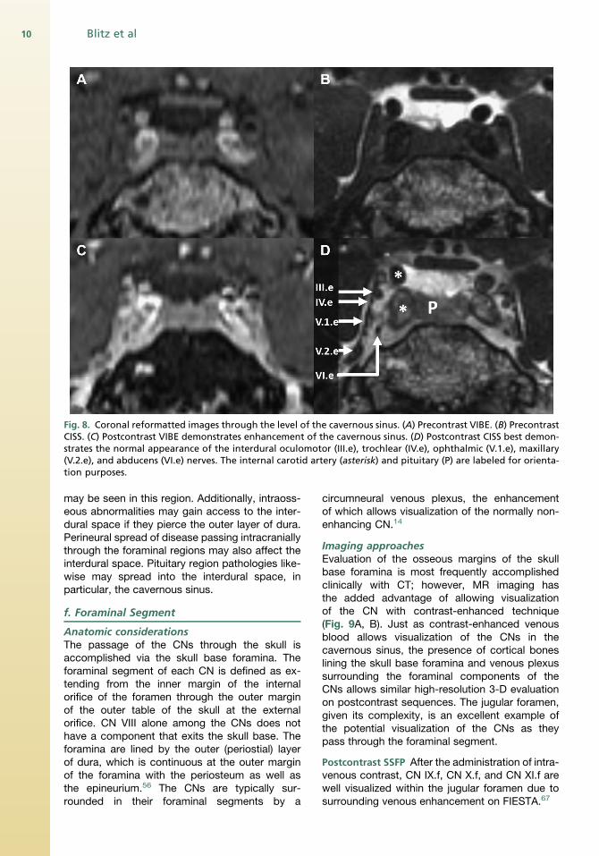
Fig. 8. Coronal reformatted images through the level of the cavernous sinus. (A) Precontrast VIBE. (B) PrecontrastCISS. (C) Postcontrast VIBE demonstrates enhancement of the cavernous sinus. (D) Postcontrast CISS best demon-strates the normal appearance of the interdural oculomotor (III.e), trochlear (IV.e), ophthalmic (V.1.e), maxillary(V.2.e), and abducens (VI.e) nerves. The internal carotid artery (asterisk) and pituitary (P) are labeled for orienta-tion purposes.
Blitz et al10
may be seen in this region. Additionally, intraoss-eous abnormalities may gain access to the inter-dural space if they pierce the outer layer of dura.Perineural spread of disease passing intracraniallythrough the foraminal regions may also affect theinterdural space. Pituitary region pathologies like-wise may spread into the interdural space, inparticular, the cavernous sinus.
f. Foraminal Segment
Anatomic considerationsThe passage of the CNs through the skull isaccomplished via the skull base foramina. Theforaminal segment of each CN is defined as ex-tending from the inner margin of the internalorifice of the foramen through the outer marginof the outer table of the skull at the externalorifice. CN VIII alone among the CNs does nothave a component that exits the skull base. Theforamina are lined by the outer (periostial) layerof dura, which is continuous at the outer marginof the foramina with the periosteum as well asthe epineurium.56 The CNs are typically sur-rounded in their foraminal segments by a
circumneural venous plexus, the enhancementof which allows visualization of the normally non-enhancing CN.14
Imaging approachesEvaluation of the osseous margins of the skullbase foramina is most frequently accomplishedclinically with CT; however, MR imaging hasthe added advantage of allowing visualizationof the CN with contrast-enhanced technique(Fig. 9A, B). Just as contrast-enhanced venousblood allows visualization of the CNs in thecavernous sinus, the presence of cortical boneslining the skull base foramina and venous plexussurrounding the foraminal components of theCNs allows similar high-resolution 3-D evaluationon postcontrast sequences. The jugular foramen,given its complexity, is an excellent example ofthe potential visualization of the CNs as theypass through the foraminal segment.
Postcontrast SSFP After the administration of intra-venous contrast, CN IX.f, CN X.f, and CN XI.f arewell visualized within the jugular foramen due tosurrounding venous enhancement on FIESTA.67

Fig. 9. (A) Precontrast CISS in a patient without osseous pathology of the skull base. Multiplanar reformatperpendicular to the hypoglossal canal demonstrating the cortical margin (arrow). (B) Postcontrast CISS demon-strates CN XII.f (arrow) surrounded by enhancement of the venous plexus. The cortical margin of the foramen isintact. (C) On the contralateral side, a component of a large chordoma (asterisk) involving the posterior skull baseinterrupts the cortical margin of the foramen and minimally extends into the hypoglossal canal to abut CN XII.f(arrow).
Magnetic Resonance Imaging 11
Contrast-enhanced magnetic resonance
angiograph Linn and colleagues68 have describedthe use of CE-MRA in the jugular foramen and re-ported overall improved visualization of the CNscompared with contrast-enhanced FIESTA al-though some structures were better visualizedwith contrast-enhanced FIESTA. The investigatorswere careful to match time of acquisition; how-ever, CE-MRA was performed before contrast-enhanced FIESTA. It is not clear to what extentthe greater than 7-minute delay for performanceof CE-MRA may have had on comparison withthe subsequently performed FIESTA. The investi-gators suggest performance of CE-MRA if pathol-ogy of the foramen itself is suspected and FIESTAimaging for cases when lower CN pathology issuspected but the timing is less clear.
Selected pathologic entitiesWhen encountered in isolation, pathologic condi-tions of the foraminal segment of the CNs aremost commonly the result of extension of an ab-normality from within the adjacent bone (eg, seeFig. 9C).
g. Extraforaminal Segment
Anatomic considerationsThe extraforaminal segment (g) begins at the planethat passes through the outer cortex of the outermargin of the appropriate foramen. The proximalextraforaminal segment typically passes at leastinitially through fat before coming into contactwith the vascular structures, glands, and musclesof the head and neck. Among the CNs, CN X.ghas the most extensive extraforaminal course(implied by the name of CN X, vagus [wanderer])and reaches as far as the abdomen.
Imaging approachesCISS with and without contrast Both fat and fluidreturn high signal on balanced SSFP sequences,such as CISS, due to their high T2/T1 ratios.43
The environment of the extraforaminal CNs con-sists of fat, muscle, bone, and vascular structures,which can be readily distinguished on CISS.Despite the course of multiple extraforaminal com-ponents of the CNs near the air-containing para-nasal sinuses and aerodigestive tract, perhapsbecause of the reduced T2* sensitivity of balancedSSFP sequences43 as well as the small voxelsused, resultant artifacts tend not to significantlylimit such evaluations. The use of CISS imagingin the extraforaminal regions of the suprahyoidneck allows exquisite anatomic definition of struc-tures that have not been typically well visualizedwith prior techniques (Fig. 10) and has been exten-sively used at the authors’ institution for thispurpose. The addition of intravenous contrastheightens the distinction between the extraforami-nal CNs and adjacent structures. In conjunctionwith 3-D T1 and short tau inversion recovery(STIR) sequences, comparison of precontrastand postcontrast CISS imaging allows evaluationof small regions of pathologic enhancement,such asmight be encountered in perineural spreadof neoplasm or in highlighting the relationship ofthe CN to an enhancing mass (see Fig. 10C).
Reverse FISP/Neurography 3-D PSIF with diffusionweighting has been reported by Zhang and col-leagues69 as demonstrating the course of theCNs. The investigators evaluated the results ofan approximately 10-minute PSIF acquisitionwith a diffusion moment of 20 mT/m*ms andconcluded the technique “cannot be used as a
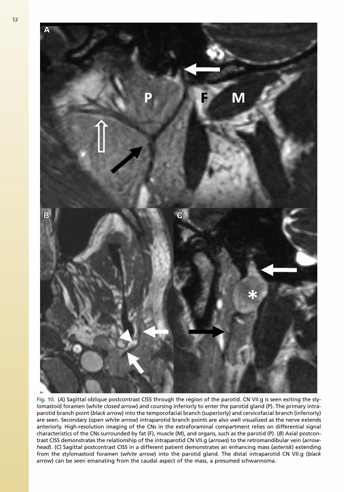
Fig. 10. (A) Sagittal oblique postcontrast CISS through the region of the parotid. CN VII.g is seen exiting the sty-lomastoid foramen (white closed arrow) and coursing inferiorly to enter the parotid gland (P). The primary intra-parotid branch point (black arrow) into the temporofacial branch (superiorly) and cervicofacial branch (inferiorly)are seen. Secondary (open white arrow) intraparotid branch points are also well visualized as the nerve extendsanteriorly. High-resolution imaging of the CNs in the extraforaminal compartment relies on differential signalcharacteristics of the CNs surrounded by fat (F), muscle (M), and organs, such as the parotid (P). (B) Axial postcon-trast CISS demonstrates the relationship of the intraparotid CN VII.g (arrows) to the retromandibular vein (arrow-head). (C) Sagittal postcontrast CISS in a different patient demonstrates an enhancing mass (asterisk) extendingfrom the stylomastoid foramen (white arrow) into the parotid gland. The distal intraparotid CN VII.g (blackarrow) can be seen emanating from the caudal aspect of the mass, a presumed schwannoma.
12

Magnetic Resonance Imaging 13
substitute for other standard sequences such as3D-CISS sequence or the 3-D fast spin echo(FSE) sequence” but may be most useful for eval-uation of CNs outside of the cranial compartment.This technique may be most useful in regions,such as the carotid sheath, where visualization ofthe CNs is inconstant.
Diffusion tensor imaging DTI using fat saturationat 3T with tractography has been reported by Akterand colleagues70 for imaging of the CNs within thehead and neck; they describe at least partial corre-lation between DTI and operative findings in 4 ofthe 5 patients studied.
SUMMARY
Imaging of the CNs presents a challenge due totheir small size and course. This article proposesa segmental classification system for radiologicevaluation of the CNs, which the authors hopeproves useful in clinical practice while providinga framework for future high-resolution CN imagingresearch. MR imaging is currently the gold stan-dard technique and a variety of pulse sequencesare available to demonstrate the CNs. The optimalimaging approach depends largely on whichsequence is best suited to demonstrating the CNin the segment of interest. Within the nuclear andfascicular segments, the CNs are often difficult todistinguish from surrounding brain parenchyma.Cisternal and dural cave segments are best visual-ized on T2-weighted sequences and SSFP se-quences. The interdural segments are best seenwith techniques that allow enhancement of thesurrounding venous blood, such as contrast-enhanced MRA or contrast-enhanced SSFPsequences; a similar approach is helpful for visual-ization within the skull base foramina. Within theextraforaminal segment, the CNs adjoin vascularstructures, fat, muscle, and/or bone as they passthrough the head and neck and may be visualizedwith a variety of techniques with SSFP sequences,such as CISS and PSIF, providing excellentanatomic detail. DTI has also been used for visual-ization of the CNs in the fascicular, cisternal, andextraforaminal segments.
The heterogeneity of anatomic context presentssignificant challenges for images. Given advan-tages and pitfalls of various imaging pulse se-quences, a fully refocused SSFP technique, suchas CISS, allows visualization of much of theCN course when precontrast and postcontrasttechniques are used. The accompanying articleby Blitz and colleagues elsewhere in this issue de-scribes the relevant anatomy and imaging appear-ance of the upper CNs on high-resolution CISS
imaging, using the segmental approach advo-cated in this article.
REFERENCES
1. Brazis PW, Masdeu JC, Biller J. Localization in Clin-
ical Neurology. Philadelphia: Lippincott Williams &
Wilkins; 2011.
2. DiChiroG.AnAtlasofDetailedNormalPneumoence-
phalographic Anatomy, 2e. Springfield: Charles C.
Thomas Publisher; 1971.
3. de Slegte R, Valk J, Lohman A, et al. Cisterno-
graphic Anatomy of the Poster Cranial Fossa:
High Resolution CT and MRI Study. Wolfeboro:
Vam Gorcum; 1986.
4. Fischbach F, Muller M, Bruhn H. Magnetic reso-
nance imaging of the cranial nerves in the posterior
fossa: a comparative study of t2-weighted spin-
echo sequences at 1.5 and 3.0 tesla. Acta Radiol
2008;49(3):358–63.
5. Penn R, Abemayor E, Nabili V, et al. Perineural
invasion detected by high-field 3.0-T magnetic
resonance imaging. Am J Otolaryngol 2010;31(6):
482–4.
6. Hart H, Bottomley P, Edelstein W, et al. Nuclear
magnetic resonance imaging: contrast-to-noise ra-
tio as a function of strength of magnetic field. Am J
Roentgenol 1983;141(6):1195–201.
7. Casselman J, Mermuys K, Delanote J, et al. MRI of
the cranial nerves—more than meets the eye: tech-
nical considerations and advanced anatomy. Neu-
roimaging Clin N Am 2008;18(2):197–231.
8. Fischbach F, Muller M, Bruhn H. High-resolution
depiction of the cranial nerves in the posterior
fossa (N III–N XII) with 2D fast spin echo and 3D
gradient echo sequences at 3.0 T. Clin Imaging
2009;33(3):169–74.
9. Choi B, Kim J, Jung C, et al. High-resolution 3D MR
imaging of the trochlear nerve. AJNR Am J Neuro-
radiol 2010;31(6):1076–9.
10. Leblanc A. The Cranial Nerves: Anatomy, Imaging,
Vascularisation. New York: Springer-Verlag; 1995.
11. Held P, Nitz W, Seitz J, et al. Comparison of 2D and
3D MRI of the optic and oculomotor nerve anatomy.
Clin Imaging 2000;24(6):337–43.
12. Hatipo�glu HG, Durako�glugil T, Ciliz D, et al. Com-
parison of FSE T2W and 3D FIESTA sequences in
the evaluation of posterior fossa cranial nerves
with MR cisternography. Diagn Interv Radiol
2007;13(2):56–60.
13. Iwayama E, Naganawa S, Ito T, et al. High-resolu-
tion MR cisternography of the cerebellopontine
angle: 2D versus 3D fast spin-echo sequences.
AJNR Am J Neuroradiol 1999;20(5):889–95.
14. Williams LS, Schmalfuss IM, Sistrom CL, et al. MR
imaging of the trigeminal ganglion, nerve, and the
perineural vascular plexus: normal appearance

Blitz et al14
and variants with correlation to cadaver specimens.
AJNR Am J Neuroradiol 2003;24(7):1317–23.
15. Gebarski S, Telian S, Niparko J. Enhancement
along the normal facial nerve in the facial canal:
MR imaging and anatomic correlation. Radiology
1992;183(2):391–4.
16. Saremi F, Helmy M, Farzin S, et al. MRI of cranial
nerve enhancement. Am J Roentgenol 2005;
185(6):1487–97.
17. Whitmore I. Terminologia Anatomica: International
Anatomical terminology; FIPAT, Federative interna-
tional Programme on Anatomical Terminologies.
New York: Thieme; 2011.
18. Nieuwenhuys R, Voogd J, Voogd J, et al. The Hu-
man Central Nervous System, 4e. Springer Verlag;
2008.
19. Wilson-Pauwels L, Akesson EJ, Stewart PA. Cranial
Nerves. Hamilton, Canada: Decker; 1988.
20. Nolte J. The Human Brain: An Introduction to its
Functional Anatomy, 5e. St. Louis: Mosby; 2002.
21. Barkovich AJ. MR of the normal neonatal brain:
assessment of deep structures. AJNR Am J Neuro-
radiol 1998;19(8):1397–403.
22. Nagae-Poetscher LM, Jiang H, Wakana S, et al.
High-resolution diffusion tensor imaging of the
brain stem at 3 T. AJNR Am J Neuroradiol 2004;
25(8):1325–30.
23. Tomii M, Onoue H, Yasue M, et al. Microscopic
measurement of the facial nerve root exit zone
from central glial myelin to peripheral Schwann
cell myelin. J Neurosurg 2003;99(1):121–4.
24. Campos-Benitez M, Kaufmann AM. Neurovascular
compression findings in hemifacial spasm.
J Neurosurg 2008;109(3):416–20.
25. Fraher J, Smiddy P, O’Sullivan V. The central-
peripheral transitional regions of cranial nerves.
Oculomotor nerve. J Anat 1988;161:103–13.
26. Naidich TP, Duvernoy HM, Delman BN, et al. Du-
vernoy’s Atlas of the Human Brain Stem and Cere-
bellum. Vienna (Austria): Springer-Verlag; 2009.
27. Hodaie M, Quan J, Chen DQ. In vivo visualization of
cranial nerve pathways in humans using diffusion-
based tractography. Neurosurgery 2010;66(4):
788–96.
28. Yamada K, Shiga K, Kizu O, et al. Oculomotor
nerve palsy evaluated by diffusion-tensor tractog-
raphy. Neuroradiology 2006;48(6):434–7.
29. Adachi M, Kabasawa H, Kawaguchi E. Depiction of
the cranial nerves within the brain stem with use of
PROPELLER multishot diffusion-weighted imaging.
AJNR Am J Neuroradiol 2008;29(5):911–2.
30. Nathan H, Ouaknine G, Kosary IZ. The abducens
nerve. J Neurosurg 1974;41(5):561–6.
31. Fraher J, Smiddy P, O’Sullivan V. The central-
peripheral transitional regions of cranial nerves.
Trochlear and abducent nerves. J Anat 1988;161:
115–23.
32. Lang J. Clinical Anatomy of the Head. Berlin:
Springer-Verlag; 1983.
33. Marinkovic SV, Gibo H, Stimec B. The neurovascu-
lar relationships and the blood supply of the abdu-
cent nerve: surgical anatomy of its cisternal
segment. Neurosurgery 1994;34(6):1017–26.
34. Obersteiner H, Redlich E. Ueber Wesen Und Path-
ogenese Der Tabischen Hinterstrangsdegenera-
tion. Arb Neurol Inst Univ Wien 1894;1(3):152–72.
35. Yousry I, Camelio S, Schmid U, et al. Visualization
of cranial nerves I–XII: value of 3D CISS and
T2-weighted FSE sequences. Eur Radiol 2000;
10(7):1061–7.
36. Mamata Y, Muro I, Matsumae M, et al. Magnetic
resonance cisternography for visualization of intra-
cisternal fine structures. J Neurosurg 1998;88(4):
670–8.
37. Ciftci E, Anik Y, Arslan A, et al. Driven equilibrium
(drive) MR imaging of the cranial nerves V–VIII:
comparison with the T2-weighted 3D TSE
sequence. Eur J Radiol 2004;51(3):234–40.
38. Naganawa S, Koshikawa T, Fukatsu H, et al. MR
cisternography of the cerebellopontine angle: com-
parison of three-dimensional fast asymmetrical
spin-echo and three-dimensional constructive in-
terference in the steady-state sequences. AJNR
Am J Neuroradiol 2001;22(6):1179–85.
39. Sheth S, Branstetter BF IV, Escott EJ. Appearance
of normal cranial nerves on steady-state free pre-
cession MR images1. Radiographics 2009;29(4):
1045–55.
40. Casselman J, Kuhweide R, Deimling M, et al.
Constructive interference in steady state-3DFT
MR imaging of the inner ear and cerebellopontine
angle. AJNR Am J Neuroradiol 1993;14(1):47–57.
41. Seitz J, Held P, FrundR, et al. Visualization of the IXth
toXIIth cranial nervesusing3-dimensional construc-
tive interference in steady state, 3-dimensional
magnetization-prepared rapid gradient echo and
T2-weighted 2-dimensional turbo spin echo mag-
netic resonance imaging sequences. J Neuroimag-
ing 2001;11(2):160–4.
42. Yoshino N, Akimoto H, Yamada I, et al. Trigeminal
neuralgia: evaluation of neuralgic manifestation
and site of neurovascular compression with 3D
CISS MR imaging and MR angiography1. Radi-
ology 2003;228(2):539–45.
43. Chavhan GB, Babyn PS, Jankharia BG, et al.
Steady-state MR imaging sequences: physics,
classification, and clinical applications. Radio-
graphics 2008;28(4):1147–60.
44. Shigematsu Y, Korogi Y, Hirai T, et al. Contrast-
enhanced CISS MRI of vestibular schwannomas:
phantom and clinical studies. J Comput Assist
Tomogr 1999;23(2):224–31.
45. Taoka T, Hirabayashi H, Nakagawa H, et al.
Displacement of the facial nerve course by

Magnetic Resonance Imaging 15
vestibular schwannoma: preoperative visualization
using diffusion tensor tractography. J Magn Reson
Imaging 2006;24(5):1005–10.
46. Chen DQ, Quan J, Guha A, et al. Three-dimensional
in vivo modeling of vestibular schwannomas and
surrounding cranial nerves with diffusion imaging
tractography. Neurosurgery 2011;68(4):1077–83.
47. Lutz J, Linn J, Mehrkens JH, et al. Trigeminal neu-
ralgia due to neurovascular compression: high-
spatial-resolution diffusion-tensor imaging reveals
microstructural neural changes. Radiology 2011;
258(2):524–30.
48. Fraher JP. The transitional zone and CNS regener-
ation. J Anat 1999;194(2):161–82.
49. Xenellis JE, Linthicum FH Jr. On the myth of the
glial/schwann junction (Obersteiner-Redlich zone):
origin of vestibular nerve schwannomas. Otol Neu-
rotol 2003;24(1):1.
50. Jannetta PJ. Arterial compression of the trigeminal
nerve at the pons in patients with trigeminal neural-
gia. J Neurosurg 1967;26(Suppl 1):159–62.
51. Guclu B, Sindou M, Meyronet D, et al. Cranial nerve
vascular compression syndromes of the trigeminal,
facial and vago-glossopharyngeal nerves: compar-
ative anatomical study of the central myelin portion
and transitional zone; correlations with incidences
of corresponding hyperactive dysfunctional syn-
dromes. Acta Neurochir 2011;153(12):2365–75.
52. Kakizawa Y, Seguchi T, Kodama K, et al. Anatom-
ical study of the trigeminal and facial cranial nerves
with the aid of 3.0-tesla magnetic resonance imag-
ing. J Neurosurg 2008;108(3):483–90.
53. Benes L, Shiratori K, Gurschi M, et al. Is preopera-
tive high-resolution magnetic resonance imaging
accurate in predicting neurovascular compression
in patients with trigeminal neuralgia? Neurosurg
Rev 2005;28(2):131–6.
54. Joo W, Yoshioka F, Funaki T, et al. Microsurgical
anatomy of the abducens nerve. Clin Anat 2012;
25(8):1030–42.
55. McCabe JS, Low FN. The subarachnoid angle: an
area of transition in peripheral nerve. Anat Rec
1969;164(1):15–33.
56. Janjua RM, Al-Mefty O, Densler DW, et al. Dural rela-
tionships of Meckel cave and lateral wall of the
cavernous sinus.NeurosurgFocus2008;25(6):1–12.
57. Kaufman B, Bellon EM. The trigeminal nerve
cistern. Radiology 1973;108(3):597–602.
58. Ono K, Arai H, Endo T, et al. Detailed MR imaging
anatomy of the abducent nerve: evagination of CSF
into Dorello canal. AJNR Am J Neuroradiol 2004;
25(4):623–6.
59. Everton K, Rassner U, Osborn A, et al. The oculo-
motor cistern: anatomy and high-resolution imag-
ing. AJNR Am J Neuroradiol 2008;29(7):1344–8.
60. Yousry I, Camelio S, Wiesmann M, et al. Detailed
magnetic resonance imaging anatomy of the
cisternal segment of the abducent nerve: Dorello’s
canal and neurovascular relationships and land-
marks. J Neurosurg 1999;91(2):276–83.
61. Yousry I, Moriggl B, Schmid UD, et al. Trigeminal
ganglion and its divisions: detailed anatomic MR
imaging with contrast-enhanced 3D constructive
interference in the steady state sequences. AJNR
Am J Neuroradiol 2005;26(5):1128–35.
62. Yasuda A, Campero A, Martins C, et al. The medial
wall of the cavernous sinus: microsurgical anatomy.
Neurosurgery 2004;55(1):179–90.
63. Parkinson D. Extradural neural axis compartment.
J Neurosurg 2000;92(4):585–8.
64. Umansky F, Valarezo A, Elidan J. The micro-
surgical anatomy of the abducens nerve in its
intracranial course. Laryngoscope 1992;102(11):
1285–92.
65. Yagi A, Sato N, Taketomi A, et al. Normal cranial
nerves in the cavernous sinuses: contrast-
enhanced three-dimensional constructive interfer-
ence in the steady state MR imaging. AJNR Am J
Neuroradiol 2005;26(4):946–50.
66. Linn J, Peters F, Lummel N, et al. Detailed imaging
of the normal anatomy and pathologic conditions of
the cavernous region at 3 Tesla using a contrast-
enhanced MR angiography. Neuroradiology 2011;
53(12):947–54.
67. Davagnanam I, Chavda S. Identification of the
normal jugular foramen and lower cranial nerve
anatomy: contrast-enhanced 3D fast imaging em-
ploying steady-state acquisition MR imaging.
AJNR Am J Neuroradiol 2008;29(3):574–6.
68. Linn J, Peters F, Moriggl B, et al. The jugular fora-
men: imaging strategy and detailed anatomy at
3T. AJNR Am J Neuroradiol 2009;30(1):34–41.
69. Zhang Z, Meng Q, Chen Y, et al. 3-T imaging of the
cranial nerves using three-dimensional reversed
FISP with diffusion-weighted MR sequence.
J Magn Reson Imaging 2008;27(3):454–8.
70. Akter M, Hirai T, Minoda R, et al. Diffusion tensor
tractography in the head-and-neck region using a
clinical 3-T MR scanner. Acad Radiol 2009;16(7):
858–65.