Anastasia Herk IBACOS, Inc. - NREL · viii List of Tables Table 1. Specifications for the...
65
Mini-Split Heat Pump Evaluation and Zero Energy Ready Home Support Anastasia Herk IBACOS, Inc. January 2017
Transcript of Anastasia Herk IBACOS, Inc. - NREL · viii List of Tables Table 1. Specifications for the...
Mini-Split Heat Pump Evaluation and Zero Energy Ready Home Support Anastasia Herk IBACOS, Inc.
January 2017

iii
NOTICE
This report was prepared as an account of work sponsored by an agency of the United States government. Neither the United States government nor any agency thereof, nor any of their employees, subcontractors, or affiliated partners makes any warranty, express or implied, or assumes any legal liability or responsibility for the accuracy, completeness, or usefulness of any information, apparatus, product, or process disclosed, or represents that its use would not infringe privately owned rights. Reference herein to any specific commercial product, process, or service by trade name, trademark, manufacturer, or otherwise does not necessarily constitute or imply its endorsement, recommendation, or favoring by the United States government or any agency thereof. The views and opinions of authors expressed herein do not necessarily state or reflect those of the United States government or any agency thereof.
This report is available at no cost from the National Renewable Energy Laboratory (NREL) at www.nrel.gov/publications.
Available electronically at SciTech Connect http:/www.osti.gov/scitech
Available for a processing fee to U.S. Department of Energy and its contractors, in paper, from:
U.S. Department of Energy Office of Scientific and Technical Information P.O. Box 62 Oak Ridge, TN 37831-0062 OSTI http://www.osti.gov Phone: 865.576.8401 Fax: 865.576.5728 Email: [email protected]
Available for sale to the public, in paper, from: U.S. Department of Commerce National Technical Information Service 5301 Shawnee Road Alexandria, VA 22312 NTIS http://www.ntis.gov Phone: 800.553.6847 or 703.605.6000 Fax: 703.605.6900 Email: [email protected]
iii
Mini-Split Heat Pump Evaluation and Zero Energy Ready Home Support
Prepared for:
The National Renewable Energy Laboratory
On behalf of the U.S. Department of Energy’s Building America Program
Office of Energy Efficiency and Renewable Energy
15013 Denver West Parkway
Golden, CO 80401
NREL Contract No. DE-AC36-08GO28308
Prepared by:
Anastasia Herk
IBACOS, Inc.
2214 Liberty Avenue
Pittsburgh, PA 15222
NREL Technical Monitor: Stacey Rothgeb
Prepared under Subcontract No. KNDJ-0-40641-05
January 2017

iv
The work presented in this report does not represent performance of any product relative to regulated minimum efficiency requirements.
The laboratory and/or field sites used for this work are not certified rating test facilities. The conditions and methods under which products were characterized for this work differ from standard rating conditions, as described.
Because the methods and conditions differ, the reported results are not comparable to rated product performance and should only be used to estimate performance under the measured conditions.

v
Acknowledgments
The author acknowledges John Friesenhahn and his team at Imagine Homes for their contributions to this research.

vi
Contents Acknowledgments ...................................................................................................................................... v List of Figures ........................................................................................................................................... vii List of Tables ............................................................................................................................................ viii Definitions ................................................................................................................................................... ix Executive Summary ................................................................................................................................... xi 1 Introduction ........................................................................................................................................... 1
1.1 Background ..........................................................................................................................1 1.2 Overview of the Builder.......................................................................................................2
1.2.1 Builder’s Standard versus Test House Specification ...............................................3 1.2.2 Test House Location ................................................................................................5 1.2.3 Test House Model ....................................................................................................6
2 Technical Challenges ........................................................................................................................... 8 2.1 Mini-Split Heat Pump System .............................................................................................8 2.2 Zero Energy Ready Home Program Compliance ................................................................8 2.3 Research Questions ..............................................................................................................9
3 Mathematical and Modeling Methods ............................................................................................... 10 3.1 Building Energy Optimization Software ...........................................................................10 3.2 THERM..............................................................................................................................13 3.3 Air Conditioning Contractors of America Manuals J, S, and D ........................................15 3.4 REM/Rate ..........................................................................................................................15
4 Research and Experimental Methods .............................................................................................. 17 4.1 Zero Energy Ready Home Technical Approach ................................................................17 4.2 Mini-Split Heat Pump Technical Approach ......................................................................18 4.3 Short-Term Test Methods ..................................................................................................18
4.3.1 Room-by-Room Supply Register Airflow (Ducted Units) ....................................18 4.3.2 Total Supply Airflow (Ductless Units) ..................................................................19 4.3.3 Duct Air Leakage ...................................................................................................19 4.3.4 Whole-Building Air Leakage .................................................................................19 4.3.5 Room Pressures ......................................................................................................19 4.3.6 Energy Recovery Ventilator Airflow Balancing ....................................................20 4.3.7 Equipment ..............................................................................................................20
4.4 Long-Term Monitoring and Data Collection .....................................................................20 5 Results ................................................................................................................................................. 25
5.1 Short-Term Test Results ....................................................................................................25 5.1.1 Room-by-Room Supply Register Airflows (Ducted Units)...................................25 5.1.2 Total Supply Airflows (Ductless Units) ................................................................25 5.1.3 Duct Air Leakage ...................................................................................................26 5.1.4 Whole-House Air Leakage ....................................................................................26 5.1.5 Room Pressures ......................................................................................................26 5.1.6 Energy Recovery Ventilator Airflow Balancing ....................................................27 5.1.7 Long-Term Monitoring and Data Collection at the Test House ............................27
5.2 Test House Costing ............................................................................................................35 5.3 Zero Energy Ready Home Costing ....................................................................................37
6 Discussion ........................................................................................................................................... 38 6.1 Mini-Split Heat Pump Performance...................................................................................38 6.2 Mini-Split Heat Pump Constructability, Marketability, and Cost .....................................39
vii
6.3 Zero Energy Ready Home Design Integration ...................................................................42 7 Conclusions ........................................................................................................................................ 44 References ................................................................................................................................................. 46 Appendix A: HVAC System Design ......................................................................................................... 48 Appendix B: Monitoring System Design Diagram ................................................................................. 50
List of Figures Figure 1. Location of the test house community (The Reserve at Old Fredericksburg) ..................... 5 Figure 2. Lot location of the test house .................................................................................................... 5 Figure 3. First-floor plan of the test house ............................................................................................... 6 Figure 4. Second-floor plan of the test house.......................................................................................... 6 Figure 5. Front elevation of the test house .............................................................................................. 7 Figure 6. BEopt optimization of the thermal enclosure and mechanical system, showing the test
house (PT1) and the BAB .................................................................................................................. 11 Figure 7. BEopt optimization of Model 2247, showing specifications for the BAB, the builder’s
standard (PT1), a likely ZERH (PT2), and the 2013 test house (PT3) ............................................ 12 Figure 8. BEopt optimization of Model 3247, showing specifications for the BAB, the builder’s
standard (PT1), a likely ZERH (PT2), and the 2013 test house (PT3) ............................................ 12 Figure 9. BEopt optimization of Model 3908, showing specifications for the BAB, the builder’s
standard (PT1), a likely ZERH (PT2), and the 2013 test house (PT3) ............................................ 13 Figure 10. Winter performance of the slab insulation strategy. Design temperatures are 27°F
outdoors and 70°F indoors. ............................................................................................................... 14 Figure 11. Summer performance of the slab insulation strategy. Outdoor design temperatures
are 99°F outdoors and 70°F indoors. ................................................................................................ 15 Figure 12. Data logging control center in the garage ............................................................................ 23 Figure 13. Wireless temperature and RH sensor at the thermostat .................................................... 24 Figure 14. Room temperature and RH sensor........................................................................................ 24 Figure 15. Temperature and RH of rooms and power draw for MSHP units associated with
Outdoor Unit 1 in cooling mode ........................................................................................................ 28 Figure 16. Temperature and RH of rooms and power draw for MSHP units associated with
Outdoor Unit 2 in cooling mode ........................................................................................................ 29 Figure 17. Fireplace and MSHP operation and associated living area temperatures during the
heating season.................................................................................................................................... 30 Figure 18. Temperature differences and runtime profiles for primary living space in
cooling mode ...................................................................................................................................... 31 Figure 19. Temperature and system operation profiles for bedroom spaces during the cooling
season ................................................................................................................................................. 32 Figure 20. Bedroom temperature deviations during the heating season ........................................... 33 Figure 21. Living space stratification on a hot sunny day with typical system operation ................ 34 Figure 22. Living space stratification on a shoulder day with no system runtime ............................ 35 Figure 23. Space-conditioning system diagram, first floor .................................................................. 48 Figure 24. Space-conditioning system diagram, second floor ............................................................ 48 Figure 25. Ventilation system diagram, first floor ................................................................................. 49 Figure 26. Ventilation system diagram, second floor ........................................................................... 49 Figure 27. Monitoring system diagram, first floor ................................................................................. 50 Figure 28. Monitoring system diagram, second floor ........................................................................... 51 Figure 29. Monitoring system diagram, elevation ................................................................................. 52
Unless otherwise noted, all figures and photos were created by IBACOS.
viii
List of Tables Table 1. Specifications for the Builder’s Standard Package, the Test House Package, and a
Likely ZERH Package ........................................................................................................................... 4 Table 2. Projected HERS Index of Builder's Standard Package and Verified HERS Index of
Test House, with and without PV ...................................................................................................... 15 Table 3. Projected HERS Index and Building America Source Energy Savings ................................ 16 Table 4. Equipment Used for Short-Term Performance Tests ............................................................. 20 Table 5. Long-Term Monitoring Equipment Installed in the Test House ............................................. 22 Table 6. Room-by-Room Supply Register Airflow (Ducted Units) ....................................................... 25 Table 7. Design versus Measured Supply Airflows (Ductless Units) .................................................. 26 Table 8. Duct Air Leakage ........................................................................................................................ 26 Table 9. Whole-House Air Leakage ......................................................................................................... 26 Table 10. Room Pressures ....................................................................................................................... 27 Table 11. ERV Balanced Velocities and Airflows ................................................................................... 27 Table 12. HVAC Usage Patterns by Zone ............................................................................................... 28 Table 13. Costs of Standard and Test House Specifications ............................................................... 36 Table 14. Zero Energy Ready Home Specification Costing .................................................................. 37
Unless otherwise noted, all tables were created by IBACOS.

ix
Definitions
ACCA Air Conditioning Contractors of America
AFUE annual fuel utilization efficiency
AHU air handling unit
BAB Building America Benchmark
BEopt™ Building Energy Optimization (software)
CFL compact fluorescent lamp
cfm cubic feet per minute
DOE U.S. Department of Energy
EF energy factor
ERV energy recovery ventilator
HERS Index Home Energy Rating System Index
HSP House Simulation Protocols
HSPF heating seasonal performance factor
HVAC heating, ventilating, and air conditioning
kBtu/h thousand British thermal units per hour
LED light-emitting diode
MBtu/yr million British thermal units per year
MSHP mini-split heat pump
Pa Pascal
PEX cross-linked polyethylene
PV photovoltaic
RH relative humidity
SEER seasonal energy efficiency ratio

x
SHGC solar heat gain coefficient
XPS extruded polystyrene
ZERH Zero Energy Ready Home
xi
Executive Summary
This project was created from a partnership between the U.S. Department of Energy’s (DOE’s) Building America research team, IBACOS, Inc., and a production builder of high-performance homes called Imagine Homes, which is located in San Antonio, Texas—a hot-humid climate. The primary purpose of this project was to evaluate the performance of a multihead mini-split heat pump (MSHP) space-conditioning system in maintaining uniform comfort in an occupied test house. The MSHP consists of ducted and ductless indoor units.
The research team evaluated this MSHP space-conditioning strategy for its effectiveness in achieving uniform temperature and relative humidity (RH) levels throughout the test house and for overall constructability and cost. This evaluation was based on data that were collected from short-term tests and monitoring of the house during 1 year of occupancy and from builder and occupant feedback. Design considerations for integrating an MSHP system into the builder’s full range of production home designs were also explored; the focus was on minimizing the cost and complexity of the system design while meeting the thermal loads of the house and providing occupant comfort according to ANSI/ASHRAE Standard 55-2010 (ASHRAE 2010a).
To reduce overall cost and to improve attic insulation R-values, the test house also incorporated a vented attic assembly with blown cellulose on the flat ceiling instead of the builder’s standard cathedralized attic assembly with spray foam insulating (and air sealing) the roof deck and gable walls.
IBACOS also worked with the builder to evaluate the design and specification changes that are necessary to comply with DOE Zero Energy Ready Home (ZERH) requirements on 100% of its current production line (DOE 2014). This evaluation was intended to support the builder in deciding whether to move forward with the ZERH program and to provide DOE with useful feedback about the attractiveness and challenges of the program to a production builder.
Based on the results of short-term testing and long-term monitoring of the home’s performance, the research team determined that the MSHP system maintained adequate occupant comfort. As well, the homeowners reported they were “extremely satisfied” with the comfort provided by the system in their home.
Despite the homeowners’ self-reported satisfaction, measured comfort conditions in the home varied in some interesting ways. Temperatures and RH levels were not uniform throughout the home and over time. Temperatures often varied well beyond ±2°F from the thermostat reading. The RH levels also varied significantly—in some instances by as much as 20%. The occupants operated the indoor air handling units (AHUs) intermittently and variably; they even left some AHUs inactive during much of the test period. The occupants also opened windows when outdoor conditions were favorable and operated their gas fireplace as a supplemental space-conditioning system. It is not generally clear how much of the temperature and RH variations resulted from the performance of the MSHP system and how much were a result of the occupants’ chosen behaviors.
The builder was interested in the efficiency and effectiveness stories of the MSHP system and vented attic assembly, and the stories resonated with some potential homebuyers. The system’s

xii
selling points included quiet operation and the elimination of “dirty” duct systems. However, most buyers preferred the builder’s standard, unvented cathedralized attic assembly and were not happy with the aesthetics of the ductless AHUs. Also, the initial cost of this MSHP system was significantly higher than that of the builder’s standard space-conditioning system, and the ducted MSHP units are actually less efficient than the builder’s standard system. For such reasons, the builder believes marketing of the MSHP and the vented attic will be challenging. The builder has decided to not move forward with this MSHP system as standard until the cost can be significantly reduced and the overall installed efficiency is significantly higher. The builder is similarly reluctant to deviate from the tried-and-true market acceptance it has experienced with the cathedralized attic.
One conclusion made from this project is that home designs can be improved to better embrace the MSHP technology by creating a more open floor plan and centrally locating bedrooms (which often are occupied with doors closed). Fewer overall indoor AHUs would thus be required, and more of the AHUs used would be the higher efficiency ductless units. Ideally, only one ducted unit would be used for the cluster of bedrooms. Although an ideal floor plan arrangement to support MSHPs can be challenging to execute in larger and more complex homes, builders would generally benefit from seeking opportunities to minimize or eliminate ducted AHUs and to use ductless AHUs.
Overall, the partner builder is committed to building high-performance homes and would like to move forward with constructing certified ZERHs as a standard offering at some point. However, until the “renewable ready” solar thermal requirement is eliminated from the ZERH requirements, it represents a “deal breaker” for the builder. With “version 2” of the ZERH program nearing release and eliminating the solar thermal requirement in homes with tankless water heaters installed, the builder is likely to revisit its decision not to move ahead with this program.
Many of the lessons learned from this project are relevant to the goals of the Building America program and to advancing the agenda of delivering high-performance homes to the market. With improved thermal enclosures and reduced thermal loads, the space-conditioning systems must adapt to provide sufficient comfort in heating, cooling, and part-load conditions and to appropriately treat latent loads in homes. Equally important is the need for installed space-conditioning systems to be flexible and adaptable to occupant behaviors and preferences. Windows may be opened and closed, and fireplaces could be operated—thereby introducing additional sensible and latent loads to the house. A point reinforced by this project is that an ideal space-conditioning system should provide a high level of individual space comfort control in a house. The system would meet the specific and varying needs of the occupants and would provide a greater sense of comfort because the occupants have been empowered with control.

1
1 Introduction
This project was created from a partnership between the U.S. Department of Energy’s (DOE’s) Building America research team IBACOS, Inc. and Imagine Homes, a production homebuilder of high-performance homes in San Antonio, Texas—a hot-humid climate. The primary purpose was to evaluate the performance of a multihead mini-split heat pump (MSHP) space-conditioning system, which consists of ducted and ductless indoor units, in maintaining uniform comfort in an occupied test house.
The research team evaluated the MSHP space-conditioning strategy for its effectiveness in achieving uniform temperature and relative humidity (RH) levels throughout the test house and for overall constructability and cost. This evaluation was based on data that were collected from short-term tests and monitoring during 1 year of occupancy, as well as from builder and occupant feedback. Design considerations for integrating an MSHP system into the builder’s full range of production home designs were also explored, with a focus on minimizing the cost and complexity of the system design while meeting the thermal loads of the house and providing occupant comfort according to ANSI/ASHRAE Standard 55-2010 (ASHRAE 2010a).
To reduce overall cost and to improve attic insulation R-values, the test house also incorporated a vented attic assembly with blown cellulose on the flat ceiling instead of the builder’s standard cathedralized attic assembly with spray foam insulating (and sealing) the roof deck and gable walls.
IBACOS worked with the builder to evaluate the design and specification changes that are necessary to comply with DOE Zero Energy Ready Home (ZERH) requirements on 100% of its current production line (DOE 2014). The evaluation was intended to support the builder in deciding to move forward with the ZERH program and to provide DOE with useful feedback about the attractiveness and challenges of the program to a production builder.
1.1 Background As building enclosures have become more robust and as heat transfer through the building enclosure has been reduced, space-conditioning loads have been influenced to a greater degree by internal gains and to a lesser degree by outside conditions. Conventional forced-air space-conditioning systems were designed to “wash” exterior walls with conditioned air to mitigate these outside loads. Modern space-conditioning systems now must adapt to the shifting load profiles to provide sufficient comfort and to operate as efficiently and effectively as possible.
Conventional space-conditioning equipment typically is manufactured in capacities of 18 kBtu/h or higher, which can be problematic in low-load homes. Equipment can easily be oversized, providing a poor match of capacity and load and resulting in poor temperature and humidity control. Also, the availability of ductwork that is smaller than 4 in. in diameter to accommodate the resulting lower airflow volumes may be limited because it is used infrequently.
The growing issue of “rightsizing” the capacity in accordance with the loads provides an emerging opportunity for the use of smaller and more compact space-conditioning strategies such as MSHP systems for delivering the needed heating and cooling to all zones of the house. MSHP equipment is available in lower nominal capacities (less than 1 ton or 12 kBtu/h) than
2
conventional split-system sizes (typically 1.5 to 5 tons or 18 kBtu/h to 60 kBtu/h) and can better meet the reduced loads of the high-performance homes and the smaller loads of individual zones within the home.
However, MSHP strategies can also be problematic because installing an indoor air handling unit (AHU) in each room or thermal zone can become significantly more expensive than installing a centrally ducted split system; thus, many builders are unwilling to invest in the higher-priced equipment. To reduce cost, fewer indoor AHUs could be installed, but whether conditioned air would be sufficiently circulated to provide comfort in all thermal zones—especially if a zone is isolated by a closed interior partition door—may be unclear. The goals of this current research into MSHP design strategies were to:
• Analyze the design implications of using an MSHP system.
• Provide uniform comfort throughout the house.
• Meet calculated building loads.
• Minimize the cost of the system by minimizing the number of installed indoor AHUs.
The energy conservation measure package that was designed for the test house was selected through ongoing discussions with the builder; the initial costs and the potential energy savings of each measure were considered relative to meeting an overall minimum 30% source energy savings target. Tradeoff evaluation criteria for the energy conservation measures included:
• The business interests of the builder
• Potential energy savings; upfront cost
• Occupant comfort, health, and safety
• Building and equipment durability
• Constructability
• System reliability
• Building code compliance
• Building and equipment maintainability. In evaluating potential energy conservation measure packages that would comply with the DOE ZERH program, various space-conditioning strategies were considered, including the use of an MSHP space-conditioning system. Ultimately, the builder preferred a conventional, centrally- ducted, high-efficiency furnace and air conditioner over the MSHP system for the ZERH pursuits because of the MSHP system’s higher initial cost and lower perceived efficiency (because of the need for using lower-efficiency ducted units in addition to higher-efficiency ductless units).
1.2 Overview of the Builder Imagine Homes is headquartered in San Antonio, Texas. The company builds in San Antonio and surrounding communities, with a focus on high-performance, energy-efficient homes. The company is committed to certifying all its houses under the ENERGY STAR® Version 3.0

3
program (ENERGY STAR 2014) and to achieving certification under the local Build San Antonio Green “green” building program (Build San Antonio Green 2014).
Imagine Homes is a winner of the National Association of Home Builders Green Building Award, an Energy Value Housing Award, and an ENERGY STAR Leadership in Housing Award. Imagine Homes also has certified more than 100 homes to the DOE Builders Challenge program, a high-performance home program and precursor to the DOE ZERH program. Currently, Imagine Homes is evaluating the feasibility of building to the DOE ZERH requirements, specifically considering compliance cost and receptivity by the local labor market to the increased rigor of the program over regional construction practices. The company is committed to building energy-efficient homes that have improved indoor air quality and landscapes that are tolerant of the regional climate.
1.2.1 Builder’s Standard versus Test House Specification Imagine Homes constructs homes that exceed the minimum requirements for compliance with ENERGY STAR Version 3.0. Key features of the homes include:
• Slab-on-grade foundations • Low-density spray foam insulation in the exterior walls and floors • Cathedralized (sealed) attic assemblies with low-density spray foam insulation installed
on the roof deck and in the soffits and gable walls • Tankless gas water heaters • Centrally ducted furnaces and air conditioners in the cathedralized attics • 2-kW Dow Powerhouse solar shingle arrays.1
Key upgrades in the test house package included:
• Slab edge insulation • 2 × 6 advanced framed exterior walls with netted and blown cellulose • Vented attic assembly with cellulose insulation installed on a flat ceiling • Cellulose insulation installed in the floors • A ductless and ducted MSHP space-conditioning system • A solar thermal water heater.
For a likely ZERH package that could become a new standard, the builder has considered upgrades to its standard package that include:
• 1-in. (R-5) extruded polystyrene (XPS) foam sheathing on the exterior walls (the current standard is ½-in. XPS sheathing)
• A balanced ventilation system that uses enthalpy recovery • 18 seasonal energy efficiency ratio (SEER) air conditioning.
Table 1 shows the builder’s standard specification package, along with the specification package of the test house and one likely ZERH specification package.
1 Dow Powerhouse solar arrays. www.dowpowerhouse.com/.

4
Table 1. Specifications for the Builder’s Standard Package, the Test House Package, and a Likely ZERH Package
Specifications Builder’s Standard Specification Test House Specification ZERH Specification
Foundation Uninsulated monolithic slab
R-5 XPS on exposed edge of monolithic slab, continuing down the face of the stem wall approximately 12 in. to the top of the
brick ledge
Uninsulated monolithic slab
Exterior Walls R-13 low-density spray foam, 2 × 4, 16 in. on center plus ½-in. (R-3) XPS sheathing
for R-16 total nominal R-value
R-20 cellulose, 2 × 6, 24 in. on center plus 1-in. (R-5) XPS sheathing for R-25 total nominal R-value; R-19 low-density spray
foam in band
R-13 low-density spray foam, 2 × 6, 24 in. on center plus 1 in. (R-5) XPS
sheathing for R-18 total nominal R-value
Attic Cathedralized attic space with R-22 low-
density spray foam installed under the roof deck
Flat ceiling, R-38 blown (loose-fill) cellulose
Cathedralized attic space with R-22 low-density spray foam installed under the
roof deck Interzonal Floor R-19 low-density spray foam R-50 cellulose, packed into web trusses R-19 low-density spray foam
Windows Vinyl-framed, double-paned, argon-filled, 0.34 U-value; 0.26 SHGC
Vinyl-framed, double-paned, argon-filled, 0.34 U-value; 0.26 SHGC
Vinyl-framed, double-paned, argon-filled, 0.34 U-value;
0.26 SHGC Infiltration ACH50–2.5 (typical) ACH50–3.0 (measured) ACH50–2.5 (typical)
Mechanical Ventilation
Supply-only with air cycler, 100% ASHRAE Standard 62.2 rate (ASHRAE
2010b); typically cycling 20 min/h
Balanced with ERV, 100% ASHRAE Standard 62.2 rate (ASHRAE 2010b);
continuous operation
Balanced with ERV, 100% ASHRAE Standard 62.2 rate (ASHRAE 2010b);
continuous operation
Space Conditioning Centrally ducted, SEER 15 air
conditioning and 92.5% AFUE natural gas furnace; located in cathedralized attic
Two Mitsubishi CITY MULTI MSHP compressor units (SEER 16.5/9.2 HSPF) with four ductless and two ducted indoor
AHUs; located in conditioned space
Centrally ducted, SEER 18 air conditioning (variable speed) and 92.5% AFUE natural gas furnace;
located in cathedralized attic
Ducts
Ducts in conditioned space, R-8, 3% air leakage rate (percent of total system
airflow); located in cathedralized attic and floor cavity (two-story models)
Ductless and ducted units in conditioned space
Ducts in conditioned space, R-8, 3% air leakage rate (percent of total system
airflow); located in cathedralized attic and floor cavity (two-story models)
Domestic Water Heater
Gas tankless, 0.82 EF; distribution is PEX with central manifold
Solar, electric, 0.85 EF, 80 gal with 80 ft2 spectrally selective collector area;
distribution is PEX with central manifold
Gas tankless, 0.82 EF; distribution is PEX with central manifold
Lighting 100% CFL 100% CFL/LED 100% CFL/LED Appliances All ENERGY STAR All ENERGY STAR All ENERGY STAR
Power Generation 2-kW PV Dow Powerhouse solar shingle array
2-kW PV Dow Powerhouse solar shingle array
2-kW PV Dow Powerhouse solar shingle array
ACH50 is air changes per hour at 50 Pascals. AFUE is annual fuel utilization efficiency. CFL is compact fluorescent lamp. EF is energy factor. ERV is energy recovery ventilator. HSPF is heating seasonal performance factor. LED is light-emitting diode. PEX is cross-linked polyethylene. PV is photovoltaic. SEER is seasonal energy efficiency ratio. SHGC is solar heat gain coefficient. XPS is extruded polystyrene.
5
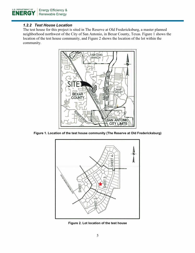
1.2.2 Test House Location The test house for this project is sited in The Reserve at Old Fredericksburg, a master planned neighborhood northwest of the City of San Antonio, in Bexar County, Texas. Figure 1 shows the location of the test house community, and Figure 2 shows the location of the lot within the community.
Figure 1. Location of the test house community (The Reserve at Old Fredericksburg)
Figure 2. Lot location of the test house
6
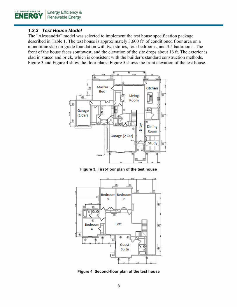
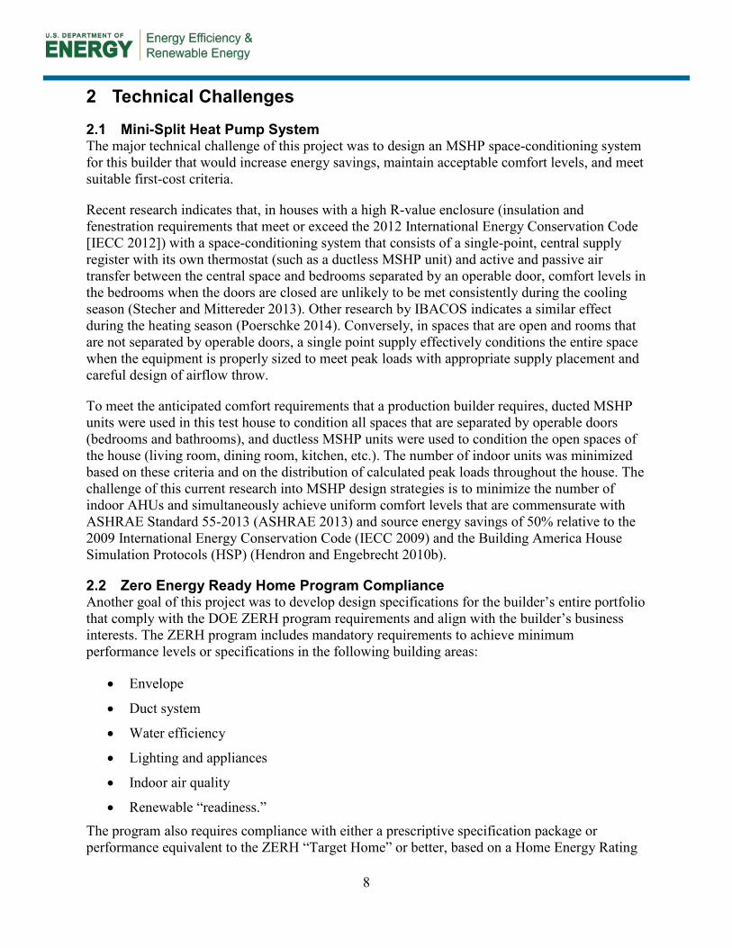
1.2.3 Test House Model The “Alessandria” model was selected to implement the test house specification package described in Table 1. The test house is approximately 3,600 ft2 of conditioned floor area on a monolithic slab-on-grade foundation with two stories, four bedrooms, and 3.5 bathrooms. The front of the house faces southwest, and the elevation of the site drops about 16 ft. The exterior is clad in stucco and brick, which is consistent with the builder’s standard construction methods. Figure 3 and Figure 4 show the floor plans; Figure 5 shows the front elevation of the test house.
Figure 3. First-floor plan of the test house
Figure 4. Second-floor plan of the test house

7
Figure 5. Front elevation of the test house
8
2 Technical Challenges
2.1 Mini-Split Heat Pump System The major technical challenge of this project was to design an MSHP space-conditioning system for this builder that would increase energy savings, maintain acceptable comfort levels, and meet suitable first-cost criteria.
Recent research indicates that, in houses with a high R-value enclosure (insulation and fenestration requirements that meet or exceed the 2012 International Energy Conservation Code [IECC 2012]) with a space-conditioning system that consists of a single-point, central supply register with its own thermostat (such as a ductless MSHP unit) and active and passive air transfer between the central space and bedrooms separated by an operable door, comfort levels in the bedrooms when the doors are closed are unlikely to be met consistently during the cooling season (Stecher and Mittereder 2013). Other research by IBACOS indicates a similar effect during the heating season (Poerschke 2014). Conversely, in spaces that are open and rooms that are not separated by operable doors, a single point supply effectively conditions the entire space when the equipment is properly sized to meet peak loads with appropriate supply placement and careful design of airflow throw.
To meet the anticipated comfort requirements that a production builder requires, ducted MSHP units were used in this test house to condition all spaces that are separated by operable doors (bedrooms and bathrooms), and ductless MSHP units were used to condition the open spaces of the house (living room, dining room, kitchen, etc.). The number of indoor units was minimized based on these criteria and on the distribution of calculated peak loads throughout the house. The challenge of this current research into MSHP design strategies is to minimize the number of indoor AHUs and simultaneously achieve uniform comfort levels that are commensurate with ASHRAE Standard 55-2013 (ASHRAE 2013) and source energy savings of 50% relative to the 2009 International Energy Conservation Code (IECC 2009) and the Building America House Simulation Protocols (HSP) (Hendron and Engebrecht 2010b).
2.2 Zero Energy Ready Home Program Compliance Another goal of this project was to develop design specifications for the builder’s entire portfolio that comply with the DOE ZERH program requirements and align with the builder’s business interests. The ZERH program includes mandatory requirements to achieve minimum performance levels or specifications in the following building areas:
• Envelope
• Duct system
• Water efficiency
• Lighting and appliances
• Indoor air quality
• Renewable “readiness.” The program also requires compliance with either a prescriptive specification package or performance equivalent to the ZERH “Target Home” or better, based on a Home Energy Rating
9
System (HERS®) Index score. DOE describes a ZERH as a “high-performance home which is so energy efficient, that a renewable energy system can offset all or most of its annual energy consumption.”2
Primary efforts focused on resolving any technical challenges to:
• Meeting the ZERH specification
• Evaluating the builder’s business processes
• Identifying any necessary changes to effectively construct and sell ZERHs
• Exploring design options to cost-effectively integrate MSHP systems into the builder’s current floor plans.
IBACOS and Imagine Homes evaluated the design and specification changes necessary for all the builder’s homes to comply with ZERH requirements (DOE 2014). Although many of the builder’s standard specifications already complied with the ZERH program requirements, other program requirements presented specific challenges for the builder, particularly in regard to the requirement for homes to be “renewable ready.”
2.3 Research Questions To address the technical challenges of this project, the research work was designed to answer the following questions:
• How effectively will a multihead MSHP design maintain uniform temperatures and relative humidity (RH) levels in all occupied spaces of a “high performance” test house?
• What is the homeowners’ perception of the temperatures and RH levels in the house?
• What are the business implications of adopting vented, unconditioned attic assemblies and MSHP heating and cooling in a region where unvented, conditioned attic assemblies are a key selling point for new homes and where gas heat is standard?
• What are some of the essential and cost-effective design changes to a typical production floor plan that can be made to leverage the respective distribution efficiencies of ducted and ductless MSHP space-conditioning systems?
• What are the technical and business implications of adopting ZERH as a standard specification?
2 http://www.energy.gov/eere/buildings/zero-energy-ready-home.
10
3 Mathematical and Modeling Methods
During the design phase of the test house, IBACOS performed a number of modeling applications and calculations to optimize the specification package and design details. The following key issues were addressed during design:
• Eliminate the cathedralized attic to reduce construction costs.
• Minimize the number of MSHP units and maintain adequate occupant comfort.
• Integrate an ERV into the mechanical system.
• Optimize the enclosure and mechanical strategies to meet the builder’s objectives.
• Address the mismatch of heating and cooling peak loads that was caused by the slab edge conditions.
IBACOS used the following modeling programs and calculation methods to complete the final design package and to determine potential design packages for compliance with the DOE ZERH program:
• Building Energy Optimization (BEopt™) software was used to: o Optimize thermal enclosure and mechanical system specifications
o Predict energy use and energy savings (NREL 2013a and 2014)
• THERM software was used to: o Specify the amount and location of slab edge insulation (THERM 2012)
• Air Conditioning Contractors of America (ACCA) Manuals were used to: o Calculate heating, ventilating, and air conditioning (HVAC) system loads
(Manual J; Rutkowski 2006)
o Select equipment (Manual S; Rutkowski 1995)
o Design the duct system (Manual S; Rutkowski 2009)
• REM/Rate energy modeling software was used to: o Predict the HERS Index of the test house and ZERH package options (AEC 2012,
2014).
3.1 Building Energy Optimization Software IBACOS used BEopt software to optimize the thermal enclosure and mechanical system specifications of the test house and to predict its energy consumption and energy savings relative to the HSP (NREL 2013a). One significant challenge in using BEopt for predicting energy use is the limitations of the program around zoned HVAC systems. The version of BEopt used at that time (Version 2.0.0.6) and earlier versions included no provision for modeling multiple thermal zones with separate thermostats; therefore, BEopt could not predict the possible benefits or liabilities from using a zoned system over a whole-house, single-zoned system. This presented a hurdle when predicting the performance of an MSHP space-conditioning strategy over a central, single-zoned strategy.
11
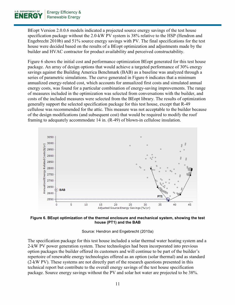
BEopt Version 2.0.0.6 models indicated a projected source energy savings of the test house specification package without the 2.0-kW PV system is 38% relative to the HSP (Hendron and Engebrecht 2010b) and 51% source energy savings with PV. The final specifications for the test house were decided based on the results of a BEopt optimization and adjustments made by the builder and HVAC contractor for product availability and perceived constructability.
Figure 6 shows the initial cost and performance optimization BEopt generated for this test house package. An array of design options that would achieve a targeted performance of 30% energy savings against the Building America Benchmark (BAB) as a baseline was analyzed through a series of parametric simulations. The curve generated in Figure 6 indicates that a minimum annualized energy-related cost, which accounts for annualized first costs and simulated annual energy costs, was found for a particular combination of energy-saving improvements. The range of measures included in the optimization was selected from conversations with the builder, and costs of the included measures were selected from the BEopt library. The results of optimization generally support the selected specification package for this test house, except that R-49 cellulose was recommended for the attic. This measure was not acceptable to the builder because of the design modifications (and subsequent cost) that would be required to modify the roof framing to adequately accommodate 14 in. (R-49) of blown-in cellulose insulation.
Figure 6. BEopt optimization of the thermal enclosure and mechanical system, showing the test
house (PT1) and the BAB
Source: Hendron and Engebrecht (2010a)
The specification package for this test house included a solar thermal water heating system and a 2-kW PV power generation system. These technologies had been incorporated into previous option packages the builder offered its customers and will continue to be part of the builder’s repertoire of renewable energy technologies offered as an option (solar thermal) and as standard (2-kW PV). These systems are not directly part of the research questions presented in this technical report but contribute to the overall energy savings of the test house specification package. Source energy savings without the PV and solar hot water are projected to be 38%.

12
IBACOS also used BEopt to develop optimized packages for compliance with the ZERH program. Figure 7 demonstrates a BEopt optimization of possible specifications for a ZERH-compliant design package for the Model 2247, a popular and smaller floor plan in the builder’s portfolio. Point 1 (PT1) in the optimization represents the builder’s standard specification (with PV), and Point 2 (PT2) represents one likely package of measures for a ZERH that was discussed with the builder (with PV). Point 3 (PT3) represents the package of measures used in the 2013 test house (with PV). Figure 8 represents the same optimization for the Model 3247, a popular midsized floor plan in the builder’s portfolio. Figure 9 represents the same optimization for the Model 3908, a popular and larger floor plan. Measure costs for all BEopt models are from the National Renewable Energy Laboratory’s National Residential Efficiency Measures Database Version 3.0.0 (NREL 2013b).
Figure 7. BEopt optimization of Model 2247, showing specifications for the BAB, the builder’s
standard (PT1), a likely ZERH (PT2), and the 2013 test house (PT3)
Figure 8. BEopt optimization of Model 3247, showing specifications for the BAB, the builder’s
standard (PT1), a likely ZERH (PT2), and the 2013 test house (PT3)

13
Figure 9. BEopt optimization of Model 3908, showing specifications for the BAB, the builder’s standard (PT1), a likely ZERH (PT2), and the 2013 test house (PT3)
3.2 THERM During the design phase of the test house, the impact and benefit of introducing insulation at the slab edge and foundation level were examined.
Because of the magnitude of the peak heating load that was calculated for this house during the design phase, the research team determined that an MSHP system that was properly sized for the peak cooling load would have insufficient capacity to meet the calculated load. To address this issue, either the heating load needed to be reduced or the size of the MSHP equipment needed to be increased. Additional insulation strategies were explored using ACCA Manual J load-sizing software (Rutkowski 2006), and ultimately the team decided to insulate the monolithic slab foundation. Several approaches to slab insulation were explored, including horizontal insulation under the slab and vertical insulation along the interior and exterior parts of the monolithic stem walls. Ultimately, a vertical insulation strategy was selected that reduced the peak heating load to be within the capacity of the specified MSHP equipment and integrated well with the physical construction of the house and the transition between the exterior walls and the foundation.
IBACOS used THERM, a two-dimensional building heat-transfer modeling software program developed by Lawrence Berkeley National Laboratory (THERM 2012), to calculate the amount of slab and foundation insulation to be installed. IBACOS chose this software because the physical site of the test house is steep (16-ft drop in elevation on the site) and the exposed edge of the slab and foundation varied from 1 ft high at the front of the house to 8 ft high at the back. The ACCA Manual J software (Rutkowski 2006) accounts for only a slab foundation at grade and cannot calculate the heating and cooling loads from a raised slab. To more accurately calculate the load and determine the most cost-effective amount of insulation to install, IBACOS used the THERM model to simulate the heat loss and gain for various insulation depths and thicknesses on the slab edge. Figure 10 and Figure 11 show the THERM outputs for the heating and cooling season performance for an assembly similar to the specified assembly, which ultimately consisted of 12 in. of vertical R-5 insulation installed around the entire perimeter of

14
the slab. No insulation was installed between the house and garage slabs or between the house and porch slabs.
Slab insulation was not considered for the ZERH specification, because the capacity of the preferred equipment was sufficient to meet both the cooling and heating calculated peak loads. The preferred equipment for the ZERH specification included a centrally-ducted air conditioner and furnace because of their lower costs and higher rated cooling efficiency compared to the MSHP system.
Figure 10. Winter performance of the slab insulation strategy. Design temperatures are 27°F
outdoors and 70°F indoors.
15
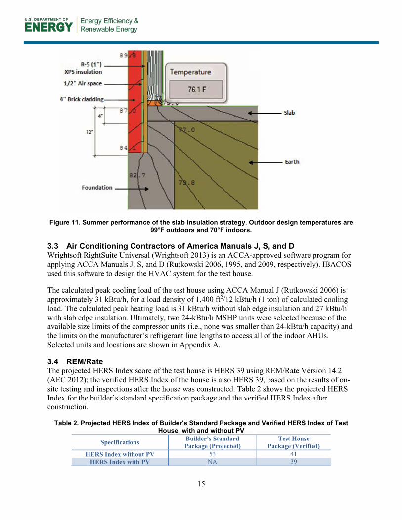
Figure 11. Summer performance of the slab insulation strategy. Outdoor design temperatures are
99°F outdoors and 70°F indoors.
3.3 Air Conditioning Contractors of America Manuals J, S, and D Wrightsoft RightSuite Universal (Wrightsoft 2013) is an ACCA-approved software program for applying ACCA Manuals J, S, and D (Rutkowski 2006, 1995, and 2009, respectively). IBACOS used this software to design the HVAC system for the test house.
The calculated peak cooling load of the test house using ACCA Manual J (Rutkowski 2006) is approximately 31 kBtu/h, for a load density of 1,400 ft2/12 kBtu/h (1 ton) of calculated cooling load. The calculated peak heating load is 31 kBtu/h without slab edge insulation and 27 kBtu/h with slab edge insulation. Ultimately, two 24-kBtu/h MSHP units were selected because of the available size limits of the compressor units (i.e., none was smaller than 24-kBtu/h capacity) and the limits on the manufacturer’s refrigerant line lengths to access all of the indoor AHUs. Selected units and locations are shown in Appendix A.
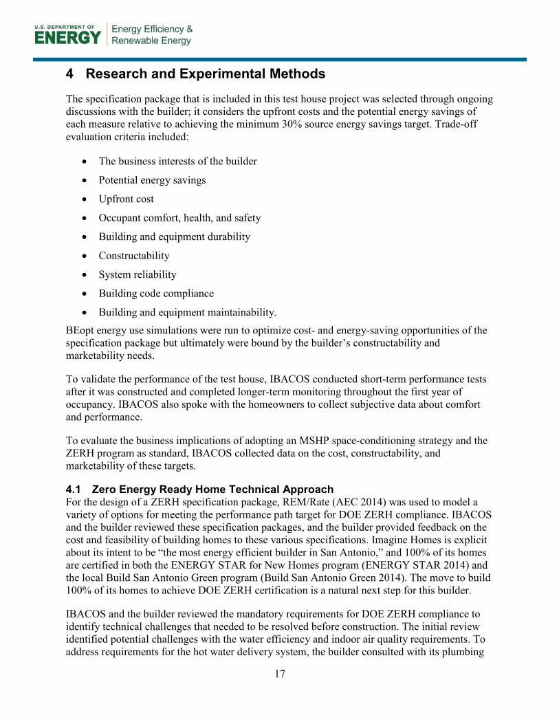
3.4 REM/Rate The projected HERS Index score of the test house is HERS 39 using REM/Rate Version 14.2 (AEC 2012); the verified HERS Index of the house is also HERS 39, based on the results of on-site testing and inspections after the house was constructed. Table 2 shows the projected HERS Index for the builder’s standard specification package and the verified HERS Index after construction.
Table 2. Projected HERS Index of Builder's Standard Package and Verified HERS Index of Test House, with and without PV
Specifications Builder’s Standard Package (Projected)
Test House Package (Verified)
HERS Index without PV 53 41 HERS Index with PV NA 39
16
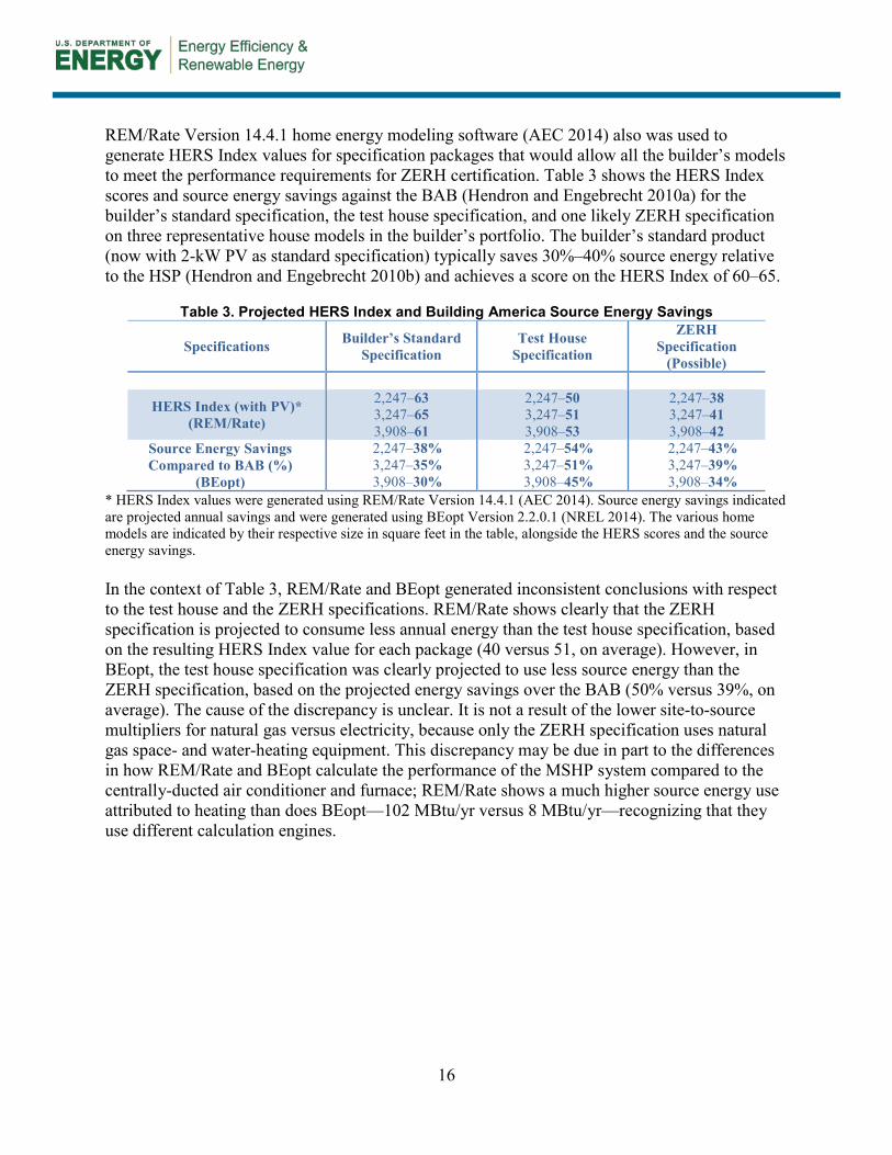
REM/Rate Version 14.4.1 home energy modeling software (AEC 2014) also was used to generate HERS Index values for specification packages that would allow all the builder’s models to meet the performance requirements for ZERH certification. Table 3 shows the HERS Index scores and source energy savings against the BAB (Hendron and Engebrecht 2010a) for the builder’s standard specification, the test house specification, and one likely ZERH specification on three representative house models in the builder’s portfolio. The builder’s standard product (now with 2-kW PV as standard specification) typically saves 30%–40% source energy relative to the HSP (Hendron and Engebrecht 2010b) and achieves a score on the HERS Index of 60–65.
Table 3. Projected HERS Index and Building America Source Energy Savings
Specifications Builder’s Standard Specification
Test House Specification
ZERH Specification
(Possible)
HERS Index (with PV)* (REM/Rate)
2,247–63 3,247–65 3,908–61
2,247–50 3,247–51 3,908–53
2,247–38 3,247–41 3,908–42
Source Energy Savings Compared to BAB (%)
(BEopt)
2,247–38% 3,247–35% 3,908–30%
2,247–54% 3,247–51% 3,908–45%
2,247–43% 3,247–39% 3,908–34%
* HERS Index values were generated using REM/Rate Version 14.4.1 (AEC 2014). Source energy savings indicated are projected annual savings and were generated using BEopt Version 2.2.0.1 (NREL 2014). The various home models are indicated by their respective size in square feet in the table, alongside the HERS scores and the source energy savings. In the context of Table 3, REM/Rate and BEopt generated inconsistent conclusions with respect to the test house and the ZERH specifications. REM/Rate shows clearly that the ZERH specification is projected to consume less annual energy than the test house specification, based on the resulting HERS Index value for each package (40 versus 51, on average). However, in BEopt, the test house specification was clearly projected to use less source energy than the ZERH specification, based on the projected energy savings over the BAB (50% versus 39%, on average). The cause of the discrepancy is unclear. It is not a result of the lower site-to-source multipliers for natural gas versus electricity, because only the ZERH specification uses natural gas space- and water-heating equipment. This discrepancy may be due in part to the differences in how REM/Rate and BEopt calculate the performance of the MSHP system compared to the centrally-ducted air conditioner and furnace; REM/Rate shows a much higher source energy use attributed to heating than does BEopt—102 MBtu/yr versus 8 MBtu/yr—recognizing that they use different calculation engines.
17
4 Research and Experimental Methods
The specification package that is included in this test house project was selected through ongoing discussions with the builder; it considers the upfront costs and the potential energy savings of each measure relative to achieving the minimum 30% source energy savings target. Trade-off evaluation criteria included:
• The business interests of the builder
• Potential energy savings
• Upfront cost
• Occupant comfort, health, and safety
• Building and equipment durability
• Constructability
• System reliability
• Building code compliance
• Building and equipment maintainability. BEopt energy use simulations were run to optimize cost- and energy-saving opportunities of the specification package but ultimately were bound by the builder’s constructability and marketability needs.
To validate the performance of the test house, IBACOS conducted short-term performance tests after it was constructed and completed longer-term monitoring throughout the first year of occupancy. IBACOS also spoke with the homeowners to collect subjective data about comfort and performance.
To evaluate the business implications of adopting an MSHP space-conditioning strategy and the ZERH program as standard, IBACOS collected data on the cost, constructability, and marketability of these targets.
4.1 Zero Energy Ready Home Technical Approach For the design of a ZERH specification package, REM/Rate (AEC 2014) was used to model a variety of options for meeting the performance path target for DOE ZERH compliance. IBACOS and the builder reviewed these specification packages, and the builder provided feedback on the cost and feasibility of building homes to these various specifications. Imagine Homes is explicit about its intent to be “the most energy efficient builder in San Antonio,” and 100% of its homes are certified in both the ENERGY STAR for New Homes program (ENERGY STAR 2014) and the local Build San Antonio Green program (Build San Antonio Green 2014). The move to build 100% of its homes to achieve DOE ZERH certification is a natural next step for this builder.
IBACOS and the builder reviewed the mandatory requirements for DOE ZERH compliance to identify technical challenges that needed to be resolved before construction. The initial review identified potential challenges with the water efficiency and indoor air quality requirements. To address requirements for the hot water delivery system, the builder consulted with its plumbing
18
partner to identify ways to minimize wasted water during hot water use. The builder also consulted with IBACOS, its local HERS rater, its HVAC partner, and U.S. Environmental Protection Agency Indoor airPLUS3 staff to identify the most cost-effective products and techniques for complying with the DOE ZERH indoor air quality requirements.
4.2 Mini-Split Heat Pump Technical Approach During the design of the test house, IBACOS documented business and market challenges associated with the builder’s choice of moving from a cathedralized attic assembly to a vented attic assembly with flat ceiling insulation and from a centrally-ducted furnace and air conditioner to a distributed MSHP space-conditioning system.
One of the greatest challenges indicated by the builder in the construction of the test house was the significantly higher first cost of the MSHP system over the builder’s standard system. To improve the appeal of using an MSHP system in future homes, the first cost of the installed system will need to be reduced.
Potential design changes to the builder’s floor plan were also explored to reduce the cost of the MSHP system by allowing for fewer MSHP indoor units to be used in the house. Ductless MSHP indoor units are typically less expensive and their rated efficiencies are higher (e.g., SEER, HSPF) than the ducted units. However, ductless units are most effective at conditioning open spaces and interconnected rooms without closed partitions—not areas such as multiple bedrooms that are connected via operable doors that may be closed (and might remain closed for extended periods). Therefore, to the extent possible, the design of the home should reflect an “open floor plan” scenario in which a minimal number of ductless units can be used to effectively condition the entire space. Even if a ducted indoor unit must be used for the bedrooms, reducing the overall number of indoor units will reduce the overall cost of the system.
4.3 Short-Term Test Methods To characterize the integrity of the thermal enclosure and measure the start-up performance of the HVAC system, IBACOS completed a number of short-term tests after the test house was constructed. Section 4.31 through Section 4.3.7 describe these tests.
4.3.1 Room-by-Room Supply Register Airflow (Ducted Units) IBACOS used a calibrated low-flow balometer (FlowBlaster Capture Hood Accessory for the Duct Blaster)4 to measure the airflow from each supply register in each room that was conditioned by a ducted MSHP unit. This testing device has an accuracy of ±5% of indicated flow or ±2 CFM, whichever is greater. The team then compared these measurements to the design airflow values from the ACCA Manual J heating and cooling load calculations (Rutkowski 2006) to determine if adequate airflow was reaching each zone of the house. The actual airflows represent the distribution of the system’s capacity as installed; the airflow cannot be adjusted without modifying the installed configuration of the ducts. Because low static pressures are required for the ducted MSHP units to operate properly, no adjustable dampers were installed in the duct runs. Although this requirement limits the adjustments that can be
3 U.S. Environmental Protection Agency Indoor airPLUS: www.epa.gov/indoorairplus/. 4 FlowBlaster Capture Hood Accessory for the Duct Blaster. Minneapolis, MN: The Energy Conservatory. www.energyconservatory.com/sites/default/files/documents/flowblaster_hi_res.pdf.

19
made to the delivered airflow to each room, it also allows for long-term measurements of the system “as installed” by the contractor.
4.3.2 Total Supply Airflow (Ductless Units) IBACOS determined the total supply airflow of each ductless MSHP unit by using the supply flow measurement with a powered flow hood testing protocol as defined in the Building America field monitoring protocol for MSHPs (Christensen et al. 2011). Then IBACOS compared these measurements to the manufacturer’s rated airflows for the units; the load calculation software does not currently have the capacity to input MSHP data for ACCA Manual S (Rutkowski 1995) equipment sizing and therefore cannot accurately calculate design airflows for the individual zones.
4.3.3 Duct Air Leakage The duct air leakage for each ducted MSHP unit was measured using a Minneapolis Duct Blaster5 and Minneapolis Blower Door.6 Total air leakage through the duct systems and total air leakage to the outside were measured. These tests were performed by the builder’s HERS Rater as routine tests for compliance with the ENERGY STAR for New Homes program. Determining the amount of air leaking through the duct system helps to characterize the air distribution system’s ability to deliver the proper amount of air to each zone.
4.3.4 Whole-Building Air Leakage The whole-house infiltration rate was measured using a single-point blower door test. This test was performed by the builder’s HERS rater, after the test house was constructed, using a Minneapolis Blower Door manufactured by The Energy Conservatory. The target test result is 2.58 ACH50, which is the average test result for the builder’s standard product. The measured air leakage in cubic feet per minute (cfm) will be converted to air changes per hour at the 50 Pa test pressure (ACH50) using the following equation:
( ) ,VOL6050CFM50ACH ×=
where
ACH50 = air changes per hour at 50 Pa test pressure
CFM50 = cubic feet per minute at 50 Pa test pressure
VOL = house volume
4.3.5 Room Pressures A digital manometer was used to measure the pressure difference between each bedroom and the central space of the house. Readings were taken with the interior partition door closed and the mechanical system operating in cooling mode on high fan speed (and while the HVAC system was not operating) to determine if sufficient air was being drawn through the over-door transfer
5 Minneapolis Duct Blaster. Minneapolis, MN: The Energy Conservatory. http://www.energyconservatory.com/products/duct-blaster%C2%AE-systems-and-accessories. 6 Minneapolis Blower Door. Minneapolis, MN: The Energy Conservatory. http://products.energyconservatory.com/blower-door-systems/.
20
grille above each bedroom and sufficient return air was reaching the central MSHP unit. Pressure readings should be below ±3 Pa during these operating conditions.
4.3.6 Energy Recovery Ventilator Airflow Balancing Fresh air is being supplied to the test house by two installed Panasonic FV-04VE1 spot ERV units,7 which are small units installed in a ceiling cavity similar to standard bath fans. One ERV unit is installed in the breakfast nook on the first floor next to the kitchen; the other unit is installed in the central game room space on the second floor. The ERV units will run continuously and will supply the house with 74 cfm of outdoor air. To verify these units are supplying the proper amount of air to the house, the airflow of each unit was measured and balanced after it was installed. Measurements were performed using a pitot tube and a DG-700 Pressure and Flow Gauge (manometer).8 Velocity pressure measurements (in Pascals) were collected in the supply and return ducts of the ERV, and the installed balancing dampers were adjusted to balance the flows in these ducts. The velocity pressure measurements were averaged using measurements collected at different points inside the diameter of each duct and were converted to airflow velocity values (in feet per minute) using the conversion charts supplied by the manufacturer. Airflow rates were calculated by multiplying airflow velocity by the duct cross-sectional area in square feet.
4.3.7 Equipment Table 4 lists the equipment that was used to conduct the short-term performance tests for the 2013 test house.
Table 4. Equipment Used for Short-Term Performance Tests Measurement Equipment Used Accuracy
Whole-House Air Leakage Minneapolis Blower Door ±3% Duct Air Leakage Minneapolis Duct Blaster ±3%
Supply Airflow (Ducted MSHP Units) Minneapolis Duct Blaster ±3%
Supply Airflow (Ductless MSHP Units)
Minneapolis Duct Blaster; tachometer with proximity sensor
±3% (Duct Blaster) ±2% (tachometer with proximity
sensor)
ERV Airflow Balancing DG-700 Pressure and Flow Gauge (manometer); pressure pan ±10%
4.4 Long-Term Monitoring and Data Collection Long-term monitoring efforts at the builder’s test house were aimed at measuring how well the MSHP space-conditioning system maintained adequate comfort levels in all thermal zones. Temperature and RH sensors were installed in all rooms and at each thermostat, and electricity consumption measurements were collected from all the indoor AHUs and outdoor compressor units. An outdoor weather station was installed to collect the temperature and RH data that were necessary to evaluate the comfort performance of the MSHP system. A primary data logger collected data from installed sensors and recorded measurements at 1-min, 15-min, 1-h, and daily
7 Panasonic FV-04VE1 ERV. Chesapeake, VA: Panasonic Corporation. http://www2.panasonic.com/webapp/wcs/stores/servlet/ModelDetail?storeId=11201&catalogId=13051&itemId=175432&catGroupId=119516&surfModel=FV-04VE1&displayTab=O. 8 DG-700 Pressure and Flow gauge. Minneapolis, MN: The Energy Conservatory. http://www.energyconservatory.com/sites/default/files/software/dg700simulatorman.pdf.

21
intervals as needed. Data were collected for a 10-month period (April 2014 through February 2015).
Appendix B shows the design of the long-term monitoring system, including the locations of each sensor and the type of data to be collected from each.
The electrician and the project team installed monitoring wiring and equipment during the construction of the test house, and the project team commissioned the equipment after construction was completed. A combination of wired and wireless sensors was used to capture the needed data and minimize installation labor.
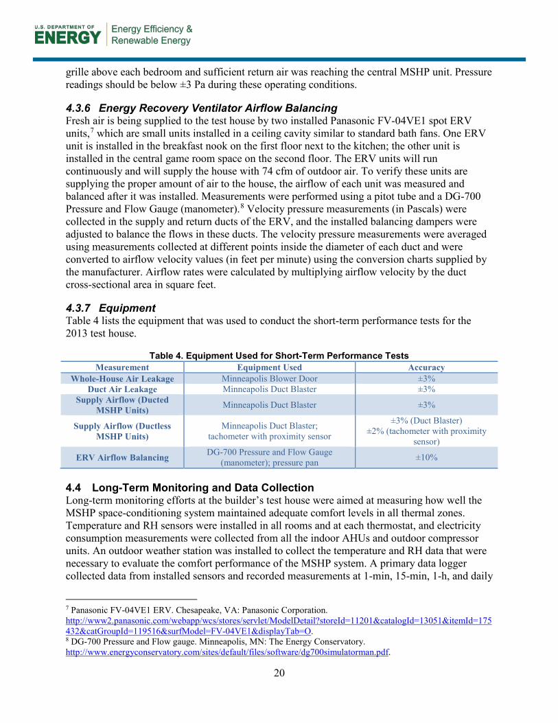
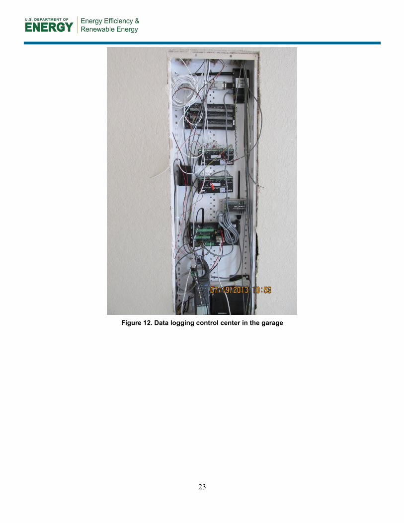
Table 5 lists the long-term monitoring equipment that was installed in this test house. Figure 12 through Figure 14 show examples of installed monitoring equipment.

22
Table 5. Long-Term Monitoring Equipment Installed in the Test House Measurement Equipment Used Manufacturer Model Number Accuracy
Whole-House Electrical Watt node power meter Continental Control Systems WNB-3D-P 100 HZ output ±0.5%
Whole-House Electrical Split core current transformer Continental Control Systems ACT-0750-100 ±0.75%
Compressor Electrical (2 Units) Watt node power meter Continental Control Systems WNB-3D-P 100 HZ output ±0.5%
Compressor Electrical (2 Units) Split core current transformer Continental Control Systems ACT-0750-100 ±0.75% Distributed Air Handler Electrical (6
Units) Watt node power meter Continental Control Systems WNB-3D-P 100 HZ output ±0.5%
Distributed Air Handler Electrical (6 Units) Split core current transformer Continental Control Systems ACT-0750-100 ±0.75%
Interior Door Status (Open or Closed) Wireless magnetic sensor Monnit SCM-91A-0MP NA
ERV Electrical Watt node power meter Continental Control Systems WNB-3D-P 100 HZ output ±0.5%
ERV Electrical Split core current transformer Continental Control Systems ACT-0750-100 ±0.75%
Outdoor Temperature and RH Temperature and RH sensor Vaisala HMP60A12A0A3B0 ±0.6°C, ±3% RH
Outdoor Unit Radiation Shield Radiation shield from solar radiation Campbell Scientific 41303-5A NA
Global Horizontal Solar Radiation National Oceanic and Atmospheric Administration weather station readings for San Antonio International Airport (TX)
Data Collection Main Logger Campbell Scientific CR1000 ±0.06% Data Collection Multiplexer Campbell Scientific AM 16/32 SDA-SWA8 NA
Space Air Temperature and RH Wireless Humidity Sensor Monnit SCM-91A-0HA ±2% Data Collection Wireless Gateway Monnit GCM-SMG NA
23
Figure 12. Data logging control center in the garage
24
Figure 13. Wireless temperature and RH sensor at the thermostat
Figure 14. Room temperature and RH sensor
25
5 Results
The results of short-term testing and long-term monitoring of the test house, as well as the costs analysis of the MSHP space-conditioning system and likely ZERH specification, are discussed in Section 5.1.
5.1 Short-Term Test Results IBACOS collected data for the following short-term test results after the test house was constructed.
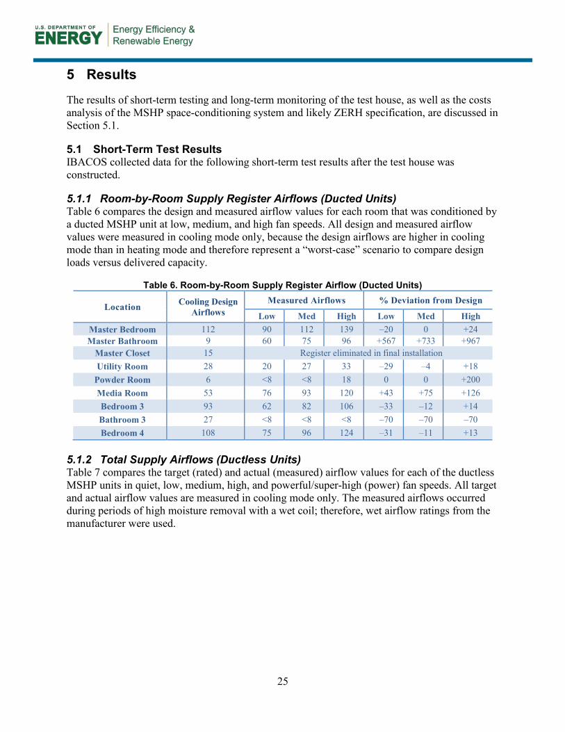
5.1.1 Room-by-Room Supply Register Airflows (Ducted Units) Table 6 compares the design and measured airflow values for each room that was conditioned by a ducted MSHP unit at low, medium, and high fan speeds. All design and measured airflow values were measured in cooling mode only, because the design airflows are higher in cooling mode than in heating mode and therefore represent a “worst-case” scenario to compare design loads versus delivered capacity.
Table 6. Room-by-Room Supply Register Airflow (Ducted Units)
Location Cooling Design Airflows
Measured Airflows % Deviation from Design
Low Med High Low Med High Master Bedroom 112 90 112 139 –20 0 +24 Master Bathroom 9 60 75 96 +567 +733 +967
Master Closet 15 Register eliminated in final installation Utility Room 28 20 27 33 –29 –4 +18
Powder Room 6 <8 <8 18 0 0 +200 Media Room 53 76 93 120 +43 +75 +126 Bedroom 3 93 62 82 106 –33 –12 +14 Bathroom 3 27 <8 <8 <8 –70 –70 –70 Bedroom 4 108 75 96 124 –31 –11 +13
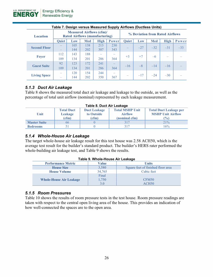
5.1.2 Total Supply Airflows (Ductless Units) Table 7 compares the target (rated) and actual (measured) airflow values for each of the ductless MSHP units in quiet, low, medium, high, and powerful/super-high (power) fan speeds. All target and actual airflow values are measured in cooling mode only. The measured airflows occurred during periods of high moisture removal with a wet coil; therefore, wet airflow ratings from the manufacturer were used.
26
Table 7. Design versus Measured Supply Airflows (Ductless Units)
Location Measured Airflows (cfm)/
Rated Airflows (manufacturing) % Deviation from Rated Airflows
Quiet Low Med High Power Quiet Low Med High P o w e r
Second Floor – 105 138 213 230 – –27 –32 –31 –33 – 144 202 307 343
Foyer 112 143 188 – –
+3 +7 –6 – – 109 134 201 286 364
Guest Suite 92 123 172 241 –
–16 –8 –14 –16 – 109 134 201 286 364
Living Space – 120 154 244 –
– –17 –24 –30 – – 144 202 350 367 5.1.3 Duct Air Leakage Table 8 shows the measured total duct air leakage and leakage to the outside, as well as the percentage of total unit airflow (nominal) represented by each leakage measurement.
Table 8. Duct Air Leakage
Unit Total Duct Leakage
(cfm)
Duct Leakage to Outside
(cfm)
Total MSHP Unit Airflow
(nominal cfm)
Total Duct Leakage per MSHP Unit Airflow
(%) Master Suite 66 0 317 21% Bedrooms 51 0 317 16%
5.1.4 Whole-House Air Leakage The target whole-house air leakage result for this test house was 2.58 ACH50, which is the average test result for the builder’s standard product. The builder’s HERS rater performed the whole-building air leakage test, and Table 9 shows the results.
Table 9. Whole-House Air Leakage Performance Metric Value Units
House Size 3,580 Square feet of finished floor area House Volume 34,765 Cubic feet
Whole-House Air Leakage Final 1,750 CFM50
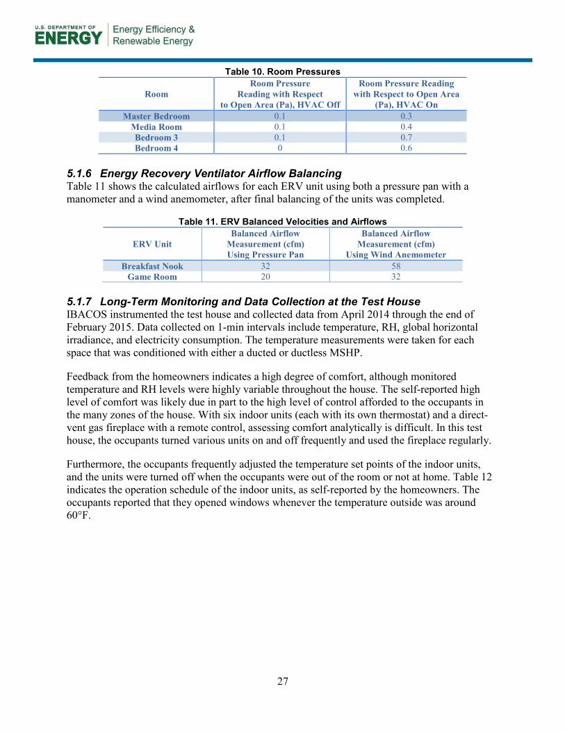
3.0 ACH50 5.1.5 Room Pressures Table 10 shows the results of room pressure tests in the test house. Room pressure readings are taken with respect to the central open living area of the house. This provides an indication of how well-connected the spaces are to the open area.
27
Table 10. Room Pressures
Room Room Pressure
Reading with Respect to Open Area (Pa), HVAC Off
Room Pressure Reading with Respect to Open Area
(Pa), HVAC On Master Bedroom 0.1 0.3
Media Room 0.1 0.4 Bedroom 3 0.1 0.7 Bedroom 4 0 0.6
5.1.6 Energy Recovery Ventilator Airflow Balancing Table 11 shows the calculated airflows for each ERV unit using both a pressure pan with a manometer and a wind anemometer, after final balancing of the units was completed.
Table 11. ERV Balanced Velocities and Airflows
ERV Unit Balanced Airflow
Measurement (cfm) Using Pressure Pan
Balanced Airflow Measurement (cfm)
Using Wind Anemometer Breakfast Nook 32 58
Game Room 20 32 5.1.7 Long-Term Monitoring and Data Collection at the Test House IBACOS instrumented the test house and collected data from April 2014 through the end of February 2015. Data collected on 1-min intervals include temperature, RH, global horizontal irradiance, and electricity consumption. The temperature measurements were taken for each space that was conditioned with either a ducted or ductless MSHP.
Feedback from the homeowners indicates a high degree of comfort, although monitored temperature and RH levels were highly variable throughout the house. The self-reported high level of comfort was likely due in part to the high level of control afforded to the occupants in the many zones of the house. With six indoor units (each with its own thermostat) and a direct-vent gas fireplace with a remote control, assessing comfort analytically is difficult. In this test house, the occupants turned various units on and off frequently and used the fireplace regularly.
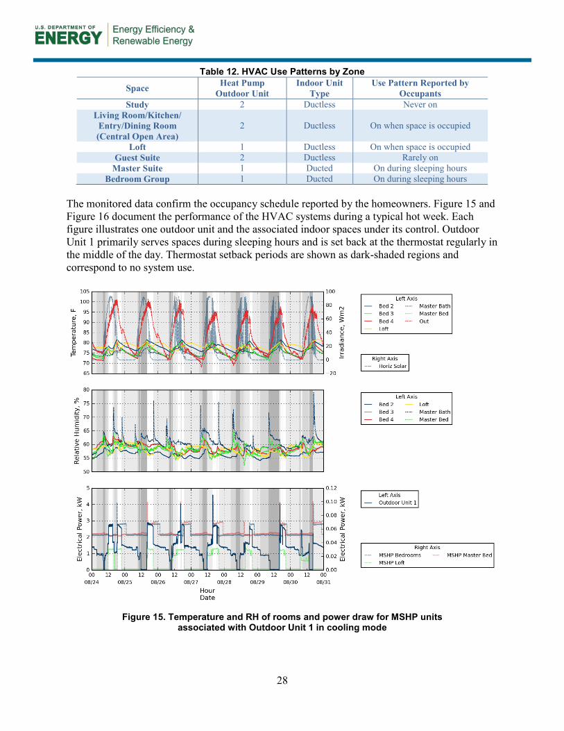
Furthermore, the occupants frequently adjusted the temperature set points of the indoor units, and the units were turned off when the occupants were out of the room or not at home. Table 12 indicates the operation schedule of the indoor units, as self-reported by the homeowners. The occupants reported that they opened windows whenever the temperature outside was around 60°F.
28
Table 12. HVAC Use Patterns by Zone
Space Heat Pump Outdoor Unit
Indoor Unit Type
Use Pattern Reported by Occupants
Study 2 Ductless Never on Living Room/Kitchen/
Entry/Dining Room (Central Open Area)
2 Ductless On when space is occupied
Loft 1 Ductless On when space is occupied Guest Suite 2 Ductless Rarely on
Master Suite 1 Ducted On during sleeping hours Bedroom Group 1 Ducted On during sleeping hours
The monitored data confirm the occupancy schedule reported by the homeowners. Figure 15 and Figure 16 document the performance of the HVAC systems during a typical hot week. Each figure illustrates one outdoor unit and the associated indoor spaces under its control. Outdoor Unit 1 primarily serves spaces during sleeping hours and is set back at the thermostat regularly in the middle of the day. Thermostat setback periods are shown as dark-shaded regions and correspond to no system use.
Figure 15. Temperature and RH of rooms and power draw for MSHP units
associated with Outdoor Unit 1 in cooling mode

29
Figure 16. Temperature and RH of rooms and power draw for MSHP units
associated with Outdoor Unit 2 in cooling mode
Individual indoor units were examined to determine the room-to-room temperature variations. The primary living space on the first floor is a large, open space that is conditioned by one ductless AHU (served by Outdoor Unit 2) that includes the living room, kitchen, dining room, and entry. This analysis focuses on the temperature uniformity among these spaces.

30
In heating mode, the temperature profiles for the rooms associated with Outdoor Unit 2 were controlled primarily by the fireplace; this resulted in temperature excursions to other rooms that exceeded 6°F. Figure 17 illustrates the ∆t to each room that was served by the ductless unit in the living room near the fireplace during a sample time period. The temperature deviations increased relative to the living room in the top segment of the figure. The rooms far from the fireplace did not receive much heat from it. The unshaded regions correspond to times when the fireplace was generally on. The temperature fluctuations appeared to increase in magnitude only when the fireplace was on, and although the ductless indoor unit operated, the AHU did not appear to have a large impact on the temperature of the spaces. The temperature excursions in this instance do not represent a comfort issue because the occupants initialized the fireplace and did not complain.
Figure 17. Fireplace and MSHP operation and associated
living area temperatures during the heating season

31
During cooling mode, the ductless unit of the living room appears to adequately condition the adjoining open spaces. Figure 18 shows a typical daily temperature profile for the open living space, which includes the living room, dining room, kitchen, and entryway. The single delivery point for conditioned air was apparently adequate to uniformly condition the spaces. The temperature differences between rooms served by the unit rarely exceeded 0.5°F, except during events that were presumed to be cooking periods in the kitchen.
Figure 18. Temperature differences and runtime profiles for primary living space in cooling mode
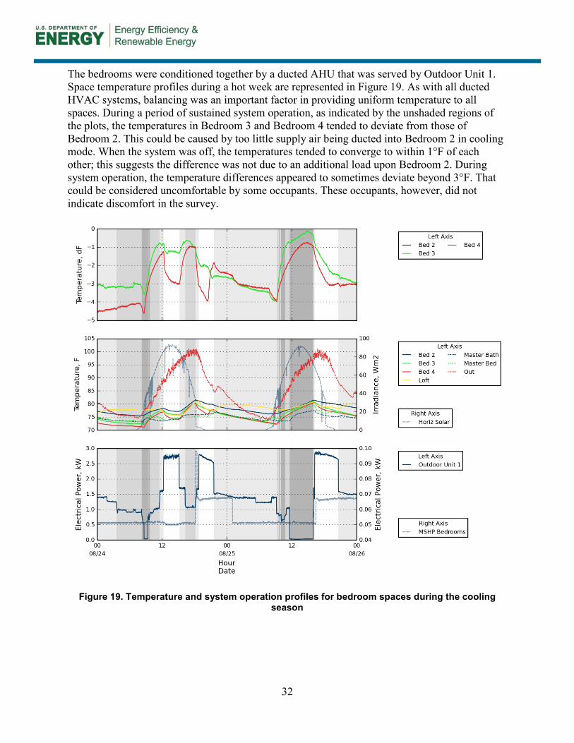
32
The bedrooms were conditioned together by a ducted AHU that was served by Outdoor Unit 1. Space temperature profiles during a hot week are represented in Figure 19. As with all ducted HVAC systems, balancing was an important factor in providing uniform temperature to all spaces. During a period of sustained system operation, as indicated by the unshaded regions of the plots, the temperatures in Bedroom 3 and Bedroom 4 tended to deviate from those of Bedroom 2. This could be caused by too little supply air being ducted into Bedroom 2 in cooling mode. When the system was off, the temperatures tended to converge to within 1°F of each other; this suggests the difference was not due to an additional load upon Bedroom 2. During system operation, the temperature differences appeared to sometimes deviate beyond 3°F. That could be considered uncomfortable by some occupants. These occupants, however, did not indicate discomfort in the survey.
Figure 19. Temperature and system operation profiles for bedroom spaces during the cooling season

33
Figure 20 illustrates typical temperatures in the bedrooms in heating mode and illustrates a fairly consistent 2°F difference between Bedroom 3 and Bedroom 4. In heating mode, the balancing of the system that served the bedrooms appeared to be more uniform than in cooling mode; temperature deviations generally indicated less than 3°F. Unshaded periods indicate when the MSHP was on.
Figure 20. Bedroom temperature deviations during the heating season
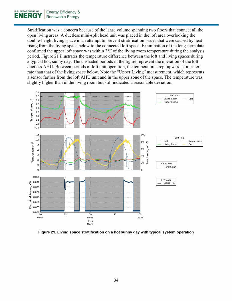
34
Stratification was a concern because of the large volume spanning two floors that connect all the open living areas. A ductless mini-split head unit was placed in the loft area overlooking the double-height living space in an attempt to prevent stratification issues that were caused by heat rising from the living space below to the connected loft space. Examination of the long-term data confirmed the upper loft space was within 2°F of the living room temperature during the analysis period. Figure 21 illustrates the temperature difference between the loft and living spaces during a typical hot, sunny day. The unshaded periods in the figure represent the operation of the loft ductless AHU. Between periods of loft unit operation, the temperature crept upward at a faster rate than that of the living space below. Note the “Upper Living” measurement, which represents a sensor farther from the loft AHU unit and in the upper zone of the space. The temperature was slightly higher than in the living room but still indicated a reasonable deviation.
Figure 21. Living space stratification on a hot sunny day with typical system operation
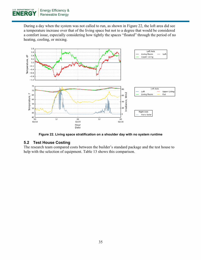
35
During a day when the system was not called to run, as shown in Figure 22, the loft area did see a temperature increase over that of the living space but not to a degree that would be considered a comfort issue, especially considering how tightly the spaces “floated” through the period of no heating, cooling, or mixing.
Figure 22. Living space stratification on a shoulder day with no system runtime
5.2 Test House Costing The research team compared costs between the builder’s standard package and the test house to help with the selection of equipment. Table 13 shows this comparison.
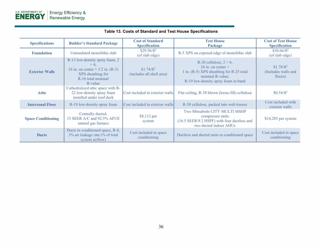
36
Table 13. Costs of Standard and Test House Specifications
Specifications Builder’s Standard Package Cost of Standard Specification
Test House Package
Cost of Test House Specification
Foundation Uninsulated monolithic slab $29.56/ft2
(of slab edge) R-5 XPS on exposed edge of monolithic slab $30.66/ft2
(of slab edge)
Exterior Walls
R-13 low-density spray foam, 2 × 4,
16 in. on center + 1/2 in. (R-3) XPS sheathing for R-16 total nominal
R-value
$1.74/ft2
(includes all shell area)
R-20 cellulose, 2 × 6, 24 in. on center +
1 in. (R-5) XPS sheathing for R-25 total nominal R-value;
R-19 low-density spray foam in band
$1.78/ft2
(Includes walls and floors)
Attic Cathedralized attic space with R-
22 low-density spray foam installed under roof deck
Cost included in exterior walls Flat ceiling, R-38 blown (loose-fill) cellulose $0.54/ft2
Interzonal Floor R-19 low-density spray foam Cost included in exterior walls R-50 cellulose, packed into web trusses Cost included with exterior walls
Space Conditioning Centrally ducted,
15 SEER A/C and 92.5% AFUE natural gas furnace
$8,112 per system
Two Mitsubishi CITY MULTI MSHP compressor units
(16.5 SEER/9.2 HSPF) with four ductless and two ducted indoor AHUs
$14,285 per system
Ducts Ducts in conditioned space, R-8, 3% air leakage rate (% of total
system airflow)
Cost included in space conditioning Ductless and ducted units in conditioned space Cost included in space
conditioning
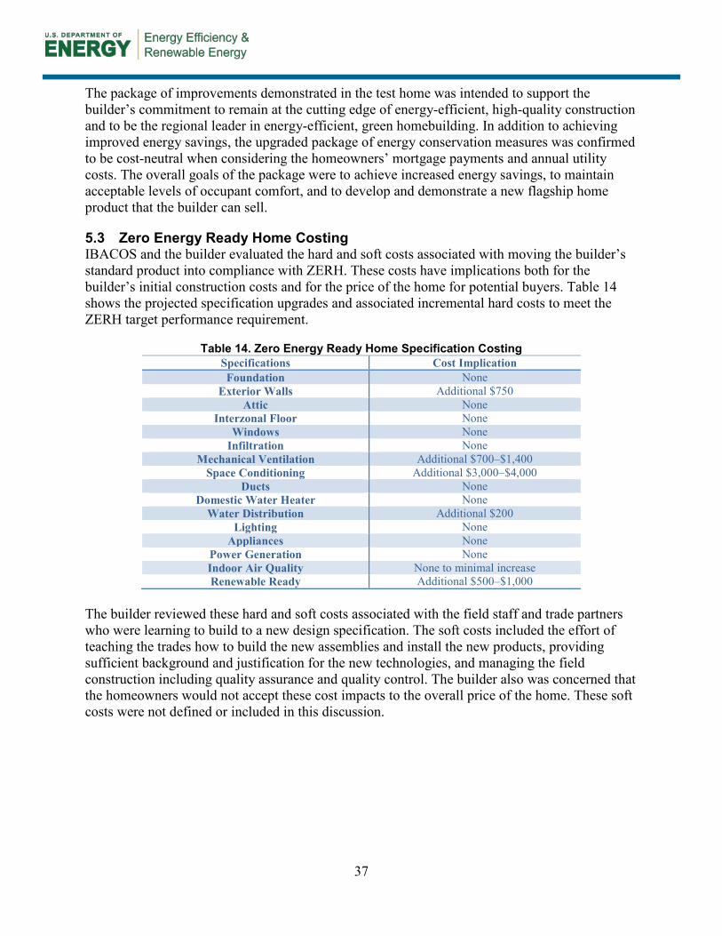
37
The package of improvements demonstrated in the test home was intended to support the builder’s commitment to remain at the cutting edge of energy-efficient, high-quality construction and to be the regional leader in energy-efficient, green homebuilding. In addition to achieving improved energy savings, the upgraded package of energy conservation measures was confirmed to be cost-neutral when considering the homeowners’ mortgage payments and annual utility costs. The overall goals of the package were to achieve increased energy savings, to maintain acceptable levels of occupant comfort, and to develop and demonstrate a new flagship home product that the builder can sell.
5.3 Zero Energy Ready Home Costing IBACOS and the builder evaluated the hard and soft costs associated with moving the builder’s standard product into compliance with ZERH. These costs have implications both for the builder’s initial construction costs and for the price of the home for potential buyers. Table 14 shows the projected specification upgrades and associated incremental hard costs to meet the ZERH target performance requirement.
Table 14. Zero Energy Ready Home Specification Costing Specifications Cost Implication Foundation None
Exterior Walls Additional $750 Attic None
Interzonal Floor None Windows None
Infiltration None Mechanical Ventilation Additional $700–$1,400
Space Conditioning Additional $3,000–$4,000 Ducts None
Domestic Water Heater None Water Distribution Additional $200
Lighting None Appliances None
Power Generation None Indoor Air Quality None to minimal increase Renewable Ready Additional $500–$1,000
The builder reviewed these hard and soft costs associated with the field staff and trade partners who were learning to build to a new design specification. The soft costs included the effort of teaching the trades how to build the new assemblies and install the new products, providing sufficient background and justification for the new technologies, and managing the field construction including quality assurance and quality control. The builder also was concerned that the homeowners would not accept these cost impacts to the overall price of the home. These soft costs were not defined or included in this discussion.

38
6 Discussion
6.1 Mini-Split Heat Pump Performance To validate that acceptable comfort has been achieved in the test house, IBACOS compared temperature and RH readings from the bedrooms and other remote thermal zones to the temperature and RH readings collected at the central, wall-mounted thermostat locations for each indoor AHU. A temperature deviation greater than ±2°F from the central thermostat is considered to be too high or too low in this analysis. Based on the measured results, the overall performance of the MSHP was sufficient to maintain comfortable indoor conditions for the occupants. Although some periods showed a temperature deviation greater than ±2°F from the thermostat, the occupants self-reported that they were “extremely satisfied” with the overall comfort in their home. The high degree of individualized comfort control between rooms perhaps provided a greater sense of comfort. These occupants also may have simply found the indoor comfort conditions to be favorable.
Electricity use data of the outdoor compressor and indoor AHUs was collected to calculate system runtimes. The measured data show that system runtime was sufficient to condition the home within the comfort range of the occupants, and the system varied in power consumption according to the capacity needed to condition the indoor space. The equipment capacity provided sufficient comfort; in fact, the two 2-kBtu/h outdoor condensing units were oversized for the peak cooling and heating loads of the house. In future houses using MSHP systems, it would be preferable to design the floor plan and HVAC layout to more closely “right size” the equipment to achieve successful comfort and minimize the number of indoor AHUs and subsequent cost of the installed system.
The data also clearly show that temperature drift during periods of system inactivity was minor and that comfort was adequately maintained during these periods of time. This mild temperature drift is likely attributable to the improved thermal enclosure and reduced heat gain or loss over time.
Although the RH levels vary greatly between some rooms (as much as 20% RH), the occupants have self-reported high comfort levels even during periods of higher humidity (including RH higher than 65%). This subjective method of reporting comfort calls into question the necessity for maintaining uniform comfort conditions between rooms and poses the questions about how much influence controllability and the subjective experiences of comfort must be weighted in the design and assessment of comfort systems in homes.
The homeowners seemed to be happy and comfortable with the MSHP system. Based on their feedback, the MSHP indoor units in this home are operated or turned off as determined by the occupants’ needs. The homeowners report they are “extremely satisfied” with the performance of the system. Windows are opened when needed, and the central living room ceiling fan is the preferred choice when space temperatures are slightly elevated. Two of the six AHUs remain off most of the time. The homeowners’ feedback clearly indicates that they appreciate and regularly use the individual unit control to achieve comfort satisfaction.
39
6.2 Mini-Split Heat Pump Constructability, Marketability, and Cost IBACOS talked with the builder about the specific market benefits and challenges for an MSHP system that surround cost, constructability, homebuyer interest (aesthetics/functionality), energy savings, and durability. Based on feedback from the builder, the greatest market benefit of the MSHP system is telling the “story of performance” and how the MSHP system represents the cutting edge in HVAC system technology and design. The builder believes the MSHP ductless units clearly are high-efficiency units and allow for great design flexibility related to placement of the indoor AHUs. The builder also finds the MSHP system offers the buyer a high level of individual control of room temperatures, with quiet operation and low energy use. In marketing its homes, the builder is confident that buyers are getting a high value, high-performance product. Many buyers are also pleased that the ductless system eliminates ductwork, because they view ducts as dirty and as contributing dust and other allergens into the house.
Feedback from the test house homeowners confirms these benefits. The homeowners were quite pleased with the performance of the system and made great use of the individual control of the indoor AHUs. Self-reported comfort levels were high.
The MSHP system presents distinct market challenges that have deterred the builder from widespread adoption of the technology. Perhaps the most significant challenge is the upfront cost of the system, which is significantly higher than the builder’s standard system. Although the cost of an MSHP system can be comparable to that of a standard central system, achieving cost equity requires that the number of indoor AHUs be significantly reduced. This would present an additional challenge to providing temperature uniformity around the house, especially for rooms with closed doors (i.e., bedrooms). Another significant market-acceptance challenge is the appearance of the indoor ductless AHUs. These are considered by many potential buyers to be unappealing or unattractive. Although the “high-performance story” can convince some buyers to overlook the aesthetics of the units, many buyers are deterred from purchasing houses with this equipment installed. Ducted AHUs could be one acceptable alternative in those situations, but the lower efficiency associated with the ducted units is unacceptable to this builder.
Another potential challenge with the MSHP systems is the difficulty of regularly cleaning the filters in the indoor units. The filters must be removed and cleaned every few months to maintain the units in proper working order.
One final challenge that remains for this production builder is eliminating the cathedralized attic assembly, which is a major selling point in this market and has become common in many homes in the San Antonio area. Cathedralized attic assemblies tell a performance story that is much more tangible and compelling to potential buyers than the MSHP story. On hot days, the builder’s salespeople place a chocolate Easter bunny in the attic space and bring potential buyers into the attic to observe how the bunny does not melt as it would in a typical hot, vented attic. Although the vented attic assembly has a higher R-value than the cathedralized attic assembly, the chocolate Easter bunny survival story has a big impact with customers. Until the builder has an equally compelling story to tell about the MSHP and vented attic strategies, the builder prefers the cathedralized attic and the central furnace and air conditioner.
The builder reported that the overall test house space-conditioning/insulation strategy using the MSHP system and vented attic cost slightly higher than 1% more of the builder’s standard

40
strategy. Although the MSHP and ERV units cost significantly more than the standard systems, the insulation strategy (walls and attic) costs significantly less than the builder’s standard. From past experience, the builder is familiar with how to install a vented attic assembly, and the test home construction details overall were similar to the standard practice. Construction of the test house was therefore relatively easy for the builder. One exception was the attic hatch assembly, which needed to have atypically high end dams installed to accommodate the additional attic insulation. The required detail was unfamiliar to the builder, and it took additional time to resolve. Going forward, this detail will no longer be an issue because the builder has now been through the learning curve.
The fundamental goal of a space-conditioning system is to provide acceptable comfort levels throughout the home. The installed cost of the system must be acceptable to the builder and the owner. The efficiency of the system must also be optimized to, in time, offset any cost premium associated with energy improvements to the home. When a space-conditioning system can meet these three criteria, it is likely to be successfully integrated into a builder’s standard product.
To the extent possible, this builder will endeavor to integrate MSHP equipment into its home plans without design changes; however, design changes to the floor plans are anticipated to be necessary in many cases to meet several important objectives: to minimize the number of indoor (and possibly outdoor) units, to use a higher percentage of ductless indoor units, and ultimately to minimize cost and maximize the efficiency of the system. The builder has expressed a willingness to evaluate potential floor plan changes but has made no firm commitment to changing a floor plan design.
Early in the design phase for the test house, the project team determined that the builder’s standard cathedralized attic would be replaced with a vented attic assembly that uses a blown-in cellulose insulation product on the horizontal plane. This was a difficult decision for the builder because the cathedralized attic assembly is a proven selling point for customers. However, the cost of the vented attic assembly was significantly lower than that of the cathedralized attic assembly. At the same time, higher R-values could be achieved with cellulose insulation than with low-density spray foam. Ultimately, the test house attic decision was made based upon cost and upon the opportunity to simplify the space-conditioning system and bring it into conditioned space by using an MSHP system.
The test house is the first speculative house constructed by this builder using an MSHP system. Although more expensive than a conventional fully ducted split system, the MSHP system offered the design flexibility that is necessary to integrate with the current floor plan with minimal design changes. Extensive bulkheads and structural changes that might be required for a conventional ducted system to be pulled into the conditioned space were not required for the MSHP system.
To better integrate MSHP systems into future home designs, the builder has acknowledged that interior floor plan accommodations could be made to embrace the air distribution characteristics of MSHP systems, particularly ductless units. This would ultimately reduce the number of indoor units that are needed to effectively condition the entire living space.
41
The builder feels that its marketing of the well-sealed, semiconditioned attic benefits greatly from the “wow factor” of the chocolate bunny demonstration, and it positively impacts the marketing of the overall home. A vented attic approach would introduce change with which the builder is uncomfortable. The builder would need some way to not make the deletion of the cathedralized attic appear to be a detriment. Over the last 6 years, this market has moved to where a lot of builders are offering the foam-insulated semiconditioned attic space. With the chocolate bunny marketing, buyers can easily perceive the benefits of this builder’s standard attic. The builder also feels that a radically different yet affordable space-conditioning system approach would be needed, rather than simply providing chases or furr-downs (dropped ceilings) to serve a conventionally ducted central HVAC system, to convince buyers that a vented attic system is beneficial. Looking forward, the builder feels that the cost for the MSHP systems is still too high, given the desire or demand seen from homebuyers. At the time of this project (2014), the builder has only two prospective buyers who are requesting costing for MSHP systems in their homes. The MSHP system goes hand-in-hand with the vented attic. It negates the need for a cathedralized attic to bring ductwork and equipment inside the thermal enclosure. Such challenges with its market will likely have greater influence on the builder’s choices moving forward with new homes than the results from the test house. The builder will most likely not move forward with the MSHP system or with the vented attic.
The builder educated the on-site sales team about the changes and related benefits for this home to help sell the test house. The builder also made brief posts on Facebook to highlight the individual features and benefits of the home and HVAC system. The response from potential customers touring the model home was 50/50 on the aesthetics of the ductless MSHP units, but the ability to control temperatures in each area was seen as a distinct benefit.
When IBACOS visited the occupied test house in August 2014, the homeowners seemed extremely satisfied with the system. They were pleased with how they could control the temperatures and how they could turn off the system in only the guest bedroom, for example, when they were not using it. The builder believes that the MSHP system is performing well to keep the home comfortable.
IBACOS explored with the builder some of the critical and cost-effective design changes that could be made to efficiently use MSHP systems. The builder feels that open floor plans would be more conducive to the MSHP equipment to not impede air from flowing throughout the interior space. An initial concept with an ERV and a small-diameter polyvinyl chloride pipe system to distribute air throughout the home was perceived to be a good solution to minimize the MSHP equipment and to ensure airflow throughout the home. However, the building codes at this time make that solution unfeasible to use in design.
The package of improvements demonstrated in the test home was intended to support the builder’s commitment to remain at the cutting edge of energy-efficient, high-quality construction and to be the regional leader in energy-efficient, green homebuilding. In addition to achieving improved energy savings, the upgraded package of energy conservation measures was confirmed to be cost-neutral when considering the homeowners’ mortgage payments and annual utility costs. The overall goals of the package were to achieve increased energy savings, to maintain acceptable levels of occupant comfort, and to develop and demonstrate a new flagship home product that the builder can sell.

42
The first two goals were clearly met. However, the builder still feels that its market is demanding the standard cathedralized attic system in homes. Therefore, the builder will not move forward with MSHP systems in future designs for the time being. The builder is interested in exploring more innovative strategies in the future but presently does not perceive the ducted MSHP system as providing the needed efficiency. The builder feels that if a homeowner is spending more for a home that is supposed to deliver higher efficiency, an MSHP package that includes ducted units will not do that job for them.
6.3 Zero Energy Ready Home Design Integration Although the builder is already constructing homes to meet most of the current requirements of the ZERH program, at this time the builder has decided not to move forward with building homes that are certified to the program. The builder considers the current requirement of installing a “renewable ready” solar thermal system to be a “deal breaker.” With “version 2” of the ZERH program nearing release, the “renewable ready” solar thermal specification will no longer be required of builders that install tankless water heaters in homes. At that time, Imagine Homes is likely to revisit and reconsider moving forward with this program.
Another ZERH-related challenge for the builder is the required redesign of the home plumbing system to minimize wasted water in the pipes and reduce the amount of hot water that is consumed during each call for hot water. Although these changes may be costly in time and dollars to implement across its products, the builder has already begun discussions about these changes with its plumbing partner and is committed to redesigning its plumbing system to meet the ZERH requirements.
Other challenges include the identification of acceptable low-emission materials for the builder’s homes to comply with the requirements of the ZERH program and U.S. Environmental Protection Agency Indoor airPlus program. Although this challenge will require significant effort to identify local suppliers and to build a market for these products, again the builder is committed to contributing as needed to make this happen. The builder also feels that the availability of labor is extremely tight in the region at this time. Therefore, new or unfamiliar program mandates that require additional labor, even with a minimal cost impact for materials, present difficulties, which include:
• A qualified contractor may be unwilling to take on the work if the mandate is outside the crews’ comfort level.
• The contractor may charge a premium to meet the requirements. The solar thermal conduits required in a ZERH are an example of the struggle with the trades.
• Ultimately, the builder expects items such as conduits will impact cost through time delays while the builder’s attention is spent “chasing” subcontractors to come to the site and complete these items.
• The trades are not clear under whose scope of work the conduits should fall, and they are concerned about future responsibility for an item that is installed but not immediately used.
• The builder feels that preparing for solar thermal does not yield value to the homeowner. The builder states that it could possibly include the conduit cost in the overall price of the
43
home and have the customer pay for it. However, the builder ultimately expects to make no profit from it. Especially when the builder is currently installing a high-efficiency tankless gas water heater as standard, the added cost of a future solar thermal system is perceived to be extraneous.
• Even more, as future solar thermal technologies and installation practices advance, the “renewable ready” components installed by the builder may become obsolete for the future systems and would then result in wasted time and money at the initial sale.
The builder estimated that the incremental costs of meeting the ZERH requirements would be 1.5%–2% higher than the cost of its standard specification.
For the ZERH package, the builder considered alternatives to its standard space-conditioning system, which currently consists of a centrally ducted, natural gas-fired furnace and air conditioner. The MSHP system used in the test house was relatively simple for the builder to install, and it simplified the transition to a vented attic from the standard cathedralized attic. However, the test house MSHP system currently is perceived by the builder to be costly and less efficient, and the builder is looking into lower upfront cost alternatives, such as alternate MSHP units and even higher-efficiency conventional furnace and split-system air-conditioning units. At this time, the builder has decided to employ a higher-efficiency air-conditioning unit (18 SEER) to mate with its standard gas furnace as part of a likely ZERH design package.
44
7 Conclusions
This research project was designed to answer the following questions:
• How effectively will a multihead MSHP design maintain uniform temperatures and relative humidity (RH) levels in all occupied spaces of a “high performance” test house?
The MSHP system maintained adequate comfort for the occupants in this test house. The homeowners reported that they were “extremely satisfied” with the performance of the system. Their feedback indicated that they appreciated and regularly used the individual unit control to achieve comfort satisfaction.
The profiles of comfort conditions varied in some interesting ways, even as the occupants expressed satisfaction. Temperatures and RH levels were not uniform at all times. Temperatures frequently varied well beyond ±2°F from the thermostat reading. The RH levels also varied significantly—in some instances, by as much as 20% RH. The occupants operated the indoor AHUs intermittently and variably, even leaving some AHUs inactive during much of the test period. They also opened windows when outdoor conditions were favorable and operated their gas fireplace as a supplemental space-conditioning system. It is not generally clear how much of the temperature and RH variations resulted from the performance or capacity of the MSHP system and how much was a result of the occupants’ chosen behaviors.
• What is the homeowners’ perception of the temperatures and RH levels in the house? The homeowners reported that they were “extremely satisfied” with the comfort provided by the MSHP space-conditioning system and operated the indoor AHUs in a highly variable manner. The occupants also opened windows when outdoor conditions were favorable and operated their gas fireplace as a supplemental space-conditioning system. Their self-reported experiences in the home demonstrate that the occupants were comfortable and happy with their system.
Although the RH levels varied greatly between some rooms (as much as 20% RH), the occupants self-reported high comfort levels, even during periods of high humidity (including RH higher than 65%). This subjective method of reporting comfort calls into question the necessity for maintaining uniform comfort conditions between rooms and poses the questions about how much influence controllability and the subjective experiences of comfort must be weighted in the design and assessment of comfort systems in homes.
• What are the business implications of adopting vented, unconditioned attic assemblies and MSHP heating and cooling in a region where unvented, conditioned attic assemblies are a key selling point for new homes and where gas heat is standard?
The builder had interest in the anticipated efficiency and effectiveness of the MSHP system and vented attic assembly, and this message resonated with some potential homebuyers. Selling points of the system included the elimination of “dirty” duct systems and quiet operation. However, most buyers preferred the builder’s standard unvented, cathedralized attic assembly and were not happy with the aesthetics of the ductless AHUs. The initial cost of this MSHP system was also found to be significantly higher than that of the builder’s standard space-conditioning system, and the ducted MSHP units actually have lower realized efficiency than the builder’s standard system. For such reasons, the builder believes marketing of the MSHP and the
45
vented attic will be challenging. The builder has decided not to move forward with this MSHP system as standard until the cost can be significantly reduced and the overall installed efficiency is significantly higher. The builder is similarly reluctant to deviate from the tried-and-true market acceptance it has experienced with the cathedralized attic.
• What are some of the essential and cost-effective design changes to a typical production floor plan that can be made to leverage the respective distribution efficiencies of ducted and ductless MSHP space-conditioning systems?
A conclusion from the project is that home designs can be improved to better embrace the MSHP technology by creating a more open floor plan and centrally locating bedrooms (which often are occupied with doors closed). This would mean that fewer overall indoor AHUs would be required, and more of the AHUs could be the higher-efficiency ductless units. Ideally, only one ducted unit would be used for the cluster of bedrooms. Although an idealized floor plan arrangement to support MSHPs can be challenging to execute in larger and more complex homes, it generally would be beneficial for builders to seek opportunities to minimize or eliminate ducted AHUs and use ductless AHUs instead.
• What are the technical and business implications of adopting ZERH as a standard specification?
Overall, the builder partner is committed to building high-performance homes and would like to move forward with constructing certified ZERHs as a standard offering at some point. However, until the “renewable ready” solar thermal requirement is eliminated from the ZERH requirements, it represents a “deal breaker” for the builder. With “version 2” of the ZERH program nearing release and eliminating the solar thermal requirement in homes with tankless water heaters installed, the builder is likely to revisit the decision to move ahead with this program.
Many of the lessons learned from this project are relevant to the goals of the Building America program and to advancing the agenda of delivering high-performance homes to the market. With improved thermal enclosures and reduced thermal loads, the range of available space-conditioning systems must adapt to provide sufficient comfort in heating, cooling, and part-load conditions and to appropriately treat latent loads in homes. Equally important is the need for installed space-conditioning systems to be flexible and adaptable to the occupant behavior and preferences. Windows may be opened and closed and fireplaces could be operated, thereby introducing additional sensible and latent loads to the house. A point reinforced by this project is that an ideal space-conditioning system should provide a high level of individualized comfort control. This would meet the specific and varying needs of the occupants and would provide a greater sense of occupant comfort because the occupant has been empowered with control.
46
References
AEC. 2012. REM/Rate™ software, Version 14.2. Boulder, CO: Architectural Energy Corporation.
AEC. 2014. REM/Rate™ software, Version 14.4.1. Boulder, CO: Architectural Energy Corporation.
ASHRAE. 2010a. ANSI/ASHRAE Standard 55-2010, Thermal Environmental Conditions for Human Occupancy. Atlanta, GA: ASHRAE.
ASHRAE. 2010b. ANSI/ASHRAE Standard 62.2-2010, Ventilation and Acceptable Indoor Air Quality in Low-Rise Residential Buildings. Atlanta, GA: ASHRAE.
ASHRAE. 2013. ANSI/ASHRAE Standard 55-2013, Thermal Environmental Conditions for Human Occupancy. Atlanta, GA: ASHRAE.
NREL. 2013a. Building Energy Optimization with Hour-by-Hour Simulations, Version 2.0.0.6. Golden, CO: National Renewable Energy Laboratory. http://beopt.nrel.gov/.
NREL. 2014. BEopt Building Energy Optimization software, Version 2.2.0.1. Golden, CO: National Renewable Energy Laboratory. http://beopt.nrel.gov/.
Build San Antonio Green. 2014. Build San Antonio Green, San Antonio, TX. http://buildsagreen.org/.
Christensen, D. Fang, X., Tomerlin, J., Winkler, J., and Hancock, E. 2011. Field Monitoring Protocol: Mini-Split Heat Pumps (Subcontract Report). Golden, CO: National Renewable Energy Laboratory. http://apps1.eere.energy.gov/ buildings/publications/pdfs/building_america/mini_split_pumps.pdf.
DOE. 2014. “Zero Energy Ready Home National Home Requirements.” U.S. Department of Energy. http://energy.gov/sites/prod/files/2014/04/f15/ doe_zero_energy_ready_home_requirements_rev04.pdf.
ENERGY STAR. 2014. “ENERGY STAR® for New Homes Program.” Accessed August 24, 2015: https://www.energystar.gov/index.cfm?c=new_homes.hm_index&s=mega.
Hendron, R., and Engebrecht, C. 2010a. Building America Research Benchmark Definition (Technical Report), Updated December 2009. Golden, CO: National Renewable Energy Laboratory, NREL/TP-550-47246. www.nrel.gov/docs/fy10osti/47246.pdf.
Hendron, R., and Engebrecht, C. 2010b. Building America House Simulation Protocols (Technical Report). Golden, CO: National Renewable Energy Laboratory, NREL/TP-550-49246. http://www.nrel.gov/docs/fy11osti/49246.pdf.
IECC. 2009. 2009 International Energy Conservation Code. Washington, DC: International Code Council.

47
IECC. 2012. 2012 International Energy Conservation Code. Washington, DC: International Code Council.
NREL. 2013b. National Residential Efficiency Measures Database. Golden, CO: National Renewable Energy Laboratory. http://www.nrel.gov/ap/retrofits/.
Poerschke, A. 2014. Simplified Space Conditioning in Low-Load Homes: Results from Pittsburgh, Pennsylvania, New Construction Unoccupied Test House. Golden, CO: National Renewable Energy Laboratory, accessed August 24, 2015: www.nrel.gov/docs/fy14osti/62122.pdf.
Rutkowski, H. 1995. Manual S—Residential Equipment Selection. Arlington, VA: Air Conditioning Contractors of America.
Rutkowski, H. 2006. Manual J—Residential Load Calculation, 8th edition, Version 2. Arlington, VA: Air Conditioning Contractors of America.
Rutkowski, H. 2009. Manual D—Residential Duct Systems, 3rd edition, Version 1.00. Arlington, VA: Air Conditioning Contractors of America.
Stecher, D., and Mittereder, P. 2013. Thermal Comfort Performance of the Pittsburgh Unoccupied Test House in Cooling Mode. Golden, CO: National Renewable Energy Laboratory (unpublished).
THERM. 2012.THERM Finite Element Simulator, Version 7.1.19.0. Berkeley, CA: Regents of the University of California, accessed August 25, 2015: http://windows.lbl.gov/software/therm/therm.html.
Wrightsoft. 2013. Wrightsoft Right-Suite™ Universal, Version 13.0.09 RSU00593. Lexington, MA: Wrightsoft Corporation.
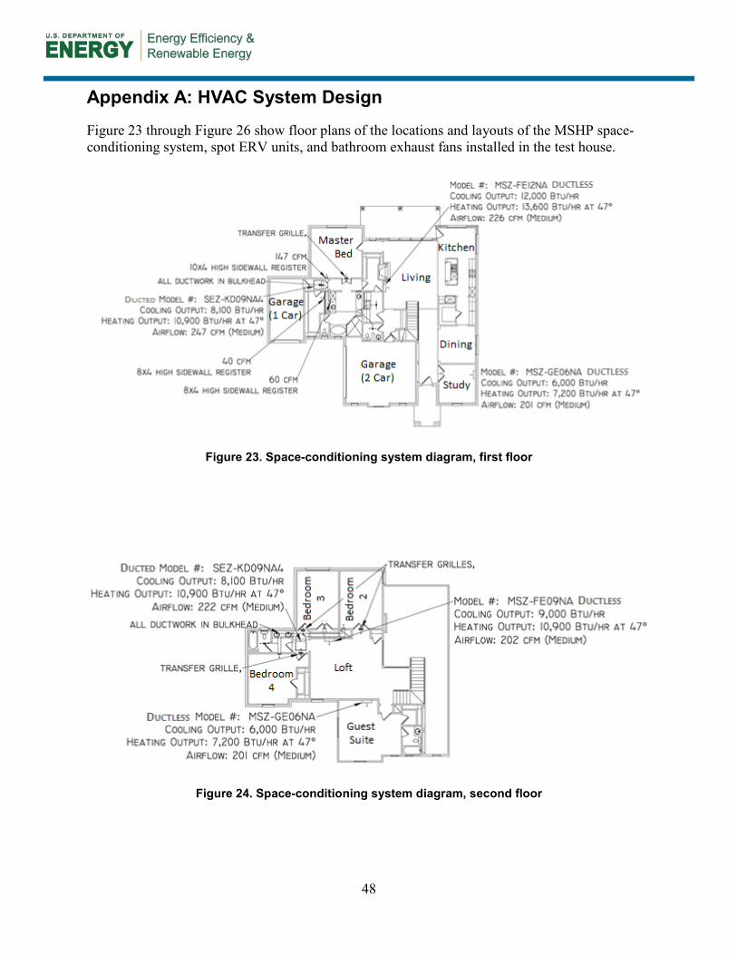
48
Appendix A: HVAC System Design
Figure 23 through Figure 26 show floor plans of the locations and layouts of the MSHP space-conditioning system, spot ERV units, and bathroom exhaust fans installed in the test house.
Figure 23. Space-conditioning system diagram, first floor
Figure 24. Space-conditioning system diagram, second floor
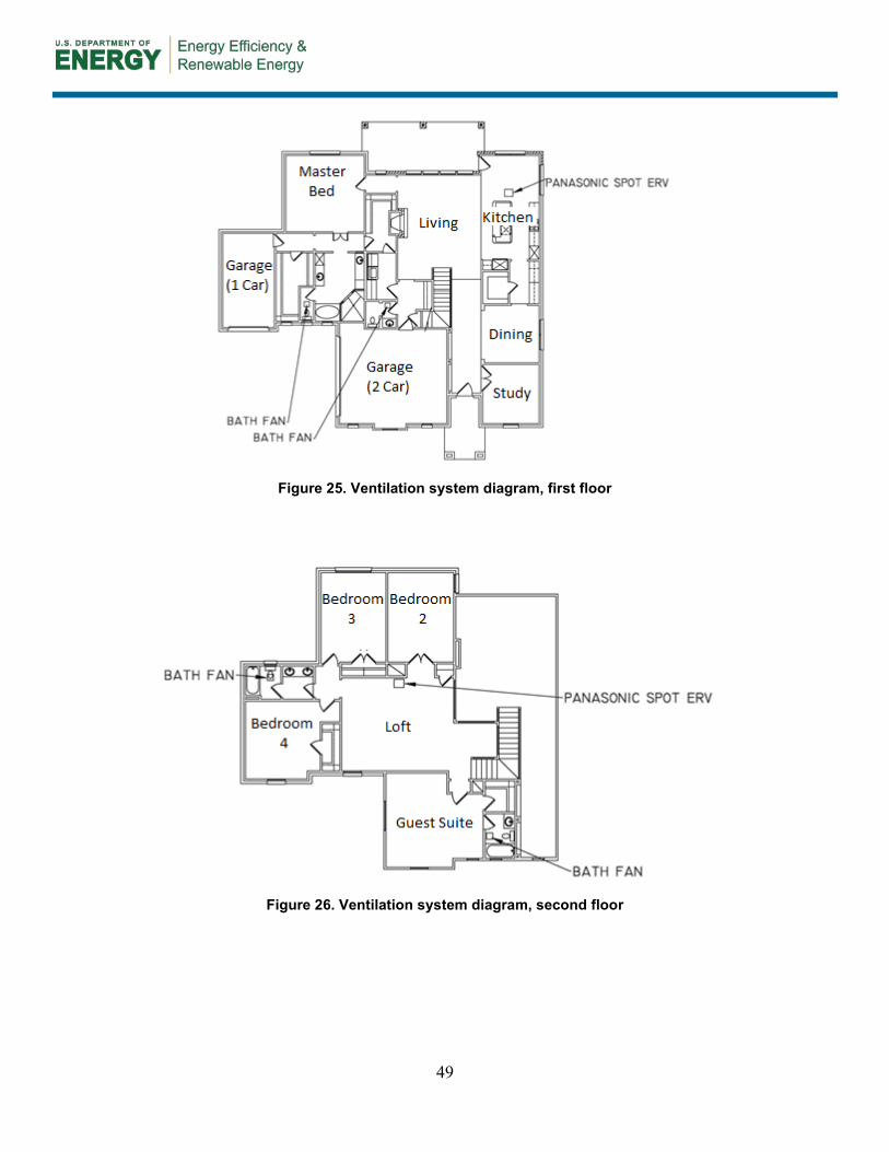
49
Figure 25. Ventilation system diagram, first floor
Figure 26. Ventilation system diagram, second floor

50
Appendix B: Monitoring System Design Diagram
Figure 27 through Figure 29 show the design of the long-term monitoring system, including the sensor locations and the type of data collected from each.
Figure 27. Monitoring system diagram, first floor
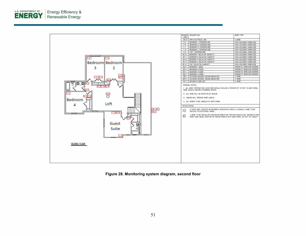
51
Figure 28. Monitoring system diagram, second floor

52
Figure 29. Monitoring system diagram, elevation

DOE/GO-102017-4749 ▪ January 2017
buildingamerica.gov For more information, visit: energy.gov/eere