Ananas : A New Adhoc Network Architectural Scheme
26
HAL Id: inria-00072234 https://hal.inria.fr/inria-00072234 Submitted on 23 May 2006 HAL is a multi-disciplinary open access archive for the deposit and dissemination of sci- entific research documents, whether they are pub- lished or not. The documents may come from teaching and research institutions in France or abroad, or from public or private research centers. L’archive ouverte pluridisciplinaire HAL, est destinée au dépôt et à la diffusion de documents scientifiques de niveau recherche, publiés ou non, émanant des établissements d’enseignement et de recherche français ou étrangers, des laboratoires publics ou privés. Ananas: A New Adhoc Network Architectural Scheme Guillaume Chelius, Éric Fleury To cite this version: Guillaume Chelius, Éric Fleury. Ananas: A New Adhoc Network Architectural Scheme. [Research Report] RR-4354, INRIA. 2002. <inria-00072234>
Transcript of Ananas : A New Adhoc Network Architectural Scheme

HAL Id: inria-00072234https://hal.inria.fr/inria-00072234
Submitted on 23 May 2006
HAL is a multi-disciplinary open accessarchive for the deposit and dissemination of sci-entific research documents, whether they are pub-lished or not. The documents may come fromteaching and research institutions in France orabroad, or from public or private research centers.
L’archive ouverte pluridisciplinaire HAL, estdestinée au dépôt et à la diffusion de documentsscientifiques de niveau recherche, publiés ou non,émanant des établissements d’enseignement et derecherche français ou étrangers, des laboratoirespublics ou privés.
Ananas : A New Adhoc Network Architectural SchemeGuillaume Chelius, Éric Fleury
To cite this version:Guillaume Chelius, Éric Fleury. Ananas : A New Adhoc Network Architectural Scheme. [ResearchReport] RR-4354, INRIA. 2002. <inria-00072234>

ISS
N 0
249-
6399
ISR
N IN
RIA
/RR
--43
63--
FR
+E
NG
ap por t de r ech er ch e
THÈME 1
INSTITUT NATIONAL DE RECHERCHE EN INFORMATIQUE ET EN AUTOMATIQUE
Ananas : A New Adhoc Network ArchitecturalScheme
Guillaume Chelius — Éric Fleury
N° 4354
January 2002

Unité de recherche INRIA Rhône-Alpes655, avenue de l’Europe, 38330 Montbonnot-St-Martin (France)
Téléphone : +33 4 76 61 52 00 — Télécopie +33 4 76 61 52 52
Ananas : A New Adhoc Network Architectural Scheme
Guillaume Chelius�
, Éric Fleury�
Thème 1 — Réseaux et systèmesProjet ARES
Rapport de recherche n° 4354 — January 2002 — 22 pages
Abstract: In this paper, we present a new architecture for adhoc networks : Ananas. Based onthe combined use of a classical adhoc routing protocol and virtual adhoc interfaces, Ananas allows acomplete support for the IP protocol over adhoc networks, including auto-configuration mechanismssuch as the IPv6 one or DHCP. It also provides Internet connectivity and compatibility with Internetservices and protocols such as multicast. Finally Ananas addresses problems of scalability and adhocnetwork partitioning.
Key-words: adhoc networks, network architecture, auto-configuration, routing, communicationnetworks

Ananas : Un nouveau schéma architectural pour réseaux adhoc
Résumé : Nous présentons une nouvelle architecture pour réseaux adhoc : Ananas. Reposant surl’utilisation combinée d’un algorithme de routage adhoc classique et d’interfaces virtuelles, Ananasoffre un support complet du protocole IP sur réseaux adhoc, comprenant les mécanismes d’auto-configuration comme le protocole DHCP ou ceux d’IPv6. Il fournit également une interconnexionavec l’Internet et une compatibilité avec les services et protocoles de l’Internet comme le multicast.Enfin, Ananas résout les problèmes de scalabilité et de partition réseau.
Mots-clés : réseaux adhoc, architecture réseau, auto-configuration, routage, réseaux de communi-cation

Ananas 3
1 Introduction
An adhoc network consists in a set of mobile platforms which own wireless communication devices.In such a raw network, it is not possible to perform advanced networking. Even basic communica-tion schemes are not supported: for example, it is not possible to communicate with nodes out ofrange. There is an obvious need for infrastructures. Since the adhoc network is characterized by theabsence of a wired or wireless but fixed backbone, these infrastructures have to be integrated in themobiles. For infrastructures to be efficient, nodes must cooperate and thus have to organize them-selves according to an architecture. What we call architecture is a set of rules and mechanisms thatallow implantation of services and enable networking. Examples of services are multi-hop routing,multicast and broadcast capabilities, full IP support, auto-configuration or Internet connectivity.
In this paper, we present a new architecture for adhoc networks: Ananas. Based on the combineduse of a classical adhoc routing protocol and virtual adhoc interfaces, Ananas allows a completesupport for the IP protocol over adhoc networks, including auto-configuration mechanisms such asthe IPv6 one or DHCP. It also provides Internet connectivity and compatibility with Internet servicesand protocols such as multicast. Finally Ananas addresses problems of scalability and adhoc networkpartitioning.
The remainder of this paper is organized as follows. Section 2 reviews the different salient char-acteristics that an adhoc network must offer. In this section, we revisit the main features listed inMANet (Mobile Adhoc Networks [2]) and put forward arguments in order to justify a fine grain levelapproach which requires a departure from the actual MANet implementation philosophy. Our pro-posed architecture that meets all listed requirements is presented in section 3. In section 4 severaladvanced features are presented like sub-networking support and auto-configuration. Two repre-sentative adhoc routing protocols (Ad Hoc On-Demand Distance Vector - AODV - as a reactivespecimen and Optimized Link State Routing Protocol - OLSR - for the proactive one) are discussedand a first performance study is proposed. Finally, conclusion and perspectives are presented insection 5.
2 Requests for an adhoc architecture
The fundamental service in an adhoc environment is to allow communication between all mobilesof the network, that is, to able a peer-to-peer mobile routing capability in a purely wireless domainas stated in [2]. One node must be able to reach any other node. Since some nodes may be out ofrange or since some nodes may not share the same medium (uncompatible wireless devices), it isnecessary to define complex routing mechanisms that allow multi-hop routing. Inside a given adhocnetwork, routing mechanisms must be implemented in order to guarantee the intranet connectivity.These mechanisms must ensure unicast, broadcast/multicast and anycast routing capabilities.
2.1 Intranet connectivity
The routing paradigm is the main factor driving the design of all networks. The routing functionproblem in adhoc network may appear as a crucial point and it has been extensively studied this last
RR n° 4354

4 Chelius & Fleury
Hardware level
adhoc level
802.11 channel A
Bluetooth
802.11 channel B
adhoc network
Figure 1: An adhoc network consisting in three physical networks
couple of years. As mentioned in [8], routing in a pure adhoc network raises two main challenges.First of all, traditional solutions proposed in the classical Internet world or in cellular phone networkstry to quickly propagate topology changes. All these solutions are based on the assumption thatthe network is quite stable. This assumption does not necessarily holds for adhoc networks. Thesecond class of assumptions made by classical solutions in the Internet world is that they can rely onsome distributed databases maintained by the operators either in the network node or in specializedmanagement nodes. Once again, in mobile adhoc network this point of view is not feasible anymore.
Thus, specific routing algorithms must be derived for adhoc network and several researches aredone both on proactive and reactive approaches. It is important to notice that, as stated in [2], aMANet node using wireless technologies A and B (e.g. 802.11 and Bluetooth) can communicatewith any other node possessing an interface with technology A or B. This means that the unicastrouting algorithm must operate on a multigraph composed of several physical graph and that anadhoc node is the union of all its interfaces involved in the adhoc network. The unicast routing mustoffer a global connectivity over all the interfaces.
The second important service that must be supported by an adhoc network is the broadcast fa-cility. As in other network, a node may need to send a message to all other nodes. This facilityalso named flooding is used in almost all unicast routing algorithms [7, 10] developed for MANetnetworks and must be supported in a very efficient way at the adhoc level. An adhoc network canalso provide multicast or anycast extensions. This two last services are mandatory in any IPv6 im-plementation. Of course, multicast may be implemented in a trivial way by flooding the networkbut it is not really scalable nor bandwidth efficient! The research challenges for providing multicastare even greater in adhoc network as compared to the Internet mainly due to the intrinsic adhoccharacteristics: lack of infrastructure, high dynamic nature of wireless nodes and their unexpectedmobility. A multicast service should allow group members to join or leave whenever they need and
INRIA

Ananas 5
should not impose any specific assumption on node mobility. It should also provide the managementpart inherent to a multicast session: multicast address group allocation and session advertisement.
2.2 Complete support for TCP/IP
Once the connectivity is provided, the second services that must offer an adhoc network is the TCP/IPone. Indeed, TCP/IP is a de facto standard and the whole Internet rely on these protocols. All appli-cations are developed over this stack. Every node must be able to behave as if it belongs to a standardIP network, that is in ”an interoperable inter-networking capability over a heterogeneous networkinginfrastructure”. Moreover, a partial support or compatibility with IP is also an unsatisfying approach.Base on this trivial remarks, we must focus on the consequences that it implies.
First, IP defines a set of addressing as well as address-related routing rules. For example, it de-fines the notion of IP networks and IP sub-networks. Routing and accessibility directives are associ-ated to these notions. IP also proposes broadcast notions and rules. For example, a packet directedto the address ������� ������� ������������� is received by all nodes connected to the local link of the source andis not supposed to be forwarded. Numerous protocols and applications rely on IP standards. If wedesire a complete compatibility with existing networking environments, the adhoc architecture mustbe fully compatible with IP.
Secondly, several auto-configuration mechanisms are proposed in association to IP. In IPv4, theDHCP protocol allows an host to retrieve its IP address from a server. In IPv6, a node is able toautomatically discover its IP addresses and its routers. If these services are powerful ones in wirednetworks, their importance is even greater in adhoc networks which are, by definition, spontaneous.
2.3 Internet Connectivity
Even if it is only envisioned that MANets will act as “stub” networks, which means that all traffictreated by adhoc nodes is either sourced or sinked within the range of the adhoc network, it is im-portant to offer a global connectivity. This means for example that if auto-configuration is supportedinside an adhoc network (as mentioned in the previous section), a mobile IP node must be able tomove to an adhoc network, perform the mobile IP care of address and continue all its session as itmoved to a classical wired network.
The notion of global connectivity is more general than the care of address feature present inIP mobility. Offering a global connectivity to the Internet is providing a service continuum. Thismeans for example that an adhoc node must be able to receive its favorite net-radio multicasted froma server which is not localized within the adhoc network. As stated above, the multicast protocolused inside the MANet will be specific and the global connectivity service will perform the gatewayoperations with PIM/CBT/YAM...
2.4 Other features
We may want to be able to switch from one physical radio interface to another for power consumptionreason for example, without having to deal with any IP mechanism. It means that micro-mobilitysupport can be implemented inside an adhoc node without changing IP addresses or IP routes.
RR n° 4354

6 Chelius & Fleury
An other very important feature is the easiness of implementation. Turning a node (PC, PDA...)into an adhoc node should not require any kernel modification nor any driver modification.
Last but not least, the scalability requirement may be an important factor. One can imagine thanan adhoc network may support tens to hundreds of mobile nodes but must also be scalable to a higherfactor if this kind of networks becomes really pervasive [6].
2.5 The MANet approach
10.0.0.110.0.0.4
10.0.0.210.0.0.3
MANet node C
MANet node A
MANet node B
Figure 2: A MANet network consisting in three nodes
The MANet group of the IETF -Internet Engineering Task Force - proposes an architecturein which the base element is the MANet node: “a MANet node principally consists of a router,which may be physically attached to multiple IP hosts (or IP-addressable devices), which has poten-tially *multiple* wireless interfaces–each interface using a *different* wireless technology”. Pack-ets travel from nodes to nodes using the IP-level routing mechanism based on IP addresses of MANetnode interfaces. A simple example is given in figure 2. The IP route between node � and node � is������� _ ���� � � �������� � � � ������ � � � �� ������� _ � .
Addressing all the challenges listed in MANet [2] and highlighted in the previous sections mayrequire a departure from solutions available in the literature. Indeed, the actual philosophy is todesign/implement all MANet routing protocols, and more especially unicast ones at the IP level.Yet, it yields to inconsistencies with IP. It results sometimes in endless discussions on the broadcastsemantic in adhoc networks or whether an adhoc network may or not support sub-networking. The
INRIA

Ananas 7
MANet mailing list archive gives evidence of all these non really IP supported features in actualadhoc routing protocols.
3 Our proposal: Ananas
Based on the preceding remarks, it seems important to provide a more fine grain layering that in-cludes an adhoc level as compared to the pure IP layering. We can locate it at level 2.5, i.e., betweenthe level 2 (MAC) and level 3 (IP). Basically, broadcasting a packet to reach all adhoc nodes hasnothing to do with the IP header and the famous TTL field must not be modified while the packettravels inside the range of the adhoc network. In the contrary, locating the adhoc level at layer 2 [1]also have serveral flaws. It makes the handle of multiple interfaces very difficult and hardly enablessupport for micro-mobility.
3.1 Inter-node architecture
Hardware level
adhoc level
IP level
802.11 channel A
Bluetooth
802.11 channel B
adhoc network
adhoc networkabstraction
��������
Switching Hub
Figure 3: The different abstractions in an adhoc network
We propose an architecture breaking up an adhoc network into three levels of abstraction: thehardware level, the adhoc level and the IP level. If the first one relies on a physical reality, interfacecommunication compatibility, the two others are views of mind. The base element of the first levelis the wireless interface whereas for the two others, it is the adhoc node. Our definition of an adhocnode follows the one proposed by MANet in [2].
RR n° 4354

8 Chelius & Fleury
3.1.1 Hardware level
The hardware level is the set of the different hardware networks. A hardware network is the gatheringof all interfaces that are physically able to communicate with each other. At this level, the notion ofcommunication ability is related to wireless device compatibility and not to effective communicationpossibility. Two interfaces belong to the same hardware network if, for example, they both are� ������ � devices emitting on the same channel. Figure 3 shows a configuration where the hardwarelevel is built up with three different hardware networks. The first one is the reunion of
� ��� � �interfaces emitting on channel � , the second one is defined by the Bluetooth technology and the thirdone works on
� ��� � � channel � . In a hardware network, Hardware addresses (e.g. MAC) identifyinterfaces. No routing mechanism is implanted and one hop transmission is the only communicationscheme available. For packet transmission, interfaces are addressed using hardware addresses.
3.1.2 Adhoc level
The adhoc level defines the adhoc network. An adhoc network is the combination of all hardwarenetworks. At this level, the base element is no more the interface but the adhoc node. We do notmake distinction between interfaces but only see nodes with a single interface, the adhoc interfaceconnected to the adhoc network. A unique adhoc device is abstracted from all wireless devices.Figure 3 shows the adhoc level resulting from the previous hardware level. It is composed of allnodes owning an interface present in one of the hardware networks. The connectivity graph is themerging of the three hardware connectivity graphs.
In an adhoc network, an element is named using a unique node identifier, also called an adhocaddress. Multi-hop communication is available. One node may send packets to a node distant fromseveral hops. Packets are commuted from adhoc nodes to adhoc nodes depending on adhoc addressesof destinations. Broadcast and multicast mechanisms are also available. While commuted, a packetmay transit through any underlying hardware network and join the destination by any of its hardwareinterface. The followed path is determined by the commutation or also called routing protocol. Thisrouting protocol is independent of the architecture.
3.1.3 IP level
The IP level is the world as it is seen by level � protocols in the OSI model. As we are mostinterested by IP, we name it the IP level. At this level, an adhoc network is seen as an Ethernetbus: the IP abstracted network. More precisely, it is considered like a switched Ethernet link asillustrated in figure 3. An adhoc node of the adhoc level is looked upon as a single and classicalEthernet interface: the virtual adhoc interface. In other terms, a node with several physical devicesonly owns one interface from the IP view. Nodes are identified by IP addresses and classical IPcommunication is performed. IP packets are emitted and received through virtual adhoc interfacesand transit in the IP abstracted network. All the commutation work performed at the adhoc level istransparent to IP.
This architecture allows a complete compatibility with IP. For example, ����������������������������� packetsreach all nodes of the adhoc network without being IP routed. Auto-configuration becomes straight-
INRIA
Ananas 9
forward. Performing DHCP is possible since adhoc nodes are reachable even if not IP configured.As the commutation is performed at the adhoc level, no IP address is needed to communicate withother adhoc nodes. With IPv6, auto-configuration mechanisms take place as they do on Ethernetlinks. More globally, all the IP world behaves as it does with an Ethernet link. This architecture alsoenables the use of other level 3 protocols on top of the adhoc network.
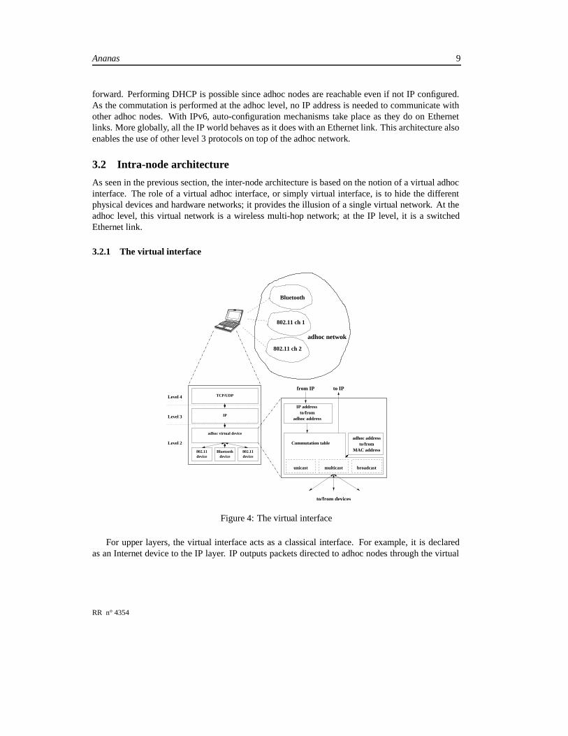
3.2 Intra-node architecture
As seen in the previous section, the inter-node architecture is based on the notion of a virtual adhocinterface. The role of a virtual adhoc interface, or simply virtual interface, is to hide the differentphysical devices and hardware networks; it provides the illusion of a single virtual network. At theadhoc level, this virtual network is a wireless multi-hop network; at the IP level, it is a switchedEthernet link.
3.2.1 The virtual interface
adhoc netwok
Bluetooth
TCP/UDP
IP
adhoc virtual device
802.11 Bluetoothdevice device device
Level 4
Level 3
Level 2 Commutation table
multicastunicast broadcast
to IPfrom IP
to/from devices
802.11 ch 1
802.11 ch 2
802.11
adhoc address
MAC address
adhoc address
IP address to/from
to/from
Figure 4: The virtual interface
For upper layers, the virtual interface acts as a classical interface. For example, it is declaredas an Internet device to the IP layer. IP outputs packets directed to adhoc nodes through the virtual
RR n° 4354

10 Chelius & Fleury
interface. For the under layer, i.e. the link layer, the virtual interface acts as an upper layer protocol.Upon reception of a packet that has transited through the adhoc network, the packet is given to thevirtual interface. This particular architecture is interesting since it does not require any modificationsneither in device drivers nor in the TCP/IP stack.
A virtual interface may or may not handle all network devices of a host. The set of handleddevices is variable and may be modified during run-time. It may be configured automatically ac-cording to a particular policy. For example, the virtual interface may by default handle all wirelessinterfaces. It may also be configured directly by the user which chooses to add or to remove physicaldevices from the virtual interface. A host may also have several virtual interfaces as we will see insection 4.1.2.
3.2.2 Naming adhoc interfaces
0 64328 16
IdHwNet
Id Node Id
Figure 5: Structure of an adhoc address
Hardware type Hardware type value� ������ � 1Bluetooth 2
Table 1: Values of the hardware identifier field
Our approach raises a particular issue related to node identification. To transmit packets fromone adhoc node to another, virtual interfaces need to be addressed. Introducing a logical networkand logical interfaces require the introduction of a corresponding logical naming process. Virtualinterfaces are addressed using adhoc addresses. The structure of an adhoc address is given in figure 5.It has three fields: the net identifier field, Net Id, the hardware identifier field, Hw Id, and thenode identifier field, Node Id.
The net identifier tells which adhoc network the interface is connected to. The default value is . This value has approximately the same semantic as the link local prefix �� � � in the IPv6addressing scheme. It means that no particular network is defined or that the interface is not yetconfigured. We will see in section 4.1.1 how and why this field can take other values. Basically, thenet identifier is used to restrict the set of nodes one may exchange data with. It allows the creationof distinct adhoc networks in the same way it exists distinct IP networks.
The two other fields are filled using one of the physical devices connected to the adhoc network.For each virtual interface, one of its hardware device is picked. The hardware field is filled with thehardware type value of the chosen device. The node identifier is filled with the hardware address
INRIA

Ananas 11
of the chosen device; for example, the MAC address of an Ethernet device or the BD_ADDR of aBluetooth device. Examples of hardware type values are given in table 1. The association of thesetwo fields must ensure the uniqueness of the adhoc address. The � �
-bits size of the hardware field isa suggestion but may be increased to allow the integration of devices with larger hardware addresses.We could also use the EUI-64 format. Since
� ������ � or Bluetooth devices only require � �bits, we
chose this last size.
3.3 Intelligent Commutation
Hop Count Protocol ID Group Sequence / None
Destination adhoc Address
Source adhoc Address
Figure 6: Header of the virtual interface
The role of the virtual interface is to commute packets between different devices and upperlayers protocols. Upon reception of a packet, the interface decides whether it has to emit the packet,through which interface and to which nodes, and whether it has to forward it to upper layers. Wename this process intelligent commutation. It can be seen as a routing operation but since the routingterm commonly references IP routing, we prefer the commutation term.
3.3.1 Commutation support
Destination Next hop Next hopadhoc adhoc interfaceaddress address address ��� � ���� ���� �� � ���� ��� �� ���� ��� ���� � ���� ��� ���� � �� ���� ��� ���� � �� �� � � ��� � �� ��� ��� � �� ��� ���� �� ���� � �� �� � �� � �� ��� ���� �� ��
Table 2: A commutation table
A virtual interface owns a commutation table. This table is managed by a routing protocol suchas the ones studied in the MANet group. Examples are OLSR [7], AODV [10], TBRPF [9] (TopologyBroadcast Based on Reverse-Path Forwarding), DSR [5] (Dynamic Source Routing). The routingprotocol is independent of the global architecture. Any MANet protocol may potentially be used.
RR n° 4354

12 Chelius & Fleury
Its role is to compute or discover routes and to configure commutation tables in adhoc interfaces.Very few work is required to adapt a MANet routing algorithm to our architecture. Basically, nodeidentifiers have to be changed from IP to adhoc addresses. Some protocol control packets must alsobe modified to integrate address translation information. As an example, we present in section 4.2the modifications applied to OLSR and AODV to combine them to our architecture.
An example of commutation table is proposed in table 2. As we can see, commutation rules aredefined using adhoc addresses. Since the destination adhoc address does not figure in the link layerheader, it has to be added in the frame. Some other data have also to be recorded in the packet; anadhoc hop counter for example. These elements are grouped into the virtual interface header. Thisheader is placed in all packets transiting through the adhoc network, between the link layer headerand the upper protocol header, generally the IP header. Its structure is given in figure 6. The twofirst fields are source and destination adhoc addresses. Third field is a hop number and the fourth aprotocol identifier. The fifth field is a packet sequence number only used for broadcast and multicastcommunications. The hop counter is used to limit the range a packet may go. Every time a packet isforwarded by an adhoc node, its hop number is decreased. When reaching , the packet is dropped.
3.3.2 Address translation
Address translation mechanisms are required for the commutation to be effective. As a virtual inter-face internally receives an IP packet, it has to translate an IP address into an adhoc address. To fulfillthis task, every virtual interface owns an IP-to-adhoc address translation table. Filling this table is amechanism deeply bound to the one of creating adhoc routes. To explain how, let us consider a re-active routing algorithm. When node A tries to communicate with node B for which it has no route,a route discovery process is started. In our architecture as in the MANet one, the route request lookslike “I’m looking for a route to the node with IP address ����� ”. Our route resply slightly differs fromthe MANet one. Instead of simply creating the route, it also provides information about adhoc andIP addresses of the destination node. The answer looks like “Here is a route for node with adhoc ad-dress ��� � and IP address ��� � ”. Similar modifications are made in the case of proactive protocols.We will see in section 4.2 how OLSR and AODV are modified to provide address translation.
An adhoc node also requires the correspondence between adhoc addresses and hardware ad-dresses but only for a subset of the adhoc network, its neighbors. This correspondence is extractedfrom control packets of the adhoc routing protocol. The process is similar to the Automatic AddressResolution [9] option of the TBRPF routing protocol. It can be extended to all MANet protocols byconsidering not only Hello control packets but all control packets (e.g. Hello packets for OLSR,Route Request packets for AODV and DSR).
3.3.3 Multi-protocol support
As we have already said, our architecture allows the use of different network protocols over theadhoc network. For all of them, the network is seen as an Ethernet link. Choosing which protocolthe packet is intended for is made by setting the protocol value in the protocol field of the adhocheader. A demultiplexing step in the virtual interface directs the packet toward the correct protocol.A more powerful characteristic of our architecture is to allow an host to use a device simultaneously
INRIA

Ananas 13
Link layer
IP layer
Router protocol
Link layer
Adhoc layer
Router protocol
IP layer
adhoc device
physical device
Device?
IP
adhoc control
adhoc control
Adhoc layerProtoId ?
IP ProtoId ?
adhoc data
Figure 7: Multiplexing and demultiplexing process in an adhoc node
mobile
base station
Range of base station
physical interface
adhoc interface
Figure 8: An hybrid wireless network
in adhoc and in classical modes. Suppose a physical device handled by a virtual adhoc interface isalso configured as an Internet device. From the IP view, the mobile hosts two distinct interfaces.IP networking is performed over these two interfaces without interference. Figure 7 shows themultiplexing and demultiplexing operations performed. When a packet is received from the network,the prototype field of the link layer header indicates whether the packet has to be considered asan adhoc packet or whether it is a classical packet. In the first case, the packet is given to thevirtual interface, in the second case it is given to IP. When IP outputs a packet, it chooses to usethe physical device or the virtual adhoc interface. This mechanism still works with other than IPnetwork protocol; in particular ARP.
RR n° 4354

14 Chelius & Fleury
There are many cases for which this kind of configuration is interesting. Examples are wirelessterminal networks where the access point does not support an adhoc mode though mobiles maysupport it. This is the case of UMTS [4] networks. Communication between the access point and in-range mobiles is performed using the wireless devices of mobiles in a classical way. Communicationbetween mobiles take place on the adhoc network using virtual adhoc interfaces. Communicationbetween the access point and an out-of-range mobile is performed using the adhoc network from themobile to a chosen in-range of the access point node and using the physical interface from this lastnode to the access point. Finding a mobile in range of the access point may be done proactively,with a router advertisement mechanism, or reactively, with a route discovery mechanism. Such aconfiguration is proposed in figure 8.
4 Advanced features and examples
If we confront Ananas to the set of services detailed in section 2, results are completely satisfy-ing. Ananas is an architecture that allows a complete support for IPv4 and IPv6, including auto-configuration mechanisms. It also provides a complete connectivity with the Internet, in regards torouting but also multicast and other services mechanisms. Two points remain: scalability and micro-mobility. The second point is easily handled. Since adhoc nodes are addressed regardless of physicaldevices they host, the commutation process may prefer one physical medium or one hardware net-work, may change routes or may apply a quality of services policy for route selection depending forexample on the power consumption of devices. All changes that may occur in the adhoc commuta-tion process do not introduce any modifications at the IP level. Scalability is harder to achieve. Oneapproach is to use hybrid routing protocols like Zone Routing Protocol [3] which define clusters inan adhoc network. We propose an alternate approach based on the notion of sub-adhoc-networks. Itmay also be used in conjunction with hybrid routing protocols.
4.1 Sub-adhoc-networking
There are several situations for which there is a need to split an adhoc network into several sub-networks - sub-adhoc-networks - that do not interfere with each other. The first one is scalability.Adhoc networks may become huge enough such that routing protocols or services protocols are nomore appropriated. Flooding delay may become too long or commutation tables may explode dueto the huge number of entries. The second reason is to restrict communication. Imagine that everycities of a country host its own adhoc network. A policy may be to limit the adhoc commutationprocess to a single city and to perform IP routing between cities. But in practice, adhoc networks ofdifferent cities may be connected if, for example, there is a high traffic of adhoc cars on a highwaybetween two cities. In this case, there is a need for mechanisms that keep the resulting networksplited into city sub-networks.
INRIA

Ananas 15
Source net Destination Policyidentifier net identifier accept
� accept� � accept� � reject � accept
Table 3: Adhoc nodes communication policy
4.1.1 Ad-hoc network partition
The net identifier field of an adhoc address allows the definition of communication policies betweenadhoc nodes. This field identifies the adhoc network a node belongs to. Basically, two mobiles thatdo not belong to the same network are not allowed to communicate with each other. More precisely,the policy is given in table 3. As already said in section 3.2.2, the default value is . This valueis taken by networks that are not partitioned. This value is also taken by a node that belongs toan adhoc partitioned network but which has not been configured yet. A packet which source hasan network identifier of is always handled by a node. Likewise, a node with a net identifier of always handle an incoming packet. Finally, a node never handles a packet from a source owning adifferent network identifier. Of course, it may be useful to weaken these rules. In the case of controlpackets of routing protocols for example: we may want to know which neighbors we have in anadjacent sub-network and therefore consider Hello packets from this sub-network. A systematicexception to the policy defined in table 3 is the sub-adhoc-network advertisement packetacceptation policy. This packet is studied in the next section.
4.1.2 Auto-configuration
A net identifier may be configured manually. It is set to the default value or to the one of the local sub-adhoc-network the node belongs to. It may also be configured automatically and evolve dependingon the geographical position of the mobile. This auto-configuration mechanism is quite similar to arouter advertisement protocol and is illustrated in figure 9. Some mobiles declare themselves as sub-adhoc-network leaders. They periodically flood the adhoc network with particular control packets:sub-adhoc-network advertisement packets. These packets contain a network identifierchosen by the sub-adhoc-network leader. When an unconfigured mobile receives such a packet, itchanges its adhoc address by setting its network identifier value to the received one. This way, themobile joins the sub-network created by the source of the packet. The membership to a sub-adhoc-network is temporary and refreshed upon reception of advertisement packets. If no packet is receivedduring a delay equal to a fixed time out, the network identifier of the virtual interface is restored tothe default value.
The size of an automatically generated sub-adhoc-network is limited by the adhoc hop valueof the corresponding sub-adhoc-network advertisement packets. This value defines a
RR n° 4354

16 Chelius & Fleury
adhoc network Aentry point
entry pointadhoc network B
adhoc network Aentry point
entry pointadhoc network B
Gateways
adhoc network B abstractionadhoc network A abstractionInternet Internet
from the IP level
adhoc network A adhoc network B
from the adhoc network level
separator nodesflame front
������ ��
���� �� �� ��
� ��
����
Switching Hub ������Switching Hub
Figure 9: Auto-generation of two sub-adhoc-networks
maximal radius around the leader of the sub-network. A second limiting factor is due to overlappingof these extrapolated discs. There is a high probability for nodes to receive several sub-adhoc-network advertisement packets coming from different leaders. To avoid overlapping of sub-adhoc-networks, a flame-front mechanism is used. When a configured mobile, a mobile whichalready belongs to a sub-network, receives a sub-adhoc-network advertisement packet which doesnot correspond to its network identifier, it handles the packet but does not forward it. Instead, itduplicates its virtual interface and configures it with the newly received network identifier. The du-plication process is simple and similar to the process of aliasing an Internet interface. The duplicatedvirtual interface is in all point similar to the first one, handling the same physical devices, except forthe adhoc address which differs in the network identifier field. This mechanism is illustrated infigure 9. If a node with several adhoc devices stops receiving sub-adhoc-network adver-tisement packets for one of its sub-networks, the correspondent virtual interface is not reseted butdestroyed. The flame-front is not always a line as illustrated on the picture. Indeed, race conditionsmay lead to a front of thickness � . It is not a problem since connectivity is still achieved using thecorrect virtual interface.
4.1.3 Interaction with IP
As illustrated in figure 9, different adhoc networks are regarded by IP as different Ethernet links.Since an adhoc interface may only belong to one adhoc network, coherence between adhoc networksand IP representations is achieved. Routing between several adhoc networks is an IP routing taskand mobility between adhoc networks is ensured by Mobile IP [11]. Switching from an adhoc
INRIA

Ananas 17
network to another induces the re-initialization of the adhoc virtual interface. Since IP considersthat the node has moved from one link to another, the interface is also IP reconfigured, includingthe attribution of a new IP address. Keeping connectivity with the old adhoc network is the resultof IP routing between the old and the new adhoc networks. Keeping the old IP address active isperformed by Mobile IP. Moving from one adhoc network to another is similar to the notion ofhandover in wireless telephony. This change is not sudden but includes an intermission duringwhich the adhoc node belongs to both adhoc networks. Duplicating the virtual interface allows thesetup of a soft handover. During this intermission, a node may be addressed on both adhoc networksand, hopefully, may setup the mobile IP protocol without loss of connectivity.
IP routing between adhoc networks may be achieved using wired routes. It may also be per-formed using adhoc bridges. These bridges are established by adhoc nodes that belong to severaladhoc networks, and as a consequence, own several adhoc virtual interfaces. In such a node, allvirtual interfaces are considered by IP. Consequently, the node may act as an IP router between thecorresponding adhoc networks. To install the inter-adhoc network routes in all adhoc nodes, a routeradvertisement mechanism is used. IP routers declare themselves in the adhoc network, precisingwhich networks they have a route for. A simple election mechanism may be used to avoid multiplerouter declarations for a same network.
4.2 Examples of use
As already precised, the Ananas architecture is not bounded to a particular adhoc routing protocol.All protocols proposed by MANet may be adapted to run in coordination with Ananas. Instead ofaccessing the network using the IP stack, they directly access the virtual interface. Other requiredmodifications concern three points. The first one is to replace IP addresses by adhoc addresses whenidentifying nodes. The second is to add the Automatic Address Resolution mechanism.The third consists in filling the translation table between IP and adhoc addresses. In this section, wedescribe how OLSR and AODV may be used as routing protocols in Ananas. We also give someperformance considerations about Ananas.
4.2.1 Use with OLSR
As we can see in figure 10(a), some fields have been omitted in the new version of the Hello packet.They are Interface address fields. With Ananas, these fields are useless. The other modi-fications of the Hello packet deal with address formats. These last modifications have also beenperformed in Topology Change packets but, for this packet, the major change is the addition ofa field. It contains the IP address of the packet source. This field enables all adhoc nodes to extractthe correspondence between the adhoc address of the source and its IP address.
Introducing an Automatic Address Resolution in OLSR is really simple. Every timea node receives a Hello packet, it extracts the source hardware address from the link layer headerand the source adhoc address from the virtual interface header. The correspondence is immediate.
If an adhoc node owns several IP addresses it wants to use, it may declare them to all adhocnodes using Multiple Interface Declaration - MID - packets. OLSR usually uses thispacket to declare several interfaces. Since Ananas nodes only have one virtual interface per adhoc
RR n° 4354

18 Chelius & Fleury
IP address
...IP address
(c) : Multiple Interface Declaration
MSSN ReservedSource IP Address
...
(b) : Topology Change
Multipoint Relay Selector adhoc Address
Multipoint Relay Selector adhoc Address
Reserved #interfaces
...
...
(a) : Hello
Link type Interface # Link Message Size
Link type Interface # Link Message Size
Neighbor adhoc Address
Neighbor adhoc Address
Figure 10: Format of OLSR control packets when used with Ananas
networks, we may use MID packets to declare multiple IP addresses. Modifications are given infigure 10(c).
4.2.2 Use with AODV
As for OLSR, AODV control packet formats have been changed. Route Request and RouteReply packets have been modified to integrate the request source and destination adhoc addressesin addition to their IP ones. The new formats are given in figure 11. The addition of the new fieldsenables the propagation of the adhoc-IP address translation along the created routes.
Hello packets are not mandatory in AODV. Thus, it is not possible to rely on these packets inthe setup of an Automatic Address Resolution. Instead we consider all control packets,including Route Request and Route Reply packets. From these packets, we extract adhocand hardware addresses the same way we do with OLSR. It is interesting to notice that all of ourneighbors do not necessarily emit control packets. We may not have the address translation for all of
INRIA

Ananas 19
Type Reserved Hop CountFlooding ID
Destination Sequence Number
Source Sequence Number
(a) : Route Request
Type Hop CountReservedDestination IP Address
Source IP Address
Source adhoc Address
Destination IP Address
Destination Sequence Number
Source IP Address
Source adhoc Address
Destination adhoc Address
Lifetime
Prefix
(a) : Route Reply
Figure 11: Format of AODV control packets when used with Ananas
our neighbors. Anyway, we only need this translation for neighbors that belong, as a destination oras a relay, to a route we own. For being part of such a route, these nodes have forwarded or answereda Route Request in the past. We do know about their address correspondence.
4.2.3 Performance issues
Using Ananas has a cost. The Ananas header introduces an overhead of 160 bits in all packetstransiting in the adhoc network, reducing the performance the network may achieve. Anyway, thisoverhead is not significant. First, it does not much reduce the volume of data a packet may includes.160 bits is less than � ���
of a� ��� � � link transfer unit (TU: � � � � bytes). Second, this overhead
does not much lower the useful bandwidth of the medium. It only takes � � us to transfer � � bitsover a link with a � � Mbits/s throughput. In the
� ������ � technology, this delay is less than�
times thedelay to wait before accessing the medium (DIFS � � � �����
). Figure 12 presents some theoreticalbandwidth ratios. The medium is a
� ��� � � link with � � Mbits/s throughput. The x-axis is the sizeof data in the exchanged packets. The y-axis is the ratio between the effective bandwidths with andwithout Ananas. The two plots correspond to a classical RTC-CTS-Data-ACK transfer schemeand a Data-ACK one. In the worst case, the overhead is very low, only � � loss of the effectivebandwidth.
RR n° 4354

20 Chelius & Fleury
0.92
0.93
0.94
0.95
0.96
0.97
0.98
0.99
1
0 500 1000 1500 2000
bandwidth_ratio_without_rts(x)bandwidth_ratio_with_rts(x)
Figure 12: Effective bandwidth ratios
Ananas introduces a second overhead when used with some routing protocols. We can see fig-ure 11 that modified AODV packets are larger than classical ones. The overhead is ��� bits in the caseof Route Request packets and � � �
bits for Route Reply packets. Here again, the overheadis not significant and must be relativized. If the AODV payload is larger with Ananas, the packettransitting in the network is not necessarly bigger. Since AODV performs on top of the virtual in-terface, there is no IP nor UDP header in control packets, leading to a lower overhead. The case ofOLSR is slightly different. Indeed, new control packets may be smaller or larger depending on thenumber of neighbors for example. This is due to the fact that adhoc addresses are larger than IPv4ones. Yet, they are smaller than IPv6 ones. If Ananas may introduce overhead in an IPv4 version ofOLSR, it does not with IPv6. It even reduces the volume of control packets in this last case.
If in one hand Ananas means overhead, in the other hand it means fewer control packets. Forexample, Ananas makes no use of ARP and does not exchange ARP packets. Even routing protocolsmay exchange less packets. For example, a host with multiple interfaces do not need to flood thenetwork with Multiple Interface Declaration packets. Some protocols even becomeuseless. Since Ananas allows classical auto-configuration schemes, there is no need for new adhocauto-configuration protocols. Same phenomena with Internet connectivity. As a result, Ananasimproves the performance of the adhoc network, lowering its load. This aspect is not negligiblesince in adhoc networks, the cost of accessing the medium - sending an empty packet - is importantin comparison to the cost of transferring data - linh throughput.
INRIA

Ananas 21
5 Conclusion
In this paper we have presented a new architecture 1 for mobile adhoc network fulfilling all the re-quirements highlighted in the general MANet overview [2]. We justify our architecture by severalarguments that covers intranet connectivity, a complete support for TCP/IP and an Internet connec-tivity. The result of this work is an architecture that can be completely integrated in the Internet.Ananas defines an adhoc network by introducing three levels of abstraction: the hardware level, theadhoc level and the IP level. Based on this architecture, actual adhoc routing protocols can be im-plemented and advanced feature like sub-networking or auto-configuration can be offered. We thusprovide an unification of architecture between Internet and adhoc networks. Moreover, the overheadintroduced is really low. Ananas even lowers the number of packets transiting across the network.
As stated before, several possible extensions for this work are open to investigation. The first oneconcerns the implementation of the first version of our architecture under linux and windows. Mainopen researches concern the unification of services over this unified architecture. We strongly needservices continuity. Indeed, it is the only way to effectively integrate adhoc networks in the Internet.It is also necessary for performance considerations. This service continuity includes Multicast, QoS,SLP...
A second domain of extension concerns issues other than routing and has received much lessattention so far. Since we can dynamically modify the network topology by creating, destroyingand/or merging sub-adhoc-networks, there is an open door for many optimization problems. How tocreate the most efficient topologies: to lower interferences between areas, to lower the sub-networkloads? There are also direct applications with the Bluetooth technology or with frequency hoppingthat we are currently evaluating. More generally, purely distributed algorithm dedicated to adhocnetworks represent a promising research field.
References
[1] Lunar. http://www.docs.uu.se/selnet/lunar/.
[2] S. Corson and J. Macker. Mobile ad hoc networking (MANET): Routing protocol performanceissues and evaluation considerations. IETF RFC 2501, January 1999.
[3] Z. Haas and M. Pearlman. Providing ad-hoc connectivity with the reconfigurable wirelessnetworks. In Proceedings of the ACM SIGCOMM ’98, September 1998.
[4] H. Holma and A. Toskala, editors. WCDMA for UMTS. Wiley, 2001.
[5] Y. Hu, J. Jetcheva, D. Johnson, and D. Maltz. The dynamic source routing protocol for mobilead hoc networks (DSR). Internet Draft (work in progress), November 2001.
[6] J.-P. Hubaux, Th. Gross, J.-Y. Le Boudec, and M. Vetterly. Towards self-organized mobilead hoc networks : the terminode project. IEEE Communications Magazine - Special Issue onTelecomuunications Networking at the Start of the 21st Century, January 2001.
1Sources available at http://citi.insa-lyon.fr/download/
RR n° 4354
22 Chelius & Fleury
[7] P. Jacquet, P. Muhlethaler, A. Qayyum, A. Laouiti, L. Viennot, and T. Clausen. Optimized linkstate routing protocol. Internet Draft (work in progress), October 2001.
[8] D. Maltz, J. Broch, J. Jetcheva, and D. Johnson. The effect of on-demande behavior in routingprotocols for multi-hop wireless networks. IEEE JSAC, August 1999.
[9] R. Ogier, F. Templin, B. Bellur, and M. Lewis. Topology broadcast based on reverse-pathforwarding (tbrpf). Internet Draft (work in progress), November 2001.
[10] C. Perkins, E. Royer, and S. Das. Ad hoc on-demand distance vector (AODV) routing. InternetDraft (work in progress), November 2001.
[11] J. Solomon. Mobile IP. Prentice Hall, 1998.
INRIA

Unité de recherche INRIA Rhône-Alpes655, avenue de l’Europe - 38330 Montbonnot-St-Martin (France)
Unité de recherche INRIA Lorraine : LORIA, Technopôle de Nancy-Brabois - Campus scientifique615, rue du Jardin Botanique - BP 101 - 54602 Villers-lès-Nancy Cedex (France)
Unité de recherche INRIA Rennes : IRISA, Campus universitaire de Beaulieu - 35042 Rennes Cedex (France)Unité de recherche INRIA Rocquencourt : Domaine de Voluceau - Rocquencourt - BP 105 - 78153 Le Chesnay Cedex (France)
Unité de recherche INRIA Sophia Antipolis : 2004, route des Lucioles - BP 93 - 06902 Sophia Antipolis Cedex (France)
ÉditeurINRIA - Domaine de Voluceau - Rocquencourt, BP 105 - 78153 Le Chesnay Cedex (France)
http://www.inria.frISSN 0249-6399