Analyzing Air Handling Unit Efficiency - Onset · PDF file5 Analyzing Air Handling Unit...
24
Analyzing Air Handling Unit Efficiency Michael Rosenberg, PE, CEM
-
Upload
truongdieu -
Category
Documents
-
view
218 -
download
0
Transcript of Analyzing Air Handling Unit Efficiency - Onset · PDF file5 Analyzing Air Handling Unit...
Analyzing Air Handling Unit EfficiencyMichael Rosenberg, PE, CEM

www.onsetcomp.com
onset®
Analyzing Air Handling Unit Efficiency
onset®
Analyzing Air Handling Unit Efficiency
Introduction....................................................................................................................................1
Air Handlers and Energy...............................................................................................................2
Air Handler Case Study.................................................................................................................7
Optimizing Economization Conditions...........................................................................................8
Mixed Air Temperature Control....................................................................................................10
Carbon Dioxide Control................................................................................................................11
Discharge Air and Pre-heat Temperature Control.......................................................................12
Zone temperature Control...........................................................................................................14
Supply Fan Speed Control..........................................................................................................15
Return/Relief Fan Speed Control................................................................................................16
Calibration, Commissioning, and Balancing................................................................................17
References....................................................................................................................................19
Analyzing Air Handling Unit Efficiency1-800-LOGGERS
1 Analyzing Air Handling Unit Efficiency www.onsetcomp.com
onset®
IntroductionOperating a heating, ventilation and air conditioning (HVAC) system at optimum efficiency in a commercial setting is complicated, to say the least. There is a very real chance that any number of setpoints, levels and feedbacks at boilers, chillers, pumps, fans, air delivery components, and more can cause costly inefficiencies.
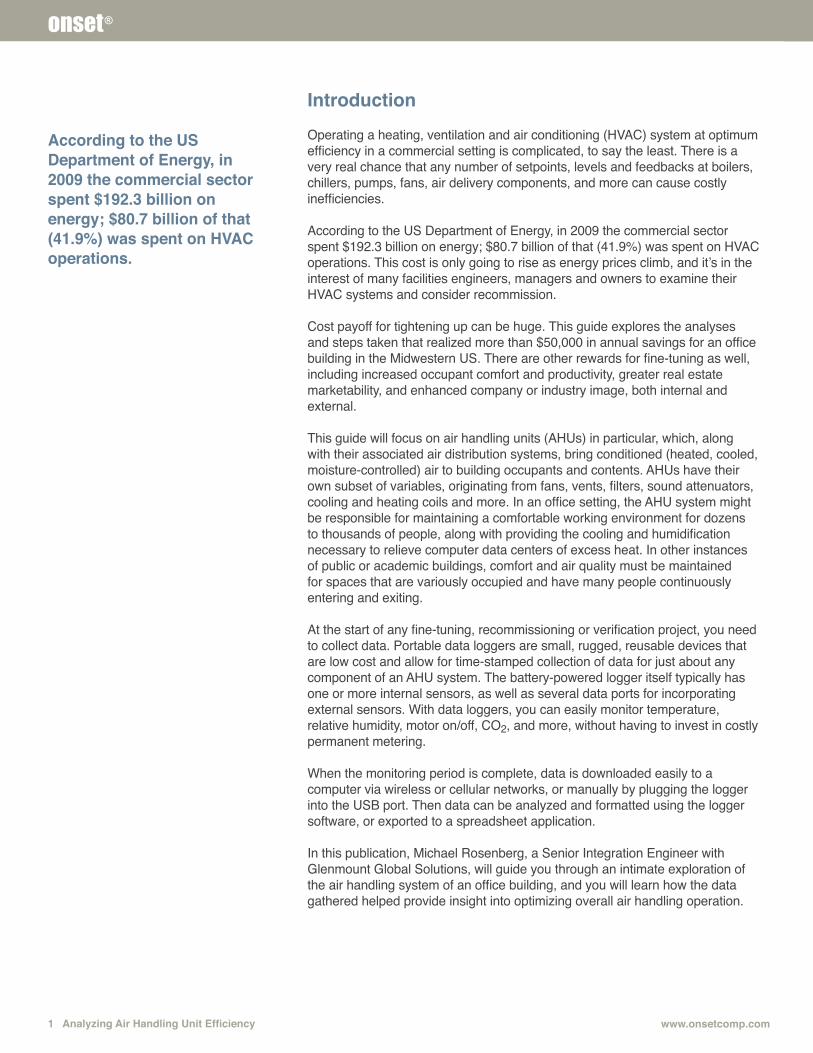
According to the US Department of Energy, in 2009 the commercial sector spent $192.3 billion on energy; $80.7 billion of that (41.9%) was spent on HVAC operations. This cost is only going to rise as energy prices climb, and it’s in the interest of many facilities engineers, managers and owners to examine their HVAC systems and consider recommission.
Cost payoff for tightening up can be huge. This guide explores the analyses and steps taken that realized more than $50,000 in annual savings for an office building in the Midwestern US. There are other rewards for fine-tuning as well, including increased occupant comfort and productivity, greater real estate marketability, and enhanced company or industry image, both internal and external.
This guide will focus on air handling units (AHUs) in particular, which, along with their associated air distribution systems, bring conditioned (heated, cooled, moisture-controlled) air to building occupants and contents. AHUs have their own subset of variables, originating from fans, vents, filters, sound attenuators, cooling and heating coils and more. In an office setting, the AHU system might be responsible for maintaining a comfortable working environment for dozens to thousands of people, along with providing the cooling and humidification necessary to relieve computer data centers of excess heat. In other instances of public or academic buildings, comfort and air quality must be maintained for spaces that are variously occupied and have many people continuously entering and exiting.
At the start of any fine-tuning, recommissioning or verification project, you need to collect data. Portable data loggers are small, rugged, reusable devices that are low cost and allow for time-stamped collection of data for just about any component of an AHU system. The battery-powered logger itself typically has one or more internal sensors, as well as several data ports for incorporating external sensors. With data loggers, you can easily monitor temperature, relative humidity, motor on/off, CO2, and more, without having to invest in costly permanent metering. When the monitoring period is complete, data is downloaded easily to a computer via wireless or cellular networks, or manually by plugging the logger into the USB port. Then data can be analyzed and formatted using the logger software, or exported to a spreadsheet application.
In this publication, Michael Rosenberg, a Senior Integration Engineer with Glenmount Global Solutions, will guide you through an intimate exploration of the air handling system of an office building, and you will learn how the data gathered helped provide insight into optimizing overall air handling operation.
According to the US Department of Energy, in 2009 the commercial sector spent $192.3 billion on energy; $80.7 billion of that (41.9%) was spent on HVAC operations.
onset®
Analyzing Air Handling Unit Efficiency 21-800-LOGGERS
onset®
Air Handlers and EnergyAir handling units are components in a mechanical system used to condition and circulate air as part of a heating, ventilating and air conditioning (HVAC) system. An air handler typically contains a fan, heating coils, cooling coils, a filter section, sound attenuators, dampers, actuators and controls, depending on the particular design. Air handlers are usually connected to a system of ductwork that distributes the conditioned air through the building. The intake side of the AHU typically has a return path for the air to be re-conditioned and mixed with outside air. Several types of air handler designs are available, including variable air volume, dual duct (hot deck/cold deck), multi-zone, and make-up air units that provide 100% outdoor air. The basic design type reviewed in this best practices guide is a variable volume AHU.
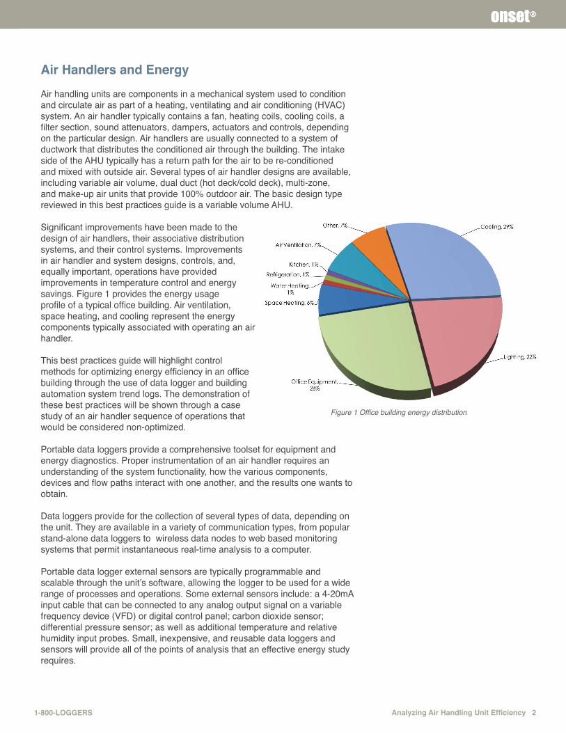
Significant improvements have been made to the design of air handlers, their associative distribution systems, and their control systems. Improvements in air handler and system designs, controls, and, equally important, operations have provided improvements in temperature control and energy savings. Figure 1 provides the energy usage profile of a typical office building. Air ventilation, space heating, and cooling represent the energy components typically associated with operating an air handler.
This best practices guide will highlight control methods for optimizing energy efficiency in an office building through the use of data logger and building automation system trend logs. The demonstration of these best practices will be shown through a case study of an air handler sequence of operations that would be considered non-optimized.
Portable data loggers provide a comprehensive toolset for equipment and energy diagnostics. Proper instrumentation of an air handler requires an understanding of the system functionality, how the various components, devices and flow paths interact with one another, and the results one wants to obtain.
Data loggers provide for the collection of several types of data, depending on the unit. They are available in a variety of communication types, from popular stand-alone data loggers to wireless data nodes to web based monitoring systems that permit instantaneous real-time analysis to a computer.
Portable data logger external sensors are typically programmable and scalable through the unit’s software, allowing the logger to be used for a wide range of processes and operations. Some external sensors include: a 4-20mA input cable that can be connected to any analog output signal on a variable frequency device (VFD) or digital control panel; carbon dioxide sensor; differential pressure sensor; as well as additional temperature and relative humidity input probes. Small, inexpensive, and reusable data loggers and sensors will provide all of the points of analysis that an effective energy study requires.
Figure 1 Office building energy distribution
3 Analyzing Air Handling Unit Efficiency www.onsetcomp.com
onset®
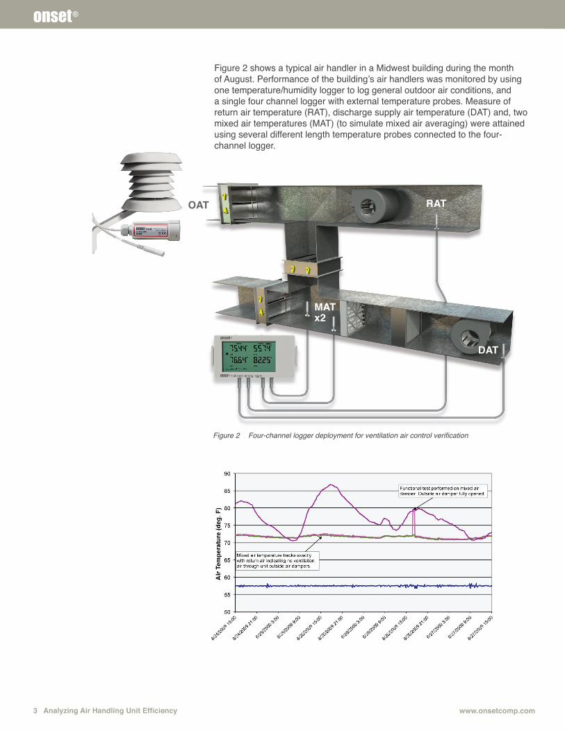
Figure 2 shows a typical air handler in a Midwest building during the month of August. Performance of the building’s air handlers was monitored by using one temperature/humidity logger to log general outdoor air conditions, and a single four channel logger with external temperature probes. Measure of return air temperature (RAT), discharge supply air temperature (DAT) and, two mixed air temperatures (MAT) (to simulate mixed air averaging) were attained using several different length temperature probes connected to the four-channel logger.
Figure 2 Four-channel logger deployment for ventilation air control verification
OAT
MATx2
DAT
RAT
Analyzing Air Handling Unit Efficiency 41-800-LOGGERS
onset®
The value of using the four-channel loggers along with the low-cost temperature probes is that it saved money, as individual loggers in each independent airstream would have been expensive. There is also value in the time-saving benefit of multi-channel loggers as they enable a single setup and a single data offload.
Two of the challenges of effective equipment benchmarking and energy analysis are the period of analysis and the season of the trending period. For example, the building in this case study was evaluated during the winter period. Based on that data, it was possible to ascertain some potential cooling-related operations without actually providing trends during the cooling season. The trends in the previous figures were from the strictly cooling mode of operation, without any economizer operation.
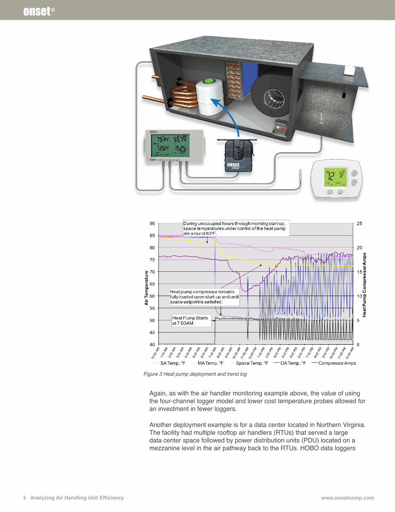
In another building located in Glendale, CA, portable data loggers were used extensively to analyze the operations of approximately 400 water source heat pumps. This building was operating an older DOS-based automation system with very limited trending capability. In pursuit of LEED certification, the energy team turned to portable data loggers to analyze the operations of their heat pumps and make decisions on how the new automation system would be used to improve energy efficiency. The deployment strategy here was similar to the previous example. Several heat pumps were instrumented with four-channel loggers placed in the ceiling plenum near the unit. A temperature probe was directed through the ceiling and toward the heat pump’s thermostat for space temperature monitoring. One probe was placed in the discharge air side of the heat pump and one in the rear of the heat pump where duct outside air mixes with plenum/return air for reconditioning. The final input was connected to an external amperage probe to measure the load on the heat pump’s compressor as it cycles through its cooling mode. An additional temperature and relative humidity logger was placed on the roof in a sheltered area to obtain a reference of outdoor air ambient conditions during the trending period.
5 Analyzing Air Handling Unit Efficiency www.onsetcomp.com
onset®
Again, as with the air handler monitoring example above, the value of using the four-channel logger model and lower cost temperature probes allowed for an investment in fewer loggers.
Another deployment example is for a data center located in Northern Virginia. The facility had multiple rooftop air handlers (RTUs) that served a large data center space followed by power distribution units (PDU) located on a mezzanine level in the air pathway back to the RTUs. HOBO data loggers
Figure 3 Heat pump deployment and trend log
Analyzing Air Handling Unit Efficiency 61-800-LOGGERS
onset®
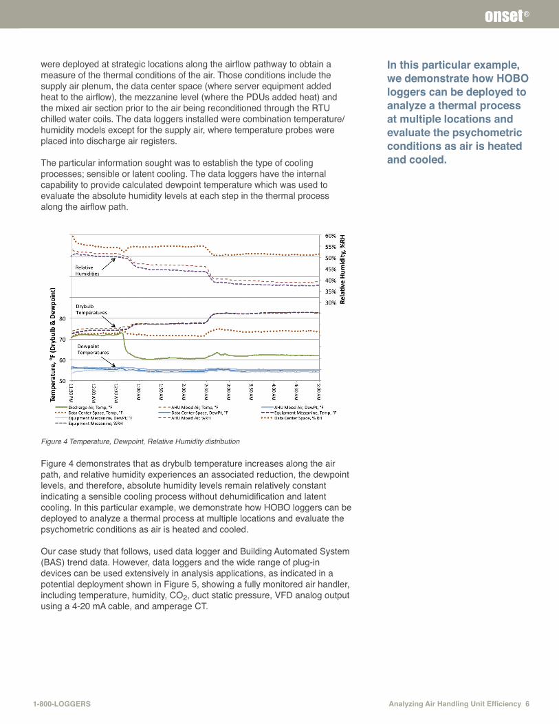
were deployed at strategic locations along the airflow pathway to obtain a measure of the thermal conditions of the air. Those conditions include the supply air plenum, the data center space (where server equipment added heat to the airflow), the mezzanine level (where the PDUs added heat) and the mixed air section prior to the air being reconditioned through the RTU chilled water coils. The data loggers installed were combination temperature/ humidity models except for the supply air, where temperature probes were placed into discharge air registers.
The particular information sought was to establish the type of cooling processes; sensible or latent cooling. The data loggers have the internal capability to provide calculated dewpoint temperature which was used to evaluate the absolute humidity levels at each step in the thermal process along the airflow path.
Figure 4 Temperature, Dewpoint, Relative Humidity distribution
Figure 4 demonstrates that as drybulb temperature increases along the air path, and relative humidity experiences an associated reduction, the dewpoint levels, and therefore, absolute humidity levels remain relatively constant indicating a sensible cooling process without dehumidification and latent cooling. In this particular example, we demonstrate how HOBO loggers can be deployed to analyze a thermal process at multiple locations and evaluate the psychometric conditions as air is heated and cooled.
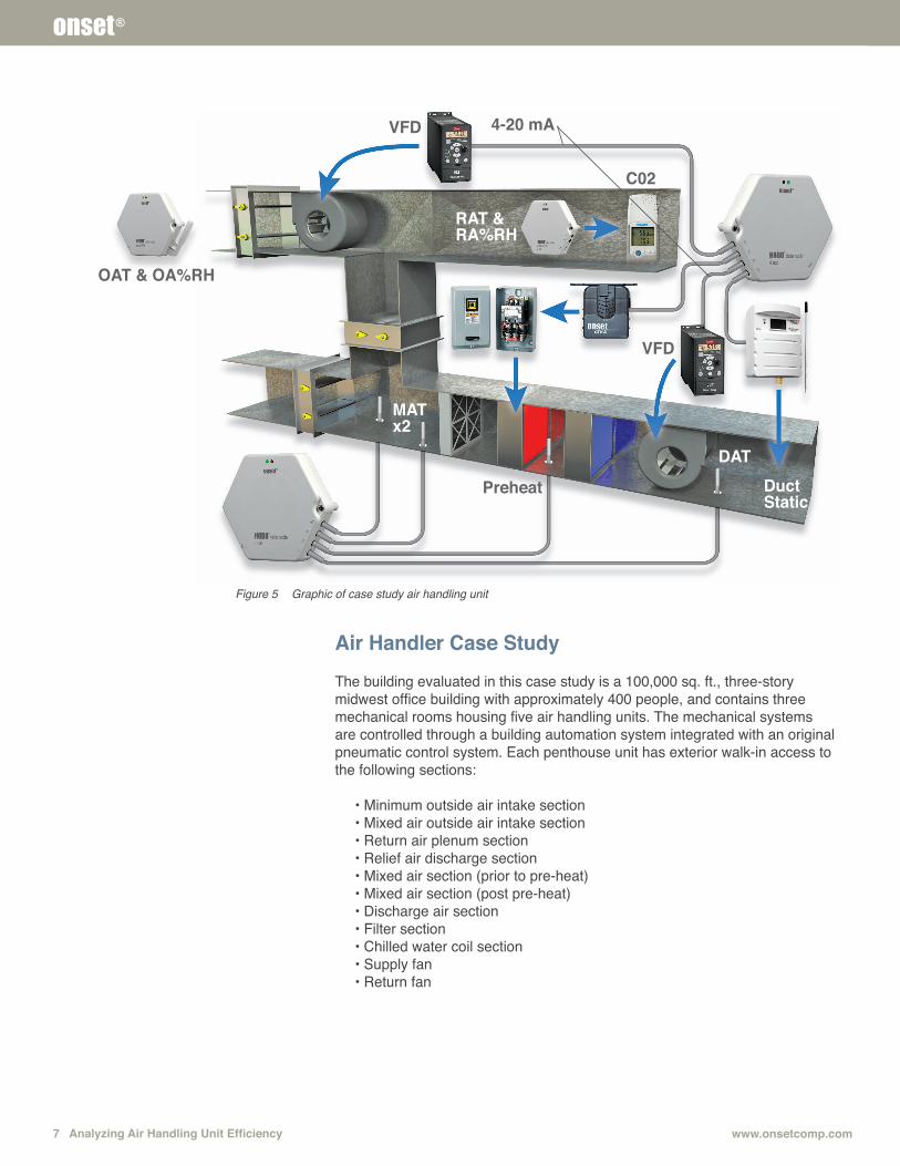
Our case study that follows, used data logger and Building Automated System (BAS) trend data. However, data loggers and the wide range of plug-in devices can be used extensively in analysis applications, as indicated in a potential deployment shown in Figure 5, showing a fully monitored air handler, including temperature, humidity, CO2, duct static pressure, VFD analog output using a 4-20 mA cable, and amperage CT.
In this particular example, we demonstrate how HOBO loggers can be deployed to analyze a thermal process at multiple locations and evaluate the psychometric conditions as air is heated and cooled.
7 Analyzing Air Handling Unit Efficiency www.onsetcomp.com
onset®
Air Handler Case StudyThe building evaluated in this case study is a 100,000 sq. ft., three-story midwest office building with approximately 400 people, and contains three mechanical rooms housing five air handling units. The mechanical systems are controlled through a building automation system integrated with an original pneumatic control system. Each penthouse unit has exterior walk-in access to the following sections:
• Minimum outside air intake section• Mixed air outside air intake section• Return air plenum section• Relief air discharge section• Mixed air section (prior to pre-heat)• Mixed air section (post pre-heat)• Discharge air section• Filter section• Chilled water coil section• Supply fan• Return fan
OAT & OA%RH
C02
VFD
VFD
4-20 mA
Preheat DuctStatic
DAT
MAT x2
RAT & RA%RH
Figure 5 Graphic of case study air handling unit
Analyzing Air Handling Unit Efficiency 81-800-LOGGERS
onset®
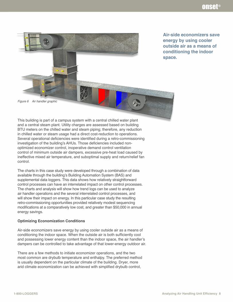
Figure 6 Air handler graphic
This building is part of a campus system with a central chilled water plant and a central steam plant. Utility charges are assessed based on building BTU meters on the chilled water and steam piping; therefore, any reduction in chilled water or steam usage had a direct cost-reduction to operations. Several operational deficiencies were identified during a retro-commissioning investigation of the building’s AHUs. Those deficiencies included non-optimized economizer control, inoperative demand control ventilation control of minimum outside air dampers, excessive pre-heat load caused by ineffective mixed air temperature, and suboptimal supply and return/relief fan control. The charts in this case study were developed through a combination of data available through the building’s Building Automation System (BAS) and supplemental data loggers. This data shows how relatively straightforward control processes can have an interrelated impact on other control processes. The charts and analysis will show how trend logs can be used to analyze air handler operations and the several interrelated control processes, and will show their impact on energy. In this particular case study the resulting retro-commissioning opportunities provided relatively modest sequencing modifications at a comparatively low cost, and greater than $50,000 in annual energy savings.
Optimizing Economization Conditions
Air-side economizers save energy by using cooler outside air as a means of conditioning the indoor space. When the outside air is both sufficiently cool and possessing lower energy content than the indoor space, the air handler’s dampers can be controlled to take advantage of that lower-energy outdoor air.
There are a few methods to initiate economizer operations, and the two most common are drybulb temperature and enthalpy. The preferred method is usually dependent on the particular climate of the building. Dryer, more arid climate economization can be achieved with simplified drybulb control,
Air-side economizers save energy by using cooler outside air as a means of conditioning the indoor space.
9 Analyzing Air Handling Unit Efficiency www.onsetcomp.com
onset®
whereas more humid climates are best served by using enthalpy control. Between those two methods, the conditions that initiate economization can sometimes be based on a comparison between outdoor air and interior conditions, or based on a fixed outdoor air condition. The control system that was investigated provided two settings to initiate the economizer sequence: drybulb temperature and enthalpy. The drybulb economizer enable was based on a fixed outside air temperature of 55°F, and the enthalpy economizer enable was based on a fixed outside air enthalpy of 23 Btu/lb. Through various functional tests it was determined that the economizer control was based on outside air dry bulb temperature only, and that the enthalpy capability was not active.
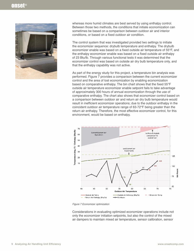
As part of the energy study for this project, a temperature bin analysis was performed. Figure 7 provides a comparison between the current economizer control and the area of lost economization by enabling economization based on comparative enthalpy. The bin chart shows that the fixed 55°F outside air temperature economizer enable setpoint fails to take advantage of approximately 300 hours of annual economization through the use of comparative enthalpy. The chart also shows that economizer control based on a comparison between outdoor air and return air dry bulb temperature would result in inefficient economizer operations; due to the outdoor enthalpy in the coincident outdoor air temperature range of 63-72°F being greater than the return air enthalpy. Therefore, the most effective economizer control, for this environment, would be based on enthalpy.
Figure 7 Economizer optimization
Considerations in evaluating optimized economizer operations include not only the economizer initiation setpoints, but also the control of the mixed air dampers to maintain mixed air temperature, sensor calibration, sensor
Analyzing Air Handling Unit Efficiency 101-800-LOGGERS
onset®
placement, and balancing the economizer thermal savings with the relief fan power, economizer lockouts and unintended heating loads. Considerations toward dewpoint temperature of the airstream and temperature of the chilled water coil are also important. Economizer control can be a complex study of psychometrics that is outside of the scope of this guide. Portable data loggers provide the tools necessary to evaluate effective economizer operations.
Best Practice Tip:1. Optimize the economizer control based on the environment.
In areas where moisture levels in the air are prevalent, use an enthalpy type control. Dryer environments can be achieved with drybulb.
2. The effects of inefficient economizer, mixed air damper and minimum outside air control have clear impacts on cooling and heating. The case study also demonstrates fan power issues associated with outside air damper control, showing a correlation to relief fan speed and power consumption.
3. Maintain an outside air limit on economization. Excessive ventilation air can result in excessive relief fan energy and filter usage. Using a direct comparison of enthalpy may not always be the most economical. With regard to the case study, the recommended programming modification is to include an enthalpy comparison and raise the dry bulb limit setpoint from 55ºF outside air temperature to 65ºF.
4. Sensor calibration and placement can be the number-one issue affecting effective economizer control. Regularly calibrate the critical process-related BAS system sensors for effective economization.
Mixed Air Temperature Control
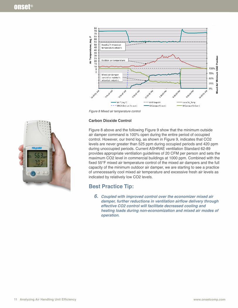
Mixed air temperature control is intended to supplement economizer control by adjusting the proportion of outside air with building return air as outside air conditions get colder, providing a means to exit economizer control. Figure 8 shows the economizer mixed air damper controlling to maintain a 55°F mixed air temperature setpoint. During this period of trending the outdoor air temperature ranged between 10°F and 30°F. The objective of using a 55°F mixed air temperature setpoint is to provide cooler air for cooling space with internal heat gains, while other zones are provided heat through local variable air volume (VAV) reheat control. We will see through further review of this case study how that temperature control philosophy actually increases energy consumption.
Best Practice Tip:5. The preferred method of control for the mixed air dampers is
based on an adjustable mixed air temperature setpoint that should track with the discharge air temperature setpoint.
Portable data loggers provide the tools necessary to evaluate effective economizer operations.
11 Analyzing Air Handling Unit Efficiency www.onsetcomp.com
onset®
Figure 8 Mixed air temperature control
Carbon Dioxide Control
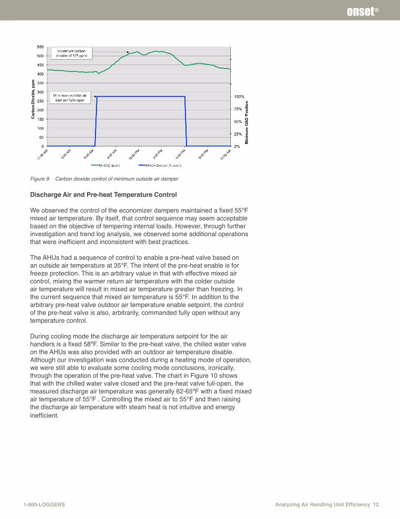
Figure 8 above and the following Figure 9 show that the minimum outside air damper command is 100% open during the entire period of occupied control. However, our trend log, as shown in Figure 9, indicates that CO2 levels are never greater than 525 ppm during occupied periods and 420 ppm during unoccupied periods. Current ASHRAE ventilation Standard 62-89 provides appropriate ventilation guidelines of 20 CFM per person and sets the maximum CO2 level in commercial buildings at 1000 ppm. Combined with the fixed 55°F mixed air temperature control of the mixed air dampers and the full capacity of the minimum outdoor air damper, we are starting to see a practice of unnecessarily cool mixed air temperature and excessive fresh air levels as indicated by relatively low CO2 levels.
Best Practice Tip:6. Coupled with improved control over the economizer mixed air
damper, further reductions in ventilation airflow delivery through effective CO2 control will facilitate decreased cooling and heating loads during non-economization and mixed air modes of operation.
Analyzing Air Handling Unit Efficiency 121-800-LOGGERS
onset®
Figure 9 Carbon dioxide control of minimum outside air damper
Discharge Air and Pre-heat Temperature Control
We observed the control of the economizer dampers maintained a fixed 55°F mixed air temperature. By itself, that control sequence may seem acceptable based on the objective of tempering internal loads. However, through further investigation and trend log analysis, we observed some additional operations that were inefficient and inconsistent with best practices.
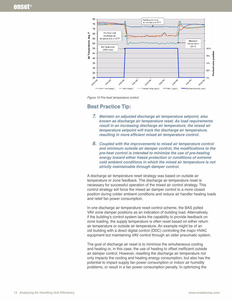
The AHUs had a sequence of control to enable a pre-heat valve based on an outside air temperature at 35°F. The intent of the pre-heat enable is for freeze protection. This is an arbitrary value in that with effective mixed air control, mixing the warmer return air temperature with the colder outside air temperature will result in mixed air temperature greater than freezing. In the current sequence that mixed air temperature is 55°F. In addition to the arbitrary pre-heat valve outdoor air temperature enable setpoint, the control of the pre-heat valve is also, arbitrarily, commanded fully open without any temperature control. During cooling mode the discharge air temperature setpoint for the air handlers is a fixed 58ºF. Similar to the pre-heat valve, the chilled water valve on the AHUs was also provided with an outdoor air temperature disable. Although our investigation was conducted during a heating mode of operation, we were still able to evaluate some cooling mode conclusions, ironically, through the operation of the pre-heat valve. The chart in Figure 10 shows that with the chilled water valve closed and the pre-heat valve full-open, the measured discharge air temperature was generally 62-65ºF with a fixed mixed air temperature of 55°F . Controlling the mixed air to 55°F and then raising the discharge air temperature with steam heat is not intuitive and energy inefficient.
13 Analyzing Air Handling Unit Efficiency www.onsetcomp.com
onset®
Figure 10 Pre-heat temperature control
Best Practice Tip:7. Maintain an adjusted discharge air temperature setpoint, also
known as discharge air temperature reset. As load requirements result in an increasing discharge air temperature, the mixed air temperature setpoint will track the discharge air temperature, resulting in more efficient mixed air temperature control.
8. Coupled with the improvements to mixed air temperature control and minimum outside air damper control, the modifications to the pre-heat control is intended to minimize the use of pre-heating energy toward either freeze protection or conditions of extreme cold ambient conditions in which the mixed air temperature is not strictly maintainable through damper control.
A discharge air temperature reset strategy was based on outside air temperature or zone feedback. The discharge air temperature reset is necessary for successful operation of the mixed air control strategy. This control strategy will force the mixed air damper control to a more closed position during colder ambient conditions and reduce air handler heating loads and relief fan power consumption.
In one discharge air temperature reset control scheme, the BAS polled VAV zone damper positions as an indication of building load. Alternatively, if the building’s control system lacks the capability to provide feedback on zone loading, the supply temperature is often reset based on either return air temperature or outside air temperature. An example might be of an old building with a direct digital control (DDC) controlling the major HVAC equipment but maintaining VAV control through an older pneumatic system.
The goal of discharge air reset is to minimize the simultaneous cooling and heating or, in this case, the use of heating to offset inefficient outside air damper control. However, resetting the discharge air temperature not only impacts the cooling and heating energy consumption, but also has the potential to impact supply fan power consumption or indoor air humidity problems, or result in a fan power consumption penalty. In optimizing the
Analyzing Air Handling Unit Efficiency 141-800-LOGGERS
onset®
discharge air temperature reset logic consideration toward minimizing the overall heating energy, cooling energy and fan power consumption must be evaluated.
Zone Temperature Control
The zone thermostats for this case study provided tenants with local temperature override capability. The typical zone temperature setpoint on the thermostats was 72°F. However, the zones were provided the ability to adjust the local temperature by +/- 5.0°F. With full local adjustment at the thermostats, the maximum cooling setpoint places an excessive cooling load on the system and forces the air handling unit to work harder to maintain duct static pressure. On the heating side, the effective temperature setpoint risked the greater energy usage through the VAV hot water reheat valves. The wide range of control over the zone thermostats makes effective control of the air handling units difficult to maintain.
An extremely important point with regards to VAV operations is that VAVs are, essentially, part of the air handling system. Inefficiencies in the operation of VAVs can impact the airflow, heating and cooling requirements of the air handler, and fan energy. With integrated DDC control in buildings, the operational status of VAVs is used to drive reset sequence of operations such as static pressure and discharge air temperature control. Without tight temperature control, a routine temperature calibration check and validation of proper functionality, the operation of the network of VAVs can have untold impact on the operation of the air handling unit.
As an example of VAV impact on air handling units, another building investigated in the same Midwest climate as the current case study had the same type of zone thermostats. This building had several courtrooms, many of which were frequently unoccupied. In several of those courtrooms the local thermostat adjustment had been set for the maximum level of cooling, driving the VAVs serving those courtrooms into full cooling. Although those VAVs accounted for 10% of the full design capacity of the associate air handling unit(s), the static pressure sensor for the air handler supply fan VFD control had typically been located very close to those VAVs. With those VAVs in full cooling continuously, the system static was impacted, resulting in the supply fan VFD operating at a higher speed and power usage than would be otherwise necessary.
Best Practice Tip:9. Modify the override capability in the zones to prevent wide
swings in VAV operations and uncontrollable air handler fan speeds. Establish rules for zone temperature setpoint overrides by the building’s tenants. Balance comfort considerations with energy efficient operations. Remember, a single VAV can be the proverbial “tail wagging the dog,” significantly impacting energy of an entire air handling system.
An extremely important point with regards to VAV operations is that VAVs are, essentially, part of the air handling system. Inefficiencies in the operation of VAVs can impact the airflow, heating and cooling requirements of the air handler, and fan energy.
15 Analyzing Air Handling Unit Efficiency www.onsetcomp.com
onset®
Supply Fan Speed Control
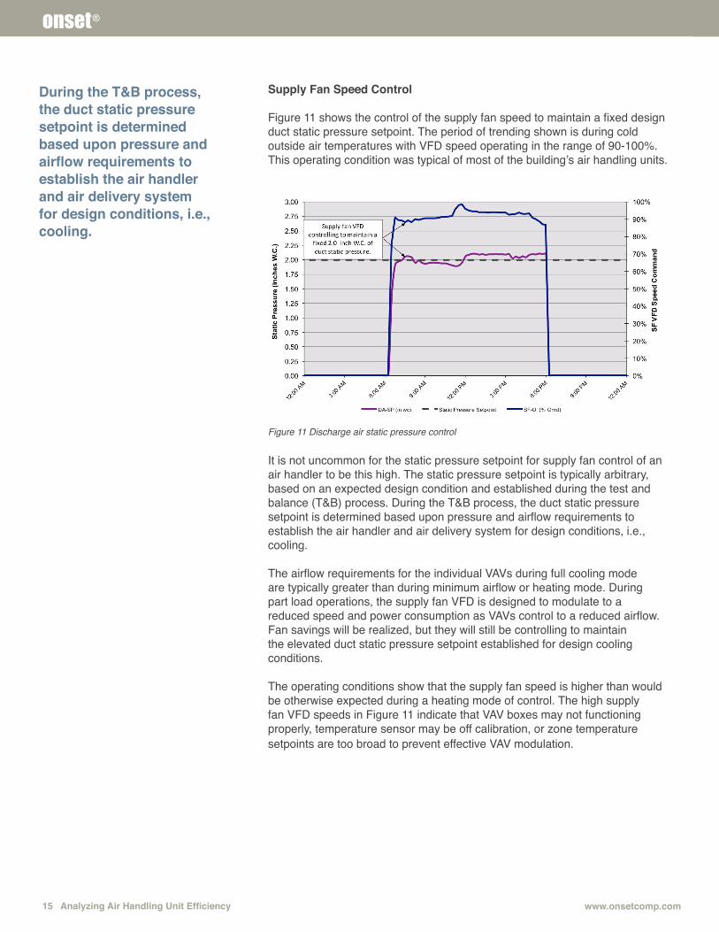
Figure 11 shows the control of the supply fan speed to maintain a fixed design duct static pressure setpoint. The period of trending shown is during cold outside air temperatures with VFD speed operating in the range of 90-100%. This operating condition was typical of most of the building’s air handling units.
Figure 11 Discharge air static pressure control
It is not uncommon for the static pressure setpoint for supply fan control of an air handler to be this high. The static pressure setpoint is typically arbitrary, based on an expected design condition and established during the test and balance (T&B) process. During the T&B process, the duct static pressure setpoint is determined based upon pressure and airflow requirements to establish the air handler and air delivery system for design conditions, i.e., cooling.
The airflow requirements for the individual VAVs during full cooling mode are typically greater than during minimum airflow or heating mode. During part load operations, the supply fan VFD is designed to modulate to a reduced speed and power consumption as VAVs control to a reduced airflow. Fan savings will be realized, but they will still be controlling to maintain the elevated duct static pressure setpoint established for design cooling conditions.
The operating conditions show that the supply fan speed is higher than would be otherwise expected during a heating mode of control. The high supply fan VFD speeds in Figure 11 indicate that VAV boxes may not functioning properly, temperature sensor may be off calibration, or zone temperature setpoints are too broad to prevent effective VAV modulation.
During the T&B process, the duct static pressure setpoint is determined based upon pressure and airflow requirements to establish the air handler and air delivery system for design conditions, i.e., cooling.
Analyzing Air Handling Unit Efficiency 161-800-LOGGERS
onset®
Best Practice Tip:10. For additional fan savings, the duct static pressure setpoint
should be incrementally adjusted downward or upward. This control sequence is known as static pressure reset. This sequence of control will regularly adjust the static pressure setpoint based on the demand requirements of the network of VAVs.
11. Balancing system airflow requirements to match the zone level airflow requirements should be the objective of an efficient air delivery system. Static pressure reset will help facilitate this objective.
Return/Relief Fan Speed Control
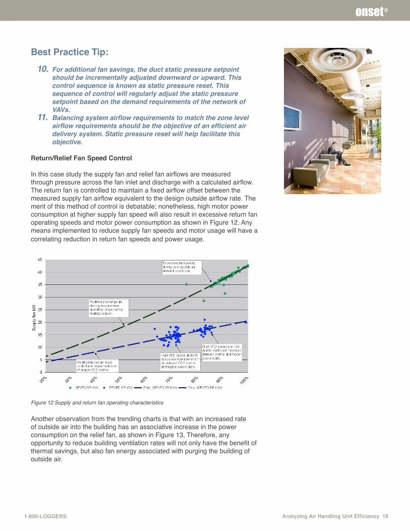
In this case study the supply fan and relief fan airflows are measured through pressure across the fan inlet and discharge with a calculated airflow. The return fan is controlled to maintain a fixed airflow offset between the measured supply fan airflow equivalent to the design outside airflow rate. The merit of this method of control is debatable; nonetheless, high motor power consumption at higher supply fan speed will also result in excessive return fan operating speeds and motor power consumption as shown in Figure 12. Any means implemented to reduce supply fan speeds and motor usage will have a correlating reduction in return fan speeds and power usage.
Figure 12 Supply and return fan operating characteristics
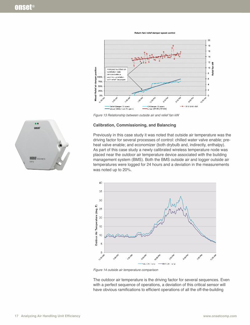
Another observation from the trending charts is that with an increased rate of outside air into the building has an associative increase in the power consumption on the relief fan, as shown in Figure 13. Therefore, any opportunity to reduce building ventilation rates will not only have the benefit of thermal savings, but also fan energy associated with purging the building of outside air.
17 Analyzing Air Handling Unit Efficiency www.onsetcomp.com
onset®
Figure 13 Relationship between outside air and relief fan kW
Calibration, Commissioning, and Balancing Previously in this case study it was noted that outside air temperature was the driving factor for several processes of control: chilled water valve enable; pre-heat valve enable; and economizer (both drybulb and, indirectly, enthalpy). As part of this case study a newly calibrated wireless temperature node was placed near the outdoor air temperature device associated with the building management system (BMS). Both the BMS outside air and logger outside air temperatures were logged for 24 hours and a deviation in the measurements was noted up to 20%.
Figure 14 outside air temperature comparison
The outdoor air temperature is the driving factor for several sequences. Even with a perfect sequence of operations, a deviation of this critical sensor will have obvious ramifications to efficient operations of all the off-the-building
Analyzing Air Handling Unit Efficiency 181-800-LOGGERS
onset®
air handlers. Additional consideration toward device placement must also be evaluated. For example, placement of the static pressure transmitter in a turbulent zone in the main supply air trunk can have an impact on effective and efficient supply fan control. As another example, placement of the mixed air temperature sensor in contact with a chilled water coil can impact process control through the radiation of “coldness” of the coil onto the sensor, impacting the measured value of the mixed air temperature.
Best Practice Tip:12. Regular calibration of this and other critical process-related
control variables must be performed regularly.
It is important to minimize the potential for flow variation due to varying static pressure requirements in the different flow paths as the economizer system modulates from full return to full relief. The particular dampers installed in this case study lacked the linearity necessary to achieve consistent static pressures through all combinations of mixed air damper positions from full economization to minimum outside air mode. The result of the non-linear relationship between damper command and airflow percentage mismatch was resulting in fan starvation, during mixed air control mode, and excessive fan speeds in order to maintain duct static pressure. Damper linearity issues are only one example of an air handler component level issue that can have an impact on effective temperature and pressure control in an air handler.
Best Practice Tip:
13. Validating the most effective sequence of control for an air handling unit requires a rigorous commissioning process. Proper air balancing is also a critical step in achieving energy efficient operations.
This case study demonstrates that an air handler’s sequence of operations can be highly interrelated with regards to operations and energy consumption. In an expansion of this type of investigation it can be shown that operational or control deficiencies can have an integrated response on other system control sequences. In this case study it was examined how VAV operations have a direct impact on air handler operations. An expanded investigation will demonstrate the interrelated impact of air handler operations on central plant pumping and chillers and boiler operations.
Understanding the overall process of control of the entire system sequence of operations provides an overall system corrective strategy. This requires a thorough commissioning or retro-commissioning process with functional performance testing and extensive trending analysis. Trending multiple processes and evaluating the interactive impacts requires an integrated approach toward retro-commissioning. Portable data loggers are cost-effective, reusable, valuable tools in such an endeavor, and can be used in data-gathering and verification.
Understanding the overall process of control of the entire system sequence of operations provides an overall system corrective strategy. This requires a thorough commissioning or retro-commissioning process with functional performance testing and extensive trending analysis.
19 Analyzing Air Handling Unit Efficiency www.onsetcomp.com
onset®
ReferencesTaylor, Steven T., P.E., 2010. Economizer high limit controls and why enthalpy economizers don’t work. ASHRAE Journal. Nov 2010.
Acronyms/AbbreviationsAHU – air handling unitASHRAE – American Society of Heating, Refrigeration and Air Conditioning Engineers BAS – building automation systemBMS – building management systemBTU – british thermal unitCT – current transducerDAT – discharge air temperatureDDC – direct digital controlMAT – mixed air temperatureOAT – outside air temperatureRAT – return air temperature T&B – test and balanceVAV – variable air volumeVFD – variable frequency drive

Analyzing Air Handling Unit Efficiency 201-800-LOGGERS
onset®
Choosing an Occupancy and Light On/Off Data Logger – 5 Important Considerations
This paper provides guidance on features to consider when choosing an occupancy and light on/off data logger, including calibration, LCD display, logger accuracy and range, speed of deployment, and time-saving software. Learn how to select the right logger for identifying ideal locations in your building where changes in lighting could result in cost savings up to 80%.
Utility Incentive Programs: How to Get More Money Quickly and Easily
“Utility Incentive Programs: How to Get More Money Quickly and Easily,” is aimed at making the process of applying for and receiving energy efficiency incentives and rebates faster, easier, and more rewarding. Authored by Carbon Lighthouse, an energy firm that makes it profitable for commercial and industrial buildings to eliminate their carbon footprint, the paper discusses the two main types of incentive and rebate programs, how utility efficiency program managers think, and how to use data to get more incentive dollars for your projects.
Using Data Loggers to Improve Chilled Water Plant Efficiency
Chilled water plant efficiency refers to the total electrical energy it takes to produce and distribute a ton (12,000 BTU) of cooling. System design, water quality, maintenance routines, cooling tower design, and cooling coil load all affect chiller water plant efficiency and the expense of operating the system.
Data Logger Basics
In today’s data-driven world of satellite uplinks, wireless networks, and the Internet, it is common to hear the terms “data logging” and “data loggers” and not really have a firm grasp of what they are.
Most people have a vague idea that data logging involves electronically collecting information about the status of something in the environment, such as temperature, relative humidity, or energy use. They’re right, but that’s just a small view of what data logging is.
Addressing Comfort Complaints With Data Loggers
This paper offers facility managers, HVAC contractors, and others with valuable tips on how low-cost data loggers can be used to validate temperature-related comfort complaints.
Monitoring Green Roof Performance with Weather Stations
Data logging weather stations are the ideal tools for documenting green roof performance. A weather station can measure weather parameters such as rainfall, stormwater runoff, temperature, relative humidity, wind speed, solar radiation, and a host of non-weather parameters such as soil moisture on a continuous basis (say every five minutes, hourly, or an interval appropriate to the situation).
Using Data Loggers Beyond Equipment Scheduling
While data loggers are a great tool for identifying equipment-scheduling opportunities in buildings, their usefulness far exceeds just that one function. This paper discusses how the use of inexpensive data loggers and some spreadsheet analysis can provide all the evidence needed to make powerful building-specific cases for saving money by replacing failed air-handler economizers. It also describes how information from data loggers can be used to accurately calculate the energy savings that can be realized from variable frequency drives (VFDs) on pumps and fans, supply air resets, and boiler lockouts
Analyzing Air Handling Unit Efficiency with Data Loggers
Operating a heating, ventilation and air conditioning (HVAC) system at optimum efficiency in a commercial setting is complicated, to say the least. There is a very real chance that any number of setpoints, levels, and feedbacks at boilers, chillers, pumps, fans, air delivery components and more can cause costly inefficiencies.
Finding Hidden Energy Waste with Data Loggers: 8 Cost-Saving Opportunities
The first step to reducing building energy costs is identifying energy waste. Statistics on utility bills or name plates on equipment, while useful, are not enough to identify what practices and equipment are contributing to high energy use. Portable data loggers can be used to obtain critical energy use information in a wide range of commercial building types – from manufacturing plants to office buildings.
Monitoring HVAC Performance with Data Loggers
Building operators and managers have the difficult job of providing comfortable working conditions and coaxing aging mechanical equipment to operate at peak performance while minimizing energy costs.
Other informational resources available from Onset:
Access our full resources library at: www.onsetcomp.com/learning

onset®
Copyright© 2014, Onset Computer Corporation. All information in this document is subject to change without notice. Onset and HOBO are registered trademarks of Onset Computer Corporation. All other trademarks are the property of their respective owners. All rights reserved. Printed in the USA. Lit. No. MKT1122-0815
About the Author
Michael Rosenberg has over 12 years experience in mechanical engineering design, project management, energy management and systems commissioning. His expertise is focused on analyzing integrated system control and assisting clients in optimizing system operations through the most efficient operational modes of control. He has degrees in Mechanical Engineering and Business and is a licensed professional engineer in the states of Illinois and California. He also holds certifications as a Certified Energy Manager through the AEE and is a LonMark® Certified Professional.
Contact Us
Our goal is to make your data logging project a success. Our product application specialists are available to discuss your needs and recommend the right solution for your project.
About Onset
Onset is a leading supplier of data loggers. Our HOBO data logger products are used around the world in a broad range of monitoring applications, from verifying the performance of green buildings and renewable energy systems to agricultural and coastal research.
Based on Cape Cod, Massachusetts, Onset has been designing and manufacturing its HOBO data loggers on site since the company’s founding in 1981.
Onset headquarters, Cape Cod, MA
Sales (8am to 5pm ET, Monday through Friday) Email [email protected] Call 508-759-9500 In US call toll free 800-564-4377 Fax 508-759-9100
Technical Support (8am to 8pm ET, Monday through Friday) Email [email protected] Call 508-759-9500 In US call toll free 877-564-4377
Onset Computer Corporation470 MacArthur Blvd.Bourne, MA 02532