ANALYTICAL MODELING OF CUTTING FORCE AND CUTTING ...
105
i ANALYTICAL MODELING OF CUTTING FORCE AND CUTTING TEMPERATURE IN TURNING STEEL UNDER CRYOGENIC COOLING CONDITION By Md. Ahasan Habib A Thesis Submitted to the Department of Industrial & Production Engineering in Partial Fulfilment of the Requirements for the Degree of M.Sc. in Industrial and Production Engineering DEPARTMENT OF INDUSTRIAL & PRODUCTION ENGINEERING BANGLADESH UNIVERSITY OF ENGINEERING & TECHNOLOGY DHAKA, BANGLADESH December 2013
Transcript of ANALYTICAL MODELING OF CUTTING FORCE AND CUTTING ...
i
ANALYTICAL MODELING OF CUTTING FORCE AND CUTTING TEMPERATURE IN
TURNING STEEL UNDER CRYOGENIC COOLING CONDITION
By
Md. Ahasan Habib
A Thesis Submitted to the
Department of Industrial & Production Engineering in Partial Fulfilment of the
Requirements for the Degree of
M.Sc. in Industrial and Production Engineering
DEPARTMENT OF INDUSTRIAL & PRODUCTION ENGINEERING
BANGLADESH UNIVERSITY OF ENGINEERING & TECHNOLOGY DHAKA, BANGLADESH
December 2013
ii
The thesis entitled as Analytical Modeling of Cutting Force and Cutting Temperature
in Turning Steel under Cryogenic Cooling Condition submitted by Md. Ahasan Habib,
Student No. 0411082001, Session- April 2011, has been accepted as satisfactory in partial
fulfillment of the requirement for the degree of M. Sc. in Industrial and Production
Engineering on December, 2013.
BOARD OF EXAMINERS
1. Dr. Nikhil Ranjan Dhar Chairman Professor
Department of Industrial & Production Engineering BUET, Dhaka
2. Head Member Department of Industrial & Production Engineering
BUET, Dhaka.
(Ex-officio)
3. Dr. A.K.M. Masud Member Professor
Department of Industrial & Production Engineering BUET, Dhaka.
4. Dr. A.F.M. Anwarul Haque Member Professor & Head
Department of Mechanical & Production Engineering Ahsanullah University of Science & Technology (AUST) Dhaka.
(External)

iii
Declaration
It is hereby declared that this thesis or any part of it has not been submitted elsewhere for
the award of any degree or diploma.
Md. Ahasan Habib
iv
This work is dedicated to my Loving Parents
Md. Fazlur Rahman
and Asia Begum
v
ACKNOWLEDGEMENT
I would like to acknowledge my respected supervisor, Dr. Nikhil Ranjan Dhar,
Professor, Department of Industrial & Production Engineering (IPE), BUET for his
guidance and support during my post-graduate career which cannot be expressed through
words only. I consider it to be a great honor to work under him. I am grateful and indebted
to him forever for his constant encouragement and supports for becoming a competitive
engineer, a strong researcher and obviously a good human being.
I would like to express my gratitude and thanks to the board of examiners Dr.
Sultana Parveen, Professor, Department of Industrial & Production Engineering, BUET,
Dr. A.K.M. Masud, Professor, Department of Industrial & Production Engineering, BUET
and A.F.M. Anwarul Haque, Professor & Head, Department of Mechanical and Production
Engineering, AUST, for their valuable suggestions and guidance.
I am deeply obliged to Prianka Binte Zaman, Assistant Professor, IPE
Department, BUET for her availability during experimental work and special thanks goes
to Dr. T.P. Bhowmick, Professor & Head, Department of Industrial Engineering &
Management, KUET, for giving permission, help and encouragement. The help extended
by the British Oxygen Company (BOC), Bangladesh for supplying liquid nitrogen to carry
out the work is also sincerely acknowledged.
I also acknowledge the help rendered by the Director, DAERS, BUET who
provided machine shop facilities whenever required. I would like to express my heartfelt
gratitude to all the staff members of Central Machine Shop and Machine Tools Lab who
have helped a lot whenever required, especially Manik Chandra Roy, M. A. Razzak, Tony
G. Gomes and Shankar Chandra Das for their helps in conducting the experimental work.

vi
ABSTRACT
In the machining operation the energy dissipated is converted into heat which
raises the temperature in the cutting zone. The increase of cutting temperature results tool
wear, surface roughness, dimensional inaccuracy significantly. Not only is the cutting
temperature, cutting force also increases with tool wear which results the increase of
power and specific energy consumption. The cutting temperature restrains productivity,
quality and hence machining economy, can be controlled by the application of cutting
fluid. But conventional cutting fluids are ineffective to control the temperature in
maximum cutting zones. So cryogenic cooling is environmental friendly new approach to
control the temperature desirably. Cryogenics is the study of the production of very
low temperature (-196°C) and the behavior of materials at that temperature. The physical
behavior during metal cutting has been changed because of cutting condition, cutting
environment and work/tool material.
The aim of the present work is to investigate the role of cryogenic cooling on the
formation of chip, cutting temperature and force and then develop analytical model for
cutting temperature and force in turning 42CrMo4 steel under cryogenic cooling condition.
The m.files of matlab has been used to determine the modeled value of cutting force and
cutting temperature under cryogenic cooling condition. From an economic viewpoint, it is
evident that having knowledge about the machining responses such as, cutting forces,
cutting temperature and work piece surface integrity at different cutting conditions would
be highly desirable as a means of realizing cost savings, increased productivity, efficiency
and for preventing any hazard occurring to the machine, cutting tool or the deterioration of
the quality.
vii
LIST OF TABLES
Table 2.1 : Experimental conditions 34
Table 2.2 : Shape and color of chips produced during turning 42CrMo4 steel by
SNMG insert under dry and cryogenic cooling conditions
35
Table 3.1 : Test conditions for temperature validation 51
Table 4.1 : Regression analysis between the cutting velocity and the effect of
cutting velocity on the main cutting force
68
Table 4.2 : Regression analysis between the feed rate and the exponent 69
Table 5.1 : Percentage error of chip tool interface temperature under dry and
cryogenic cooling condition
74
Table 5.2 : Percentage error of Pz under dry and cryogenic cooling condition 75
Table 5.3 : Percentage error of Px under dry and cryogenic cooling condition 76

viii
LIST OF FIGURES
Fig. 2.1 : Photographic view of the experimental set up 33
Fig. 2.2 : Schematic view of the formation of chip 35
Fig. 2.3 : Variation in chip reduction coefficient (ξ) with that of Vc and So in
turning 42CrMo4 steel by SNMG insert under dry and cryogenic
cooling conditions
36
Fig. 2.4 : Variation in average interface temperature (θ) with that of Vc and So
in turning 42CrMo4 steel by SNMG insert under dry and cryogenic
cooling conditions
38
Fig. 2.5 : Variation in main cutting force (Pz) with that of Vc and So in turning
42CrMo4 steel by SNMG insert under dry and cryogenic cooling
conditions
39
Fig. 2.6 : Variation in feed force (Px) with that of Vc and So in turning
42CrMo4 steel by SNMG insert under dry and cryogenic cooling
conditions
40
Fig. 3.1 : Schematic view of (a) the frictional heat source at chip tool interface
(b) the frictional heat source at chip tool interface considering as a
stationary rectangular heat source
43
Fig. 3.2 : Heat sources in metal cutting process 44
Fig. 3.3 : Heat sources and heat loss for the 2D model 46
Fig. 3.4 : Moving of source of shear plane 47
Fig. 3.5 : Stationary source of heat at chip tool interface 48
Fig. 3.6 : Comparison of actual and predicted cutting temperature for different
combinations of cutting velocity and feed rate under cryogenic
condition
52
Fig. 4.1 : Plastic formation zones of metal cutting 53
Fig. 4.2 : Orthogonal metal cutting process 54
Fig. 4.3 : Oblique metal cutting process 54
Fig. 4.4 : Deck-of-Cards chip formation model (a) Parallel shear plate (b)
Thickness plate (c) Relation of angle [Piispanen1948]
55
Fig. 4.5 : Merchant’s shear plane force circle 56
Fig. 4.6 : Lee and Shaffer’s slip line filed model [Lee and Shaffer 1951] 59
ix
Fig. 4.7 : Okushima and Hitomi's model 61
Fig. 4.8 : Zorev's schematic representation of lines of slip in chip formation
zone [Zorev1998]
61
Fig. 4.9 : Oxley's shear zone model [Oxley1997] 62
Fig. 4.10 : Force components of conventional turning process 67
Fig. 4.11 : Comparison of measured and predicted main cutting force for
different combinations of cutting velocity and feed rate under
cryogenic condition
71
Fig. 4.12 : Comparison of measured and predicted feed force for different
combinations of cutting velocity and feed rate under cryogenic
condition
71

x
LIST OF SYMBOLS
a1 : Uncut chip thickness
a2 : Chip thickness
A : Percent of this energy is converted into heat
A : Area factor
BHN : Brinell Hardness number
b1 : Width of chip
c, : Specific heat
c1, c2 : Partition Coefficient
Cn : Natural contact length
e : Error
Ef : Rate of expansion of friction energy
Es : Rate of expansion of share energy
F : Component of frictional force directed along the tool rake face
HSM : High speed machining
J : Mechanical equivalent of heat in kg.cm/cal
Ky : Coefficient, the effect of rake angle for x, z direction
K∅ : Coefficient, the effect of principle cutting edge for x, z direction
K : Coefficient, the effect of tool wear for x, z direction
K : Coefficient, the effect of cutting fluid used for x, z direction
K : Material transfer coefficient for x, z direction
Ko (u) : Modified Bessel function of second kind and zero order
Ko (x) : Modified Bessel function of second kind of order zero
푙 : Natural contact length
l : Distance along x-axis
L,L1 : Dimensionless velocity parameter
MRR : Material removal rate
n : Exponent of feed rate
N : Normal force
m : Distance along y-axis
m1 : Exponent of BHN
M : Resultant force

xi
L2 : Dimensionless velocity parameter for friction
p : Exponent of t
Ps : Shear force
Px : Feed force
Py : Thrust force
Pz : Main cutting force
q : Heat flux
qs : Heat generated due to intensive plastic deformation
qr
: Heat source generated due to tip radius of the cutting tool
q : rate of heat liberated at chip-tool interface
q1, q2 : The heat liberated at the interface
r : Nose radius
R : Resultant distance of cutting point
R1, R2 : Constant
So : Feed rate
T : Time
T : Modified temperature
T : Time for a specific point
t : Chip thickness
uf : Specific energies involved in shear
us : Specific energies involved in friction
ucf : Energy per unit volume going to the chip on chip-tool interface
ucs : Energy per unit volume going to the chip on the shear plane
V : Velocity of moving heat source
Vc : Cutting velocity
Vf : Chip flow velocity
Vs : Volume of shear zone
X : Dimensionless velocity parameter along x-axis
Y : Dependent response variable
θi : Chip-tool interface temperature
θavg : Average temperature
θm : Maximum temperature

xii
θs : Final shear zone temperature
θ ,θc : Ambient temperature in 0C
θ : Mean temperature of the shear plane
∅ ,∅ : Inclination angle
∅ : Angle of the arbitrary radial plane
Ѱ : Angle of inclination formed by the tangential
∆θ : Temperature rise
φ : Principal cutting edge angle
훼 : Rake angle
∅ : Shear angle
훽 : Friction angle η : Mean angle of friction at the rake surface
훿 : Thermal diffusivity
φ(T) : Heat liberation rate
λ : Thermal conductivity
휌푐 : Volume specific heat
휌,휌 : Density
휏 : Dynamic yield shear strength
휀 : Shear strain
휇 : Mean angle of friction at the rake surface
ξ : Chip reduction co-efficient
xiii
CONTENTS Acknowledgements........................................................................................... vAbstract............................................................................................................. viList of Tables.................................................................................................... viiList of Figures................................................................................................... viiiList of Symbols................................................................................................. xChapter 1 Introduction............................................................................ 1 1.1 High Speed Machining …………………………….…….….……. 2 1.2 Machining under Cryogenic Cooling Condition…………….……. 3 1.3 Literature Review…………………………………………………. 6 1.3.1 Effects of Conventional Cutting Fluids …………………….. 6 1.3.2 Effects and Control of Cutting Temperature……….………. 7 1.3.3 Modeling of Cutting Temperature …….…………………… 14 1.3.4 Modeling of Cutting Forces………….. ……………………. 20 1.4 Summary of the Review……………………….……………..…… 29 1.5 Scope of the Thesis…………………………………………..…… 30 1.6 Objectives of the Present Work........................................................ 31Chapter 2 Experimental Investigations.......................................................... 32 2.1 Experimental Procedure and Conditions.......................................... 32 2.2 Experimental Results....................................................................... 34 2.2.1 Chip Formation …………………………………………….. 34 2.2.2 Cutting Temperature………………………………………... 37 2.2.3 Cutting Forces………………………………………………. 39Chapter 3 Modeling of Cutting Temperature …........................................... 41 3.1 Temperature Rise due to Heat Source.............................................. 41 3.2 Modeling of Cutting Temperature……………………................... 44 3.3 Experimental Model Validation of Cutting Temperature............... 51Chapter 4 Modeling of Cutting Force 53 4.1 Thin Shear Plane and Thick Deformation Zone Model…………... 55 4.2 Modeling of Cutting Forces……………….……………………… 63 4.3 Experimental Model Validation of Cutting Forces……………….. 70Chapter 5 Discussion on Results………………………………………. 72 5.1 Cutting Temperature….................................................................... 72 5.2 Cutting Forces.…………………………………..………………... 74Chapter 6 Conclusions ……………………………………….………....…... 77 6.1 Conclusions …………………………………………………….… 77 6.2 Scope for Future Work……………………………………………. 78References......................................................................................................... 80
1
The most promising inclination of the modern metal cutting operation is high
material removal rate (MRR) with good surface finish and high machining accuracies. All
the machining on the metal as well as on the alloy where plastic deformation is related to
form chip, huge energy is required and this energy is converted into heat and finally
increase the cutting-zone temperature. This is a great concern of the performance of the
cutting tool and the excellence of the workpiece. Temperatures in cutting zone depend on
contact length between tool and chip, cutting forces and friction between tool and
workpiece material. A significant amount of heat generated during machining is
transferred into cutting tool and workpiece and other portion of the heat is removed with
chip. So the cutting condition and the performance of tool and tool life depend on contact
length between the tool and chip.
Chip-tool interface temperature, chip morphology, chip-tool interaction, cutting
forces, wear and life of cutting tool, dimensional accuracy and surface integrity along with
surface finish under different cutting environments with or without using cutting fluids are
potential topics to research in the modern world. As the usages of different conventional
cutting fluids are creating health hazard and intend to create pollution so research are
expanding with completely dry cutting using high heat and wear resistant cutting tools,
cryogenic machining, high-pressure coolant jet assisted machining and minimum quantity
lubricant machining and their technological effects particularly in temperature intensive
machining and grinding.
A summary of this promising topics and the background of this research will be
represented in this chapter. The bad effect of rising temperature at the cutting zone, effect
of cryogenic condition on cutting forces and cutting temperature will be discussed
Chapter-1
Introduction
2
thoroughly in this chapter. Related literature of research works with different necessary
parameters will also be described in this chapter.
1.1 High Speed Machining
A material will be defined as good machinability if it is easy to cut it according to
the desire shape and size with respect to tooling and machining process involved. This
machinability is measured with respect to the tool life; MRR, cutting force and power
consumption, surface finish generated and surface integrity of the machined component as
well as the shape of the chips. The machinability index can also significantly be
exaggerated by the properties of the material being machined, properties and geometry of
the cutting tool, cutting conditions employed and cutting environment etc. Machining
productivity can be significantly improved by employing the right combination of cutting
tools, cutting conditions, machine tool and cutting environment that will promote high
speed machining without compromising the integrity and tolerance of the machined
components.High-speed machining is one of advanced production technologies with great
future potential.The most obvious rationale for pursuing a study of high-speed machining
(HSM) is the promise of increased MRR, which is the product of surface speed, depth of
cut, and feed rate. While HSM generally means high surface speed, most practical
applications also require some minimum chip load and this means a feed rate above a
minimum value. A speed above which shear-localization develops completely in the
primary shear zone is known as high-speed. For the creation of such type of shear
localization, a huge amount of heat generates at the chip tool interface, which leads a very
high cutting temperature [Kitagawa et al. 1997]. This huge amount of cutting temperature
not only reduces dimensional accuracy and tool life but also impairs the surface integrity
of the product [Chattopadhyay and Chattopadhyay 1982]. The rapid wear rate of cutting
tools due to high cutting temperature is a critical problem to be solved in HSM of hardened
steels. In recent years, HSM technology is becoming matured owing to the advance of
machine tool and control system. In comparison with the conventional methods, HSM not
only exhibits a higher metal removal ate but also results in lower cutting force, better
surface finish, no critical heat of the workpiece, etc.
Reduction of finishing operations, elimination of part distortion, achievement of
high metal removal rates and lower machining costs as well as improved surface integrity
3
are some great advantages of HSM. It can also be used when huge temperature and stress
are required at the position of tool-workpiece interface. Still cost effective application of
this technology requires a fundamental understanding of the relationships between process
variables. So the understanding of how amount of temperature and stress are produced
during machining operations. This will really reduce the requirement of time and cost
[Sekhon and Chenot 1993].
The places where high speed looks intricate in action, there depth of cut can be a
good solution. This can be accomplished only with a high-power, adequately rigid
machine tool. The part should also be stiff enough to yield the required accuracy and finish
under these cutting conditions. All these experiments have given a proof and undoubtedly
accepted in modern time that HSM has a good efficiency in cost, time and accuracy.
1.2 Machining under Cryogenic Cooling Condition
Cryogenics is the field related to technology at deep freezing temperatures.
Traditionally, the field of cryogenics is taken to start at temperatures below -196°C. The
definition includes the more common cryogenics such as helium, hydrogen, neon,
nitrogen, oxygen, argon, krypton, xenon, methane, ethane, and propane. Carbon dioxide is
commonly added to the list even though a pressure over 50 KPa is required to maintain it
in liquid form. Even the term "cryogenics" seem like an esoteric field, it plays a major role
in modern industry and science. Some of the applications are: air separation plants for
breaking it down into its components for industrial and medical uses, liquefied helium has
become unavoidable cooling element of magnetic resonance imaging systems in modern
hospitals, in space technology where cryogenics are through the liquefied hydrogen and
oxygen used as fuels, food freezing and cooling, purging and blanketing, etc.The
beginning of cryogenic is going back in the beginning of the nineteenth century where
there was a “race" in liquefying gases and reaching ever lower temperatures. This started
with the announcement of the liquefaction of oxygen by Pictet and Cailletet [1887]. James
Dewar [1898] first liquefied hydrogen. He also developed the vacuum-insulated flask for
containing cryogenic liquids that are still frequently used and are called "Dewars". The last
and most difficult gas to be liquefied was helium, liquefied by Kamerlingh Onnes of
Lieden [1908]. As a twentieth century progress, industrial application of cryogenics
increased, particularly in the area of air liquefaction and industrialization.

4
The most practical and effective way to enhance the machining performance in
cutting difficult-to-cut materials is to reduce the cutting temperature. One way of reducing
the cutting temperature is to use a cutting coolant. Cutting fluids are used in conventional
machining to extend tool life by reducing tool temperature and friction between the tool,
the chip and the workpiece in the cutting process. However, conventional coolants contain
different chemicals that may cause water pollution, soil contamination and health problems
if disposed without required treatments. Another way of reducing the cutting temperature
is to use a cryogenic coolant. In Cryogenic machining, liquid nitrogen (LN2) is used as a
coolant, is considered a viable option to conventional machining. Having a temperature as
low as −196 °C at 101.325 KPa, super cold LN2 is a good coolant. After absorbing the heat
dissipated from the cutting process, it evaporates into nitrogen gas and becomes part of the
air (79% of the air is nitrogen). It leaves no harmful residue to the environment. Therefore,
it is considered to be environment friendly due to this natural recycling.
Wang et al. [1996] have carried out turning of ceramics (Si3N4) with
polycrystalline cubic boron nitride (PCBN) under cryogenic cutting conditions and
reported that liquid nitrogen cooling system reduced the cutting tool temperature and tool
wear over dry machining. Hong and Ding [2001] conducted an experiment with various
cooling approaches in cryogenic machining of Ti-6Al-4V. Temperatures in cryogenic
machining were compared with conventional dry cutting and emulsion cooling. It was
showed that a small amount of liquid nitrogen applied locally to the cutting edge is
superior to emulsion cutting in lowering the cutting temperature. Hong et al. [2001] have
carried out experimental investigation into the role of cryogenic cooling by liquid nitrogen
on friction and cutting force in machining of Ti-6Al-4V. The experimental results
indicated that cutting force was increased in cryogenic machining. It was also found that
the friction coefficient on the tool-chip interface was considerably reduced in cryogenic
machining. Dhar et al. [2002] involved experimental investigation of cryogenic cooling on
tool wear, surface roughness and dimensional deviation in turning of AISI 4140 steel by
two different geometries of carbide inserts. Substantial benefit of cryogenic cooling on tool
wear, surface roughness and dimensional deviation was reported. Dhar and Kamruzzaman
[2007] conducted an experiment on cryogenic machining and stated that benefits of
cryogenic cooling are mainly by substantially reducing the cutting temperature, which
improves the chip-tool interaction and maintains sharpness of the cutting edge and also
5
shows better surface finish and higher dimensional accuracy as compared to dry and wet
machining.
Paul et al. [2006] investigated the tool wear and tool life of carbide inserts in
turning of Ti-6Al-4V alloy under dry, wet and cryogenic environment. It was found that
tool wear parameters are less in cryogenic environment. Ahmed et al. [2007] conducted the
experiment in cryogenic machining of AISI 4340 steel with modified tool holder. Two
different flow outlets were tested for this modified tool holder. It was found that this
modified tool holder for cryogenic cooling is more effective when the coolant out flow is
directed away from the cutting edge of the carbide insert. Kumar and Choudhury [2008]
studied the effect of cryogenic cooling on tool wear and high frequency dynamic cutting
forces generated during high speed machining of stainless steel. It was showed that
cryogenic cooling was effective in bring down the cutting temperatures that attributed for
the substantial reduction of the flank wear. The main functions of cryogenic machining
include (i) removing heat effectively from the cutting zone, hence lowering cutting
temperatures, (ii) modifying the frictional characteristics at the tool/chip interfaces, and
(iii) changing the properties of the workpiece and the tool material [Uehara et al. 1970].
In cryogenic machining, different cooling strategies are needed in order to solve
the problems specific to the individual materials being machined. These strategies, which
this may serve different purposes, include:
i) freezing the workpiece
ii) delivering the cryogen to the tool/chip or tool/work interface,
iii) cooling the cutting tool and chip
To choose cooling strategies, the properties of both the tool materials and the
workpiece materials must be considered because they are fundamental in determining the
machining characteristics. The desirable properties of tool materials generally include high
hardness and wear resistance, high toughness and strength to resist various forms of
fractures, and low chemical affinity with the workpiece. Properties of the workpiece
materials become problematic when their hardness and strength are abrasive to cutting
tools and these properties cause a high compressive stress to act on the cutting edge,
raising the cutting temperatures. The materials’ ductility and toughness affect the chip
6
formation process. Highly ductile materials, for instance, are likely to produce continuous
chips and built-up edges [Hong et al. 1999 and Yildiz et al. 2008].
Cryogenic machining of stainless steel, which is equivalent to AISI 304, has been
studied in Japan. And it was reported that the cutting force was increased as the workpiece
temperature was decreased to cryogenic temperatures [Uehara et al. 1968]. A milling
study by Dillon et al. [1990] reported an increased difficulty in machining AISI 304 at
reduced temperatures. Therefore, AISI 304 is considered to be a poor candidate for
successful cryogenic machining. It was stated that if a new cryogenic cooling approach
could provide effectiveness in machining this material, it would prevail in cutting other
materials.
1.3 Literature Review
1.3.1 Effects of Conventional Cutting Fluids
A cutting fluid can be defined as any substance which is applied to a tool during a
cutting operation to facilitate removal of chips. Cutting fluids have been used extensively
in metal cutting operations for the last 200 years. In the beginning, cutting fluids consisted
of simple oils applied with brushes to lubricate and cool the machine tool. Occasionally,
lard, animal fat or whale oil was added to improve the oil's lubricity. As cutting operations
became more severe, cutting fluid formulations became more complex. Today’s cutting
fluids are special blends of chemical additives, lubricants and water formulated to meet the
performance demands of the metalworking industry.
The application of cutting fluids is another alternative to obtain higher material
removal rates. Cutting fluids have been used widespread in all machining processes.
However, because of their damaging influences on the environment, their applications
have been in machining processes. New for elimination of cutting fluids application in
machining processes has been examined and “dry machining” was presented as a
important solution. The development of new cutting tool materials also helped dry
machining method to be a positive solution for cutting fluids applications. However, the
usage of cutting fluids has been increased due to high production levels in the world.
According to Values [1998], 2.3x10⁹ liter cutting fluids have been used in the machining
operations and its cost value was around $ 2.75x10⁹. First study about cutting fluids had
been determined by Northcott [1868]. In the middle of 1890’s, F.W. Taylor emphasized
7
that using cutting fluids would allow to use higher cutting speeds resulting in longer tool
life and higher material removal rates. It had been concluded that the application of cutting
fluids in machining processes would make shaping process easier. In this study, the studies
about cutting fluid application in processes have been evaluated. The selection criteria of
cutting fluids have been examined. Suitable cutting fluids for various material machining
processes have been determined according to cutting tool materials. The cutting fluids
applied in machining processes basically have three characteristics. These are:
i) cooling effect
ii) lubrication affect
iii) taking away formed chip from the cutting zone
The cooling effect of cutting fluids is the most important parameter. It is
necessary to decrease the effects of temperature on cutting tool and machined workpiece.
Therefore, a longer tool life will be obtained due to less tool wear and the dimensional
accuracy of machined workpiece will be improved. The lubrication effect will cause easy
chip flow on the rake face of cutting tool because of low friction coefficient. This would
also result in the increased by the chips. Moreover, the influence of lubrication would
cause less built-up edge when machining some materials such as aluminum and its alloys.
As a result, better surface roughness would be observed by using cutting fluids in
machining processes. It is also necessary to take the formed chip away quickly from
cutting tool and machined workpiece surface. Hence the effect of the formed chip on the
machined surface would be eliminated causing poor surface finish. Moreover part of the
generated heat will be taken away by transferring formed chip.
1.3.2 Effects and Control of Cutting Temperature
Due to the excessive heat at the interface of tool-workpiece, the strength,
hardness, stiffness and wear-resistance of the cutting tool are affected even the tool
becomes soften goes through plastic deformation and as a result the dimension of the tool
becomes changed and eventually results tool failure. So there is a great impact of tool-chip
temperature on the rate of tool wear [Usui et al. 1978]. High temperatures at the tool–chip
interface result in an increase of diffusion and chemical wear [Endrino et al. 2006]. The
high specific energy required in machining under high cutting velocity and unfavorable
condition of machining results in very high temperature [Chattopadhyay and
8
Chattopadhyay 1982, Singh et al. 1997]. At elevated temperature and pressure the
cutting edge deforms plastically and wears rapidly, which lead to dimensional inaccuracy,
increased cutting forces and premature tool failure [List et al. 2005]. Increasing cutting
forces result the increase of power consumption. Tool wear and increased heat can induce
thermal damage and metallurgical changes in the machined surface. The experimental
results show that tool wear is a dominant factor affecting the values of induced residual
stress, strain, subsurface energy, and the quality of the machined surface. The increase of
tool wear caused an increase of residual stress and strain beneath the machined surface. It
was also found that the overall energy stored in the machined subsurface increases as the
tool wear increases and as the tool surface gets rougher. Rapid increase in notching occurs
on carbide tools at higher cutting speed which usually leads to the premature fracture of
the entire insert edge [Ezugwu and Bonney 2004]. Flank wear causes an increase in the
cutting force and the interfacial temperature, leading normally to dimensional inaccuracy
in the work pieces machined and to vibration which makes the cutting operation less
efficient [Bouzid et al. 2004].
Innately high cutting zone temperature is generated at high production (high
speed-feed rate). Uncoated carbide insert creates more cutting temperature than coated
insert when turning different steels [Sultana et al. 2009].Turning difficult to cut materials
(Stainless steel, Titanium, Inconel etc.) using existing conventional techniques is an un-
economical as the turning process results in high tool wear, takes longer time and require
high cutting force [Khan and Ahmed 2008]. The generation of heat was very high while
turning these materials due to strong adhesion between the tool and work material resulting
from their low thermal conductivity, high work hardening rate, high viscosity, high
reactivity, tendency to form built-up-edge (BUE) at tool edge compared to other alloy
steels. The contact length between the tool and chip has a direct influence on the cutting
temperatures and the amount of heat energy that is dissipated in the tool which enhances
thermally activated chemical wear and it was observed by Vleugels [1995]. Strafford and
Audy [1997] investigated the relationship between hardness and machining forces during
turning of AISI 4340 steel with mixed alumina tools. The results suggest that an increase
in hardness leads to an increase in the machining forces. Liu et al. [2002] observed that the
cutting temperature is optimum when the work piece material hardness is HRC 50. With
further increase in the work piece hardness, the cutting temperature shows a descending
tendency. Liu et al. [2002] also suggests that, under different cutting parameters, the role
9
of cutting force changes with work piece hardness. The main cutting force features an
increasing tendency with the increase of the work piece hardness.
The hardness, plastic modulus and the fracture toughness of the tool decline with
increase in cutting temperature, which accelerates tool wear rate was observed by Reed
and Clark [1983]. Moreover, thermal stresses in the tool increase with the temperature
resulting in more cracks in the tool and premature failure of the tool. The amount of energy
dissipated through the rake face of the tool raises the temperature at the flanks of the tool
[Wu and Matsumoto 1990]. The cutting temperature and force are tried to be controlled
or reduced to some extent by
i) appropriate selection of process parameters
ii) appropriate selection of cutting tool geometry
iii) proper selection of cutting tools and
iv) proper selection and application of cutting fluids
Appropriate selection of the levels of the process parameters (cutting velocity,
feed rate and depth of cut) can provide better machinability characteristics of a given
work-tool pair even without sacrificing productivity or MRR. Amongst the process
parameters, depth of cut, plays least significant role and is almost invariable compared to
feed (So) variation of cutting velocity (Vc) governs machinability more predominantly.
Increase in Vc, in general, reduces tool life but it also reduces cutting forces or specific
energy requirement and improves surface finish through favorable chip-tool interaction.
Some cutting tools, especially ceramic tools perform better and last longer at higher Vc
within limits. Increase in feed raises cutting forces proportionally but reduces specific
energy requirement to some extent. Cutting temperature is also lesser susceptible to
increase in So than Vc. But increase in So, unlike Vc raises surface roughness. Therefore,
proper increase in Vc, even at the expense of So often can improve machinability quite
significantly [Sun et al. 2005]. Hasçalık and Çaydaş [2008] showed that feed rate and
cutting speed were the most influential factors on the surface roughness and tool life,
respectively. The surface roughness was chiefly related to the cutting speed, whereas the
axial depth of cut had the greatest effect on tool life.
The geometrical parameters such as; tool rake angles, clearance angle, cutting
angles, nose radius, inclination angle and depth, width, form of integrated chip breaker of
10
cutting tools significantly affect the machinability of a given work material under given
machining conditions. Increase in tool rake angles reduces main cutting force through
reduction in cutting strain, chip reduction coefficient. Presence of inclination angle
enhances effective rake angle and thus helps in further reduction of the cutting forces. The
variation in the principal cutting edge angle influences feed force and the cutting
temperature quite significantly. Feed force, if large, may impair the product quality by
dimensional deviation and roughening the surface due to vibration. Inadequate clearance
angle reduces tool life and surface finish by tool-work rubbing, and again too large
clearance reduces the tool strength and hence tool life. Proper tool nose radius improves
machinability to some extent through increasing in tool life by increasing mechanical
strength and reducing temperature at the tool tip. Thus it reduces the surface roughness.
Proper edge radius also often enhances strength and life of the cutting edge without much
increase in cutting forces.
What the work material is not the factor, the cutting tool plays a significant role
on the performance of the conventional machining operation. For instance, alterations in
the cutting edge preparation will result in changes in tool wear rate, cutting forces,
temperature, and machined surface finish. The results indicated that, in general, the turning
force components are reduced with the tool nose radius and the specific cutting force
decreased as feed rate is elevated, presenting values comparable to metallic alloys. Finally,
for the elevation of feed rate and reduction of the nose radius the surface roughness will be
increased [Leonardo and Davim 2009]. Tool geometry is another important factor
affecting machining forces, above all the feed (axial) and thrust (radial) force components
[Thiele and Melkote 1999]. The use of large nose radius together with low depths of cut
lead to low true side cutting edge angle values, thus resulting in high thrust forces [Muller
and Blumke 2001]. Rahman et al. [1997] investigated the machinability index of Inconel
718 subjected to various machining parameters including tool geometry, cutting speed and
feed rate on flank wear, surface roughness and cutting force as the performance indicators
for tool life. They observed that tool life increases with the increase in side cutting edge
angle for the inserts and the heat generated during the cutting process is distributed over a
greater length of cutting edge. This improves the heat removal from the cutting edge,
distributes the cutting forces over a larger portion of the cutting edge, reduces tool
notching and substantially improves tool life.

11
Ezugwu and Tang [1995] have shown that most of the major parameters including
the choice of tool and coating materials, tool geometry, machining method, cutting speed,
feed rate, depth of cut, lubrication, must be controlled in order to achieve adequate tool
lives and surface integrity of the machined surface. In machining a given material, the tool
life is governed mainly by the tool material which also influences cutting forces and
temperature as well as accuracy and finish of the machined surface. The composition,
microstructure, strength, hardness, toughness, wear resistance, chemical stability and
thermal conductivity of the tool material play significant roles on the machinability
characteristics though in different degree depending upon the properties of the work
material. High wear resistance and chemical stability of the cutting tools like coated
carbides, ceramics, cubic boron nitride (CBN) etc also help in providing better surface
integrity of the product by reducing friction, cutting temperature and BUE formation in
high speed machining of steels. Very soft, sticky and chemically reactive material like pure
aluminium attains highest machinability when machined by diamond tools.
Two of great important materials cubic boron nitrate (CBN) and polycrystalline
diamonds (PCD) cutting tools have been found important place in machining processes.
Cubic boron nitride can maintain its hardness and resistance to wear at elevated
temperatures and has a low chemical reactivity to the chip/tool interface [Narutaki and
Yamane 1979].
The basic purposes of employing cutting fluid are to improve machinability
characteristics of any work-tool pair through improving tool life by cooling and
lubrication, reducing cutting forces and specific energy consumption and improving
surface integrity, size accuracy by cooling, lubricating and cleaning at the cutting zone in
metal cutting process. Cutting fluids also make chip-breaking and chip-transport easier.
For reducing the cutting zone temperature through cooling and lubricating action a copious
amount of fluid is flushed into the cutting zone to facilitate heat transfer from the cutting
zone. Lubricants reduce friction and coolants effectively reduce high cutting temperature
of tools/work pieces. It can flush chips away from the cutting zone, protect the machined
surface from environmental corrosion and these factors improve tool life and help make a
better more efficient cut [Beaubien and Cattaneo 1964]. On the other hand, using a
cutting fluid may cause the material to become ‘curly’, which concentrates the heat closer
to the tip. This is detrimental because it decreases the tool’s life. Some conditions like
12
machining steels by carbide tools, the use of coolant may increase tool wear [Paul et al.
2001] though it can reduce temperature. In case of high speed-feed machining, which
inherently generated high cutting zone temperature, cutting fluid can’t reduce the
temperature because fluid can’t reach to the chip-tool interface [Dhar et al. 2002]. The
favorable roles of cutting fluid application depend not only on its proper selection based on
the work and tool materials and the type of the machining process but also on its rate of
flow, direction and location of application. Proper selection and application of cutting fluid
generally improves tool life. At low cutting speed almost four times longer tool life was
obtained by such cutting fluid [Satoshi et al. 1997] but not improve significantly.
As conventional cutting fluids have some technological problems, additional
cutting fluid systems are needed in industry to deliver fluid to the cutting process, re-
circulate fluid, separate chips and collect fluid mist. Moreover, for using cutting fluid
environment becomes polluted. Because, for improving the lubricating performance Sulfur
(S), Phosphorus (P), Chlorine (Cl) or other pressure additives are mixed with cutting fluid
[Peter et al. 1996]. If the cutting fluids are not handled appropriately, it may damage soil
and water resource, which can cause serious environment pollution. Sokovic and
Mijanovic [2001] have shown additionally, in the factory cutting fluid may cause skin and
breathing problem of the operator. In flood cooling method, fluid is used in very large
amount (6-10 l/hr). The cost associated with the use of cutting fluid is estimated to be
about 16% to 20% of the total manufacturing costs [Byrne and Scholta 1993, Brockhoff
and Walter 1998], where only 4% of the total manufacturing cost is associated with
cutting tools [Aronson 1995]. So, in respect of costs, it is very important to reduce the
amount of cutting fluid. Some conditions like machining steels by carbide tools, the use of
coolant may increase tool life. In flood cooling method, fluid is used in very large amount
(6-10 l/hr. So, in respect of costs, it is very important to reduce the amount of cutting fluid.
Some conditions like machining steels by carbide tools, the use of coolant may increase
tool wear [Paul et al. 2001].
Furthermore coolants and lubricants incur a significant part of the manufacturing
cost. For instance in the production of camshafts in European automotive industry, the cost
of coolants/lubricants constituted 16.9% of the total manufacturing cost, while the cost of
tools was 7.5%. That is, the cost of purchase, storage, care and disposal of coolants are two
times higher than the cost of tool. So, from the standpoint of cost, ecological and human

13
health issues, manufacturing industries are now being forced to implement strategies to
reduce the amount of cutting fluids used in their production lines [Klocke 1997]. Though
dry machining takes the place [Sreejith and Ngoi 2000, Popke et al. 1999], but not being
permanent because sometimes dry machining cannot show better performance if higher
machining efficiency, better surface finish and other special cutting conditions are
required. For these reasons many special techniques can be used as alternative of the
traditional flood cooling method. Such as, mist lubrication system by water based fluids,
cryogenic machining where nitrogen and carbon dioxide are used as a coolant, near-dry
cooling/ minimum quantity lubrication (MQL) system with the application of a mist of a
mixture of water and cutting fluid, high-pressure coolant (HPC) system, Coolant through
the cutting tool system which allows a direct route for the coolant to the hot area. All these
methods are proved as good for tool life, good for the environment.
Cryogenic machining with liquid nitrogen has improved machinability of steel to
a certain extent in case of turning, grinding, milling, drilling operations. In high production
machining, where conventional cutting fluids are ineffective in controlling the high cutting
temperature, force, tool wear, dimensional accuracy and surface finish; cryogenic
machining where the cutting tool is chilled by liquid nitrogen jets enhances tool hardness
shows better effectiveness [Paul and Chattopadhyay 1995]. Favorable chip-tool and
work-tool interactions can be achieved by this technique. Cooling the chip makes it brittle
and aids removal. Moreover, by cryogenic cooling environmental pollution is reduced and
it also helps in getting rid of recycling and disposal of conventional fluids [Paul et al.
2000, Paul et al. 2001, Dhar et al. 2002, Dhar and Kamruzzaman 2007].
If the coolant is applied at the cutting zone through a high speed nozzle, it could
reduce the contact length and co-efficient of friction at chip-tool interface then cutting
force and temperature may be reduced and tool life can be increased [Mazurkiewicz et al.
1998, Kumar et al. 2002]. Cryogenic is often the great solution to get the coolant to the
target so it can cool, lubricate, and sometimes perform its third function-breaking chips
that do not break neatly with ordinary machining processes. Concern for the environment,
health and safety of the operators, as well as the requirements to enforce the environmental
protection laws and occupational safety and health regulations are compelling the industry
to consider a cryogenic condition in machining process as one of the viable alternative
instead of using conventional coolant.
14
1.3.3 Modeling of Cutting Temperature
The importance of cutting temperature and to control it is great concern to
examine both in practical and theoretical fields. The role of the cutting temperature in
metal cutting has been studied in great detail, beginning as early as 1907 by Taylor. Since
the early twentieth century, much of the work on the thermal aspects of metal cutting has
been directly experimental, providing mostly temperature in an average sense. These
works can be categorized as thermo-e.m.f (thermocouples), radiation (pyrometry, infrared
photography, etc.) and thermo chemical reactions (thermo-colors) [Barow, 1973]. Other
experimental methods have included the metallographic method [Wright, et al 1973] and
the physical vapor deposition (PVD) in the method [Kato et al, 1973], to name just a few.
Alternatively, the reverse estimation scheme has been tried to solve the cutting temperature
problem based on the indirectly measured temperature information [Yen et al, 1986].
Numerical methods were also applied to determine the temperature distribution
with some important results documented by Dawson and Malkin [1984]. On analytical
modeling, the steady state temperature in metal cutting has been estimated by Hahn
[1951], Trigger and Chao [1951, 1953, 1955, 1958], Loewen and Shaw [1953], Komanduri
and Hou [2000, 2001] and most recently by Huang and Liang [2002] based on the premise
of a moving heat source. This better understanding of the temperature distribution along
the tool-workpiece interface at the presence of tool wear helps to provide insight into
several important issues in metal cutting, such as tool wear progression, dimensional
tolerance and workpiece surface integrity, etc. Unfortunately, most of the analytical studies
documented thus far focus on thermal modeling only for a fresh tool, except that of Chao
and Trigger [1958].
Usui et al. [1978] and Tlusty and Orady [1981] used the finite difference method
to predict the steady-state temperature distribution in continuous machining by utilizing
the predicted quantities, such as chip formation and cutting forces, through the energy
method. The predicted temperatures were lower than the observed ones near the cutting
edge and the chip leaving point. They correlated the crater wear of carbide tools to the
predicted temperature and stresses in the tool. Smith and Armarego [1981] have predicted
temperature in orthogonal cutting with a finite difference approach. Ren and Altintas
[2000] applied a slip line field solution proposed by Oxley [1989] on high speed
orthogonal turning of hardened mold steels with chamfered carbide and CBN tools. They
15
evaluated the strain, strain rate and temperature dependent flow stress of the material, as
well as the friction field at the rake face-chip contact zone from standard orthogonal
cutting tests conducted with sharp tools. They showed a good correlation between the
maximum temperature on the rake face and crater wear, which led to the identification of
cutting speed limits for an acceptable tool life limits.
Strenkowski and Moon [1990] have developed an Eulerian finite element model
to simulate the cutting temperature. This Eulerian formulation of the cutting model
requires a constitutive law between the viscosity, second invariant of the strain rate tensor
and uni-axial yield stress. An iterative computational scheme is also required for the
solution. Numerical solutions, especially Finite Element (FE) methods require accurate
representation of material’s constitutive properties during machining. However, since the
strain rates and strains are several magnitudes higher than those evaluated from standard
tensile and Hopkinson’s bar tests, FE methods mainly suffer due to lack of accurate
material models. Shatla et al. [1999] used the material properties evaluated from
orthogonal cutting and milling tests in the FE simulation of metal cutting. He reported
improvements in predicting the temperature and cutting forces in both continuous turning
and transient milling operations using a Finite Element method. There has been less
research reported in the prediction of tool temperature in milling, where the chip thickness
vary continuously, and the process is intermittent (i.e., the tool periodically enters and exits
the cut). As a result, the shear energy, shear angle, and the friction energy changes
continuously with time. Hence, the process does not stay in steady-state equilibrium like in
continuous machining operations.
A model for the analytical calculations of average tool–chip interface temperature
has been developed by McFeron and Chao [1958] for the plain peripheral milling process.
They have instrumented a face mill with a thermocouple to measure the average transient
temperature on the rake face of a carbide tool. Stephenson and Ali [1992] analyzed a
special case of interrupted cutting with constant chip thickness. They have developed a
model by considering a semi-infinite rectangular corner heated by a time varying heat flux
with various spatial distributions to predict the average temperature on the rake face. They
concluded that tool temperatures are generally lower in interrupted cutting than in
continuous cutting under the same condition since temperature is dependent primarily on
16
the duration of heating cycle and secondarily on the length of cooling time between cycles.
Their analysis quantitatively underestimates the temperatures for short heating cycles.
A great work has been presented by Stephenson et al. [1997] on temperature
prediction in contour turning. Redulescu and Kapoor [1994] analyzed the tool-chip
interface temperature by solving the heat conduction problem with prescribed heat flux.
The mechanistic force model was utilized in this analysis. Their results also indicate that
the tool–chip interface temperature increases with cutting speed for both continuous and
interrupted cutting. Jen and Lavine [1994] used a similar approach to Redulescu for tool
temperature calculation and improved calculation speed relatively by using power law
approximation for the exponential terms. For further information on the literature review
and on methods to calculate the machining temperature, the publication by Tay [1993] is
recommended. One of the biggest challenges in this research area is the lack of the
experimental data to verify the mathematical models proposed in predicting the tool
temperature. It is rather difficult to embed sensors close to the cutting edge. Infra-red
temperature sensors provide average readings from the entire cutting zone. When the
cutting is time varying like in milling, it is more challenging to put even simple sensors
close to the cutting edge of the rotating tool. Most published articles rely on the few
published experimental data from Trigger and Chao [1951], Boothroyd [1963] and
Stephenson and Ali [1992].
A mathematical modeling using finite element method to predict the temperature
and the stress distributions in micromachining has been presented by Kim et al. [1999].
The diamond cutting tool is used to machine the work material oxygen-free-high-
conductivity copper (OFHC copper) and its flow stress is taken as a function of strain,
strain rate and temperature in order to reflect realistic behavior in machining process. From
the simulation, a lot of information on the micro-machining process like the effects of
temperature and friction on micro-machining are investigated.
A numerical model based on the finite difference method is presented by Lazoglu
and Altintas [2002] to predict tool and chip temperature fields in continuous machining
and time varying milling processes. Continuous or steady state machining operations like
orthogonal cutting are studied by modeling the heat transfer between the tool and chip at
the tool-rake face contact zone. The shear energy created in the primary zone, the friction
energy produced at the rake face-chip contact zone and the heat balance between the
17
moving chip and stationary tool are considered. The temperature distribution is solved
using the finite difference method. Later, the model is extended to milling where the
cutting is interrupted and the chip thickness varies with time. The proposed model
combines the steady-state temperature prediction in continuous machining with transient
temperature evaluation in interrupted cutting operations where the chip and the process
change in a discontinuous manner. Heat balance equations were determined in partial
differential equation forms for the chip and for the tool. The finite difference method was
utilized for the solutions of the steady-state tool and chip temperature fields. The
simulation results both for continuous and interrupted machining processes agreed well
with experimentally measured temperatures for different materials under various cutting
conditions. The proposed algorithm can be utilized in selecting cutting speed, feed rate and
tool rake and clearance angles in order to avoid excessive thermal loading of the tool,
hence reducing the edge chipping and accelerated wear of the cutting tools. The
mathematical models and simulation results are in satisfactory agreement with
experimental temperature measurements reported in the literature.
Sundaram et al. [2003] investigated the influence of various grinding parameters
like wheel speed, work speed and depth of cut on the grinding temperature at the surface of
the Al-Si-C-P composite workpiece with different grinding wheels. The temperature
distribution within the workpiece was studied by simulating the grinding process and using
finite element analysis package with transient thermal analysis. Specific energy as the
input, the temperature distribution for dry grinding condition and with coolant was
analyzed. Even though partition ratio is lower for diamond, but the temperature developed
at the surface is more for diamond compared with other wheels. The affinity to wheel
loading is more for diamond wheels than other wheels. The CBN shows better results than
other wheels. The influence of coolant is significant.
A proposition was given by Grzesik and Nieslony [2004] about physics based
modeling concept has been applied to both the individual layer and the composite layer
approach to develop an estimate of the average and the maximum steady-state chip-tool
interface temperatures in orthogonal turning. Different approaches for determining the heat
partition coefficient for sliding bodies of defined thermal properties were tested.
Attia and Kops [2004] developed a novel approach to cutting temperature
prediction in multi-layer coated cutting tools. This approach is not based on the commonly
18
used assumption of perfect contact at the tool-chip interface, but rather the contact
mechanics at asperity level and the resulting thermal constriction resistance. A Micro-
contact model was developed, and the correlation between the contact pressure and the
thermal contact resistance of uncoated and multi-layer coated tools is established. The
model was validated against analytical and experimental data. The thermal interaction and
redistribution of heat between the workpiece, the chip and the tool were analyzed,
supported by FE model, which considers thermal characteristics of multi-layer coating. It
was found that coating causes reduction of the heat flow into the tool and reduction of the
maximum temperature rise. These reductions can reach more than 50% and 120ºC,
respectively. The importance of the present approach lies in the fact, that it can be used
with a higher degree of confidence for the design of coated tools and other related issues,
such as e.g. wear.
A FEM simulation model in order to obtain numerical solutions of the cutting
forces, specific cutting energy and adequate temperatures occurring at different points
through the chip/tool contact region and the coating/substrate boundary for a range of
coated tool materials and defined cutting conditions was created by Grzesik et al. [2005].
Commercial explicit finite element code Third wave ADVANTEDGE has been used in
simulations of orthogonal cutting processes performed by means of uncoated carbide and
coated tools. The various thermal simulation results obtained were compared with the
measurements of the average interfacial temperature and discussed in terms of various
literature data.
A thermal model developed by Carvalho et al. [2006] which was about a
numerical solution of the transient three-dimensional heat diffusion equation that considers
not just the insert tip but also the shim and tool holder assembly. To determine the solution
equation the finite volume method is used. Changing in the thermal properties with the
temperature and heat losses by convection is also considered. Several cutting tests using
cemented carbide tools were performed in order to check the model and to verify the
influence of the cutting parameters on the temperature field.
Bareggi et al. [2007] present approaches for modeling the cooling influence of
high velocity air jets using a supersonic nozzle during metal cutting on a lathe with the
commercial package DEFORM 3D. Here, simulation results are consistent with the
analytical results from other researchers. Cutting temperatures estimated with deform 3D

19
are consistent with simulation undertaken with ADVANTEDGE. While simulation offers
insights into the process which are not easily measured in experiments, careful engineering
scrutiny of approaches and results remains necessary.
A brief historical perspective on the development of orthogonal cutting model
was followed by Soo et al. [2007], including key work by Merchant and Oxley and
concentrates on the use of finite element techniques to simulate two-dimensional
orthogonal turning and the subsequent transition to three-dimensional formulations, thus
enabling milling and drilling to be realistically modeled.
By using finite element method, the results reported in the paper by Mamalis et al.
[2008] pertain to the simulation of high speed hard turning. For the finite element
modeling a commercial program, namely the Third Wave Systems ADVANTEDGE, was
used. This program is specially designed for simulating cutting operations, offering to the
user many designing and analysis tools. The orthogonal cutting models provide results
such as workpiece and tool temperatures which were compared to experimental results
from the relevant literature. The 3D oblique cutting models represent a situation where the
chip deforms not in plane as in the ideal case of orthogonal cutting but in all three
dimensions; a more realistic approach is, thus, provided. Nevertheless, these models are
more complicated and require the use of much more elements increasing this way the
effort and the computational time required for the analysis. From the analysis it can be
concluded that the proposed models are practical, since only a minimum amount of
experimental work is needed, and produce reliable results, allowing for industrial use in
pursue of optimal production.
A quantitative analyze about heat transfer problem in the cutting tool in a steady-
state orthogonal cutting when using uncoated carbide tools and the AISI 304 stainless steel
as a work material was given by Grzesik and Bartoszuk [2009]. Finite difference approach
(FDA) is applied to predict the changes of temperature distribution, and both average and
maximum temperatures at the tool-chip interface, resulting from differentiating the heat
flux configuration. It was found that the assumption of an asymmetrical trapezoidal shape
of heat flux configuration, similar to the distribution of contact shear stress, provides the
simulated results closer to the experimental data.
20
Artificial Intelligence (AI) based models are developed using non-conventional
approaches such as artificial neural network (ANN), fuzzy logic (FL) and genetic
algorithm (GA). Machining process is very complex and does not permit pure analytical
physical modeling. Thus, experimental and analytical models also known as explicit
(empirical) models are developed by using conventional approaches such as Statistical
Regression technique with combination of response surface methodology (RSM) had
remained as an alternative in mathematical modeling for machining processes. Although
statistical regression technique may work well for machining process modeling, this
technique may not describe precisely the underlying non linear complex relationship
between decision variables and responses. Jiao et al. [2004] applied FL technique based on
fuzzy adaptive network (FAN) model for surface roughness prediction in turning
operation; concluded that FAN network can estimate many parameters and even tune the
network structure and thus is much more powerful than the usual multiple variables
regression analysis. Jian and Ongxing [2003] in their work, focusing on modeling the
system error of workpiece under cutting tool setting based on GA technique; presented that
GA based method was better than the regression-modeling method in terms of accuracy
and generalization ability. Recently, AI based models have become the preferred trend
which are applied by most researchers to develop model for near optimal conditions in
machining process. However, difference techniques labeled as AI may be suitable and
could work well in certain modeling problems. Thus, this paper discusses the abilities,
limitations with the applications of ANN technique in the modeling stage in order to find
the optimal conditions in machining process. The features of the modeling approach and
their application potentials are concluded based on the machining processes. The following
section discusses one of the three non conventional approaches listed above, i.e. ANN
technique to be used in developing the prediction models to predict the values of decision
variables and responses in machining process.
1.3.4 Modeling of Cutting Forces
It is very significant to study the various approaches for simulating cutting forces
in orthogonal and oblique cutting operations since they give a clear overview of the
modeling of forces in any machining operation. Typical approaches for numerical
modeling of metal cutting are Lagrangian and Eulerian techniques. Lagrangian techniques,
the tracking of discrete material points, have been applied to metal cutting [Sehkon and
21
Chenot 1993, Obikawa and Usui 1996, Obikawa et al. 1997]. Techniques typically used
a predetermined line of separation at the tool tip, propagating a fictitious crack ahead the
tool. This method precludes the resolution of the cutting edge radius and accurate
resolution of the secondary shear zone due to severe mesh distortion. To alleviate element
distortions, others used adaptive re-meshing techniques to resolve the cutting edge radius
[Sehkon and Chenot 1993, Marusich and Ortiz 1995]. Eulerian approaches, tracking
volumes rather than material particles, did not have the burden of rezoning distorted
meshes [Strenkowski and Athavale 1997]. However, steady state free-surface tracking
algorithms were necessary and relied on assumptions such as uniform chip thickness,
precluding the modeling of milling processes or segmented chip formation.
Chip formation, cutting temperatures, tool stresses and cutting forces from finite
element method (FEM) simulations were predicted by Özel et al. [1998]. The experiments
were conducted in a horizontal high speed milling center to measure cutting forces.
Predicted cutting forces and chip shapes were compared with experimental results.
A methodology has been developed by Ozel and Altan [2000] for simulating the
cutting process in flat end milling operation and predicting chip flow, cutting forces, tool
stresses and temperatures using finite element analysis (FEA). As an application,
machining of P-20 mold steel of hardness 30 HRC using uncoated carbide tooling was
investigated. Using the commercially available software DEFORM-2D, previously
developed flow stress data of the workpiece material and friction at the chip–tool contact
at high deformation rates and temperatures were used. Comparisons of predicted cutting
forces with the measured forces showed reasonable agreement and indicate that the tool
stresses and temperatures are also predicted with acceptable accuracy. The highest tool
stresses were predicted at the secondary (around corner radius) cutting edge.
The way of finite element modeling used by Marusich [2001], observed the
influence of cutting speed and friction on cutting force. Simulations are validated by
comparison of cutting forces and chip morphologies for the Al 6061-T6. Analysis of
cutting forces over a wide range of cutting conditions suggests an important role of the
secondary shear zone in the decrease of cutting force as a function of speed, even well into
what is considered to be the adiabatic machining regime. The plan is supported by a
decrease in chip thickness and significant increase in temperature at the tool-chip interface
as the speed is increased. Temperatures in the primary shear zone rise only modestly and
22
cannot account for the change in cutting force. Furthermore, the effect contributes to the
nonlinear increase of forces with respect to feed as opposed to a plowing force by the
cutting edge radius.
Patrascu and Carutasu [2007] presented a FEM model for 3D simulation of
turning process with chip breaker tools. The model uses Oxley’s machining theory to
predict cutting forces for square inserts. Inserts were modeled with CATIA V5R8 and
exported as STL files to import them in DEFORM 3DTM software. A comparison made
between predicted and experimental results shows good agreement.
The machining of aluminum T6061 alloys was presented by Otieno and Mirman
[2008] by using a finite element analysis. The cutting forces and temperatures are
predicted using Advantage Edge software. The results are used to guide machining
operators to select machining conditions that produce favorable stresses on the tools, thus
avoiding tool breakage. The preliminary results from this study can be used in an
optimization process to determine optimum cutting conditions. Moreover, by studying the
stresses in the tool material, it is possible to determine what the maximum recommended
feeds and depths of cut should be forgiven cutting speeds.
The introduction of the use of molecular dynamics and dislocation theory as a link
between nano-scale and meso-scale modules with the finite element method calculations
serving as a bridge between the modules was carefully designed by Aly et al. [2004]. The
purpose of this work is to fill the void between the nano-metric scale information required
to model micro-cutting and the known macro-scale mechanical behavior of materials in
metal cutting. The proposed study suggests several future perspectives for the use of
alternative modules aiming to further our knowledge of material behavior modeling related
to manufacturing processes.
The analytical models are based upon the theory of mechanics of cutting,
orthogonal or oblique but they are complicated and mostly, they demand the a-prior
knowledge of response magnitudes, as shear angle and friction angle [Shaw 1989].
In past, many researchers have investigated forces in metal cutting operations.
Earlier cutting force models have been developed and simulated for orthogonal cutting
operations by Merchant [Merchant 1945] who assumed the chip to be a rigid body held in
23
equilibrium by the action of forces across the chip tool interface and shear plane. He also
assumed that the shear plane angle would minimize the work done in cutting. Analytical
models have been favored for the modeling of forces in metal cutting because they are
easy to implement and can give much more insight about the physical behavior in metal
cutting. To model the chip formation forces in metal cutting, two fundamental approaches
have been extensively researched: minimum energy principle [Lee and Shaffer 1945] and
slip line field theory [Oxley 1989]. Unfortunately, the solutions did not take into account
factors such as flow stress varying with temperature, strain, and strain rate. Lee and
Shaffer [Lee and Shaffer 1951] have applied slip line field theory to orthogonal metal
cutting by assuming super plastic material behavior. Their solution required the
construction of a slip-line field pattern and the shearing in the primary deformation zone is
assumed to be concentrated on a narrow shear plane. Still neither of these models could
incorporate the actual work piece behavior into the model structure in a realistic way.
Therefore the predicted results were not quite in agreement with the experimental results
obtained using different work piece material combinations. It is believed by Boothroyd
[1988] that unique relationship of the form suggested by Merchant [Merchant 1945] or
Shaffer [Lee and Shaffer 1951] for the prediction of shear and friction angle can never
hold true for all materials. This is mainly due to the difference in the material properties,
which have to be included into the relationship of shear plane and friction angle.
On the other hand, by using the plasticity theory for the plane strain case, slip line
fields are constructed around the primary shear zone from experiments, and also by
considering the effects of strain, strain rate and temperature on the flow stress a parallel-
sided shear zone approach was presented by Oxley [1989]. Numerous researchers have
applied or modified these two approaches to model the force profiles later in metal cutting.
Furthermore, in order to generalize the modeling approach, a modified Johnson-Cook
equation is applied in the chip formation model to represent the workpiece material
properties as a function of strain, strain rate, and temperature.
Wright [1982] has attempted to include the work material strain hardening
properties obtained through tension tests in calculating the shear plane and friction angle.
However Bagci [1973] has shown that unless the secondary shear zone effects are
included, Wright’s [1982] model also would not hold for different combinations of tool
geometries and work materials. Accordingly Bagci [1973] has proposed an experimental
24
correction factor to take into account different cutting conditions. Similar concepts have
been applied by other researchers [Baily and Bhavandia 1973, Black 1979, Yellowly
1985]. However no model has yet been developed that can incorporate the work piece
material properties into the machining models without requiring additional experimental
cutting force data.
It can be appropriately incorporated work material properties into machining
models by applying the more complicated plasticity theory. This requires that no specific
form of deformation pattern be assumed prior to solution and work piece material
properties should be known as to the ranges of strains, strain rates and temperatures
generated during the cutting action. Several researchers have attempted to apply principles
of plasticity theory in metal cutting. But there are several numerical and technical
problems involved in plasticity applications to metal cutting operations. As a result of very
high strains and strain rates, high temperatures are generated during the deformation and
the material properties apparently change from isotropic to anisotropic. However it is very
difficult to represent material properties at high ranges of strains, strain rates and
temperatures that are involved in metal cutting, since the material testing methods at these
ranges of operating conditions can only give qualitative results [Baily and
Bhavandia1973, Campbell 1973]. Therefore the results obtained from the plasticity
analysis would also be qualitative. Thus, to improve the accuracy of the solutions obtained
using plasticity theory, material property relationships and material testing methods at high
strains, strain rates and temperatures must be improved.
An analytical modeling was developed by Tulsty [1975] of the end milling
operations. In this work analytical expressions for tangential and radial cutting forces are
framed and later these force components are resolved into the feed and normal direction
cutting forces at the center of the cutter. The analytical expressions thus obtained are
evaluated and plotted for various combinations of the cutting parameters and were found to
produce satisfactory results. But eventually this model when tried for Micro end milling
operations didn’t produce accurate simulated cutting forces in coincidence with
experimental cutting forces. Analytical cutting force model for end milling operation has
been developed by Wang [2002] considering the shearing and ploughing mechanisms.
The primary and secondary heat sources’ thermal modeling, modification to
Oxley’s predictive machining theory is made by Huang and Liang [2003] to model the

25
metal cutting behaviors. Temperature distributions along the primary and secondary shear
zones are modeled with the moving heat source method. To generalize the modeling
approach, the modified Johnson-Cook equation is applied in the modified Oxley’s
approach to represent the workpiece material properties as the function of strain, strain
rate, and temperature. Although the (modified) Johnson-Cook equation cannot capture
blue brittle phenomenon and history effect, the prediction results from this study show that
the Johnson-Cook equation works well as the material constitutive equation, at least within
the normal machining condition range. The proposed approach describes the effect of tool
thermal property on cutting forces and it can facilitate tool design and process
optimization. The model predictions are compared to the published experimental process
data of hard turning AISI H13 steel (52 HRC) when using the low CBN content tool and
the high CBN content tool. The proposed model and FEM predict lower tangential and
thrust forces and higher tool–chip interface temperature when using the lower CBN
content tool.
Jianwen Hu et al. [2008] developed an analytical model for cutting force
simulations in finish hard turning by a worn tool, which includes both chip formation and
flank wear-land contact forces. Due to the 3D nature of the cutting zone, both the uncut
chip area and wear-land contact are considered as numerous thin slices and individually
analyzed for cutting forces modeling. Using coordinate transformations, cutting forces due
to individual slices can be projected and further integrated from the lead to tail cutting
edge to calculate three components of cutting forces. The methodology was applied to
simulate process parameter effects on cutting forces. The radial component is the most
sensitive force to the change of process parameters, especially, flank wear-land and tool
nose radius. Among all parameters tested, flank wear-land shows the most dominant
effects on cutting forces and its existence will also augment the effects of other parameters,
for example, the tool nose radius.
Cutting forces as well as heat generation to the thermo-mechanical process the
presence of flank wear-land accompanies additional. There seems to be two schools of
thought. One reported that total cutting forces can be treated as consisting of two
uncoupled parts: forces due to chip formation regardless of the tool sharpness, and forces
due to flank wear alone [Waldorf et al. 1998, Smithey et al. 2000, Smithey et al. 2001,
Elanayar and Shin 1996]. But some other researchers still doubt the efficacy of this
26
decoupling property. Wang and Liu suggested that chip formation forces are affected by
wear-land interactions [Wang and Liu 1998, Wang and Liu 1999]. Elanayar and Shin
also studied cutting forces due to wear-land using an indentation force model [Elanayar
and Shin 1996]. The authors also reported that wear-land effects on chip formation forces
are insignificant. Huang and Liang have applied the worn tool model from [Waldorf et al.
1998, Smithey et al. 2000, Smithey et al. 2001], expanding to three dimensional cutting,
to model wear-land forces in hard turning [Huang and Liang 2004]. Wang and Liu [1998]
developed a method to decouple wear-land forces and chip formation forces. The authors
further characterized wear-land effects on heat transfer of chip formation and part surface
micro-structural alterations in orthogonal cutting [Wang and Liu 1999].
Linear, power and exponential functions are the classification of the semi-
empirical expressions which contain different cutting factor related constants. The most
established cutting force relationship although old is that proposed by Kienzle and Victor
[1957], also known as the specific cutting resistance model; it will be considered in the
following. Over the last years, empirical models for the machinability parameters in
various machining processes have been developed using data mining techniques, such as
statistical design of experiments (Taguchi method) [Davim 2003], response surface
methodology, computational neural networks [Luo et al. 1998] and genetic algorithms
[Suresh et al. 2002]. All these techniques are, more or less, ‘’black box’’ approaches but
possess the advantage of providing the impact of each individual factor and factor
interactions, after an appropriate design of the experiment. Especially, for the Taguchi and
response surface methodology, a minimum amount of experimental trials is combined to a
reliable global examination of the variables interconnection, instead of one- factor- at- a –
time experimental approach and interpretation [Ross 1988]. Turning operations are widely
used in workshop practice for applications carried out in conventional machine tools, as
well as in NC and CNC machine tools, machining centers and related manufacturing
systems. All three cutting force components are of interest because apart from the
tangential component that gives the cutting power and its determination is apparently
necessary, the radial and in-feed components control dimensional and form errors in case
of workpiece and tool deflections and tool wear.
Experimental techniques should be employed to improve the accuracy of the force
predictions when quantitative knowledge about metal cutting operations is required. If the

27
results of the experimental methods are expressed in the equation, these methods are called
empirical methods. Since any metal cutting process involves many variables, empirical
techniques require large number of experiments to arrive at a credible model. Empirical
models cannot be extrapolated outside the experimentally tested domain. However forces
can be related to the mechanics of the operation through a set of experimentally obtained
model parameters [Shaw et al. 1952, Nigm et al. 1977, Ueda and Mastsuo 1986,
Rosenberg and Rosenberg 1987]. These model parameters would be functions of a
smaller number of variables than forces, and thus require a smaller number of experiments
to obtain the parametric relationships. For example, the cutting forces are a function of the
radial and axial engagements whereas the model parameters may not be affected by these
geometric cutting conditions. These types of models are commonly called mechanistic
force models. These mechanistic model parameters can be selected in multiple ways. For
instance, shear plane angle, shear strength, friction, pressure, chip flow angle, direction of
friction force, radial, tangential and axial force components are some of the commonly
used model parameters in the mechanistic force models. The accuracy of mechanistic force
models depends upon the accuracy of the empirical parametric relationships obtained
through experiments.
A predictive model for cutting force components in longitudinal turning of
constructional steel with a coated carbide tool was developed Petropoulos et al. [2005].
Taguchi method is used for the plan of experiments and the analysis is performed using
response surface methodology. Next, a related comparison is attempted to results obtained
using the Kienzle-Victor cutting force model.
Wenge Song [2006] was developed the wear land force and edge force models are
developed by in empirical form for force prediction purpose. The orthogonal cutting force
model allowing for the effects of flank wear is developed and verified by the experimental
data. A comprehensive analysis of the mechanics of cutting in the oblique cutting process
is then carried out. Based on this analysis, predictive cutting force models for oblique
cutting allowing for the effects of flank wear are proposed. The predictive force models are
qualitatively and quantitatively assessed by oblique cutting tests. The modelling approach
is then used to develop the cutting force models for a more general machining process,
turning operation. By using the concept of an equivalent cutting edge, the tool nose radius
is allowed for under both orthogonal and oblique cutting conditions.
28
Empirical models for tool life, surface roughness and cutting force are developed
by Al-Ahmari [2007] for turning operations. Process parameters (cutting speed, feed rate,
depth of cut and tool nose radius) are used as inputs to the developed machinability
models. Two important data mining techniques are used; they are response surface
methodology and neural networks. Data of 28 experiments when turning austenitic AISI
302 have been used to generate, compare and evaluate the proposed models of tool life,
cutting force and surface roughness for the considered material.
A model to correlate the cutting parameters with cutting force, using response
surface methodology was developed by Sarma et al. [2008]. The results indicate that the
developed model is suitable for prediction of cutting forces in turning of GFRP
composites. The effect of different parameters on cutting forces are analyzed and presented
in this study.
Sharma et al. [2008] constructed a model of cutting forces using neural networks.
The data cutting forces at different cutting parameters such as approaching angle, speed,
feed and depth of cut obtained by experimentation is analyzed and used to construct the
model. Then the models are compared for their prediction capability with the actual values.
The model gave overall 76.4% accuracy.
The prediction accuracy by Ibraheem et al. [2008] was calculated using Genetic
network technique of the cutting force values in this research when (GN) are used is 92%.
Genetic network (GN) has proved to be a successful technique that can be used to predict
the longitudinal cutting force produced in end milling.
A new approach to obtain the specific coefficients for a mechanistic model from
virtual FEM models has been presented by Gonzalo et al. [2009]. The main objective is the
elimination of the experimental machining test to characterize the specific cutting
coefficients needed in the mechanistic milling models. Two ways to get coefficients have
been proposed:
i) The direct way, with improved accuracy but high computational costs and
ii) The hybrid way through spatial conversions, less accurate but faster for
successive tests due to the use of 2D orthogonal cutting models the results
of both methods have been presented and discussed.
29
The two ways proposed provide the same precision for the calculation of milling
forces. The use of numerical FEM models instead of experimental data for the calculation
of specific cutting coefficients only introduces an additional error of 4% in the calculation
of the cutting forces in milling operations.
Khidhir et al. [2010] described a modification approach applied to a fuzzy logic
based model for predicting cutting force where the machining parameters for cutting speed
ranges, feed rate, depth of cut and approach angle are not overlapping. For this study, data
were selected depending on the design of experiments. Response surface methodology was
applied to predict the cutting force and to examine the fuzzy logic based model. The
modification approach fuzzy logic based model produced the cutting force data providing
good correlation with response surface data. In this situation the cutting force data were
superimposed and results were adjusted according to their own ranges.
1.4 Summary of the Review
A brief review of the literature on machinability of different commercial steels
shows the detrimental effect of temperature at different condition. It is realized that the
machining temperature has a critical influence on chip formation, cutting forces, tool wear
and tool life. All these responses are very important in deciding the overall performance of
the tool. The conventional cutting fluids are not that effective in high speed machining
particularly in continuous cutting of materials likes steels. Further the conventional cutting
fluids are not environment friendly. Machining under cryogenic condition is a promising
technology in high speed machining, which economically addresses the current processes,
environmental and health concerns. In this unique process as cutting fluid these types of
fluids are used which make very cool the cutting tool to eliminate the possible detrimental
effects. The success of implementing this technology across the metal removal industries is
therefore depend on increased research activities providing credible data for in depth
understanding of cryogenic condition in turning supplies at the chip-tool interface and
integrity of machined components. The growing demands for high MRR, precision and
effective machining of exotic materials is restrained mainly by the high cutting
temperature. It is revealed from the abovementioned literature survey that the cutting
temperature, which is the cause of several problems restraining productivity, quality and

30
hence machining economy, can be substantially controlled by machining under cryogenic
condition.
The relationship between a big group of input independent parameters like speed,
feed and depth of cut and resultant performance in efficient quantitative and predictive
models in terms of cutting temperature and force are required for the wide spectrum of
manufacturing processes, cutting tools and engineering materials currently used in the
industry could contribute in industrial applications along with theoretical understanding.
This research aims to develop Predictive models for cutting temperature and force for
turning medium carbon steel with uncoated carbide insert by industrially recommended
process parameters under cryogenic condition. The proposed model is verified based on
the published experimental data in terms of cutting temperature and force are required for
the wide spectrum of manufacturing processes, cutting tools and engineering materials
currently used in the industry could contribute in industrial applications along with
theoretical understanding.
1.5 Scope of the Thesis
A brief review of the literature on machinability of different commercial steels
shows the detrimental effect of temperature at different condition. It is realized that the
machining temperature has a critical influence on chip formation, cutting forces, tool wear
and tool life. All these responses are very important in deciding the overall performance of
the tool. The conventional cutting fluids are not that effective in high speed machining
particularly in continuous cutting of materials likes steels. Further the conventional cutting
fluids are not environment friendly. Application of liquid nitrogen jet not only can provide
environment friendliness but also substantial technological benefits have been observed in
machining different steels by different inserts.
Chapter 1 presents the survey of previous work regarding general requirements
in machining industries, effect of cutting temperature and controlling method of the cutting
temperature, technological-economical-environmental problems associated with the
conventional cooling practices and expected role of cryogenic cooling machining, various
methodologies and recent techniques in analytical modeling of cutting temperature and
forces have been considered. Basic ideas of the modeling of cutting force, cutting
temperature, beneficial effects of liquid nitrogen are realized through the literature review.
31
Chapter 2 presents the procedure and conditions of the machining experiments
carried out and the experimental results on the effects of cryogenic cooling, relative to dry
machining, on chip formation, cutting zone temperature and cutting forces in turning
42CrMo4 steel by uncoated carbide insert (SNMG 120804).
Chapter 3 and Chapter 4 provide development of an analytical model for cutting
temperature at the chip-tool interface and cutting forces from the characterization of the
physical processes taking place during machining and its validation. Chapter 5 contains
the detailed discussion on the experimental results and possible interpretations on the
results obtained.
Finally, a summary of major contributions and recommendation for the future
work is given in Chapter 6 and references are provided at the end.
1.6 Objectives of the Present Work
It is revealed from the aforesaid literature survey that the cutting temperature,
which is the cause of several problems restraining productivity, quality and hence
machining economy, can be controlled by cryogenic cooling. The growing demands for
high MRR, precision and effective machining of exotic materials is restrained mainly by
the high cutting temperature. The objectives of the present work, keeping in view the
overall improvement in productivity and quality in machining 42CrMo4 steel by uncoated
carbide insert (SNMG 120408) at different speeds and feed rates combinations under
cryogenic and dry condition, are
a) Experimental investigation on the role of liquid nitrogen jet in respect of
i) average chip-tool interface temperature
ii) main cutting force and
iii) feed force
b) Develop a mathematical model for cutting forces and cutting temperature
from the characterization of the physical processes.
c) Validation of developed mathematical model.
32
Chapter-2
Experimental Investigations 2.1 Experimental Procedure and Conditions
Physical behavior during metal cutting has been changed based on cutting
condition and work/tool material. For cost savings, increasing productivity and for
preventing any hazard occurring to the machine, cutting tool or the deterioration of the
product quality it is highly desirable to have an idea about the behavior of machining. For
optimization of process parameters, the prediction of the relation of process responses such
as cutting temperature, cutting forces, surface roughness and tool life with the process
parameter is necessary. In this research work 42CrMo4 steel were turned on a lathe
machine with uncoated carbide insert (SNMG-120408) at industrial cutting speed and feed
combination under dry and cryogenic cooling conditions. The evolution of high cutting
temperature during machining is one of the most critical and primary level response during
turning which not only reduces tool life but also impairs the product quality. The
temperature behaves proportionally with the increased values of cutting process
parameters and increased strength and hardenability of the work piece materials. Another
primary level machining response which directly relates the amount of cutting power
requirements is cutting force. Chips morphology has also been studied in order to examine
and relate cutting temperature and cutting force effects on chip’s color, breakability and
shear angle. Cutting fluids are widely used to improve the machining responses. But due to
its ineffectiveness in desired cooling and lubrication and corresponding health hazards,
corrosion and contamination of natural environment, liquid nitrogen jet has been applied
in machining through specially designed external nozzle in order to have better
experimental results.
Effective control of the cutting zone temperature for high production machining
of steel, is very essential. The concept of cryogenic condition presents itself as a possible
solution for high speed machining in achieving slow tool wear while maintaining cutting

33
forces/power at reasonable levels, provided that the cryogenic cooling parameters can be
strategically tuned. It has the benefits of a powerful stream that can reach the cutting area
because it provides strong chip removal. Liquid nitrogen injection technique not only
provided reduction in cutting forces and temperature but also reduced the consumption of
cutting fluid. A liquid nitrogen coolant applied at the cutting zone through a nozzle could
reduce the contact length and coefficient of friction at chip-tool interface and thus could
reduce cutting forces and increase tool life to some extent. It has been reported that the
cooling and lubrication is improved in high speed machining of difficult-to-machine
materials by the use of high-pressurized liquid nitrogen coolant/lubricant jet. The purpose
of the experimental investigation in this present research work is to investigate on the
behavior of cutting temperature, force and chips morphology experimentally under
cryogenic coolant condition which is a pre-requisite in order to predict different machining
phenomenon through predictive modelling.
Fig.2.1 Photographic view of the experimental set up
The machining tests were carried out by straight turning of 42CrMo4 steel, in a
reasonably rigid and powered centre lathe at different cutting speeds (Vc) and feed rates
(So) under both dry and cryogenic cooling condition. Keeping in view less significant role
of depth of cut (t) on cutting temperature, saving of work material and avoidance of
dominating effect of nose radius on cutting temperature, the depth of cut was kept fixed to
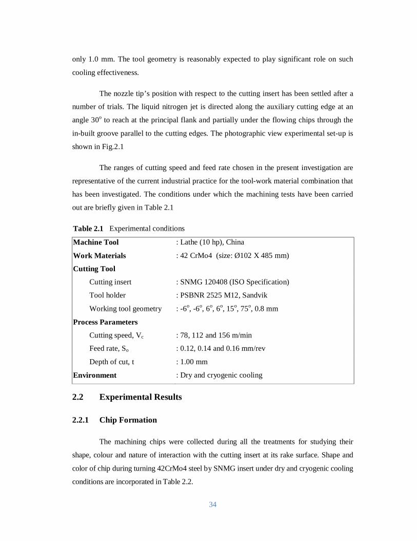
34
only 1.0 mm. The tool geometry is reasonably expected to play significant role on such
cooling effectiveness.
The nozzle tip’s position with respect to the cutting insert has been settled after a
number of trials. The liquid nitrogen jet is directed along the auxiliary cutting edge at an
angle 30o to reach at the principal flank and partially under the flowing chips through the
in-built groove parallel to the cutting edges. The photographic view experimental set-up is
shown in Fig.2.1
The ranges of cutting speed and feed rate chosen in the present investigation are
representative of the current industrial practice for the tool-work material combination that
has been investigated. The conditions under which the machining tests have been carried
out are briefly given in Table 2.1
Table 2.1 Experimental conditions
Machine Tool : Lathe (10 hp), China
Work Materials : 42 CrMo4 (size: Ø102 X 485 mm)
Cutting Tool
Cutting insert : SNMG 120408 (ISO Specification)
Tool holder : PSBNR 2525 M12, Sandvik
Working tool geometry : -6o, -6o, 6o, 6o, 15o, 75o, 0.8 mm
Process Parameters
Cutting speed, Vc : 78, 112 and 156 m/min
Feed rate, So : 0.12, 0.14 and 0.16 mm/rev
Depth of cut, t : 1.00 mm Environment : Dry and cryogenic cooling
2.2 Experimental Results
2.2.1 Chip Formation
The machining chips were collected during all the treatments for studying their
shape, colour and nature of interaction with the cutting insert at its rake surface. Shape and
color of chip during turning 42CrMo4 steel by SNMG insert under dry and cryogenic cooling
conditions are incorporated in Table 2.2.

35
Table 2.2 Shape and color of chips produced during turning 42CrMo4 steel by SNMG
insert under dry and cryogenic cooling conditions
Environment
Feed
(mm/rev)
Vc
(m/min)
Dry Cryogenic Cooling
Shape Colour Shape Colour
0.12
78 tubular blue tubular metallic
112 spiral blue tubular metallic
156 tubular blue tubular gray
0.14
78 tubular blue spiral metallic
112 tubular blue tubular metallic
156 tubular gray tubular metallic
0.16
78 tubular blue tubular metallic
112 tubular blue tubular metallic
156 tubular blue tubular gray
Fig.2.2 Schematic view of the formation of chip
The chip reduction coefficient, ξ (ratio of chip thickness after and before cut) is an
important index of chip formation and specific energy consumption for a given tool-work
combination. For specified tool geometry and cutting conditions, the value of chip
reduction coefficient depends upon the nature of chip-tool interaction, chip contact length,
curl radius and form of the chips all of which expected to be influenced by high-pressure
coolant in addition to the level of cutting speeds and feeds. In machining conventional
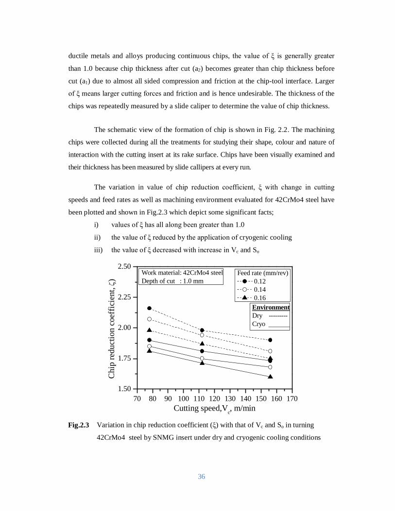
36
ductile metals and alloys producing continuous chips, the value of ξ is generally greater
than 1.0 because chip thickness after cut (a2) becomes greater than chip thickness before
cut (a1) due to almost all sided compression and friction at the chip-tool interface. Larger
of ξ means larger cutting forces and friction and is hence undesirable. The thickness of the
chips was repeatedly measured by a slide caliper to determine the value of chip thickness.
The schematic view of the formation of chip is shown in Fig. 2.2. The machining
chips were collected during all the treatments for studying their shape, colour and nature of
interaction with the cutting insert at its rake surface. Chips have been visually examined and
their thickness has been measured by slide callipers at every run.
The variation in value of chip reduction coefficient, ξ with change in cutting
speeds and feed rates as well as machining environment evaluated for 42CrMo4 steel have
been plotted and shown in Fig.2.3 which depict some significant facts;
i) values of ξ has all along been greater than 1.0
ii) the value of ξ reduced by the application of cryogenic cooling
iii) the value of ξ decreased with increase in Vc and So
70 80 90 100 110 120 130 140 150 160 1701.50
1.75
2.00
2.25
2.50
Chi
p re
duct
ion
coef
ficie
nt,
)
Cutting speed,Vc, m/min
Feed rate (mm/rev) 0.12 0.14 0.16
Work material: 42CrMo4 steelDepth of cut : 1.0 mm
EnvironmentDry ---------Cryo
Fig.2.3 Variation in chip reduction coefficient (ξ) with that of Vc and So in turning
42CrMo4 steel by SNMG insert under dry and cryogenic cooling conditions
37
Fig.2.3 clearly show that throughout the present experimental domain the value of
ξ gradually decreased with the increase in Vc though in different degree for the different
tool-work combinations, under both dry and cryogenic cooling conditions. The value of ξ
usually decreases with the increase in Vc particularly at its lower range due to
plasticization and shrinkage of the shear zone for reduction in friction and built-up edge
formation at the chip-tool interface due to increase in temperature and sliding velocity.
With the increase in feed (i.e. uncut chip thickness) also the value of ξ decreases due to
increase in effective rake angle of the tool with edge radiusing or beveling. In machining
steels by tools like carbide, usually the possibility of built-up edge formation and size and
strength of the built-up edge, if formed gradually increase with the increase in temperature
due to increase in Vc and also So and then decrease with the further increase in Vc due to
too much softening of the chip material and its removal by high sliding speed. Fig.2.3 is
showing how and to what extent ξ has decreased due to cryogenic cooling condition under
the different experimental conditions. With the increase in Vc and So, ξ increased as usual,
even under cryogenic cooling condition, due to increase in energy input.
2.2.2 Cutting Temperature
The specific energy required in machining converted into heat and the heat
generated during machining raises the temperature of the cutting tool tips and the work-
surface near the cutting zone.The machining temperature at the cutting zone is an
important index of machinability and needs to be controlled as far as possible. Cutting
temperature increases with the increase in specific energy consumption and material
removal rate (MRR). Such high cutting temperature adversely affects, directly and
indirectly, chip formation, cutting forces, tool life and dimensional accuracy and surface
integrity of the products.
Therefore, application of liquid nitrogen jet is expected to improve upon the
aforesaid machinability characteristics which play vital role on productivity, product
quality and overall economy. The lubricating effect on cutting temperatures in cryogenic
coolant machining is considered by the change of cutting forces which lead to different
heat intensities in the cutting zone. For the temperature rise in the chip on the tool-chip
interface, the effects of the shearing heat source on the shear plane and the frictional heat
source on the tool-chip interface are considered. For the temperature rise in the tool on the
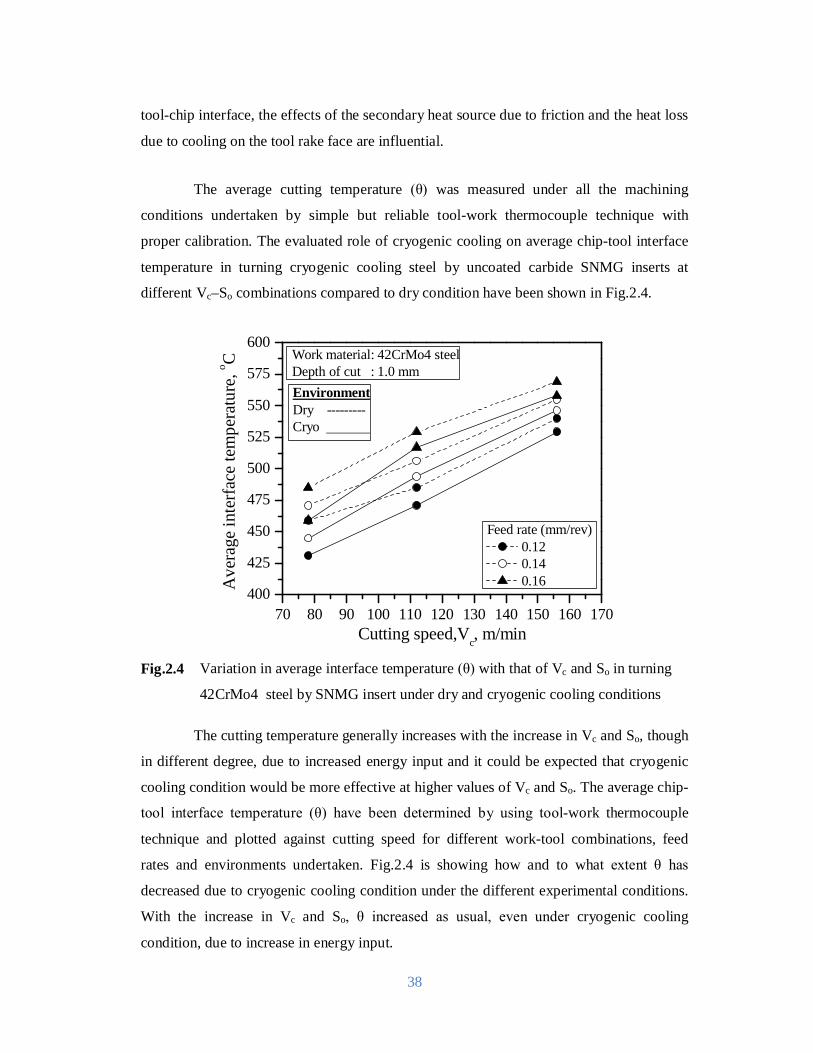
38
tool-chip interface, the effects of the secondary heat source due to friction and the heat loss
due to cooling on the tool rake face are influential.
The average cutting temperature (θ) was measured under all the machining
conditions undertaken by simple but reliable tool-work thermocouple technique with
proper calibration. The evaluated role of cryogenic cooling on average chip-tool interface
temperature in turning cryogenic cooling steel by uncoated carbide SNMG inserts at
different Vc–So combinations compared to dry condition have been shown in Fig.2.4.
70 80 90 100 110 120 130 140 150 160 170400
425
450
475
500
525
550
575
600
Ave
rage
inte
rfac
e te
mpe
ratu
re, o C
Cutting speed,Vc, m/min
Feed rate (mm/rev) 0.12 0.14 0.16
Work material: 42CrMo4 steelDepth of cut : 1.0 mmEnvironmentDry ---------Cryo
Fig.2.4 Variation in average interface temperature (θ) with that of Vc and So in turning
42CrMo4 steel by SNMG insert under dry and cryogenic cooling conditions
The cutting temperature generally increases with the increase in Vc and So, though
in different degree, due to increased energy input and it could be expected that cryogenic
cooling condition would be more effective at higher values of Vc and So. The average chip-
tool interface temperature (θ) have been determined by using tool-work thermocouple
technique and plotted against cutting speed for different work-tool combinations, feed
rates and environments undertaken. Fig.2.4 is showing how and to what extent θ has
decreased due to cryogenic cooling condition under the different experimental conditions.
With the increase in Vc and So, θ increased as usual, even under cryogenic cooling
condition, due to increase in energy input.
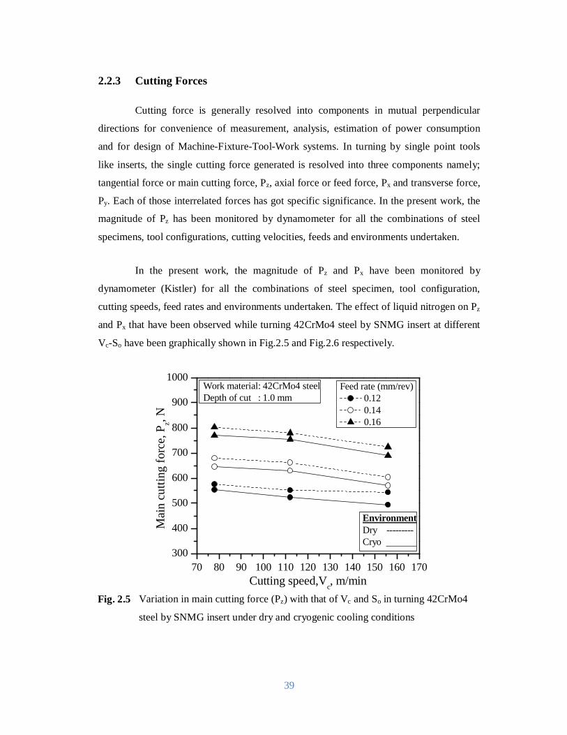
39
2.2.3 Cutting Forces
Cutting force is generally resolved into components in mutual perpendicular
directions for convenience of measurement, analysis, estimation of power consumption
and for design of Machine-Fixture-Tool-Work systems. In turning by single point tools
like inserts, the single cutting force generated is resolved into three components namely;
tangential force or main cutting force, Pz, axial force or feed force, Px and transverse force,
Py. Each of those interrelated forces has got specific significance. In the present work, the
magnitude of Pz has been monitored by dynamometer for all the combinations of steel
specimens, tool configurations, cutting velocities, feeds and environments undertaken.
In the present work, the magnitude of Pz and Px have been monitored by
dynamometer (Kistler) for all the combinations of steel specimen, tool configuration,
cutting speeds, feed rates and environments undertaken. The effect of liquid nitrogen on Pz
and Px that have been observed while turning 42CrMo4 steel by SNMG insert at different
Vc-So have been graphically shown in Fig.2.5 and Fig.2.6 respectively.
70 80 90 100 110 120 130 140 150 160 170300
400
500
600
700
800
900
1000
Mai
n cu
tting
forc
e, P
z, N
Cutting speed,Vc, m/min
Feed rate (mm/rev) 0.12 0.14 0.16
Work material: 42CrMo4 steelDepth of cut : 1.0 mm
EnvironmentDry ---------Cryo
Fig. 2.5 Variation in main cutting force (Pz) with that of Vc and So in turning 42CrMo4
steel by SNMG insert under dry and cryogenic cooling conditions
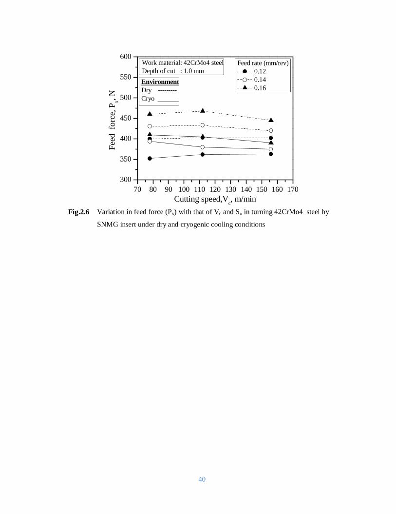
40
70 80 90 100 110 120 130 140 150 160 170300
350
400
450
500
550
600
Feed
for
ce, P
x, N
Cutting speed,Vc, m/min
Feed rate (mm/rev) 0.12 0.14 0.16
Work material: 42CrMo4 steelDepth of cut : 1.0 mmEnvironmentDry ---------Cryo
Fig.2.6 Variation in feed force (Px) with that of Vc and So in turning 42CrMo4 steel by
SNMG insert under dry and cryogenic cooling conditions
41
Chapter-3
Modeling of Cutting Temperature The increasing customer needs for higher quality enlarge the significance of
precision machining. It is a relatively new area of machine industry and requires intensive
experimental and practical investigation activity referring to technological parameters and
circumstances. One part of the research activity of our department is the scope of precision
machining and the applicability of our results in the industry. The monitoring of cutting
processes predestinates the investigation on the major technological variables determining
the shape and dimensional accuracy of the machined parts. Among several influences
cutting temperature plays an important role in metal cutting. Machining is inherently
characterized by generation of heat and high cutting temperature. At such elevated
temperature the cutting tool if not enough hot hard may lose their form stability quickly or
wear out rapidly resulting in increased cutting forces, dimensional inaccuracy of the
product and shorter tool life. The magnitude of this cutting temperature increases, though
in different degree, with the increase of cutting velocity, feed and depth of cut and as a
result, high production machining is constrained by rise in temperature. This problem
increases further with the increase in strength and hardness of the work material. Normally
the heat is produced for several reasons.
3.1 Temperature Rise due to Heat Source
If a certain amount of heat is suddenly liberated in unit area of a plane surface in a
body, this surface becomes an instantaneous source of heat. If the heat is developed
continuously instead of suddenly it is known as continuous source. The rate of heat release
in continuous source may be constant or may be a function of time expressible as φ (T).
Furthermore the heat sources may be known a point, line, plane or cylindrical
source. Another is moving source of heat.

42
Fourier equation of conduction of heat is given by
+ + = ……………………………………………….. [3.1]
The equation is satisfied by a solution of the type,
휃 =( ) ⁄ exp …………………………… [3.2]
This equation can be extended for any type of heat source. For a continuous point
source, when heat is liberated at the rate φ (T), pc per unit time, from 푇 = 0 to 푇 = 푇 ′at
the location푥 ′,푦 ′, 푧′, the temperature rise at 푥,푦, 푧at time 푇 is
휃 =( )
∫ ∅(푇′)푒 { ( )}⁄( ) ⁄ …………………………….. [3.3]
where
휃 = Temperature at any location 푥 ,푦 , 푧 oC, 푞 = Strength of an instantaneous point source of heat liberated at 푥 ,푦 , 푧 at
T=0 Total quantity of heat liberated at 푇 = 0 at 푥 ,푦 ,푧 is 푞푝푐 훿 = thermal diffusivity = cm2/second
in which
휆 = thermal conductivity (cal/cm/second/oC)
휌푐 = volume specific heat (cal/oC/cm3)
where 푟 = (푥 − 푥′) + (푦 − 푦′) + (푧 − 푧′)
If the rate of heat liberation is constant then
휃 =( )
∫ ∅(푇′)푒 { ( )}⁄( ) ⁄ ………………………… [3.4]
where T = (T − T′)
hence θ = erfc( )
For a steady state distribution, when푇 → ∞,
θ = ……………………………………………………………… [3.5]

43
(a)
(b)
Fig. 3.1 Schematic view of (a) the frictional heat source at chip tool interface (b) the frictional heat source at chip tool interface considering as a stationary rectangular heat source
For a continuous moving point source of heat when the heat is liberated at the rate
of q cal/second at 푥,푦, 푧 = 0 for a time 푑푇′and an infinite slider moves past this source
with a velocity V parallel to axis, the temperature at a point 푥, 푦, 푧 at time T can be
calculated from
dθ =[ ( )] ⁄ exp { ( )}
( )…….…………………. [3.6]
Hence the temperature liberation between the period 0 and T is
θ =
1
8ρc(πδ)
e(T − T ) ⁄ dT
= ⁄ e ⁄ ∫ e∞( ) dξ…………………
[3.7]
where R = x + y + z
For steady state solutionT → ∞,
θ = e ( )/( )……………………………………………… [3.8]
For a linear source when the heat of emitted at the rate of q’ per unit length along
y axis and per unit length, and the temperature at the surface (푧 = 0) is sought. The upper
equation when integrated along y between −∞to∞ provides the solution
θ = e ⁄ K …………………………………………………. [3.9]
where K (X) is modified Bessel function of second kind of order zero,X =
Jaegar and Blok have derived out the solution for an infinite strip source−l < x < l,
−∞ < y < ∞ the surface z=0, when heat flux is q cal/cm2 /second and the surrounding
medium moves a velocity in the direction of x.
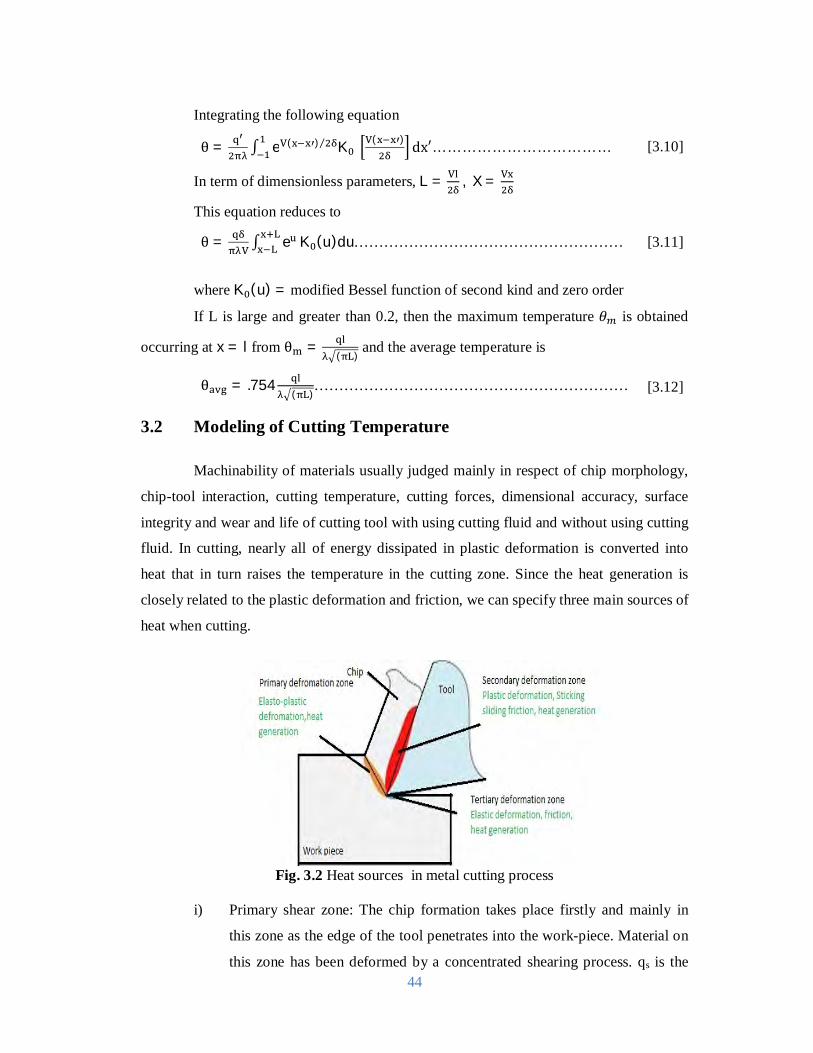
44
Integrating the following equation
θ = ∫ e ( )⁄ K ( ) dx′……………………………… [3.10]
In term of dimensionless parameters, L = , X =
This equation reduces to
θ = ∫ e K (u)du……………………………………………… [3.11]
whereK (u) = modified Bessel function of second kind and zero order
If L is large and greater than 0.2, then the maximum temperature 휃 is obtained
occurring at x = l from θ =( )
and the average temperature is
θ = .754( )
……………………………………………………… [3.12]
3.2 Modeling of Cutting Temperature
Machinability of materials usually judged mainly in respect of chip morphology,
chip-tool interaction, cutting temperature, cutting forces, dimensional accuracy, surface
integrity and wear and life of cutting tool with using cutting fluid and without using cutting
fluid. In cutting, nearly all of energy dissipated in plastic deformation is converted into
heat that in turn raises the temperature in the cutting zone. Since the heat generation is
closely related to the plastic deformation and friction, we can specify three main sources of
heat when cutting.
Fig. 3.2 Heat sources in metal cutting process
i) Primary shear zone: The chip formation takes place firstly and mainly in
this zone as the edge of the tool penetrates into the work-piece. Material on
this zone has been deformed by a concentrated shearing process. qs is the
45
heat, generated in the primary zone due to intensive plastic deformation.
The shear plane temperature is very important because it influences flow
stress of work piece material and temperatures on the tool face. In this area
local heating due to plastic work can cause the temperature to become very
high. This leads to softening of the material and allows greater deformation
and further heating, which can lead to periodic shear band formation and
serrated chips.
ii) Secondary shear zone: The chip and the rake face of the tool are in contact.
When the frictional stress on the rake face reaches a value equal to the shear
yield stress of the work-piece material, material flow also occur on this
zone. Frictional heat source qf localizes at the tool-chip interface heat
source. The friction in this area causes generation of heat, which can lead to
high temperatures. Temperature of rake face is the maximum temperature in
real machining operations and it causes tool wear.
iii) Tertiary shear zone: When the clearance face of the tool rubs the newly
machined surface deformation can occur on this zone. Heat source qr is
generated due to tip radius of the cutting tool. The surface roughness and
integrity of the finished surface, produced by the cutting process, are of
interest in this area.
The main assumptions employed in the model development are:
i) The cutting edge is assumed to be sharp so that the tertiary zone can be
neglected.
ii) All energy involved in plastic deformation (in the shear zone and at the
chip-tool interface) is converted into heat.
iii) The primary and secondary zones are plane surfaces.
iv) The heat generated along the friction interface and the heat generated along
the shear zone is evenly distributed.
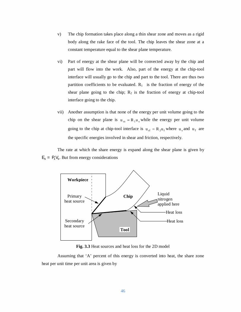
46
v) The chip formation takes place along a thin shear zone and moves as a rigid
body along the rake face of the tool. The chip leaves the shear zone at a
constant temperature equal to the shear plane temperature.
vi) Part of energy at the shear plane will be convected away by the chip and
part will flow into the work. Also, part of the energy at the chip-tool
interface will usually go to the chip and part to the tool. There are thus two
partition coefficients to be evaluated. R1 is the fraction of energy of the
shear plane going to the chip; R2 is the fraction of energy at chip-tool
interface going to the chip.
vii) Another assumption is that none of the energy per unit volume going to the
chip on the shear plane is s1cs uRu while the energy per unit volume
going to the chip at chip-tool interface is f2cf uRu where su and fu are
the specific energies involved in shear and friction, respectively.
The rate at which the share energy is expand along the shear plane is given by
E = P V . But from energy considerations
Fig. 3.3 Heat sources and heat loss for the 2D model
Assuming that ‘A’ percent of this energy is converted into heat, the share zone
heat per unit time per unit area is given by
Heat loss
Heat loss
Primary heat source
Secondary heat source
Workpiece
Chip Liquid nitrogen applied here
Tool

47
푞 =
Cal/cm2/second.…………………………………….. [3.14]
where 푎 , b1 are in cm and, A= 0.98 to 1.0
Part of the heat will travel with the chip 푐 푞 and rest of them (1 − c q ) will
flow back to the work piece. Total shear heat 푐 푞 going to chip will be
Ac [ ]
While the heat is utilized in raising the temperature of the chip, when
Ac [ ] = cp ρ V a b [θ − θ ]……………………………….. [3.15]
J= mechanical equivalent of heat in kg.cm/cal
A= 0.98 to 1.0
cp ρ =Volumetric specific heat of chip material at shear zone temperature,
cal/cm3/0c
Hence
θ = Ac [ ] + θ …………………………………………….. [3.16]
where, θ = Ambient temperature in 0C
Fig. 3.4 Moving of source of shear plane
Tool
Chip
Vs
푏 푎

48
when
θ =
. ( )
( )……………………………………………. [3.17]
From 3.16 and 3.17 푐 =.
and
L = = ……………………………………………….. [3.18]
In which δ is the thermal diffusivity of conducting surface in cm2/second.
Equating the both equation
θ = ( )
[ . ]+ θ ………………………………… [3.19]
In an infinites solid initially at zero temperature, the temperature rise at the joint
푥, 푦, 푧 at time T due to a quantity of heat q instantaneously liberated at 푥 ,푦 , 푧 at zero time
is given by the equation
∆θ =( ) ⁄ exp ( ) ( ) ( ) …………………………. [3.20]
For the case of a continuous heat source extending over a finite area and for a
steady state condition (T → ∞) the equation for the rise of temperature due to a uniform
heat source extending over −l < x < land − m < y′ < m as shown in the following
figure
∆θ , , = ∫ dx′∫ ′[( ′) ( ′) ]
………………………….. [3.21]
Fig.3.5 Stationary source of heat at chip tool interface

49
Hence
∆θ = (x + l) sinh − sinh + (x − l) sinh −
sinh + (y + m) sinh − sinh + (y−
m) sinh − sinh …
[3.22]
The mean temperature rise is
∆θi|avg = ∫ ∫ (∆ ) , , = ………………… [3.23]
where
A =2π sinh
ml +
ml sinh
lm +
13
ml +
13
lm
−13
lm +
ml 1 +
ml
For a cutting edge extending from−∞푡표∞; free cutting similar to orthogonal
pipe turning where length of cutting edge is quite large compared to width of cut takes
place when
퐥
= ………………………………………………………………….. [3.24]
where,
t = Depth of cut
l=Cn = Natural contact length, mm
For a cutting edge extending from−∞to∞; such as in ‘restricted’ cutting in
conventional turning:
퐥
= ……………………………………………………………………. [3.25]
The heat liberated at the interface is given by
q = ……………………………………………………………….. [3.26]

50
The amount of this heat going to the chip is c q and heat going to the tool is
(1 − c )q . Again, utilizing Jaeger’s moving source of heat equation from previous
θ = .754( )
…..………………………………………………… [3.27]
whereL =⁄
and,
λ ,δ = thermal conductivity and thermal diffusivity at interface temperature of chip material.
θ = θ + .( )
……..………………………………………………. [3.28]
But from the previous equation θ = θ + ( ) A
and,
λ = thermal conductivity of tool at interface temperature.
Equating the both equation
c = .
( )
…………...……………………………………….. [3.29]
It can be shown:
E = τ ε E = μτ
ξsinβ
Analytically the effect of cryogenic on cutting speed, feed rate is
Effectθi(cryo) =1.5푏1
푎1휉
1+푎2휉푣푐
+ 2.27
(푣푐푆표푠푖푛휑+1.328)(1+푎2휉푣푐
)............................................
[3.30]
The effect of cryogenic cooling condition in the following equation is when Vc is
increasing then 휉 is decreasing a large amount so the factor a2ξVc
is decreasing and finally
the factor 1.5b1
a1ξ
1+ a2ξVc
is increasing. Again with increasing Vc, (V S sinφ + 1.328) factor is
increasing. So 2.27
(VcSosinφ+1.328)(1+a2ξVc
)factors will decrease, as the effect of (V S sinφ +
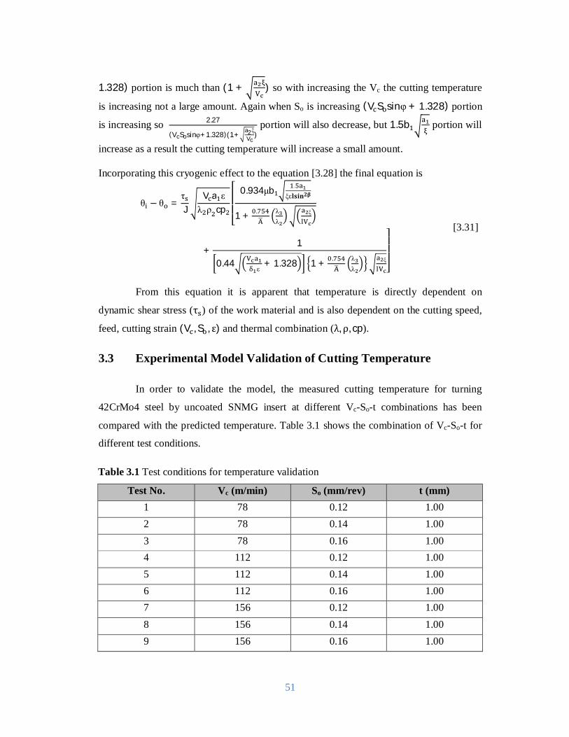
51
1.328) portion is much than (1 + ) so with increasing the Vc the cutting temperature
is increasing not a large amount. Again when So is increasing (V S sinφ + 1.328) portion
is increasing so 2.27
(VcSosinφ+1.328)(1+a2ξVc
) portion will also decrease, but 1.5b portion will
increase as a result the cutting temperature will increase a small amount. Incorporating this cryogenic effect to the equation [3.28] the final equation is
θ − θ =τJ
V a ελ ρ cp
⎣⎢⎢⎢⎡ 0.934μb .
ξε퐥퐬퐢퐧ퟐ훃
1 + . λλ
ξ
+1
0.44 δ ε+ 1.328 1 + . λ
λξ
⎦⎥⎥⎥⎤
[3.31]
From this equation it is apparent that temperature is directly dependent on
dynamic shear stress (τ ) of the work material and is also dependent on the cutting speed,
feed, cutting strain (V , S , ε)and thermal combination (λ, ρ, cp).
3.3 Experimental Model Validation of Cutting Temperature
In order to validate the model, the measured cutting temperature for turning
42CrMo4 steel by uncoated SNMG insert at different Vc-So-t combinations has been
compared with the predicted temperature. Table 3.1 shows the combination of Vc-So-t for
different test conditions.
Table 3.1 Test conditions for temperature validation
Test No. Vc (m/min) So (mm/rev) t (mm) 1 78 0.12 1.00 2 78 0.14 1.00 3 78 0.16 1.00 4 112 0.12 1.00 5 112 0.14 1.00 6 112 0.16 1.00 7 156 0.12 1.00 8 156 0.14 1.00 9 156 0.16 1.00

52
In the Fig 3.5 predicted values from the analytical model and the measured values
have been compared. It shows that the predicted values can follow the trend of the
measured values very efficiently and can predict the value of the cutting temperature
within reasonable error level.
0 2 4 6 8 10300
400
500
600
700
800
Chi
p to
ol in
terf
ace
tem
pera
ture
, o C
Test number
Work material: 42CrMo4 steelDepth of cut : 1.0 mmExperimental Value ---------Predicted Value
Feed Rate (mm/rev) 0.12 0.14 0.16
Fig.3.6 Comparison of actual and predicted cutting temperature for different
combinations of cutting velocity and feed rate under cryogenic condition.
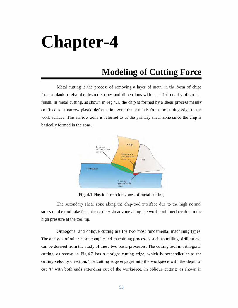
53
Metal cutting is the process of removing a layer of metal in the form of chips
from a blank to give the desired shapes and dimensions with specified quality of surface
finish. In metal cutting, as shown in Fig.4.1, the chip is formed by a shear process mainly
confined to a narrow plastic deformation zone that extends from the cutting edge to the
work surface. This narrow zone is referred to as the primary shear zone since the chip is
basically formed in the zone.
Fig. 4.1 Plastic formation zones of metal cutting
The secondary shear zone along the chip-tool interface due to the high normal
stress on the tool rake face; the tertiary shear zone along the work-tool interface due to the
high pressure at the tool tip.
Orthogonal and oblique cutting are the two most fundamental machining types.
The analysis of other more complicated machining processes such as milling, drilling etc.
can be derived from the study of these two basic processes. The cutting tool in orthogonal
cutting, as shown in Fig.4.2 has a straight cutting edge, which is perpendicular to the
cutting velocity direction. The cutting edge engages into the workpiece with the depth of
cut "t" with both ends extending out of the workpiece. In oblique cutting, as shown in
Chapter-4
Modeling of Cutting Force
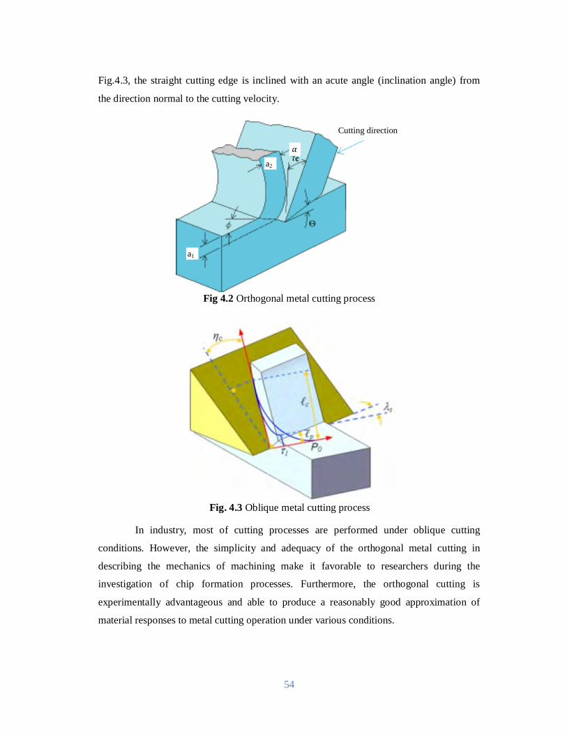
54
Fig.4.3, the straight cutting edge is inclined with an acute angle (inclination angle) from
the direction normal to the cutting velocity.
Fig 4.2 Orthogonal metal cutting process
Fig. 4.3 Oblique metal cutting process
In industry, most of cutting processes are performed under oblique cutting
conditions. However, the simplicity and adequacy of the orthogonal metal cutting in
describing the mechanics of machining make it favorable to researchers during the
investigation of chip formation processes. Furthermore, the orthogonal cutting is
experimentally advantageous and able to produce a reasonably good approximation of
material responses to metal cutting operation under various conditions.
a1
Cutting direction
훼
a2

55
4.1 Thin Shear Plane and Thick Deformation Zone Model
Piispanen's work, first published in 1937 and published in English in [1948],
applied 'pack of cards' analogy to explain the deformation pattern during chip formation
process.
As shown in Fig.4.4, the chip formation process is represented by a deck of cards
inclined to the cutting direction with an angle∅. As the tool moves relative to the
workpiece, it engages one card at a time and causes it to slide over its neighbor. Each chip
segment (each card) is represented by a small thin parallelogram. Slipping occurs between
each chip segment along the shear plane. The assumption and simplifications of the card
model can be summarized as:
i) Shear action occurs on a perfectly plane surface.
ii) Exaggerates the in homogeneity of strain.
iii) Does not account for the chip curl.
iv) Assumes no BUE formation.
v) Interprets the tool face friction as elastic rather than plastic.
Fig.4.4
Deck-of-Cards chip formation model (a) Parallel shear plate (b) Thickness plate (c) Relation of angle [Piispanen1948]
In spite of the simplicity, limitations, and assumptions, this analogy of the chip
formation process presents a good illustration of how the shearing action occurs.

56
The first quantitative analysis of the cutting forces based on the upper bound
theory was made by Merchant [1945]. It was assumed that the chip of the rigid perfectly
plastic material is formed as a result of the intensive shearing along a thin shear plane,
which forms an angle ∅with the cutting tool moving direction. The first and the most
remarkable contribution from Merchant’s analysis is that the geometrical relationships
among the various pairs of perpendicular force components are defined in a circle with the
diameter representing the resultant force R, as shown in Fig.4.5. The force components at
the shear plane (Ps and Pn), the friction force and normal force at the chip-tool interface (F
and N), the main cutting force (Pz) and thrust force (Py) can be related through the shear
angle ∅ , the tool rake angle 훼 and the friction angle 훽 as shown.
Fig. 4.5 Merchant’s Shear plane force circle
The second contribution is that the shear angle ∅is determined in terms of the
rake angle 훼and the friction angleβ by minimizing the energy consumption during the
cutting process.
If the shear stress 휏at the shear plane and the friction angle훽 at the chip-tool
interface are known, with the given tool geometry and cutting conditions, the orthogonal
cutting forces can be predicted.
The third contribution is the hodograph obtained based on the upper bound
analysis. The assumption that all the deformation takes place at a single shear plane across
β
푎
푎
P
퐏퐧퐏퐳
퐏퐱퐲

57
which the work material turns into the chip, leads to the hodograph shown in the Figure 4.
It can be seen that the work material with the initial cutting velocity U suddenly changes to
the chip with the velocity Vc. This sudden change of the velocity produces a velocity
discontinuity along the shear plane, the so-called shear velocity Vs. With this hodograph,
the chip velocity and the shear velocity are able to be related to the known cutting velocity.
P = P cos∅ − P sin∅……………………………………………. [4.1]
P = Rsin(∅ + β − α)….……………………………………………… [4.2]
R =(∅ )
….……………………………………………………… [4.3]
F= Rsinβ….………………………………………………………….. [4.4]
N = Rcosβ….………………………………………………………….. [4.5]
P = Rcos(β − α)….…………………………………………………... [4.6]
P = Rsin(β − α)….…………………………………………………... [4.7]
∅ = − (β − α)….…………………………………………………... [4.8]
V = ∅(∅ )
………..…………………………………………………. [4.9]
V =(∅ )
………………………………………………..................... [4.10]
So the co-efficient of friction is can be calculated according to equation 4.11
휇 = = = ηtan ………………………………
[4.11]
The force circle, the shear angle equation and the hodograph have been serving as
the foundation for the machining process research since then. The major limitations of
Merchant’s analysis are:

58
i) The material is assumed to be rigid perfectly plastic, so that the effects of
the strain, strain rate and the temperature are not considered.
ii) The shear strain rate along the shear plane is infinite due to the sudden
change of the velocity across the infinitely thin shear plane.
iii) During the derivation of the shear angle relation, the shear angle was
isolated as a constant so that the interrelations among the shear angle and
other processing parameters were not taken into account.
iv) The force circle, the shear angle equation and the hodograph have been
serving as the foundation for the machining process research since then.
Lee and Shaffer [1951] introduced the slip-line field analysis dealing with the
plane plastic flow problems in the plasticity theory into the area of metal cutting based on
the following assumptions:
i) The work material is rigid perfectly plastic, meaning that during the
deforming process, plastic strain overwhelmingly dominates and that the
shear flow stress is invariant throughout the deformation zone.
ii) The deformation rate has no influence on the material behavior.
iii) The effect of temperature increase during deformation is negligible.
iv) The inertia effect as a result of material acceleration during deformation is
neglected.
Under these assumptions, Lee and Shaffer constructed a slip line field that
consists of two orthogonal classes of so-called slip lines, indicating the two orthogonal
maximum shear stress directions at the specific point in the plastic deformation zone, as
shown in Fig.4.6. The lower boundary of the field is formed by an idealized shear plane
AC, extending from the tool cutting edge to the point where the chip and work material
free surface intersect, and all the deformation is assumed to take place at this plane. It can
be easily realized that this shear plane is very similar to that in Merchan’s analysis. Since
AC is the direction of the maximum shear stress, a line AB on which the shear stress is
zero is constructed along the direction 45 degree away from AC, and it serves as the upper
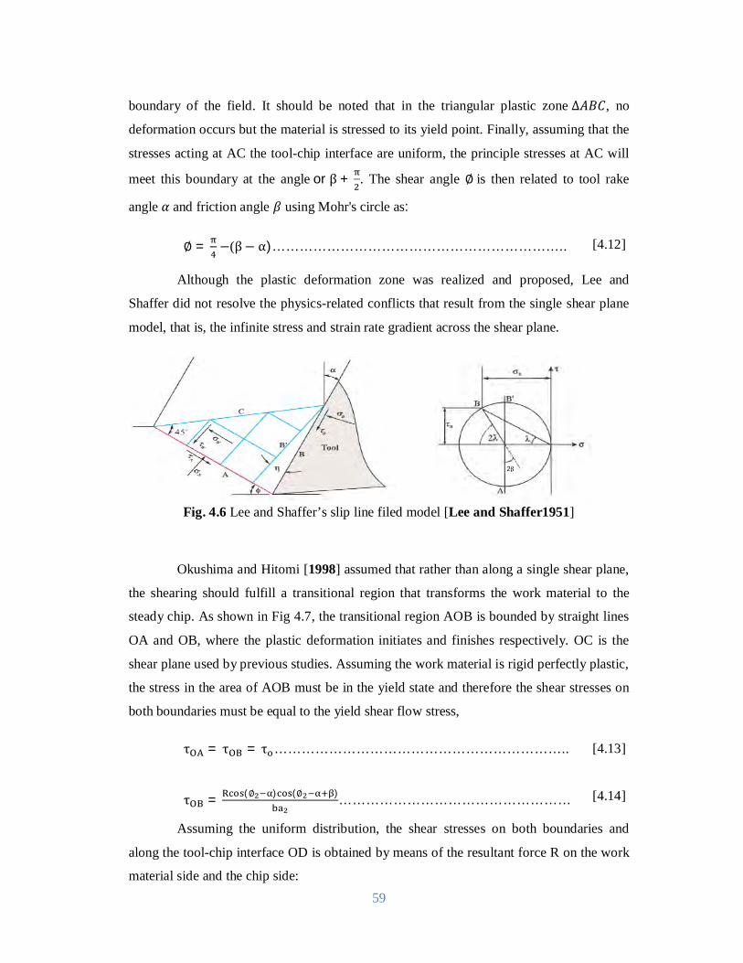
59
boundary of the field. It should be noted that in the triangular plastic zone∆퐴퐵퐶, no
deformation occurs but the material is stressed to its yield point. Finally, assuming that the
stresses acting at AC the tool-chip interface are uniform, the principle stresses at AC will
meet this boundary at the angleorβ + . The shear angle ∅is then related to tool rake
angle훼and friction angle 훽using Mohr's circle as:
∅ = −(β− α)……………………………………………………….. [4.12]
Although the plastic deformation zone was realized and proposed, Lee and
Shaffer did not resolve the physics-related conflicts that result from the single shear plane
model, that is, the infinite stress and strain rate gradient across the shear plane.
Fig. 4.6 Lee and Shaffer’s slip line filed model [Lee and Shaffer1951]
Okushima and Hitomi [1998] assumed that rather than along a single shear plane,
the shearing should fulfill a transitional region that transforms the work material to the
steady chip. As shown in Fig 4.7, the transitional region AOB is bounded by straight lines
OA and OB, where the plastic deformation initiates and finishes respectively. OC is the
shear plane used by previous studies. Assuming the work material is rigid perfectly plastic,
the stress in the area of AOB must be in the yield state and therefore the shear stresses on
both boundaries must be equal to the yield shear flow stress,
τ = τ = τ ……………………………………………………….. [4.13]
τ = (∅ ) (∅ )…………………………………………… [4.14]
Assuming the uniform distribution, the shear stresses on both boundaries and
along the tool-chip interface OD is obtained by means of the resultant force R on the work
material side and the chip side:
2β

60
휏 = (∅ ) (∅ )……………………………….…… [4.15]
τ = (∅ ) (∅ )………………………….………… [4.16]
τ = = τ …………………………………...……………… [4.17]
Where ∅ and ∅ are the inclination angles of the lower boundary and upper
boundary of the shear zone to the cutting direction. βis the mean friction angle, is 푙the
contact length of the tool-chip interface a and a are the uncut chip thickness and
deformed chip thickness respectively.
Equating equations, the inclination angles of lower boundary and upper boundary
can be determined.
∅ = − + …………………………………………………………. [4.18]
∅ = − + …………………………………………………………. [4.19]
K = sin + sin(β − α) …..………………………………… [4.20]
K = sin + cosβ ……………………………………………. [4.21]
From the geometry, the shear strain inside the shear zone at any given transitional
line can be expressed as follows:
ε = = cot∅ − cot(∅ − α )……………………………………… [4.22]
Where ∅ the inclination is angle of the arbitrary radial plane, and isѰ formed by
the tangential to the point of interest on the free surface and the cutting direction. In
particular, the shear strain on the starting and ending boundary lines of flow region are
given by:
ε = ε = cot∅ − tan(∅ − α)……………………………………... [4.23]

61
Fig.4.7 Okushima and Hitomi's model
The most distinguished contribution from this work is the gradual change of the
shear strain, although in a discrete manner, can be expressed in terms of the tool rake angle
and the average friction angle. However, the effect of work hardening and the thermal
softening are still excluded.
Considering the fact that each plastic deformation is caused by shear and
therefore characterized by lines of maximum shear stress (slip lines), Zorev [1996]
depicted the shape of the deformation zone with the basic knowledge of plasticity.
Fig. 4.8 Zorev's schematic representation of slip lines in chip formation [Zorev1998]
As shown in Fig.4.8, since LM is the free surface and slip lines stands for the
planes of maximum shear stress, each slip line should meet the free surface with an equal
angle of . To satisfy this boundary condition, these lines must be curved instead of
straight. For example, if line OL is straight, it would form an angle smaller than with the
free surface. Furthermore, there must be a deformation zone (the dotted lines) around point
O to initiate the deformation. The most part of this zone is on the chip-tool interface and
푎
푎
푃
푃
Tool Work
Chip
Flow region
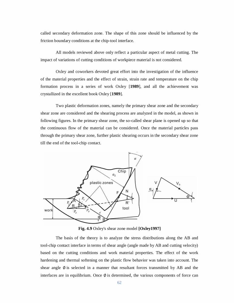
62
called secondary deformation zone. The shape of this zone should be influenced by the
friction boundary conditions at the chip-tool interface.
All models reviewed above only reflect a particular aspect of metal cutting. The
impact of variations of cutting conditions of workpiece material is not considered.
Oxley and coworkers devoted great effort into the investigation of the influence
of the material properties and the effect of strain, strain rate and temperature on the chip
formation process in a series of work Oxley [1989], and all the achievement was
crystallized in the excellent book Oxley [1989].
Two plastic deformation zones, namely the primary shear zone and the secondary
shear zone are considered and the shearing process are analyzed in the model, as shown in
following figures. In the primary shear zone, the so-called shear plane is opened up so that
the continuous flow of the material can be considered. Once the material particles pass
through the primary shear zone, further plastic shearing occurs in the secondary shear zone
till the end of the tool-chip contact.
Fig. 4.9 Oxley's shear zone model [Oxley1997]
The basis of the theory is to analyze the stress distributions along the AB and
tool-chip contact interface in terms of shear angle (angle made by AB and cutting velocity)
based on the cutting conditions and work material properties. The effect of the work
hardening and thermal softening on the plastic flow behavior was taken into account. The
shear angle ∅is selected in a manner that resultant forces transmitted by AB and the
interfaces are in equilibrium. Once ∅is determined, the various components of force can
푃
푃
푃
푃
푎
훼
63
be determined from geometry relations. The most significant contribution is that Oxley and
co-workers used the velocity modified temperature concept to describe material properties
as a function of strain rate and temperature. The velocity modified temperature, defined
asT = T 1 − vlg ̇̇increases as the temperature increases and decreases as the
strain rate increases. The parameters 푣 and휀̇ are the constants for a given material. The
flow stress is related to the strain through the power lawσ = σ (T )ε ( ), where
both strength coefficient and the strain hardening exponent, are functions of velocity
modified temperature. The detailed demonstration of the methodology will be introduced
later. The following is the list of assumptions and limitations in the Oxley's model:
i) The shear strain rate is constant through the shear zone.
ii) The shear stress is constant along shear plane AB.
iii) Half of the overall shear strain occurs at AB.
iv) The effect of temperature gradient is neglected.
v) The effect of strain rate gradient is neglected.
vi) The distribution of the hydrostatic pressure alone AB is linear with A B P.
vii) The distribution of normal stress at chip-tool rake interface is uniform.
viii) The shear stress along chip-tool rake interface is constant.
ix) Sticking dominates in secondary shear zone and the shear strength in the
chip material adjacent to the tool-chip interface will be used to represent the
friction parameter.
x) The hodograph is adopted from that for single shear plane model so that
velocity discontinuity still exists.
Although sweeping assumptions and simplifications were utilized, Oxley's
machining theory still serve as a great breakthrough toward the understanding of the
machining process.
4.2 Modeling of Cutting Forces
The knowledge of cutting forces developing in the various machining processes
under given cutting factors is of great importance, being a dominating criterion of material
machinability, to both: the designer-manufacturer of machine tools, as well as to user.
Also, their prediction helps in the analysis of optimization problems in machining
64
economics, in adaptive control applications, in the formulation of simulation models used
in cutting databases. In this regard, cutting forces being a substantial dependent variable of
the machining system has been tested by many researchers in various cutting processes
through formulation of appropriate models for their estimation. These are analytical, semi-
empirical and empirical relationships, which connect cutting factors to forces.
Over the last years, empirical models for the machinability parameters in various
machining processes have been developed using data mining techniques, such as statistical
design of experiments, computational neural networks and genetic algorithms. These
techniques possess the advantage of providing the impact of each individual factor and
factor interactions, after an appropriate design of the experiment. Mainly, for the Taguchi
and response surface methodology, a minimum amount of experimental trials is combined
to a reliable global examination of the variables interconnection, instead of one factor at a
time experimental approach and analysis.
The response surface methodology (RSM) is a collection of mathematical and
statistical techniques useful for the modeling and analysis of problems in which a response
of interest is influenced by several variables and the objective is to optimize this response
[Montgomery 2005]. The most extensive applications of RSM are in the particular
situations where several input variables potentially influence some performance measure
or quality characteristic of the process. The performance measure or quality characteristic
is called the response. The input variables are sometimes called independent variables. The
field of response surface methodology consists of the experimental strategy for exploring
the space of the process or independent variables, empirical statistical modeling to develop
an appropriate approximating relationship between the yield and the process variables, and
optimization methods for finding the values of the process variables that produce desirable
values of the response. In this work we will concentrate on the second strategy: statistical
modeling to develop an appropriate approximating model between. The concept of the
response surface involves a dependent variable (Y) called the response variable and
several independent variables Xo, X1, X2, X3 ….Xn. If all of these variables are assumed
to be measurable, the response surface can be expressed as follow
e....XX,X,X,XfY n321o …………………………………………. [4.24]
65
Where, f is the response function which is unknown and perhaps very
complicated and ‘e’ is the error which is normally distributed with zero mean according to
the observed response. It is assumed that the independent variables are continuous and
controllable by the experimenter with negligible error. Usually they are called the natural
variables, because they are expressed in the natural units of measurement, such as degrees
Celsius, pounds per square inch, etc. In much RSM work it is convenient to transform the
natural variables to coded variables, which are usually defined to be dimensionless with
mean zero and the same standard deviation.
Because the form of the true response function f is unknown, we must
approximate it. In fact, successful use of RSM is critically dependent upon the
experimenter’s ability to develop a suitable approximation for f. In many cases, either a
first-order or a second order model is used.
The first-order model is likely to be appropriate when the experimenter is
interested in approximating the true response surface over a relatively small region of the
independent variable space in a location where there is little curvature in f. The form of the
first-order model in the following equation is sometimes called a main effects model,
because it includes only the main effects of the variables.
e....XbXbXbXb Y 332211oo …………………………….. [4.25]
If there is an interaction between these variables, it can be added to the model
easily as follows:
e
........XXbXXbXXbXbXbXbXb
Y31133223
2112332211oo
……………………… [4.26]
This is the first-order model with interaction. Adding the interaction term
introduces curvature into the response function. Often the curvature in the true response
surface is strong enough that the first-order model (even with the interaction term
included) is inadequate. A second-order model will likely be required in these situations.
The general second-order model is as given below:
e
........XbXbXbXXb
XXbXXbXbXbXbXbY 2
3332222
21113113
32232112332211oo
………
[4.27]
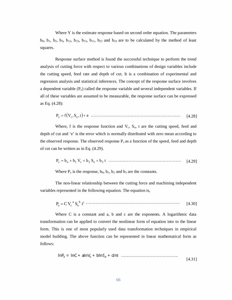
66
Where Y is the estimate response based on second order equation. The parameters
b0, b1, b2, b3, b12, b23, b13, b11, b22 and b33 are to be calculated by the method of least
squares.
Response surface method is found the successful technique to perform the trend
analysis of cutting force with respect to various combinations of design variables include
the cutting speed, feed rate and depth of cut. It is a combination of experimental and
regression analysis and statistical inferences. The concept of the response surface involves
a dependent variable (Pz) called the response variable and several independent variables. If
all of these variables are assumed to be measurable, the response surface can be expressed
as Eq. (4.28):
et,S,VfP ocz ……………………………………………………… [4.28]
Where, f is the response function and Vc, So, t are the cutting speed, feed and
depth of cut and ‘e’ is the error which is normally distributed with zero mean according to
the observed response. The observed response Pz as a function of the speed, feed and depth
of cut can be written as in Eq. (4.29).
tbS bV bbP 3o2c1oz …………………………………………… [4.29]
Where Pz is the response, b0, b1, b2 and b3 are the constants.
The non-linear relationship between the cutting force and machining independent
variables represented in the following equation. The equation is,
cbo
a cz tS V CP …………………………………………………………
[4.30]
Where C is a constant and a, b and c are the exponents. A logarithmic data
transformation can be applied to convert the nonlinear form of equation into to the linear
form. This is one of most popularly used data transformation techniques in empirical
model building. The above function can be represented in linear mathematical form as
follows:
lnP = lnC + alnV + blnS + clnt
…………………………………. [4.31]
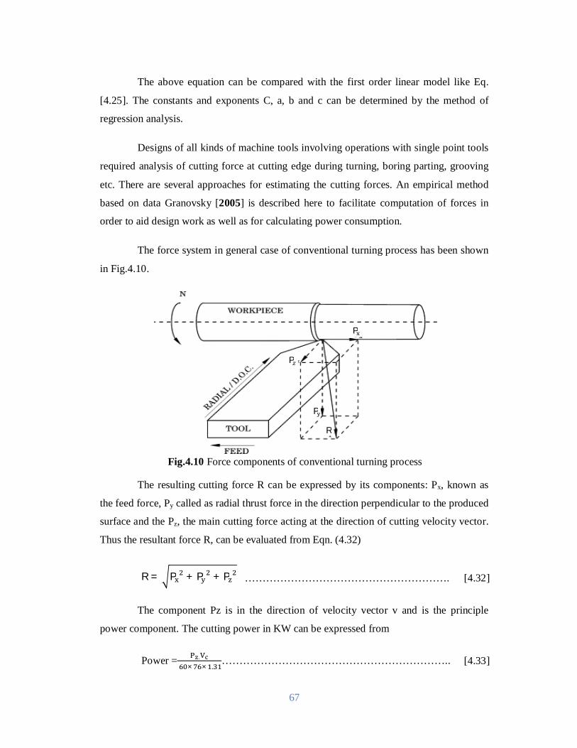
67
The above equation can be compared with the first order linear model like Eq.
[4.25]. The constants and exponents C, a, b and c can be determined by the method of
regression analysis.
Designs of all kinds of machine tools involving operations with single point tools
required analysis of cutting force at cutting edge during turning, boring parting, grooving
etc. There are several approaches for estimating the cutting forces. An empirical method
based on data Granovsky [2005] is described here to facilitate computation of forces in
order to aid design work as well as for calculating power consumption.
The force system in general case of conventional turning process has been shown
in Fig.4.10.
Fig.4.10 Force components of conventional turning process
The resulting cutting force R can be expressed by its components: Px, known as
the feed force, Py called as radial thrust force in the direction perpendicular to the produced
surface and the Pz, the main cutting force acting at the direction of cutting velocity vector.
Thus the resultant force R, can be evaluated from Eqn. (4.32)
R = P + P + P …………………………………………………. [4.32]
The component Pz is in the direction of velocity vector v and is the principle
power component. The cutting power in KW can be expressed from
Power = . × × .
……………………………………………………….. [4.33]
P
P
P
R
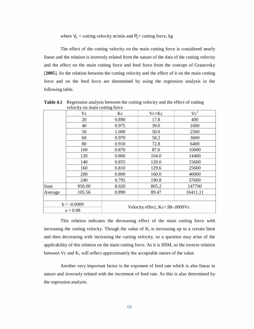
68
where V = cutting velocity m/min and P = cutting force, kg
The effect of the cutting velocity on the main cutting force is considered nearly
linear and the relation is inversely related from the nature of the data of the cutting velocity
and the effect on the main cutting force and feed force from the concept of Granovsky
[2005]. So the relation between the cutting velocity and the effect of it on the main cutting
force and on the feed force are determined by using the regression analysis in the
following table.
Table 4.1 Regression analysis between the cutting velocity and the effect of cutting velocity on main cutting force
Vc Kc Vc×Kc Vc2 20 0.890 17.8 400 40 0.975 39.0 1600 50 1.000 50.0 2500 60 0.970 58.2 3600 80 0.910 72.8 6400
100 0.870 87.0 10000 120 0.860 104.0 14400 140 0.855 120.0 15600 160 0.810 129.6 25600 200 0.800 160.0 40000 240 0.795 190.8 57600
Sum 950.00 8.020 805.2 147700 Average 105.56 0.890 89.47 16411.11
b = -0.0009 Velocity effect, Kc=.98-.0009Vc a = 0.98
This relation indicates the decreasing effect of the main cutting force with
increasing the cutting velocity. Though the value of Kc is increasing up to a certain limit
and then decreasing with increasing the cutting velocity, so a question may arise of the
applicability of this relation on the main cutting force. As it is HSM, so the inverse relation
between Vc and Kc will reflect approximately the acceptable nature of the value
Another very important factor is the exponent of feed rate which is also linear in
nature and inversely related with the increment of feed rate. So this is also determined by
the regression analysis.
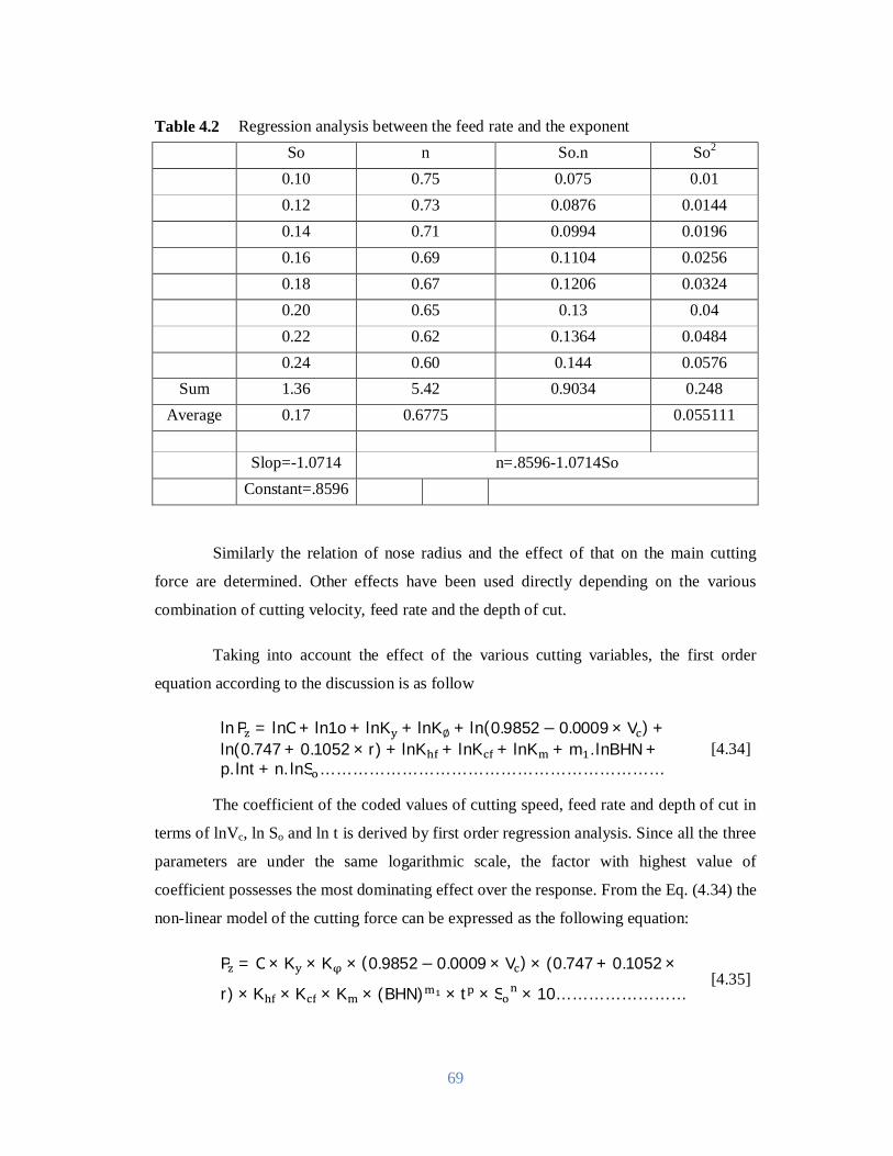
69
Table 4.2 Regression analysis between the feed rate and the exponent So n So.n So2
0.10 0.75 0.075 0.01 0.12 0.73 0.0876 0.0144 0.14 0.71 0.0994 0.0196 0.16 0.69 0.1104 0.0256 0.18 0.67 0.1206 0.0324 0.20 0.65 0.13 0.04 0.22 0.62 0.1364 0.0484 0.24 0.60 0.144 0.0576
Sum 1.36 5.42 0.9034 0.248 Average 0.17 0.6775 0.055111
Slop=-1.0714 n=.8596-1.0714So Constant=.8596
Similarly the relation of nose radius and the effect of that on the main cutting
force are determined. Other effects have been used directly depending on the various
combination of cutting velocity, feed rate and the depth of cut.
Taking into account the effect of the various cutting variables, the first order
equation according to the discussion is as follow
ln P = lnC + ln1o + lnK + lnK∅ + ln(0.9852 − 0.0009 × V ) +ln(0.747 + 0.1052 × r) + lnK + lnK + lnK + m . lnBHN +p. lnt + n. lnS ………………………………………………………
[4.34]
The coefficient of the coded values of cutting speed, feed rate and depth of cut in
terms of lnVc, ln So and ln t is derived by first order regression analysis. Since all the three
parameters are under the same logarithmic scale, the factor with highest value of
coefficient possesses the most dominating effect over the response. From the Eq. (4.34) the
non-linear model of the cutting force can be expressed as the following equation:
P = C × K × K × (0.9852− 0.0009 × V ) × (0.747 + 0.1052 ×
r) × K × K × K × (BHN) × t × S × 10…………………… [4.35]

70
As for the single work-tool combination the values of C, K , K , K , K , K , BHN are
constant. So assuming K = 10 × C × K × K × K × K × K × (BHN)
P = K(0.9852 − 0.0009V )(0.747 + 0.1052 × r)t S …................ [4.36]
Again for single work-tool combination the values of
C, K , K , K , K , K , BHN, K are constant for feed force. Assuming
K = 10 × C × K × K × K × K × K × K × (BHN)
From the regression analysis the relation between So and q is 푛 = 0.8− 0.2푆
The feed force (P ) can be modeled considering the different effects as follows
P = K (0.88 − 0.0014V )t S ………………………………............. [4.37]
4.3 Experimental Model Validation of Cutting Force
In order to validate the model, the cutting force obtained during turning 42
CrMo4 steel at different Vc-So-t combinations has been compared with the predicted value.
Following tables show the combination of Vc-So-t for different test conditions.
where
K = Coefficient, the effect of rake angle for x, z direction
K = Coefficient, the effect of principle cutting edge for x, z direction
K = Coefficient, the effect of tool wear for x, z direction
K = Coefficient, the effect of cutting fluid used for x, z direction
K = Material transfer coefficient for x, z direction
BHN = Brinnel Hardness Number for workpiece material
m1 = Exponent of BHN
t = Depth of cut, mm
P = Exponent of t
So = Feed rate, mm/rev
n = Exponent of So
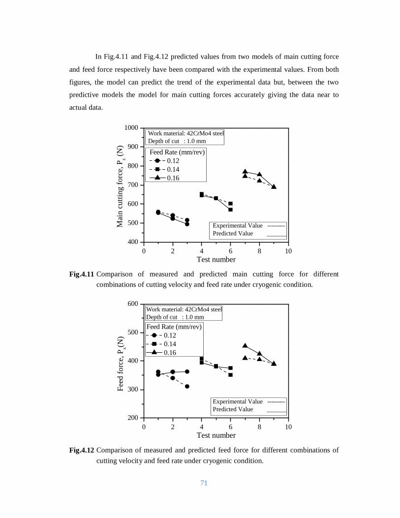
71
In Fig.4.11 and Fig.4.12 predicted values from two models of main cutting force
and feed force respectively have been compared with the experimental values. From both
figures, the model can predict the trend of the experimental data but, between the two
predictive models the model for main cutting forces accurately giving the data near to
actual data.
0 2 4 6 8 10400
500
600
700
800
900
1000
Mai
n cu
tting
forc
e, P
z (N)
Test number
Work material: 42CrMo4 steelDepth of cut : 1.0 mm
Experimental Value ---------Predicted Value
Feed Rate (mm/rev) 0.12 0.14 0.16
Fig.4.11 Comparison of measured and predicted main cutting force for different
combinations of cutting velocity and feed rate under cryogenic condition.
0 2 4 6 8 10200
300
400
500
600
Feed
forc
e, P
x(N)
Test number
Work material: 42CrMo4 steelDepth of cut : 1.0 mm
Experimental Value ---------Predicted Value
Feed Rate (mm/rev) 0.12 0.14 0.16
Fig.4.12 Comparison of measured and predicted feed force for different combinations of
cutting velocity and feed rate under cryogenic condition.

72
5.1 Cutting Temperature
From the data calculated from the model, with the increase in Vc, So and t
generally cutting zone temperature increases due to increased energy input and it could be
expected that cryogenic condition would be more effective at higher values of Vc, So and t.
The average chip-tool interface temperature (θi) has been plotted against cutting speed for
different work-tool combinations, feed rates and environments undertaken. Fig.2.5 is
showing how and to what extent θi has decreased due to cryogenic condition application
under the different experimental conditions. With the increase in Vc, So and t, θi increased
as usual, even under cryogenic cooling condition cutting temperature shows the similar
trend. Under cryogenic cooling condition cutting temperature reduced for all the cases but
in different degree.
Under low speed-feed condition and apparently the temperature is decreased
drastically and a small reduction is observed under high speed-feed condition. Even such
apparently small reduction in the cutting temperature is expected to have some favorable
influence on other machinability indices. With the increase in cutting velocity, plastic
contact is increased and made the jet less effective to enter into the interface. Due to this,
temperature reduction rate is lower under high speed-feed condition.
The effect of cryogenic cooling condition on machining performance is always
dominant over machining under dry condition due to internal mechanics of liquid nitrogen
flow jet. As liquid nitrogen jet is pressurized enough to gain huge velocity, it is able to
penetrate in the chip-tool interface zone thus reducing chip-tool contact length resulting
lower values of frictional co-efficient due to less sliding contact. It can be stated
undoubtedly that cutting temperature is greatly influenced by the changes of cutting
Chapter-5
Discussion on Results
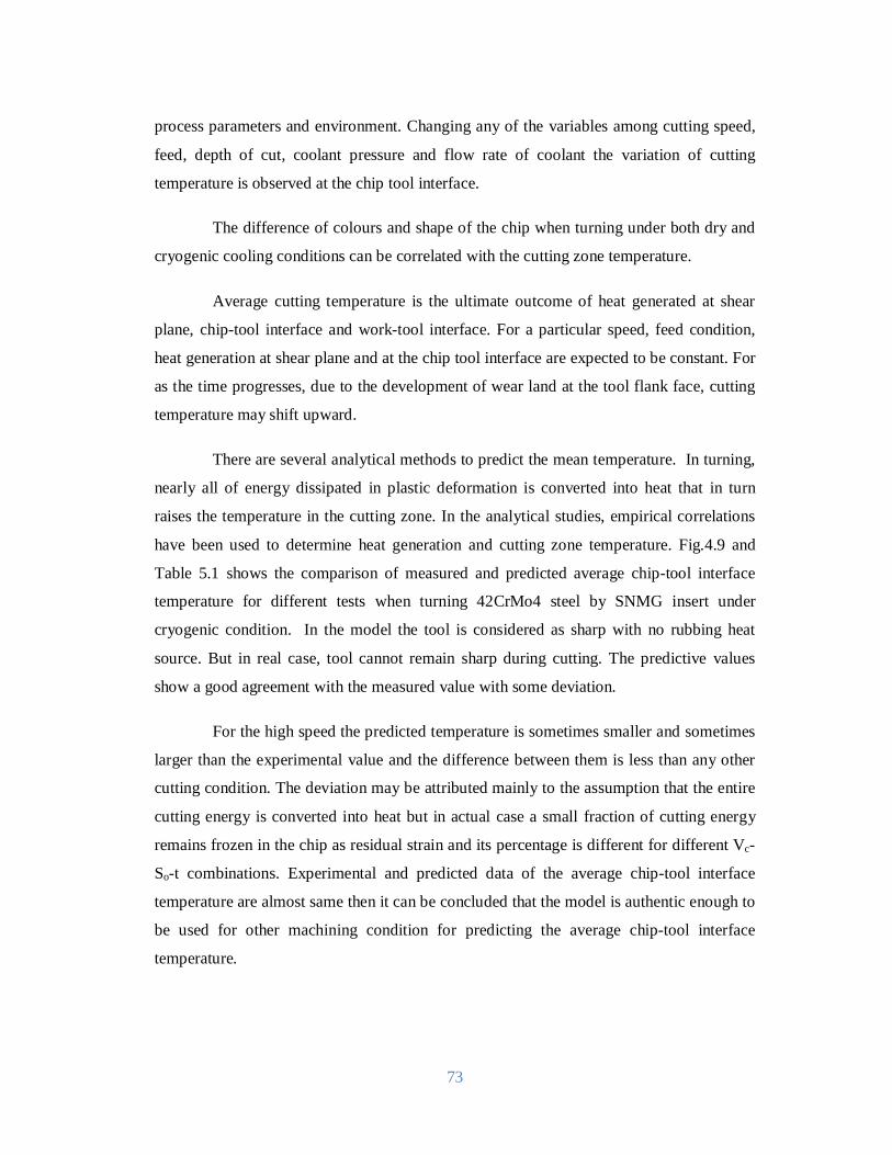
73
process parameters and environment. Changing any of the variables among cutting speed,
feed, depth of cut, coolant pressure and flow rate of coolant the variation of cutting
temperature is observed at the chip tool interface.
The difference of colours and shape of the chip when turning under both dry and
cryogenic cooling conditions can be correlated with the cutting zone temperature.
Average cutting temperature is the ultimate outcome of heat generated at shear
plane, chip-tool interface and work-tool interface. For a particular speed, feed condition,
heat generation at shear plane and at the chip tool interface are expected to be constant. For
as the time progresses, due to the development of wear land at the tool flank face, cutting
temperature may shift upward.
There are several analytical methods to predict the mean temperature. In turning,
nearly all of energy dissipated in plastic deformation is converted into heat that in turn
raises the temperature in the cutting zone. In the analytical studies, empirical correlations
have been used to determine heat generation and cutting zone temperature. Fig.4.9 and
Table 5.1 shows the comparison of measured and predicted average chip-tool interface
temperature for different tests when turning 42CrMo4 steel by SNMG insert under
cryogenic condition. In the model the tool is considered as sharp with no rubbing heat
source. But in real case, tool cannot remain sharp during cutting. The predictive values
show a good agreement with the measured value with some deviation.
For the high speed the predicted temperature is sometimes smaller and sometimes
larger than the experimental value and the difference between them is less than any other
cutting condition. The deviation may be attributed mainly to the assumption that the entire
cutting energy is converted into heat but in actual case a small fraction of cutting energy
remains frozen in the chip as residual strain and its percentage is different for different Vc-
So-t combinations. Experimental and predicted data of the average chip-tool interface
temperature are almost same then it can be concluded that the model is authentic enough to
be used for other machining condition for predicting the average chip-tool interface
temperature.
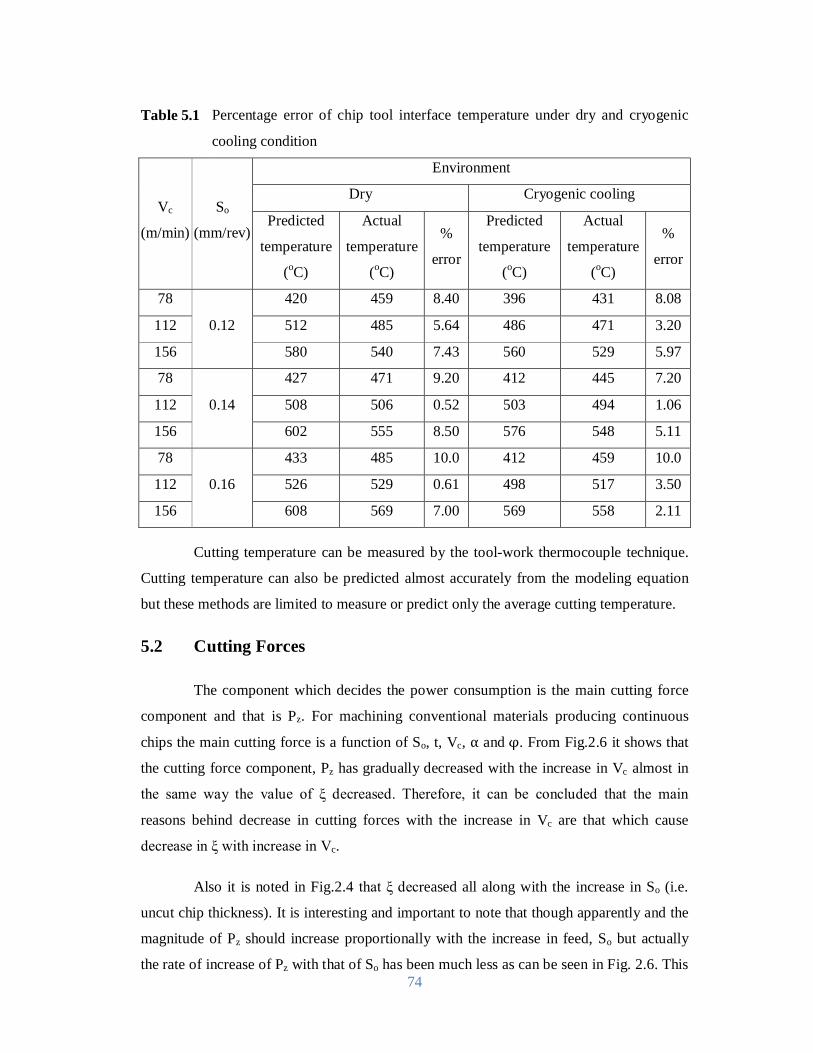
74
Table 5.1 Percentage error of chip tool interface temperature under dry and cryogenic
cooling condition
Vc
(m/min)
So
(mm/rev)
Environment
Dry Cryogenic cooling
Predicted
temperature
(oC)
Actual
temperature
(oC)
%
error
Predicted
temperature
(oC)
Actual
temperature
(oC)
%
error
78
0.12
420 459 8.40 396 431 8.08
112 512 485 5.64 486 471 3.20
156 580 540 7.43 560 529 5.97
78
0.14
427 471 9.20 412 445 7.20
112 508 506 0.52 503 494 1.06
156 602 555 8.50 576 548 5.11
78
0.16
433 485 10.0 412 459 10.0
112 526 529 0.61 498 517 3.50
156 608 569 7.00 569 558 2.11
Cutting temperature can be measured by the tool-work thermocouple technique.
Cutting temperature can also be predicted almost accurately from the modeling equation
but these methods are limited to measure or predict only the average cutting temperature.
5.2 Cutting Forces
The component which decides the power consumption is the main cutting force
component and that is Pz. For machining conventional materials producing continuous
chips the main cutting force is a function of So, t, Vc, α andφ. From Fig.2.6 it shows that
the cutting force component, Pz has gradually decreased with the increase in Vc almost in
the same way the value of ξ decreased. Therefore, it can be concluded that the main
reasons behind decrease in cutting forces with the increase in Vc are that which cause
decrease in ξ with increase in Vc.
Also it is noted in Fig.2.4 that ξ decreased all along with the increase in So (i.e.
uncut chip thickness). It is interesting and important to note that though apparently and the
magnitude of Pz should increase proportionally with the increase in feed, So but actually
the rate of increase of Pz with that of So has been much less as can be seen in Fig. 2.6. This
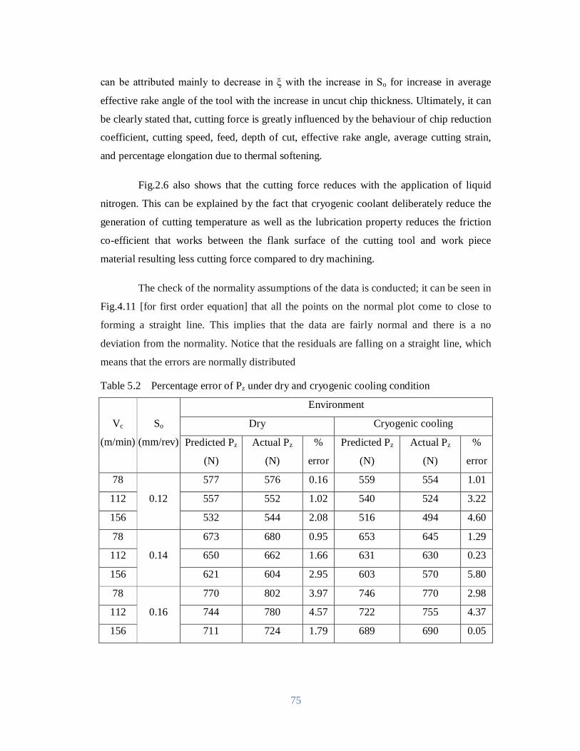
75
can be attributed mainly to decrease in ξ with the increase in So for increase in average
effective rake angle of the tool with the increase in uncut chip thickness. Ultimately, it can
be clearly stated that, cutting force is greatly influenced by the behaviour of chip reduction
coefficient, cutting speed, feed, depth of cut, effective rake angle, average cutting strain,
and percentage elongation due to thermal softening.
Fig.2.6 also shows that the cutting force reduces with the application of liquid
nitrogen. This can be explained by the fact that cryogenic coolant deliberately reduce the
generation of cutting temperature as well as the lubrication property reduces the friction
co-efficient that works between the flank surface of the cutting tool and work piece
material resulting less cutting force compared to dry machining.
The check of the normality assumptions of the data is conducted; it can be seen in
Fig.4.11 [for first order equation] that all the points on the normal plot come to close to
forming a straight line. This implies that the data are fairly normal and there is a no
deviation from the normality. Notice that the residuals are falling on a straight line, which
means that the errors are normally distributed
Table 5.2 Percentage error of Pz under dry and cryogenic cooling condition
Vc
(m/min)
So
(mm/rev)
Environment
Dry Cryogenic cooling
Predicted Pz
(N)
Actual Pz
(N)
%
error
Predicted Pz
(N)
Actual Pz
(N)
%
error
78
0.12
577 576 0.16 559 554 1.01
112 557 552 1.02 540 524 3.22
156 532 544 2.08 516 494 4.60
78
0.14
673 680 0.95 653 645 1.29
112 650 662 1.66 631 630 0.23
156 621 604 2.95 603 570 5.80
78
0.16
770 802 3.97 746 770 2.98
112 744 780 4.57 722 755 4.37
156 711 724 1.79 689 690 0.05
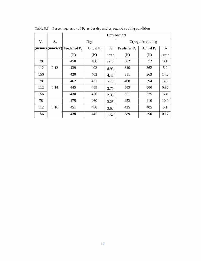
76
Table 5.3 Percentage error of Px under dry and cryogenic cooling condition
Vc
(m/min)
So
(mm/rev)
Environment
Dry Cryogenic cooling
Predicted Px
(N)
Actual Px
(N)
%
error
Predicted Px
(N)
Actual Px
(N)
%
error
78
0.12
450 400 12.50 362 352 3.1
112 439 403 8.93 340 362 5.9
156 420 402 4.48 311 363 14.0
78
0.14
462 431 7.19 408 394 3.8
112 445 433 2.77 383 380 0.98
156 430 420 2.38 351 375 6.4
78
0.16
475 460 3.26 453 410 10.0
112 451 468 3.63 425 405 5.1
156 438 445 1.57 389 390 0.17

77
Chapter-6
Conclusions 6.1 Conclusions
The aim of the present research work is to develop analytical models of cutting
temperature and cutting force while turning 42CrMo4 steel by uncoated carbide insert
(SNMG 120408-26TTS) under cryogenic condition. Modeling of the cutting temperature
has been done by analytical approach. On the other hand, main cutting force has been
studied and analyzed to correlate with cutting process variables such as cutting speed, feed
rate and depth of cut. Experimental value of chip reduction coefficient, cutting temperature
and cutting force are taken for validity test of cutting temperature and cutting force as well
as for deriving some input variables for the predictive model. Based on the research work
the following conclusions can be drawn:
i) At the first step, chip shape and colour for 42CrMo4 steel is studied. When
machined under cryogenic cooling condition the color and shape of the chip
indicates the amount of reduction of temperature due cryogenic condition
enabled favourable chip-tool interaction and elimination of even trace of
built-up edge formation.
ii) In the second step, chip reduction co-efficient ξ has a proportional relation
with the cutting force theoretically. So, the lower value of chip reduction
co-efficient is better. Controlling coolant pressure and flow rate of liquid
nitrogen jet, effective lubrication can be carried out resulting more reduced
friction at the interface zone and thus lower values of ξ can be obtained as
desired. The model shows that with decreasing the value of ξ the cutting
temperature will decrease.
iii) Cutting temperature is found to be proportional with cutting speed, feed rate
and depth of cut. Application of liquid nitrogen reduces this high cutting
78
temperature when compared to dry cutting. The reduction is between 1.5
and 6.5 % for the average chip-tool interface temperature for different Vc-
So-t combinations. For as the time progresses, due to the development of
wear land at the tool flank face, cutting temperature may shift upward,
while speed, feed, depth of cut, pressure and flow rate of liquid nitrogen jet
are constant. But this transient character is found to be not significant to a
considerable extent. Approximately 7% variation has been observed in
cutting temperature values from the analytical model.
iv) The trends of cutting forces can be increasing or decreasing with the
increase of cutting process parameters. This behaviour solely depends on
the range of cutting process variables that are considered as experimental
condition of a particular research. From the modelled equation, main cutting
force and feed force found to decrease with the increase of speed, and
cutting forces increases with the increase of feed and depth of cut. With the
application of liquid nitrogen, the reductions of forces have a significant
amount.
v) From the analytical model in cryogenic cooling condition, the cutting
temperature can be predicted accurately within error level of 10%.
vi) From the first order model, main cutting force can be predicted with
maximum error of 5% and feed force can be predicted with maximum error
of 14% in the cryogenic cooling condition.
6.2 Scope for Future Work
i) Three variables such cutting velocity, feed rate and the depth of cut are
considered for the experimental part, for getting the response parameter.
This research work can be extended by increasing the variable. The new
variable may be the cryogenic condition parameter such as pressure and
flow rate of the jet.
ii) In this research, analytical modelling of cutting temperature has been
developed for a particular tool work combination. Another modification of
the analytical model can be the model with wear out tool. In that method a

79
rubbing heat source (tertiary) need to be considered at the surface of the
zone, where the clearance face of the tool rubs the newly machined surface
deformation can occur.
iii) The parameter of the liquid nitrogen jet such flow rate of LN2 and the outlet
pressure of the jet have significant effect on cutting temperature and cutting
force. In the present work these factors are not studied. So, these factors can
be studied experimentally in future by doing the experiment with different
pressure and flow rate of LN2. Then the predictive equation for the cutting
force and temperature can be derived with the cutting variables and the
cryogenic variables.
80
ReferencesAhmed, M.I., A.F. Ismail, Y.A. Abakr and A.K.M.N. Amin, “Effectiveness of cryogenic
machining with modified tool holder”. Journal of Materials Processing
Technology,Vol. 185(1-3): 91-96, 2007.
Al-Ahmari, A.M.A., “Predictive Machinability Models for a Selected Hard Material in
Turning Operations”, J. of Mat. Pro. Tech., Vol. 190(1-3), pp.305-311, 2007.
Aronson, R.B., 1995, “Why Dry Machining?” J. Manuf. Sci. & Eng., Vol. 122 pp. 33–36.
Attia M.H. and Kops L., “A New Approach to Cutting Temperature Prediction
Considering the Thermal Constriction Phenomenon in Multi-Layer Coated Tool”,
Annals of CIRP, Vol. 53(1), pp. 47-52, 2004.
Bailey, J.A. and Bhavandia, D.G., “Correlation of Flow Stress with Strain Rate and
Temperature during Machining”, Trans. of ASME, pp. 94-98. 1973.
Bagci, A., “Prediction of Shear Plane in Machining From Work Material Strain-Hardening
Characteristics”, Trans. of ASME, Vol. 105(2), pp.129-131, 1973.
Bareggi, A., O’Donnell, G.E. and Torrance, A., “Modelling Thermal Effects in Machining
by Finite Element Methods”, Proc. of the 24th International Manufacturing
Conference, Vol.1, pp.263-272, 2007.
Barrow, G., “A Review of Experimental and Theoretical Techniques for Assessing Cutting
Temperatures”, Annals of CIRP, Vol. 22(2), pp. 203–211, 1973,
Beaubien S.J. and Cattaneo A.G., “A Study of the Role of Cutting Fluid in Machining
Operating”, Lubrication Engineering, Vol.10, pp. 74-79, 1964.
81
Boothroyd, G., “Temperatures in Orthogonal Metal Cutting”, Proceedings of the
Institution of Mechanical Engineers, Vol. 177 (29), pp. 789–803, 1963.
Bouzid, W., Zghal, A.and Ben Ayed, K., “Carbide and Ceramic Tool Life in High Speed
Turning”, Int. Journal of Vehicle Design, Vol.39 (1-2), pp.140-153, 2004.
Brockhoff, T.,Walter, A., “Fluid Minimization in Cutting and Grinding”. Abrasives
Magazine pp. 38-42, 1998.
Byrne, G. and Scholta, E. “Environmentally Clean Machining Processes- A Strategic
Approach." Annals of CIRP, 42(1): 471-474, 1993.
Campbell, J.D., “Dynamic Plasticity: Macroscopic and Microscopic Aspects”, Material
Science and Engineering, Vol. 27(2), pp. 3-21, 1973.
Carvalho, S.R., Lima, E., Silva, S.M.M., Machado, A.R., and Guimaraes, G.,
“Temperature Determination at the Chip-Tool Interface using an Inverse Thermal
Model Considering the Tool and Tool Holder”, Journal of Materials Processing
Technology, Vol. 179(1-3), pp. 97-104, 2006.
Chattopadhyay, A. K. and Chattopadhyay, A. B., “Wear and Performance of Coated
Carbides and Ceramic Tools Wear”, Journal of Brazilian Society, Vol.80, pp.239-
253, 1982.
Chao, B.T. and Trigger, K.J. “The Significance of the Thermal Number in Metal
Cutting”, Transactions of the ASME, Vol. 75, pp.109–120, 1953.
Chao, B.T. and Trigger, K.J. “Temperature Distribution at the Tool-chip Interface in Metal
Cutting”, Trans. of the ASME, Vol. 77(2), pp.1107–1121, 1955.
Chao, B.T. and Trigger, K.J. “Temperature Distribution at Tool-chip and Tool-work
Interfacein Metal Cutting”. Trans. of ASME, Vol. 80(1), pp.311–320, 1958.
Dawson, P.R. and Malkin, S., “Inclined Moving Heat Source Model for Calculating Metal
Cutting Temperatures”, Trans. of ASME, Vol. 106(3), pp. 179–186. 1984.
82
Dhar, N.R., S. Paul and Chattopadhyay, A.B., “Machining of AISI 4140 Steel under
Cryogenic Cooling-Tool Wear, Surface Roughness and Dimensional Deviation,”
J. of Mat. Pro. Tech., Vol. 123, pp. 483-489, 2002.
Dhar, N.R., Paul, S., Chattopadhyay, A.B., “Role of Cryogenic Cooling on Cutting
Temperature in Turning Steel”, Journal of Manufacturing Science and
Engineering, vol. 124(1), pp. 146-154, 2002.
Dhar, N.R., and Kamruzzaman, M., “Cutting Temperature, Tool Wear, Surface Roughness
and Dimensional Deviation in Turning AISI-4037 Steel Under Cryogenic
Condition”, Int. J. of Machine Tools and Manuf., Vol. 47, pp. 754-759, 2007.
Elanayar, S.V.T. and Shin, Y.C., “Modeling of Tool Forces for Worn Tools: Flank Wear
Effects”, Trans. of ASME, Journal of Manufacturing Science and Engineering,
Vol. 118 (3), pp. 359–366, 1996.
Endrino, J.L., Fox-Rabinovich G.S. and Gey C., “Hard AlTiN, AlCrNpvd Coatings for
Machining of Austenitic Stainless Steel”, Surface and Coatings Technology,
Vol.200(24), pp.6840-6845, 2006.
Ezugwu, E.O. and Tang, S.H., “Surface Abuse when Machining Cast Iron (G-17) and
Nickel-Base Super Alloy (Inconel 718) with Ceramic Tools”, J. of Mat. Pro.
Tech., Vol. 55, pp. 63–69, 1995.
Gonzalo O., Jauregi H., Uriarte L.G. and López de Lacalle, L.N., “Prediction of Specific
Force Coefficients from a FEM Cutting Model”, The International Journal of
Advanced Manufacturing Technology, Vol. 43(3/4) , pp. 348-356, 2009.
Grzesik W. and Nieslony, P., “Physics Based Modelling of Interface Temperatures in
Machining with Multilayer Coated Tools at Moderate Cutting Speeds”, Int.
Journal of Machine Tools and Manufacture, Vol. 44(9) , pp. 889-901, 2004.
Grzesik, W., Bartoszuk, M. and Niesłony, P., “Finite Element Modelling of Temperature
Distribution in the Cutting Zone in Turning Processes with Differently Coated
Tools”, Proc. of 13th International Scientific Conference on Achievement in
Mechanical and Materials Engineering, pp. 259-262, 2005.

83
Grzesik, W. and Bartoszuk, M., “Prediction of Temperature Distribution in the Cutting
Zone using Finite Difference Approach”, International Journal of Machining and
Machinability of Materials, Vol. 6 (1/2), pp .43-53, 2009.
Hahn, R.S. “On the Temperature Developed at the Shear Plane in the Metal Cutting
Process”. Proc. of First U.S. National Congress of App. Mech, pp 661-666, 1951.
Hong, S.Y., “New Cooling Approach and Tool Life Improvement in Cryogenic Machining
of Titanium Alloy Ti-6Al-4V”, International Journal of Machine Tools &
Manufacture, Vol. 41, pp. 2245-2260, 2001.
Henry Northcott ,“A Treaties on Lathe Turning”, Simple, Mechanical and Ornamental,
1868.
Huang, Y. and Liang, S.Y., “Cutting Forces Modeling Considering the Effect of Tool
Thermal Property-Application to CBN Hard Turning”, International Journal of
Machine Tools & Manufacture, Vol. 43(3), pp. 307–315, 2003.
Huang, Y. and Liang, S.Y., “Modeling of CBN Tool Flank Wear Progression in Finish
Hard Turning”, ASME Journal of Manufacturing Science and Engineering, Vol.
126 (1), pp. 98–106, 2004.
Ibraheem, A.F., Shather, S.K. and Khalaf, K.A., “Prediction of Cutting Forces by using
Machine Parameters in End Milling Process”, Eng. &Tech., Vol.26 (11), 2008.
Jen, T.C. and Lavine, A.S., “Prediction of Tool Temperatures in Cutting”, Proceedings of
the Seventh International Symposium on Transport Phenomena in Manufacturing,
pp. 211–216, 1994.
Jian, L. and Hongxing, L., “Modeling System Error in Batch Machining Based on Genetic
Algorithms”, Int. J. of Machine Tools & manuf., Vol. 43(6), pp. 599-604, 2003.
Jiao, Y., Lei, S., Pei Z.J. and Lee, E.S., “Fuzzy Adaptive Networks in Machining Process
Modeling: Surface Roughness Prediction for Turning Operations”, International
Journal of Machine Tools & Manufacture, Vol. 44, pp. 1643-1651, 2004.
Kato, T. and Fujii, H., “PVD Film Method for Measuring the Temperature Distribution in
Cutting Tools”, Trans. ASME, J. Eng. for Industry, Vol. 118, pp. 117–122, 1996.
84
Khan A.A. and Ahmed M. I., “Improving Tool Life using Cryogenic Cooling”, J. of Mat.
Pro. Tech., Vol. 196, pp. 149-154, 2008.
Khidhir, B.A., Mohamed B. and Younis, M.A.A., “Modification Approach of Fuzzy Logic
Model for Predicting of Cutting Force When Machining Nickel Based Hastelloy
C-276”American J. of Eng. and Applied Sci., Vol. 3 (1), pp.207-213, 2010.
Kim, K.W., Lee, W.Y. and Sin, H., “A Finite Element Analysis for the Characteristics of
Temperature and Stress in Micro-Machining Considering the Size Effect”, Int.
Journal of Machine Tools & Manufacture, Vol. 39 (9), pp.1507–1524, 1999.
Kienzle, O. and Victor, H., “Spezifische Shnittkraefte Bei Der Metall-Bearbeitung”,
Werkstattstehnik und Maschinenbau, Bd. 47, H.5, 1957.
Kitagawa, T., Kubo, A. and Maekawa, K., “Temperature and Wear of Cutting Tools in
High Speed Machining of Inconel 718 and Ti-6V-2Sn”, Wear, Vol. 202, pp.142,
1997.
Klocke, F., Konig, W. and Gerschwiler, K., “Advanced Machining of Titanium and
Nickel-Based Alloys”, Proceedings of the fourth international conference on
Advanced Manufacturing Systems and Technology, pp. 7-21, 1996.
Komanduri, R. and Hou, Z.B., “Thermal Modeling of the Metal Cutting Process, Part 1:
Temperature Rise Distribution due to Shear Plane Heat Source”, Int. J. Mech.
Sci., Vol. 42, pp. 1715–1752, 2000.
Komanduri, R. and Hou, Z.B., “Thermal Modeling of the Metal Cutting Process, Part 2:
Temperature Rise Distribution due to Frictional Heat Source at the Tool–Chip
Interface”, Int. J. Mech. Sci., Vol. 43, pp. 57–88, 2001.
Kumar, K.V.B.S.K. and S.K. Choudhury, “Investigation of tool wear and cutting force in
cryogenic machining using design of experiments”. Journal of Materials
Processing Technology, Vol. 203(1-3): pp. 95-101, 2008.
Kumar, A.S., Rahman, M. and Ng, S.L., “Effect of High-Pressure Coolant on Machining
Performance”, The International Journal of Advanced Manufacturing
Technology, Vol. 20(2), pp. 83-91, 2002.
85
Lazoglu ,I. and Altintas, Y., “Prediction of Tool and Chip Temperature in Continuous and
Interrupted Machining”, International Journal of Machine Tools & Manufacture,
Vol. 42, pp. 1011–1022, 2002.
Lee, E.H. and Shaffer, B.H., “The Theory of Plasticity Applied to a Problem of
Machining”, Journal of applied mechanics, Vol. 18, pp. 405–413, 1951.
Leonardo, R.S. and Davim, J.P., “The Effect of Tool Geometry on the Machinability of
Polyamide During Precision Turning”, Journal of Composite Materials, Vol.
43(23), pp. 2793-2803, 2009.
List, G., Nouari, M., G´ehin, D., Gomez, S., Manaud, J.P., Le Petitcorps, Y. and Girot, F.,
“Wear Behavior of Cemented Carbide Tools in Dry Machining of Aluminum
Alloy”, Wear, Vol. 259, pp. 1177–1189, 2005.
Liu, X.L., Wen, D.H., Li, Z.J., Xiao, L. and Yan, F.G., “Experimental Study on Hard
Turning Hardened GCr15 Steel with PCBN Tool”, Journal of Materials
Processing Technology, Vol. 129, pp.217-221, 2002.
Loewen, E.G. and Shaw, M.C., “On the Analysis of Cutting Tool Temperatures”, Trans. of
ASME, Vol. 76, pp. 217–231, 1954.
Luo, T., Lu, W., Krishnamurthy, K. and McMillin, B., “A Neural Network Approach for
Force and Contour Error Control in Multi-Dimensional End Milling Operations”,
Int. J. Machine Tools and Manufacture, Vol. 38, pp. 1343-1359. 1998.
Mamalis, A.G., Kundrák, J., Markopoulos, A. and Manolakos, D.E., “On the Finite
Element Modelling of High Speed Hard Turning”, Int. J. Adv. Manuf. Tech., Vol.
38, pp. 441–446, 2008.
Marusich, T.D. and Ortiz, M., “Modeling and Simulation of High-Speed Machining”, Int.
J. Num. Meth.Eng., Vol. 38, pp. 3675-3694, 1995.
Marusich, T.D., “Effects of Friction and Cutting Speed on Cutting Force”, Proceedings of
ASME Congress, New York, pp. 197–204, 2001.
Mazurkiewicz, M., Kubula, Z. and Chow, J., “Metal Machining with High Pressure Water
Jet Cooling Assistance-A New Possibility”, J. Eng. Ind., Vol.111, pp. 7-12, 1989.
86
Merchant, M.E., “Mechanics of the Metal Cutting Process, Part 2: Plasticity Conditions in
Orthogonal Cutting”, J. Appl. Phys, Vol. 16, pp. 318–324, 1945.
Merchant, M.E., “Mechanics of the Metal Cutting Process”, Journal of applied physics,
Vol. 16(5), pp. 267-275, 1945.
McFeron, D.E., and Chao, B.T., “Transient Interface Temperatures in Plain Peripheral
Milling”, Trans. of ASME, J. of Eng. for Industry, Vol. 80, pp. 321–329, 1958.
Montgomery, Douglas C, “Design and Analysis of Experiments: Response Surface
Method and Designs”, New Jersey: John Wiley and Sons, Inc., 2005.
Muller, C. and Blumke, R., “Influence of Heat Treatment and Cutting Speed on Chip
Segmentation of Age Hardenable Aluminum Alloy”, Material Science and
Technology, Vol.17, pp. 651-654, 2001.
Narutaki, N. and Yamane, Y., “Tool Wear and Cutting Temperatures of CBN Tools in
Machining Hardened Steels”, Annals of CIRP, Vol. 28(1), pp.23-27, 1979.
Nigm, M.M., Sadek, M.M., and Tobias, S.A., “Dimensional Analysis of the Steady State
Orthogonal Cutting Process”, IJMTDR, Vol. l7(l), pp.l-18, 1977.
Obikawa, T. and Usui, E., “Computational Machining of Titanium Alloy-Finite Element
Modeling and a Few Results”, Journal of Manufacturing Science and
Engineering, Vol. 118(2), pp. 208-215, 1996.
Obikawa, T., Sasahara, H., Shirakashi, T. and Usui, E., “Application of Computational
Machining Method to Discontinuous Chip Formation”, Journal of Manufacturing
Science and Engineering, Vol. 119(4), pp. 667-674, 1997.
Oxley, P.L.B., “Mechanics of Machining, an Analytical Approach to Assessing
Machinability”, Ellis Horwood, Chichester,pp. 223-227, 1989.
Oxley, P.L.B., “Mechanics of Machining: An Analytical Approach to Assessing
Machinability”, John Wiley & Sons, New York, USA, 1989.
87
Özel, T. and Altan, T., “Process Simulation using Finite Element Method— Prediction of
Cutting Forces, Tool Stresses and Temperatures in High Speed Flat End Milling”,
Int. J. of Machine Tools & Manufacture, Vol. 40, pp. 713–738, 2000.
Özel, T., Lucchi, M., Rodríguez, C.A. and Altan, T., “Prediction of Chip Formation and
Cutting Forces in Flat End Milling: Comparison of Process Simulations with
Experiments”, Transactions of NAMRI/SME, Vol. XXVI, pp. 231-237, 1998.
Radulescu, R. and Kapoor, S.G., “An Analytical Model for Prediction of Tool
Temperature Fields during Continuous and Interrupted Cutting”, Trans. of
ASME, Journal of Engineering for Industry, Vol. 116, pp. 135–140, 1994.
Rahman, M., Seah, W.K.H. and Teo, T.T., “The Machinability of Inconel 718”, Journal of
Materials Processing Technology, Vol. 63(1-3), pp.199–204, 1997.
Reed, R.P. and Clark, A.F., “Materials at Low Temperatures”, American Society for
Metals, Carnes Publication, Metal Park, OH, 1983.
Ren, H. and Altintas, Y., “Mechanics of Machining with Chamfered Tools”, Trans. of
ASME, J. of Manuf. and Eng. and Sci., Vol. 122, pp. 650–659, 2000.
Rosenberg, A.M., Rosenberg, O.A., “Calculation of Cutting Forces in Cutting Ductile
Metals”, Sverkhtcerdyne materially, Vol. 14, pp.48-54, 1987.
Paul, S., Dhar, N.R., and Chattopadhyay, A.B, “Beneficial Effects of Cryogenic Cooling
over Dry and Wet Machining on Tool Wear and Surface Finish in Turning AISI
1060 Steel”, J. of Materials Processing Technology, Vol. 116, pp. 44-48, 2001.
Pictet and Cailletet, “The Role of Cryogenics in Machining Processes”, Wear, Vol. 202,
pp.142, 1887.
Piispanen “deck of card” for chip formation by a single shear plane, published in English
forn 1948.
Peter C. Raynor, Steven Cooper and David Leith, “Evaporation of Poly Disperse Multi
Component Oil Droplets”, American Industrial Hygiene Association, “Improving
of the lubricating performance of cutting fluid by Sulfur(S), Phosphorus(P),
Chlorine (Cl) or other pressure additives”, 1996.

88
Popke, H., Emmer, Th. And Steffenhagen, J., 1999, “Environmentally Clean Metal Cutting
Process-Machining on The Way to Dry Machining”, Proceedings of the
Institution of Mechanical Engineers, Part B: J. of Eng. Manuf., pp. 329-332.
Satoshi, I., Teiji, Y., Shinichi, M. and Kazuo, M., “Machinability of Ni3Al Based Inter
Metallic Compounds”, J. of Mat. Pro. Tech., Vol.63 (1-3), pp.181-186, 1997.
Sekhon, G.S. and Chenot, J.L., “Numerical Simulation of Continuous Chip Formation
during Non- Steady Orthogonal Cutting”, Eng. Com., Vol. 10(1), pp. 31-48, 1993.
Shaw, M.C., Cook, N.H. and Smith, P.A., “The Mechanics of Three Dimensional Cutting
Operations”, Trans. of ASME, Vol. 74(3), pp. 1055-1064, 1952.
Shaw, M., “Metal Cutting Principles”, Oxford University Press, United Kingdom, 1989.
Shane Y. Hong and Yucheng Ding, “Cooling Approaches and Cutting Temperatures in
Cryogenic Machining of Ti-6Al- 4V,” International Journal of Machine Tools
and Manufacture, Vol. 41, pp. 1417-1437, 2001.
Shane Y., Hong, Ding and Woo, “Friction and cutting Forces in Cryogenic Machining of
Ti- 6Al-4V,” International Journal of Machine Tools and Manufacture, Vol. 41,
pp. 2271- 2285, 2001.
Sharma, V.S., Dhiman, S., Sehgal, R. and Sharma, S.K., “Estimation of Cutting Forces and
Surface Roughness for Hard Turning using Neural Networks”, Journal of
Intelligent Manufacturing, Vol. 19, pp. 473–483, 2008.
Shatla, M., Yen, Y. C., Castellanos, O., Menegardo, L. and Altan, T., “Prediction of
Cutting Forces, Temperatures and Stresses from Flow Stress Data and Cutting
Conditions”, Proceedings of the Second CIRP International Workshop on
Modeling of Machining Operations, Ecole Centrale De Nantes, Nantes, France,
January 25-26, 1999.
Singh, S.B., Chakraborty, A.K. and Chattopadhyay, A.B., “A Study of the Effects of
Inclusion Contact on the Machinability and Wear Characteristics of 0.24%
Carbon Steel”, J. of Mat. Pro. Tech., Vol.66, pp.90-96, 1997.
89
Smith, A.J.R. and Armarego, J.A., “Temperature Prediction in Orthogonal Cutting with a
Finite Difference Approach”, Annals of CIRP, ., Vol.30, pp.9-13 1981.
Smithey, D.W., Kapoor, S.G. and DeVor, R.E., “A Worn Tool Cutting Force Model for
Three-Dimensional Cutting Operations”, International Journal of Machine Tools
and Manufacture, Vol. 40, pp. 1929–1950, 2000.
Smithey, D.W., Kapoor, S.G. and DeVor, R.E., “A New Mechanistic Model for Predicting
Worn Tool Cutting Forces”, Machining Science and Technology, Vol. 5(1), pp.
23–42, 2001.
Sokovic, M. & Mijanovic, K., “Ecological Aspects of Cutting Fluids and its Influence on
Quantifiable Parameters on Cutting Process”-Journal of Materials Processing
Technology 109 (1-2): 181-189, 2001.
Soo, S.L. and Aspinwall, D.K., “Developments in Modeling of Metal Cutting Processes”,
Journal of Materials: Design and Applications, Vol. 221(4), pp.197-211, 2007.
Sreejith, P.S. and Ngoi, B.K.A., “Dry Machining: Machining of the Future”, Journal of
Materials Processing Technology, Vol. 101, pp. 287-291, 2000.
Strenkowski, J.S. and Athavale, S.M., “A Partially Constrained Eulerian Orthogonal
Cutting Model for Chip Control Tools”, Journal of Manufacturing Science and
Engineering, Vol. 119(4), pp. 681-688, 1997.
Stephenson, D.A. and Ali, A., “Tool Temperatures in Interrupted Metal Cutting”, Trans. of
ASME, Journal of Engineering for Industry, Vol. 114, pp. 127–136, 1992.
Stephenson, D.A., Jen, T.C. and Lavine, A.S., “Cutting Tool Temperatures in Contour
Turning: Transient Analysis and Experimental Verification”, ASME, Journal of
Manufacturing Science and Engineering, Vol. 119, pp. 494–501, 1997.
Strafford, K.N. and Audy, J., “Indirect Monitoring of Machinability in Carbon Steels by
Measurement of Cutting Forces”, Journal of Materials Processing Technology,
Vol. 67, pp. 150–156, 1997.
Strenkowski, J.S., Moon, K.J., “Finite element prediction of chip geometry and
tool/workpiece temperature distributions in orthogonal metal cutting”,
90
Transactions of ASME, Journal of Engineering for Industry Vol. 112, pp.313–
318, 1990.
Sultana, S., Zaman, P.B. and Dhar, N.R., “Performance Evaluation of Different Types of
Cutting Fluid in MQL Machining of Alloy Steel by Coated Carbide Insert”,
Proceedings of the International Conference on Mechanical Engineering, 2009.
Sundaram.S., Anantharaman. N., Ravikumar. K., and Vijay Anand. S., “Analysis of
Temperature Distribution in Grinding of Composites Using Finite Element
Method”, Proceedings of the International Conference on Mechanical
Engineering, 2003.
Sun, W.P., Pei, Z.J. Lee, E.S. and Fisher, G.R., “Optimization of Process Parameters in
Manufacturing: An Approach of Multiple Attribute Decision Making”, North
American Manufacturing Research Conference (NAMRC 33) May 24-27,
Columbia University · New York, NY, USA., 2005.
Suresh, P.V.S., Rao, P.V. and Deshmukh, S.G., “A Genetic Algorithm Approach for
Optimisation of Sueface Roughness Prediction Model”, Int. J. Machine Tools and
Manufacture, Vol. 42, pp. 675-680, 2002.
Tay, A.A.O., “A Review of Methods of Calculating Machining Temperature”, Journal of
Materials Processing Technology, Vol. 36, pp. 225–257, 1993.
Taylor, F.W., “On the Art of Cutting Metals”, Trans. ASME, Vol. 29, pp. 231–248., 1907.
Tlusty, J. and Orady, E., “Effect of Thermal Cycling on Tool Wear in Milling”,
Proceedings of the Ninth NAMRC Conference, pp. 250-255, 1981.
Trigger, K.J. and Chao, B.T., “An Analytical Evaluation of Metal Cutting Temperature”,
Trans. of ASME, 73:57–68, 1951.
Ueda, N., Hoshi, T. and Matsuo, T., “An Investigation of Some Shear Angle Theories”,
Annals of CIRP, Vol. 35(1), pp. 27-30, 1986.
Uehara K, Kumagai S “Characteristics of Tool Wear in Cryogenic Machining”. Annals of
CIRP, Vol. 17 pp. 273-279, 1970.
91
Usui, E., Shirakashi, T. and Kitagawa, T., “Analytical Prediction of Three Dimensional
Cutting Process, Part 3: Cutting Temperature and Crater Wear Of Carbide Tool”,
Trans. of ASME, J. of Eng. for Ind., Vol.100, pp. 236–243, 1978.
Vleugels, J., “Machining of Steel with Sail on Ceramics: Influence of Ceramic and
Workpiece Composition on Tool Wear”, Wear, Vol.189, pp. 32-44, 1995.
Wang, J.Y. and Liu, C.R., “A New Concept for Decoupling the Cutting Forces Due to
Tool Flank Wear and Chip Formation in Hard Turning”, Machining Science and
Technology, Vol. 2(1), pp. 77–90, 1998.
Wang, J.Y. and Liu, C.R., “The Effect of Tool Flank Wear on the Heat Transfer, Thermal
Damage and Cutting Mechanics in Finish Hard Turning”, Annals of the CIRP,
Vol. 48(1), pp. 53–58, 1999.
Wang, J.J. and Zheng, C.M., “An Analytical Force Model with Shearing and Ploughing
Mechanisms for End Milling”, International Journal of Machine Tools and
Manufacture, Vol. 42, pp. 761-771, 2002.
Waldorf, D.J., DeVor, R.E. and Kapoor, S.G., “A Slip-Line Field for Ploughing during
Orthogonal Cutting”, Transaction of ASME, Journal of Manufacturing Science
and Engineering, Vol. 120(4), pp. 693–699, 1998.
Wenge, S., “Development of Predictive Force Models for Classical Orthogonal and
Oblique Cutting and Turning Operations Incorporating Tool Flank Wear Effects”,
PhD thesis, Queensland University of Technology, 2006.
Wright, P.K. and Trent, E.M., “Metallographic Methods of Determining Temperature
Gradients in Cutting Tools”, J. Iron and Steel Inst., pp.364–368, 1973.
Wright, P.K., “Predicting Shear Plane Angle in Machining from Work Material Strain
Hardening Characteristics”, Journal of Eng. for Ind. Trans. ASME, Vol. 104(3),
pp.285-292, 1982.
Wu, D.W. and Matsumoto, Y., “The Effect of Hardness on Residual Stresses in
Orthogonal Machining of AISI 4340 Steel”, Journal of Engineering for Industry,
Vol. 112, pp. 245-252, 1990.
92
Yellowley, I., “Observations on the Mean Values of the Forces, Torque and Specific
Power in the Peripheral Milling Process”, International Journal of machine tool
manufacture design and research, Vol. 25(4), pp. 337-346, 1985.
Yen, D.W. and Wright, P.K., “Remote Temperature Sensing Technique for Estimating the
Cutting Interface Temperature Distribution”, Trans. ASME, J. Eng. for Industry,
Vol. 108(4), pp. 252–263, 1986.
Yildizet.S.,Dizman. E, “Retention and Penetration Analysis of Some Softwood Treated
with Copper Azoles”, building and environment, 46(6), 2305-2310, 2008.
Z.Y. Wang, K.P. Rajurkar, and M. Murugappan, “Cryogenic PCBN Turning of Ceramics
(Si3N4),” Wear, Vol. 195, pp 1-6, 1996.