Analytical Instruments: Honeywell 7866 Single …...Latin America Honeywell, Sunrise, Florida U.S.A....
68
Sensing and Control 7866 Single Range Digital Gas Analyzer Operation and Maintenance Manual 70-82-25-111 9/01
Transcript of Analytical Instruments: Honeywell 7866 Single …...Latin America Honeywell, Sunrise, Florida U.S.A....

Sensing and Control
7866 Single RangeDigital Gas Analyzer
Operation and Maintenance Manual
70-82-25-111
9/01

ii 7866 Single Range Digital Gas Analyzer - Operation and Maintenance 9/01
Copyright, Notices, and TrademarksPrinted in U.S.A. – © Copyright 2001 by Honeywell
Revision 0 – September 2001
WARRANTY/REMEDY
Honeywell warrants goods of its manufacture as being free of defective materials and faultyworkmanship. Contact your local sales office for warranty information. If warranted goods arereturned to Honeywell during the period of coverage, Honeywell will repair or replace withoutcharge those items it finds defective. The foregoing is Buyer’s sole remedy and is in lieu of allother warranties, expressed or implied, including those of merchantability and fitness for aparticular purpose. Specifications may change without notice. The information we supply isbelieved to be accurate and reliable as of this printing. However, we assume no responsibility forits use.
While we provide application assistance personally, through our literature and the Honeywell website, it is up to the customer to determine the suitability of the product in the application.
CE Conformity (Europe)
This product is in conformity with the protection requirements of the following European Council Directives:73/23/EEC, the Low Voltage Directive, and 89/336/EEC, the EMC Directive. Conformity of this product withany other “CE Mark” Directive(s) shall not be assumed.
Attention
The emission limits of EN 50081-2 are designed to provide reasonable protection against harmfulinterference when this equipment is operated in an industrial environment. Operation of this equipment in aresidential area may cause harmful interference. This equipment generates, uses, and can radiate radiofrequency energy and may cause interference to radio and television reception when the equipment is usedcloser than 30 meters to the antenna(e). In special cases, when highly susceptible apparatus is used inclose proximity, the user may have to employ additional mitigating measures to further reduce theelectromagnetic emissions of this equipment.
Sensing and ControlHoneywell
11 West Spring StreetFreeport, Illinois 61032

9/01 7866 Single Range Digital Gas Analyzer - Operation and Maintenance iii
About This Document
AbstractThis manual describes the installation and operation of the 7866 Single Range Digital Gas Analyzer.
Contacts
World Wide Web
The following lists Honeywell’s World Wide Web sites that will be of interest to our customers.
Honeywell Organization WWW Address (URL)
Corporate http://www.honeywell.com
Sensing and Control http://www.honeywell.com/sensing
International http://www.honeywell.com/Business/global.asp
Telephone
Contact us by telephone at the numbers listed below.
Organization Phone Number
United States and Canada Honeywell 1-800-423-9883 Tech. Support1-888-423-9883 Q&A Faxback
(TACFAQS)1-800-525-7439 Service
Asia Pacific Honeywell Asia PacificHong Kong
(852) 2829-8298
Europe Honeywell PACE, Brussels, Belgium [32-2] 728-2111
Latin America Honeywell, Sunrise, Florida U.S.A. (954) 845-2600
iv 7866 Single Range Digital Gas Analyzer - Operation and Maintenance 9/01
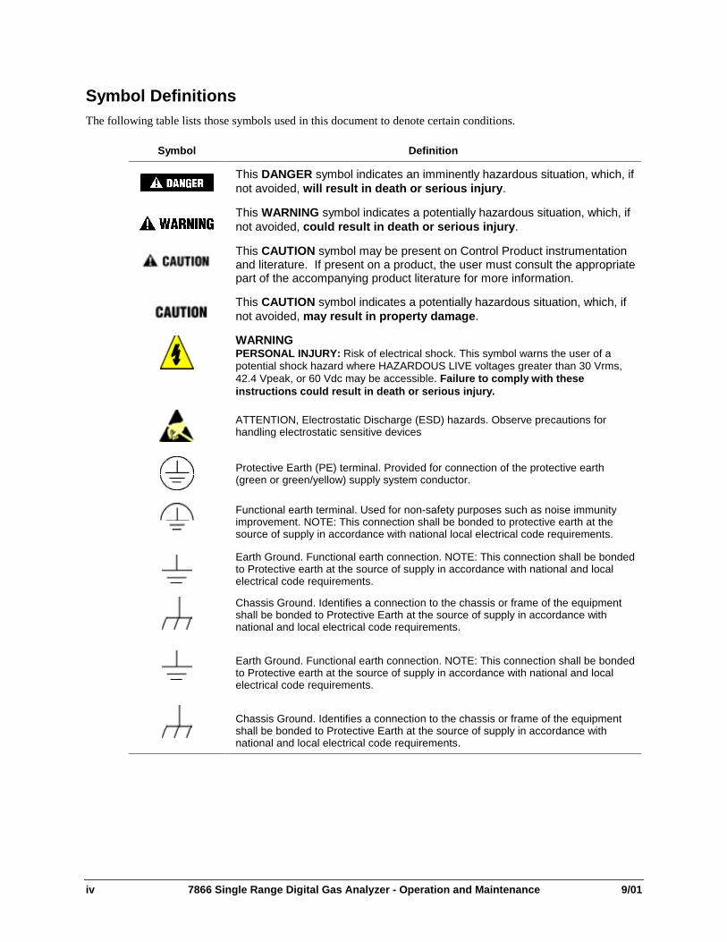
Symbol DefinitionsThe following table lists those symbols used in this document to denote certain conditions.
Symbol Definition
This DANGER symbol indicates an imminently hazardous situation, which, ifnot avoided, will result in death or serious injury.
This WARNING symbol indicates a potentially hazardous situation, which, ifnot avoided, could result in death or serious injury.
This CAUTION symbol may be present on Control Product instrumentationand literature. If present on a product, the user must consult the appropriatepart of the accompanying product literature for more information.
This CAUTION symbol indicates a potentially hazardous situation, which, ifnot avoided, may result in property damage.
WARNINGPERSONAL INJURY: Risk of electrical shock. This symbol warns the user of apotential shock hazard where HAZARDOUS LIVE voltages greater than 30 Vrms,42.4 Vpeak, or 60 Vdc may be accessible. Failure to comply with theseinstructions could result in death or serious injury.
ATTENTION, Electrostatic Discharge (ESD) hazards. Observe precautions forhandling electrostatic sensitive devices
Protective Earth (PE) terminal. Provided for connection of the protective earth(green or green/yellow) supply system conductor.
Functional earth terminal. Used for non-safety purposes such as noise immunityimprovement. NOTE: This connection shall be bonded to protective earth at thesource of supply in accordance with national local electrical code requirements.
Earth Ground. Functional earth connection. NOTE: This connection shall be bondedto Protective earth at the source of supply in accordance with national and localelectrical code requirements.
Chassis Ground. Identifies a connection to the chassis or frame of the equipmentshall be bonded to Protective Earth at the source of supply in accordance withnational and local electrical code requirements.

9/01 7866 Single Range Digital Gas Analyzer - Operation and Maintenance v
Contents
1. INTRODUCTION................................................................................................... 11.1 Overview ........................................................................................................................................ 1
1.2 Sensing Unit ................................................................................................................................... 2
1.3 7866 Digital Controller .................................................................................................................. 4
1.4 Principles of Operation .................................................................................................................. 7
2. SPECIFICATIONS AND MODEL SELECTION GUIDE ........................................ 92.1 Specifications ................................................................................................................................. 9
2.2 Model Selection Guide................................................................................................................. 12
3. INSTALLATION .................................................................................................. 173.1 Overview ...................................................................................................................................... 17
3.2 Sensing Unit Requirements and Location.................................................................................... 17
3.3 Mounting the Sensing Unit .......................................................................................................... 18
3.4 Piping or Tubing Connections ..................................................................................................... 18
3.5 Mounting the 7866 Digital Controller ......................................................................................... 21
3.6 Wiring Between Sensing Unit and Digital Controller ................................................................. 24
3.7 Checklist....................................................................................................................................... 26
4. SET UP MODE.................................................................................................... 274.1 Overview ...................................................................................................................................... 27
4.2 Configuration Tips ....................................................................................................................... 27
4.3 Unit Set Up Group ....................................................................................................................... 28
4.4 Alarms Set Up Group................................................................................................................... 30
4.5 Modbus Communications Set Up Group ..................................................................................... 31
4.6 Calibration Group ........................................................................................................................ 32
4.7 Status Group................................................................................................................................. 32
5. CALIBRATION.................................................................................................... 335.1 Overview ...................................................................................................................................... 33
5.2 Sensing Unit Calibration.............................................................................................................. 33
5.3 7866 Input Calibration ................................................................................................................. 34
5.4 Output Calibration........................................................................................................................ 36
5.5 Security Lockout .......................................................................................................................... 37
5.6 Setting the Alarm Limits.............................................................................................................. 39

vi 7866 Single Range Digital Gas Analyzer - Operation and Maintenance 9/01
6. OPERATION ....................................................................................................... 416.1 Overview ...................................................................................................................................... 41
6.2 Operating Notes ........................................................................................................................... 41
6.3 Operation...................................................................................................................................... 41
7. MAINTENANCE .................................................................................................. 437.1 Routine Maintenance ................................................................................................................... 43
7.2 Parts Replacement........................................................................................................................ 437.2.1 Sensing Unit.......................................................................................................................... 43
7.3 Repacking..................................................................................................................................... 46
7.4 Spare Parts.................................................................................................................................... 47
8. TROUBLESHOOTING ........................................................................................ 498.1 Overview ...................................................................................................................................... 49
8.2 Troubleshooting ........................................................................................................................... 498.2.1 General.................................................................................................................................. 498.2.2 Recalibration......................................................................................................................... 498.2.3 Fault Isolation Tests.............................................................................................................. 518.2.4 Additional Troubleshooting.................................................................................................. 55
9. APPENDIX A – SECURITY BYPASS ................................................................. 579.1 Overview ...................................................................................................................................... 57

9/01 7866 Single Range Digital Gas Analyzer - Operation and Maintenance vii
Tables
Table 1-1 Function of Keys ......................................................................................................................... 5Table 1-2 Relative Thermal Conductivity of Common Gases .................................................................... 7Table 4-1 Configuration Tips .................................................................................................................... 27Table 4-2 Unit Group Function Prompts................................................................................................... 28Table 4-3 Alarms Group Function Prompts .............................................................................................. 30Table 4-4 Modbus Communications Group Function Prompts................................................................. 31Table 4-5 Status Group Function Prompts ................................................................................................ 32Table 5-1 Input Calibration for Range 1 ................................................................................................... 34Table 5-2 Restoring Factory-set Input Calibration Values........................................................................ 35Table 5-3 Output Calibration Procedure ................................................................................................... 36Table 5-4 Entering the Security Code ....................................................................................................... 37Table 5-5 Changing Security Level........................................................................................................... 38Table 5-6 Alarm Adjustment Procedure.................................................................................................... 40Table 7-1 Sensing Unit Cell Assembly Cable Connections ...................................................................... 45Table 7-2 Recommended Spare Parts........................................................................................................ 47Table 8-1 Coarse Zero Adjustment ........................................................................................................... 50Table 8-2 Binary Count Sequence for Coarse Zero Jumper Pattern ......................................................... 50Table 8-3 Coarse-Zero Jumper Pattern...................................................................................................... 51Table 8-4 Troubleshooting Procedures ..................................................................................................... 52

viii 7866 Single Range Digital Gas Analyzer - Operation and Maintenance 9/01
Figures
Figure 1-1 7866 Digital Analyzer................................................................................................................ 1Figure 1-2 Sensing Unit, Showing Removal of Entire Sensing Assembly ................................................. 3Figure 1-3 7866 Digital Controller, Front View ......................................................................................... 5Figure 1-4 Single-Range Gas Analyzer Controller and Display Logic Chart ............................................. 6Figure 3-1 Outline and Mounting Dimensions for Sensing Unit .............................................................. 20Figure 3-2 7866 Digital Controller Dimensions........................................................................................ 22Figure 3-3 Mounting Method for Controller ............................................................................................. 23Figure 3-4 Interconnections Between Digital Controller and Sensing Unit.............................................. 25Figure 7-1 Sensing Unit Mother and Daughter Circuit Cards Parts List .................................................. 44Figure 7-2 Gas Inlet and Outlet Fitting Parts ............................................................................................ 46

Introduction
9/01 7866 Single Range Digital Gas Analyzer - Operation and Maintenance 1
1. Introduction
1.1 OverviewThe 7866 Analyzer consists of three basic components: the sensing unit (transmitter), the control unit(receiver)—both shown in Figure 1-1—and a power supply. The sensing unit is located at the sampling site;the 7866 Digital Controller is arranged for panel mounting in a non-hazardous area.
The sensing unit receives a continuous flow of the binary or multi-component gas mixture, measures theconcentration of the sample gas and transmits an electrical signal to the control unit. The sensing unit isruggedly constructed to meet most environmental conditions and is designed to be mounted up to 1,000 feetfrom the control unit with only a single multi-conductor non-shielded cable connecting the two, resulting ingreater flexibility and lower installation costs.
LOWERDISPLAY
RUNHOLDSET UP
FUNCTION
ALM
DI
RSP
OUT
%100.0RANGE 1
MANUALAUTO
SETPOINTSELECT
Figure 1-1 7866 Digital Analyzer
The control unit receives the output signal from the sensing unit at the sampling site by way of theinterconnecting cable. The control unit is designed for simplified panel-mounting either at the sampling site,if environmental conditions permit, or in a control room. The unit can provide a current output signal to aremote device for monitoring or recording purposes. The control unit is supplied with one or two alarms.When an alarm is detected, the specific relay de-energizes, creating an open circuit that can activate anexternal annunciator or a relay to initiate a shutdown procedure for the process. When power is off thealarm relay is de-energized.

Introduction
2 7866 Single Range Digital Gas Analyzer - Operation and Maintenance 9/01
1.2 Sensing UnitThe 7866 Thermal Conductivity Analyzer’s Sensor Assembly is supplied in an explosion proof housing.The housing consists of a rugged cast aluminum construction that permits reliable operation under adverseambient conditions.
The Sensor Assembly consists of two sections – the cell block assembly and the electronic assembly (Figure1-2).
The Cell Block assembly is constructed of stainless steel with two identical internal cells, the measuring celland the reference cell. The highly stable thermistor is mounted in each cell. These matched thermistors formthe active arms of a bridge circuit; the unbalanced current of the bridge provides the means of measuring therelative ability of the sample and reference gases to conduct the heat away from their respective thermistorsto the cell wall, which is held at a constant temperature.
The reference gas chamber, with inlet and outlet openings drilled into the chamber from the base, can beopened or sealed. All zero-based standard ranges and the 20 % to 50 % H2 Range have air-filled, sealedreference cells. For hydrogen ranges starting above 50 % as well as the 90-100 % oxygen range, a flowingreference is used. The measuring chamber is open to the continuous sample gas flow.
The cells in which the thermistors are mounted are dead-ended so the sample gas enters only by diffusion,minimizing the effect of sample flow variations. In addition, the entire cell-block assembly is maintained ata constant optimum temperature through two heaters and a control thermistor that are located in the cellblock assembly.
The Sensing Unit’s electronics assembly incorporates solid state electrical circuits. These circuits include:
• Current Regulator: supplies the constant current to the thermistor cell bridge circuit.
• Proportional Action Temperature Controller: maintains the entire cell block at a constanttemperature.
• Voltage to Current Converter/Amplifier: its current output is transmitted to the analyzer’sControl Unit.

Introduction
9/01 7866 Single Range Digital Gas Analyzer - Operation and Maintenance 3
91413
12
Rugged threaded cap seals on gasketed housing
Stainless steel handle facilitatesremoval of sensor assembly
Cell-block electronics assembly
Stainless steel cell-block assembly
Inlet and outlet ports to measuringand reference cells
Rugged, general purpose waterproof and dustproofcast-aluminum housing
Inlet and outlet ports for sample gas
Figure 1-2 Sensing Unit, Showing Removal of Entire Sensing Assembly

Introduction
4 7866 Single Range Digital Gas Analyzer - Operation and Maintenance 9/01
1.3 7866 Digital ControllerThe 7866 Digital Controller shown in Figure 1-3 can provide a current output, a digital display of themeasured gas percentage, and up to two alarm circuits. The alarm limits are set using the integral keyboardon the face of the instrument.
The unit also provides access to the calibration settings for the range. The zero and span setting are enteredusing the CALIB group prompts. Zero and span are "live" readings until the FUNCTION key is pressed, atwhich time that displayed value is captured. The ▲/▼ keys can then be used to change the desired value.These values are normally secured from inadvertent or unauthorized tampering using a four-digit securitycode.
If alarms are in use, the 7866 Digital Controller displays the alarm status. The alarms are listed by numberon the left side of the display.
If the alarm is in force, the number “1” or “2 “ will be lit indicating the respective alarm and processviolation. These alarms will de-energize output relays that the user may hardwire to annunciation circuits orto a safety shutdown system depending on the application. Alarm limits are adjusted through the ALARMSSet Up group. The security feature can also secure alarm limits.
Normal power losses, even over extended time periods, will not affect the configuration of the controller.The controller uses a non-volatile memory system to secure the controller’s current configuration andcalibration settings. This will prevent any loss during outages.
The factory calibration constants that can be used with the controller are stored in its nonvolatile memory. Ifa field calibration is lost, you can quickly restore the "factory calibration" and overwrite any previous fieldcalibration. Protection after calibration is available through the LOCKOUT feature.
The controller’s circuit boards are accessible for service and replacement. The modular design permitsselective replacement of circuits as required. The removable chassis eliminates the need to remove orchange any field wiring for a circuit board or controller change.
The rear of the controller has three terminal strips for field wire termination. All field terminations areaccessible from the rear of the controller. Stranded wire of 20 to 22 gauge is recommended. See wiringsection for more specific instructions.
The 7866 Digital Controller features a universal power supply that can be connected to line voltages of90 Vac to 264 Vac or 24 Vac/dc. The line frequency can be 50 hertz or 60 hertz.
Power for the 7866 Sensing Unit is supplied by a separate 30 Volt dc power supply. This power supply isalso utilized by the controller to power its interconnections with the sensing unit.

Introduction
9/01 7866 Single Range Digital Gas Analyzer - Operation and Maintenance 5
LOWERDISPLAY
RUNHOLD
SET UP
FUNCTION
ALM
DI
RSP %100.0
RANGE 1
MANUALAUTO
SETPOINTSELECT
OUT
KeysSee Table 1-1
BargraphDisplays PV value inincrements of 5% of theinput range.Segments turn ON frombottom to top.
Upper Display - six characters• Normal Operation - four digits dedicated to displaying the process variable(Decimal place is selectable to either 1 or 2 places)
• Configuration Mode - displays parameter values or selectionLower Display - eight characters• Normal Operation - displays RANGE 1 or the gas prompt• Configuration Mode - displays the group or function prompt
Annunciators 1 2
ALM - 1 or 2 willbe ON indicatingan alarm conditionexists for therespective alarm.
No otherannunciators areused.
Figure 1-3 7866 Digital Controller, Front View
Table 1-1 Function of Keys
Key Function
SET UP • Places the controller in the Configuration Set Up group select mode. Sequentially displays SetUp groups and allows the FUNCTION key to display individual functions in each Set Up group.
FUNCTION • Used in conjunction with the SET UP key to select the individual functions of a selectedConfiguration Set Up group.
• Pressing this key saves, into nonvolatile memory, any changes made to previous functionvalue or selection.
• Used during field calibration procedure.
▲ • Configuration Mode: Used to scroll through parameter selections or to increase the selectedparameter value.
▼ • Configuration Mode: Used to scroll through parameter selections or to decrease the selectedparameter value.
ChangingValuesQuickly
When changing the value of a parameter, you can adjust a more significant digit in the upperdisplay by holding in one key (▲ or ▼), and pressing the other (▲ or ▼) at the same time. Theadjustment will move one digit to the left. Press the key again and you will move one more digit tothe left.
LOWERDISPLAY
• Used to toggle between RANGE 1 and the Input Type [e.g., PC H2 (Percent Hydrogen)] duringnormal operation.

Introduction
6 7866 Single Range Digital Gas Analyzer - Operation and Maintenance 9/01
Key Function
MANUALAUTO
SETPOINTSELECT
RUNHOLD
• Unused keys
• KEY ERR message will appear in lower display if one of these keys is pressed.
Microampere Signalfrom Sensor
Output SignalProportional to display range0/4-20 mA
Lower Display
RANGE 1Set to Range 1
R1 ZERO = Range 1 Zero
R1 SPAN = Range 1 Span
0% Span Gas(100% background gas)
Range 1 =% Span Gasvs. Background Gas
100% Span Gas(0% background gas)
Select Range
1
Zero and Span Limits
Percentage ofSpan Gas
Upper Display
Selected Range Percentage of Span Gas
Range Alarms
Low
High
Alarm 1
Alarm 2
Figure 1-4 Single-Range Gas Analyzer Controller and Display Logic Chart

Introduction
9/01 7866 Single Range Digital Gas Analyzer - Operation and Maintenance 7
1.4 Principles of Operation
Thermal Conductivity Principles
Although basic thermal conductivity principles need not be included here, it may be appropriate to considerthe following expressions.
Thermal Conductivity of Gas
The thermal-conductivity of a gas mixture is approximately the sum of the products of the mole fractions ofeach gas mixture. Therefore, using the letter K to represent thermal conductivity, a gas mixture of 15 % CO2
in air can be defined by the following expression:
Kmix = 0.85 Kair + 0.15K CO2
Thermal Conductivity of Air
Expressing thermal conductivities in air can be defined by the following expression:
Kair is 1.00 and KCO2 is 0.704. ThereforeKmix = 0.85 x 1 + 0.15 x 0.704 = 0.91.
Temperature Difference
Using a thermistor as the detector in a sample gas and another thermistor in the reference gas, the differencein temperature of these two detectors can be estimated when the thermal conductivities of the gas mixture ofthe sample gas and reference gas are known. This temperature difference can be expressed as follows:
t = Kref – Kmix x (t1-t2)Kmix
Where t1 is the reference thermistor temperature and t2 is the cell-block temperature. The above expressionapplies only when the measuring and reference thermistors are heated to at least 120 °C, which is theminimum temperature for which these thermistors will linearly sense thermal conductivity changes. Itapplies when current input is constant and the heat losses are by thermal conductivity only.
Common Gases
Table 1-2 lists the common gases which can be measured by this method or can be present as components inthe background gas of the mixture being measured. All thermal conductivities are referred to air at 120 °C.
Table 1-2 Relative Thermal Conductivity of Common Gases
Component Thermal Conductivity(K)
Component Thermal Conductivity(K)
Air 1.000 Cl2 0.342
O2 1.028 SO2 0.350
NH3 1.040 H2S 0.540
CH4 1.450 Ar 0.665
He 5.530 CO2 0.704
H2 6.803 H2O 0.771
CO 0.958
N2 0.989

Introduction
8 7866 Single Range Digital Gas Analyzer - Operation and Maintenance 9/01

Specifications and Model Selection Guide
9/01 7866 Single Range Digital Gas Analyzer - Operation and Maintenance 9
2. Specifications and Model Selection Guide
2.1 Specifications
Performance
Accuracy ± 2 % of span (output signal) at reference conditions for binary gas mixtures
Linearity Within ± 2 % of span for most standard ranges. If linearity exceeds ± 2 % a correctioncurve is supplied with the analyzer.
Meter Accuracy: ± 2 % of spanDigital Indication: ± 0.1 %
Repeatability Short term: ± 0.3 % of span
Reproducibility 24 hour: ± 1 % of span
Response Time Maximum, for 4 cfh (2000 cc/min.) flow:For H2; initial, less than 1 second;
63 %: 13 seconds90 %: 23 seconds99 %: 40 seconds
For CO2; Initial, less than 2 seconds;63 %: 24 seconds90 %: 45 seconds99 %: 80 seconds
Maximum Drift Zero: ± 2 % of span/week maximumSpan: ± 2 % of span/week maximum
AmbientTemperatureInfluence
At sensing unit: Depends on range; typically less than 1 % F.S. over entiretemperature range
At control: ± 0.01 % per °C (± 0.005 % of span per °F)
AtmosphericPressure Influence
± 0.1 % of span per inch H2O (± 0.05 % per mm Hg)
Sample Flow RateInfluence
Less than ± 0.5 % of span over flow range of 0.2 cfh to 4 cfh (100 cc/min to2000 cc/min)
Line VoltageInfluence
Maximum 0.02 % of span for each 1 % change of line voltage

Specifications and Model Selection Guide
10 7866 Single Range Digital Gas Analyzer - Operation and Maintenance 9/01
Specifications (continued)
Operating
Measuring Range One range, as specified. For standard ranges, see Selection Guide Table in theModel Selection Guide.
Output Ranges 0-20 mA maximum load: 800 ohm4-20 mA maximum load: 800 ohm
0/4-20 mA Output 0/4 mA at low range limit20 mA at high range limit
Alarm Outputs Two alarms are available; each uses an SPDT electromechanical relay.
Alarm Relay Contacts RatingResistive Load: 5 amps @ 24 Vdc or 120 Vac or 240 VacInductive Load: 50 VA
Outputs Two relay outputs for Alarm 1 and Alarm 2One current output that represents value of PV.
SampleRequirements
Sample Flow: 0.2 cfh to 4.2 cfh (100 cc/min to 2000 cc/min)Sample Pressure: 37 mm Hg (20” H2O) minimum (with filter and flowmeter)
Reference GasRequirements
None required, except for ranges 095000, 098000, 500006, 512000, and 516000;these require pure hydrogen reference gas flow, 0.02-0.2 cfh (10-100 cc/min).
AmbientRequirements
Relative Humidity: 90 % maximumTemperature Range: –10 °C to +50 °C (14 °F to 122 °F)Storage Temperature: 70 °C maximum (158 °F)
PowerRequirements
Control Unit only: Universal supply 90 Vac to 264 Vac (consumption 18 VA maximum)or 24 Vac/dc (consumption 12 VA maximum); 50 Hz to 60 Hz
MaterialsContacting SampleGas
Sample contacts 316 stainless steel, Buna N, Teflon, glass and Viton
Connections Sample inlet and outlet: ¼” OD tubing (compression fittings supplied)Reference gas inlet and outlet: ¼” OD tubing (compression fittings supplied)Electrical power inlet: Opening for ½” conduit (control unit only)Sensing unit power inlet (24 Vdc from control unit): ½” NPT (female conduit)
Communications(optional):
Link Characteristics: Two-wire multi-drop Modbus RTU protocol, 15 drops maximumor up to 31 drops for shorter link lengthDistance: 4000 feet maximumBaud Rate: 2400 baud, 4800 baud, 9600 baud, or 19.2K baud selectableData Format: Floating point or integerParity: Selectable odd or even

Specifications and Model Selection Guide
9/01 7866 Single Range Digital Gas Analyzer - Operation and Maintenance 11
Specifications (continued)
PhysicalSpecifications
Sensing Unit:Weight: Explosion proof – 8.5 kg (18-3/4 lb.)Dimensions: Explosion proof – Approximately 150 mm x 150 mm x 325 mm
(6 in. x 6 in. x 12-3/4 in.)
Control Unit:Weight: 1.3 kg (3 lb.)Dimensions: Bezel: 96 mm H x 96 mm W (3.78” H x 3.78” W)
Case: 92 mm H x 92 mm W x 192 mm D(3.62” H x 3.62” W x 7.55” D)
Standards –Sensing Unit
Explosion-proof sensing unit: Designed to meet NEMA 7, Class 1, Division 1, GroupsA, B, C and D
This product is in conformity with the protection requirements of the followingEuropean Council Directives: 73/23/EEC, the Low Voltage Directive, and 89/336/EEC,the EMC Directive. Conformity of this product with any other “CE Mark” Directive(s)shall not be assumed.
Product Classification: Class I: Permanently connected, panel-mounted IndustrialControl Equipment with protective earthing (grounding).(EN61010-1).
Enclosure Rating: Panel-mounted equipment, IP 00. This controller must bepanel-mounted. Terminals must be enclosed within thepanel. Front panel IP 65 (IEC 529).
Installation Category(OvervoltageCategory):
Category II: Energy-consuming equipment supplied from thefixed installation, local level appliances, and IndustrialControl Equipment. (EN61010-1)
Pollution Degree: Pollution Degree 2: Normally non-conductive pollution withoccasional conductivity caused by condensation. (Ref. IEC664-1)
EMC Classification: Group 1, Class A, ISM Equipment (EN55011, emissions),Industrial Equipment (EN50082-2, immunity)
Method of EMCAssessment:
Technical File (TF)
Standards – ControlUnit
Declaration ofConformity:
51309602-000
Miscellaneous Analyzer temperature: Sensing unit thermostated at 50 °C (122 °F)
Environmental and Operating Conditions
Temperature Range Typical: 15 °C to 55 °C (58 °F to 131 °F)Extreme: 0 °C to 55 °C (32 °F to 131 °F)
Relative Humidity Typical: 10 % to 90 %Extreme: 5 % to 90 %
Vibration Typical: 0.1 g acceleration between 0 Hz and 70 HzExtreme: 0.5 g acceleration between 0 Hz and 200 Hz

Specifications and Model Selection Guide
12 7866 Single Range Digital Gas Analyzer - Operation and Maintenance 9/01
2.2 Model Selection Guide
51-52-16-78Issue 1
InstructionsSelect the desired key number. The arrow to the right marks the selection available.Make one selection from Tables using the column below the proper arrow.A dot ( ) denotes unrestricted availability.
Key Number I II III IV V_ _ _ _ _ _ _ _ - _ - _ - _ _ _ - _ - _ _ _ _ _ _ -
VI VII VIII
_ - _ - _ _ _
KEY NUMBER Selection AvailabilityDescription
7866 Digital Thermal Conductivity Gas Analyzer consisting of: 07866DO2a) 07866DS2 Sensor Assembly (includes housing)
b) 07866DC2 Digital Control Unit
7866 Replacement Digital Control Unit Only 07866DC27866 Replacement Sensor Assembly - 2 Port ( Electronics Only) 07866SS27866 Replacement Sensor Assembly - 4 Port ( Electronics Only) 07866SS4
TABLE I - SENSOR POWER SUPPLY/LINE VOLTAGENone 0Input Voltage 105 - 125 VAC, 50 - 400 Hz. 2Input Voltage 210 - 250 VAC, 47 - 520 Hz. 4
TABLE II - OUTPUT (PV RANGE)None 00-20 mA 14-20 mA 2
TABLE III - COMMUNICATIONSNone 000RS422/485/MODBUS 101
TABLE IV - BACKGROUND GAS (Note: On replacement control unit chassis, selection must be same as selection on original unit)Air, N2, CO2, or O2 where component being measured is % H2 1 j j j jAir, N2, or O2 where component being measured is % CO2 2 k k kH2 where component being measured is % O2 4 l l l
Air where component being measured is % He 5 m m m

Specifications and Model Selection Guide
9/01 7866 Single Range Digital Gas Analyzer - Operation and Maintenance 13
0 0 0 07 7 7 78 8 8 86 6 6 66 6 6 6D D S S
TABLE V - RANGE (Note: On replacement control unit chassis, O C 2 4selection must be the same as selection on original unit) Selection 2 2 2 4When measuring % H2 in Air, N2, or O2; % H2 @:
0-1 001000 c
0-2 002000 c
0-5 005000 c
0-10 010000 c
0-15 015000 c
0-20 020000 c
0-30 030000 c
0-75 575000 c
0-100 503000 c c
50-100 103000 h
80-100 080000 h
85-100 516000 h
90-100 506000 h
95-100 095000 h
98-100 098000 h
60-80 515000 c
40-80 548000 c
45-55 514000 c
20-50 050000 cWhen measuring % CO2 in Air, N2, or O2; % CO2 @:
0-10 010000 c
0-15 015000 c
0-20 020000 c
0-30 030000 c
0-40 518000 c
0-100 519000 cWhen measuring 0-100 % H2 in CO2 111000 c
When measuring 70-100 % He in Air 510000 hWhen measuring 95-100 % O2 in H2 090000 c
Special application: 0-75% dissociated ammonia 075000 c c
Table VI - SENSOR UNITNoneSealed Reference - 2 Port Explosion ProofFlowing Reference - 4 Port Explosion Proof
037

Specifications and Model Selection Guide
14 7866 Single Range Digital Gas Analyzer - Operation and Maintenance 9/01
0 0 0 07 7 7 78 8 8 8
6 6 6 66 6 6 6
D D S S
O C 2 4
TABLE VIII - OPTIONS Selection 2 2 2 4
None 000Linen Tags: 15 characters max. On each of three lines: 206
Specify legend. One mounted on control Unit. One on Sensing UnitStainless Steel Tag: 208
15 characters max. On each of three lines:Specify legend. One mounted on control Unit. One on Sensing Unit
ACCESSORY PARTSDescription Part NumberPower Supply - Input Voltage 105-125VAC, 50-400 Hz 51450915-501Power Supply - Input Voltage 210 -250VAC, 47-520 Hz 51450915-502DIN Adaptor Plate 30755223-002
RESTRICTIONSAvailable Only With Not Available With
Restrictions Letter Table Selection Table Selectionc VI 3h
090000, 510000,518000, 519000
010000, 01500020000, 030000
518000, 519000l V 090000
m V 510000
j
k V
VVI 7

Specifications and Model Selection Guide
9/01 7866 Single Range Digital Gas Analyzer - Operation and Maintenance 15
SELECTION GUIDE (Note 1)Single % Range Measurement Table IV Table V Table VI(no price adder) Component Background Background Range Sensing
Gas Code Unit0-1 % H2 Air or N2 1 001000 3
or O2
0-2 0020000-5 0050000-10 0100000-15 0150000-20 0200000-30 0300000-75 5750000-100 503000 350-100 103000 780-100 080000 785-100 516000 790-100 506000 795-100 095000 798-100 098000 760-80 515000 340-80 548000 345-55 514000 320-50 050000 30-10 % CO2 Air or N2 2 010000 3
0-15 or O2 015000
0-20 0200000-30 0300000-40 5180000-100 5190000-100 % H2 CO2 1 111000 3
70-100 % He Air 5 510000 795-100 % O2 H2 4 090000 30-75 dissociated ammonia % H2 N2 1 075000 3
Triple Range: For hydrogren cooled generator applications, See GA-21 for pricing on7866DHH2 and GA-3 for Optional 7872 Sampling System.
NOTES:1. This Selection Guide is included to assist in the model selection process for 7866 Digital Thermal
Conductivity Gas Analyzers.

Specifications and Model Selection Guide
16 7866 Single Range Digital Gas Analyzer - Operation and Maintenance 9/01

Installation
9/01 7866 Single Range Digital Gas Analyzer - Operation and Maintenance 17
3. Installation
3.1 OverviewThis section describes the installation requirements and procedures for the Sensing Unit and the DigitalController.
3.2 Sensing Unit Requirements and Location
Location
Locate the sensing unit as close as possible to the sampling probe to minimize response lag. This should beat a point in the gas stream which best represents the true gas composition. An ac power line is not required.The sensing unit can be located in a protected outdoor area. The housing is watertight; but it should not beexposed to direct rays from the sun. Ambient temperature must not go above 50 °C (122 °F) or below –10 C (14 °F).
Connections
Provide a three-conductor copper-wire cable (four-conductor if a solenoid calibrate valve is used) toprovide the connections between the sensing unit and the 7866 Digital Controller. The required wire sizefor each conductor is listed in Section 2.1 according to cable length. An adapter is supplied to terminate 1/2inch threaded conduit and connect to the sensing unit watertight housing. The explosion-proof housing istapped for 1/2 NPT conduit.
Clearance
Provide at least 12 inches clearance above the top of the sensing unit to allow the internal assembly to beremoved for servicing. Allow appropriate space below the sensing unit for 1/4 inch or 6 mm inlet and outlettubing connections. Position the sensing unit on a vertical surface with the inlet and outlet fittings at thebottom. Allow space at the right-hand opening for the solenoid calibrate valve, which, if supplied, is to bemounted here.
Sampling System
Provide a sampling system to deliver a clean and relatively dry sample at a rate of 100 to 2000 cc perminute. The sample should be free of dust.
Calibrating Gases
Provide a source of calibrating gases; e.g., cylinders of compressed zero gas and span gas with pressureregulating valves on each. In general, a zero gas contains all gas components in the sample stream exceptthe measured gas. For suppressed-zero ranges, zero gas contains measured gas at or slightly above the low-end value. Concentrations should be those normally present in the stream. A span gas contains all of thegases in the sample stream at expected concentrations with measured gas concentration accurately analyzed.Concentration of water (vapor) in the calibrating gas should be the same as that in the background gas.Therefore, a gas saturator or dryer may be required.

Installation
18 7866 Single Range Digital Gas Analyzer - Operation and Maintenance 9/01
Reference Gas
Provide a source of reference gas, if required. If hydrogen or helium, supply at 0.02 cfh to 0.2 cfh(10 cc/min to 100 cc/min). Vent to atmospheric pressure. (If hydrogen, vent to a safe ventilating system.). Ifflowing air is required, supply at 0.5 cfh to 2.0 cfh (250 cc/min to 1000 cc/min). Vent to atmosphericpressure.
3.3 Mounting the Sensing Unit
Explosion-Proof Housing
EXPLOSION-PROOF SENSING UNIT REQUIREMENTS• Always use conduit for electrical wiring and follow special installation procedures.• Make certain fully qualified personnel make this installation and all local regulations are observed.Failure to comply with these instructions could result in fire caused by explosion inside the housing.
The sensing unit is designed as explosion-proof. Dimensions for this unit are shown in Figure 3-1.Electrical conduit must be used for all wiring and the openings are fitted for 1/2-inch conduit.
Mount the explosion-proof sensing unit in accordance with Figure 3-1.
3.4 Piping or Tubing Connections
Inlet and Outlet Connections
The O-ring type compression fittings in the base of the sensing unit will accept plastic or metal tubinghaving an O.D. between 0.236 inches (6 mm) and 0.255 inches (6.5 mm). Make inlet and outlet connectionsin accordance with Figure 3-1.
Types of Tubing
Any metal and most plastic tubing can be used provided it is chemically compatible with the sample gas.Avoid the use of plasticized PVC or other soft tubing at the sensing-unit compression fittings and do not usetubing having an inside diameter less than 4 mm.
Outlet Line Connection
To maintain the analyzer cell at constant pressure under various flow conditions, the outlet line must be lessthan two meters (six feet) long and should exit to atmospheric pressure. No restrictions (other than aRotameter-type flowmeter) can be used in this line. If a longer vent line is required, use larger diametertubing, e.g., 12 mm (1/2”) O.D.

Installation
9/01 7866 Single Range Digital Gas Analyzer - Operation and Maintenance 19
Making Connections
CONNECTION DAMAGE• Excessive tightening on metal tubing may damage the O-ring.• Excessive tightening on plastic tubing may restrict the opening.Failure to comply with these instructions may result in product damage.
Step Action
1 Cut the tubing squarely and remove all burrs, loosen the compression nut.
2 Then push the tubing firmly into fitting until it slips through the O-ring and seats against the metal.
3 Tighten the compression nut by hand; then turn it about 1/8 turn with a wrench. If the entire fittingassembly turns, use a back-up wrench.
4 If a good seal does not result, remove the compression nut and slide it onto the tubing, take out thesmall O-ring and slip it on the tubing, then assemble the fitting.

Installation
20 7866 Single Range Digital Gas Analyzer - Operation and Maintenance 9/01
Clearance required for sensor removal2509.84
1656.50
92 max.3.625 max.
1485.82
9.35DIA.
562.20
*
114 DIA4.48 DIA
1405.51
1546.06
803.14
1666.53
1566.14
SampleInlet
7866 Thermal Conductivity Analyzer(4 port)
1/2"NPT
12.472
SampleOutlet
ReferenceOutlet
ReferenceInlet
562.20
SampleInlet
SampleOutlet
Front View
Left Side View
Internal 4 pt.Terminal Board*6-32 Screws
RemovableThreadedCover
*For 1/4” O.D. or 6 mm O.D.Metal or Plastic Tubing
NOTE:1. Weight of unit is approximately 18-3/4 lb. (8.5 kg)2. Wiring diagram is ID-2071-356.
Figure 3-1 Outline and Mounting Dimensions for Sensing Unit

Installation
9/01 7866 Single Range Digital Gas Analyzer - Operation and Maintenance 21
3.5 Mounting the 7866 Digital Controller
Introduction
The 7866 Digital Controller can be mounted on a panel using the mounting kit supplied. Adequate spacemust be available at the back of the panel for installation and servicing activities.
The controller is considered “rack and panel mounted equipment” per the following safety standards:For US, ANSI/ISA S82-1994For Canada, CAN/CSA – C22.2 No. 1010.1-92For Europe, EN610101-1
Conformity with these standards requires the user to provide adequate protection against a shock hazard. The usershall install this controller in an enclosure that limits OPERATOR access to the rear terminals.
If the controller is used in a manner not specified by Honeywell, the protection provided by the equipment may beimpaired.
Overall Dimensions
Figure 3-2 shows the overall dimensions for mounting the 7866 Controller.

Installation
22 7866 Single Range Digital Gas Analyzer - Operation and Maintenance 9/01
Panel Cutout 96 3.780
24 0.945
Max PanelThickness 10
0.394Max (2)
5.82147.3
21.6
0.850
0.093 2.4 with optional
rear cover
90.73.57
+0.008 92 3.622 +0.03
-0.0
-0.0
+0.008 92 3.622 +0.03
-0.0
-0.0
96 3.780
LOWERDISPLAY
RUNHOLD
SET UP
FUNCTION
ALM
DI
RSP %
MANUALAUTO
SETPOINTSELECT
OUT
1 2
Figure 3-2 7866 Digital Controller Dimensions

Installation
9/01 7866 Single Range Digital Gas Analyzer - Operation and Maintenance 23
Mounting Method
Figure 3-3 shows you the mounting method of the 7866 Controller.
Panel
22605
Figure 3-3 Mounting Method for Controller
Controller Mounting Procedure
Refer to Figure 3-3 and follow the procedure given below to mount the 7866 Controller.
Step Action
1 Mark and cut out the controller hole in the panel according to the dimension information in Figure3-2.
2 Remove the screw cover and loosen the screw on the front of the controller. Pull the chassis out ofthe case.
3 Orient the case properly and slide it through the panel hole from the front.
4 Remove the mounting kit from the shipping container, and install the kit as follows:
• Install the screws into the threaded holes of the clips.
• Insert the prongs of the clips into the two holes in the top and bottom of the case.
• Tighten both screws to secure the case against the panel.
• Carefully slide the chassis assembly into the case, press to close and tighten the screw. Replacethe screw cover.

Installation
24 7866 Single Range Digital Gas Analyzer - Operation and Maintenance 9/01
3.6 Wiring Between Sensing Unit and Digital Controller
Wiring Connections at the Sensing Unit
Step Action
1 After the sensing unit is mounted, carefully remove the top housing by turning it counterclockwise.(Loosen the set screw.)
2 Two openings are provided for cable entrance; make certain the plug screw is tightened firmly intothe unused right-hand opening.
3 Use 1/2 NPT threaded electrical conduit, and mount the special adapter fitting supplied with theanalyzer.
4 Wire as shown in Figure 3-4.
EXPLOSION-PROOF SENSING UNIT REQUIREMENTS• Always use conduit for electrical wiring and follow special installation procedures.• Make certain fully qualified personnel make this installation and all local regulations are observed.Failure to comply with these instructions could result in fire caused by explosion inside the housing.

Installation
9/01 7866 Single Range Digital Gas Analyzer - Operation and Maintenance 25
Wiring Connections at the Digital Controller
The output signal from the 7866 Digital Controller can be configured as a 4-20 milliampere signal or a 0-20milliampere signal. This signal is used to drive a recording device or to report to a DCS or PLC. The signalwill proportionately reflect the percentage of measured gas. Typically, the signal will be at minimum value,(0 mA or 4 mA) when the display reads Zero (“0.0”). The signal will be at 20 millamperes when the displayreads full-scale percentage. The signal is wired in series with a 250-ohm dropping resistor to produce astandard 0-5 volt or 1-5 volt input signal at the receiving device. The analog output can support a totalresistive load of 800 ohms at maximum.
_+
12
13
14
9
Sensing UnitTerminal Strip
(viewed from top)
30 Vdc/30 Watt Power SupplyModel Number B30GT110120 Vac/60 Hz Input Power
230 Vac/50 Hz Version OptionModel Number B30GT110-230
Digital Controller
250 ohmResistor
1
2
3
4
5
6
7
8
9
10
11
12
13
14
15
16
17
L1/H
L2/N
22
23
24
25
26
27
SHIELD
RX+/TX+
RX-/TX-
PV OUT +
PV OUT -
ALM2
ALM1SENSOR IN+
SENSOR IN -
Figure 3-4 Interconnections Between Digital Controller and Sensing Unit

Installation
26 7866 Single Range Digital Gas Analyzer - Operation and Maintenance 9/01
3.7 Checklist
Check # Action
1 Check all wiring and piping. Make certain all fittings are tight. Replace the top bell housing onthe sensing unit and tighten the set screw, if provided. No operating checks or settings arerequired in the sensing unit.
2 Shut off or vent the gas flow at the sampling system to make sure sample will not flow into theanalyzer during start-up.
3 During calibration, it is necessary to read out the analyzer measurements. A milliammeter isused for verification of the readings. The meter should be wired in series with the signal wirebetween terminal 12 of the sensor and terminal 26 of the 7866 Digital Controller.
The test meter used, whether for voltage or current output, should be a digital voltmeter or a millivoltpotentiometer for best accuracy. It should have an input impedance greater than 2000 ohms.
• Do not open the bell housing of the sensing unit unless the power source is disconnected. Then loosen the setscrew to permit housing cover to be turned.
Failure to comply with these instructions could result in death or serious injury.

Set Up Mode
9/01 7866 Single Range Digital Gas Analyzer - Operation and Maintenance 27
4. Set Up Mode
4.1 OverviewThis section describes the steps to configure the 7866 Controller for your application.
4.2 Configuration Tips
Introduction
Table 4-1 lists some tips that will help you enter data more quickly.
Table 4-1 Configuration Tips
Function Tip
Displaying Groups Use the SET UP key to display the Set Up groups.
DisplayingFunctions
Use the FUNCTION key to display the individual parameters under each group. The promptsare listed in the order they appear in each group.
Scrolling If the SET UP key is held in, the Group prompts scroll continuously at a rate of once every2/3 of a second.
Holding in either the ▲ or ▼ key will increase the scroll rate to once every 1/3 of a second inthe forward or reverse direction while viewing Group prompts.
Timing Out fromSet Up Mode
If you are in Set Up mode and do not press any keys for 30 seconds, the controller will timeout and revert to normal operation.
Key Error When a key is pressed and the prompt "KEY ERROR" appears in the lower display, it will befor one of the following reasons:
• Parameter is not available
• Not in Set Up mode, press SET UP key first
• Key not available for use in 7866 Controller

Set Up Mode
28 7866 Single Range Digital Gas Analyzer - Operation and Maintenance 9/01
4.3 Unit Set Up Group
Function Prompts
Table 4-2 lists all the function prompts in the Unit Set Up group.
Table 4-2 Unit Group Function Prompts
Function Prompt(Lower Display)
Function Name Selections or Range of Setting(Upper Display)
FactorySetting
SECURITY Security Code 0000 to 9999 0
LOCKOUT Configuration Lockout NONE – Permits changes to all functions.
CALIB – Calibration group functions arehidden from view.
UNIT – Parameters in the Unit Set Up groupcannot be changed, but the Alarms andCommunications group parameters arechangeable. (Calibration parameters cannotbe seen.)
VIEW – All parameters are read only.(Calibration parameters cannot be seen.)
NONE
TYPE Analyzer Range Type SINGLE – Read only SINGLE
Sensor Input Types: Factory-configured input type, as ordered.This parameter is Read only.
The range chosen selects the range used forinput, alarms, and outputs.
The following is a list of possible input types.You will see only the one that was ordered.
Set asordered
PC H2 Percent Hydrogen 0-10-20-50-100-150-200-300-750-10050-10080-10085-10090-10095-10098-10060-8040-8045-5520-50

Set Up Mode
9/01 7866 Single Range Digital Gas Analyzer - Operation and Maintenance 29
Function Prompt(Lower Display)
Function Name Selections or Range of Setting(Upper Display)
FactorySetting
PC CO2 Percent Carbon Dioxide 0-100-150-200-300-400-100
H2in AIR Hydrogen in Air 0-100
H2in CH4 Hydrogen in Methane 50-100
HEin AIR Helium in Air 70-100
CH4in H2 Methane in Hydrogen 0-30
CH4inAIR Methane in Air 5-15
O2in H2 Oxygen in Hydrogen 95-100
H2in NH3 Hydrogen in Ammonia 0-75
CUR OUT PV Output Type Selection 4-20MA0-20MA
4-20MA
PWR FREQ Input Frequency Selection 60 HZ50 HZ
60 HZ
DECIMAL Decimal Point Location XXX.X – One decimal placeXX.XX – Two decimal places
XXX.X

Set Up Mode
30 7866 Single Range Digital Gas Analyzer - Operation and Maintenance 9/01
4.4 Alarms Set Up Group
Function Prompts
Table 4-3 lists the function prompts in the Alarms Set Up group. Refer to Section 5.6 Setting the AlarmLimits for the alarm adjustment procedure.
Table 4-3 Alarms Group Function Prompts
Function Prompt(Lower Display)
Function Name Selections or Range of Setting(Upper Display)
FactorySetting
ALARM1LO Alarm 1 Setpoint, low alarm type Value in percent
Depends on the sensor input typeselected. The setpoint range limit is setinternally to that of the input type.
Lower limitof selected
inputrange
ALARM2HI Alarm 2 Setpoint, high alarm type Value in percent
Depends on the sensor input typeselected. The setpoint range limit is setinternally to that of the input type.
Upper limitof selected
inputrange
HYSTERiS Alarm Hysteresis 0 to 100.0 0.5

Set Up Mode
9/01 7866 Single Range Digital Gas Analyzer - Operation and Maintenance 31
4.5 Modbus Communications Set Up Group
Introduction
This option allows the controller to be connected to a host computer via the Modbus protocol.
Function Prompts
Table 4-4 lists all the function prompts in the Modbus Communications Set Up group.
Table 4-4 Modbus Communications Group Function Prompts
Function Prompt(Lower Display)
Function Name Selections or Range of Setting(Upper Display)
FactorySetting
Com ADDR Communications StationAddress
1 to 99
This is a number that is assigned to a controllerthat is to be used with the communications option.
1
BAUD Baud Rate 19200960048002400
This is the transmission speed in bits per second.
4800
WS FLOAT Communications MessageIEEE Byte Order
FP B – Floating point big endian (Bytes 0,1,2,3)
FP BB – Floating point big endian with byte-swapped (Bytes 1,0,3,2)
FP L – Floating point little endian(Bytes 3,2,1,0)
FP LB – Floating point little endian with byte-swapped (Bytes 2,3,0,1)
FP B
DUPLEX Duplex Operation HALF – 2-wire communicationsFULL – 4-wire communications
HALF
TX DELAY Transmission Delay 0 to 500
Delay time (in milliseconds) between receivingand sending messages.
0

Set Up Mode
32 7866 Single Range Digital Gas Analyzer - Operation and Maintenance 9/01
4.6 Calibration Group
Calibration Data
Refer to Section 5 Calibration for complete calibration information and instructions.
4.7 Status Group
Status Test Data
Table 4-5 lists all the function prompts in the Status group. All prompts are read-only and provide thestatus of the background diagnostic tests.
Table 4-5 Status Group Function Prompts
Function Prompt(Lower Display)
Function Name Read Only Displays(Upper Display)
VERSION Software Version 7866_n
The first number set (7866) details the unit class as the7866 product and the next number set gives the softwareversion.
RAM TEST Status of RAM test performed inbackground
PASS or FAIL
If status was FAIL, cycle power to see if error clears. Ifproblem persists, the unit is bad and should be replaced.
CONFTEST Status of ConfigurationChecksum test performed inbackground
PASS or FAIL
If status was FAIL, completion of test results inre-computation of checksum and a new status of PASS. Allconfiguration parameters should be rechecked foraccuracy.
CAL TEST Status of Working Calibrationtest performed in background
PASS or FAIL
If status was FAIL, completion of test results inre-computation of CRC value. All calibration of inputs andoutputs should be verified for accuracy.

Calibration
9/01 7866 Single Range Digital Gas Analyzer - Operation and Maintenance 33
5. Calibration
5.1 OverviewThe 7866 analyzer is calibrated at the factory prior to shipping but it must be field-calibrated prior tooperation. The input calibration procedure includes:
• setting zero for range 1,
• setting span for range 1,
• field-calibrating the current output(s),
• entering a security code,
• changing the security level, and
• setting alarm limits.
5.2 Sensing Unit Calibration
• Do not open the bell housing of the sensing unit unless the power source is disconnected. Then loosen the setscrew to permit housing cover to be turned.
• Before making any test with power applied to the sensing unit, either remove the sensing unit to a non-hazardous area or verify that the atmosphere is free from combustible gases.
Failure to comply with these instructions could result in death or serious injury.

Calibration
34 7866 Single Range Digital Gas Analyzer - Operation and Maintenance 9/01
5.3 7866 Input Calibration
Range 1: Span or Measured Gas as a Percentage of the Background Gas
Range 1 is used to indicate the percentage of span gas compared to the background gas. As the span gas isintroduced, the display will progress from the low range limit to the upper range limit. The values of thedisplay limits will vary based on the model number and selected application.
Table 5-1 Input Calibration for Range 1
Step Press Action
1 Connect the zero-calibration gas source to the sensor.
2 SET UP until you see:Upper Display: CALIBRLower Display: RANGE 1
3 FUNCTION You will see:Upper Display: DISABL (default selection)Lower Display: RANGE 1
4 ▲ or ▼ Select CALIB to begin manual calibration procedure for Range 1.
5 FUNCTION You will see R1 ZERO in the Lower Display.The value shown in the Upper Display is a "live" reading. Wait until the valuebecomes stable.
6 FUNCTION Captures the displayed value. The display will blink once indicating that you canuse the ▲ and ▼ keys to change to the desired zero value. (This ties the internalcounts processed for the input conversion to the desired value for Zero.)
7 FUNCTION Saves Range 1 ZERO data.
You will see R1 SPAN in the Lower Display.
Connect the span-calibration gas source to the sensor. The value shown in theUpper Display is a "live" reading. Wait until the value becomes stable.
8 FUNCTION Captures the displayed value. The display will blink once indicating that you canuse the ▲ and ▼ keys to change to the desired span value. (This ties the internalcounts processed for the input conversion to the desired value for Span.)
9 FUNCTION Saves Range 1 SPAN data and processes the calibration calculations.
If, after the Zero or Span "live" value has stabilized, no change is made, you should still perform the same key-presssequences. For example, if in Step 5 you make no change to the displayed value, continue to Step 7 by pressing theFUNCTION key twice.

Calibration
9/01 7866 Single Range Digital Gas Analyzer - Operation and Maintenance 35
Restoring Factory-set Input Calibration
A field calibration will overwrite any previous calibration values. However, the initial factory-set inputcalibration parameters can be restored, if desired, using the procedure in Table 5-2.
Table 5-2 Restoring Factory-set Input Calibration Values
Step Press Action
1 SET UP until you see:Upper Display: CALIBRLower Display: RANGE 1
2 FUNCTION You will see:Upper Display: DISABL (default selection)Lower Display: RANGE 1
3 ▲ or ▼ Select RESTOR to restore factory calibration for desired Range inputparameters.
4 FUNCTION Saves data to the factory-set values.

Calibration
36 7866 Single Range Digital Gas Analyzer - Operation and Maintenance 9/01
5.4 Output Calibration
Introduction
You can calibrate the controller so that the output provides the desired milliampere output when readthrough a meter connected to the desired output terminals.
Before doing an output calibration, make sure the PV Current Output Type (CUR OUT) selection in the Unit Set Upgroup (Table 4-2) is configured properly for either 4-20 mA or 0-20 mA. This selection must agree with what you aremeasuring for the output current to be calibrated correctly.
Table 5-3 Output Calibration Procedure
Step Press Action
1 Connect a milliammeter, with whatever accuracy is required, capable ofmeasuring 0 to 20 milliamps, to terminals 16 and 17 for PV outputs.
2 SET UP until you see:Upper Display: CALIBRLower Display: CURRENT
3 FUNCTION You will see ZERO VAL in the Lower Display.
A four-digit value appears in the Upper Display. Use the ▲ and ▼ keys to changethe value until the milliampere output, on the meter, is at the desired reading(4 mA or 0 mA).
5 FUNCTION Saves the ZERO VAL data.
You will see SPAN VAL in the Lower Display.A four-digit value appears in the Upper Display. Use the ▲ and ▼ keys to changethe value until the milliampere output, on the meter, is at the desired reading(20 mA).
6 FUNCTION Saves the SPAN VAL data and terminates the calibration procedure.
A field calibration will overwrite the manufacturing values. You cannot restore the factory-set outputcalibration.

Calibration
9/01 7866 Single Range Digital Gas Analyzer - Operation and Maintenance 37
5.5 Security Lockout
Introduction
The LOCKOUT feature in the 7866 Controller inhibits changes to certain functions or parameters byunauthorized personnel. There are three different lockout levels:
NONE Allows changes to all functions and parameters.
CALIB Calibration group functions are hidden from view.
UNIT Parameters in Unit group cannot be changed.
VIEW All parameter values are read only and calibration is not permitted.
Entering a Security Code
The level of keyboard lockout may be changed in the Set Up mode. However, knowledge of a four-character security code number [0000 (no security) to 9999] may be required to change from one level oflockout to another. When a controller leaves the factory it has a security code of 0, which permits changingfrom one lockout level to another without entering any other code number.
If you require the use of a security code, select a number from 0001 to 9999 and enter it when the lockoutlevel is configured as NONE. Thereafter, you will need that selected number to change the lockout levelfrom something other than NONE.
Table 5-4 Entering the Security Code
Step Press Action
1 SET UP until you see:Upper Display: SETUPLower Display: UNIT
2 FUNCTION You will see SECURITY in the Lower Display.
3 ▲ or ▼ Enter a four-digit number in the upper display (0001 to 9999).
This will be your security code.
4 FUNCTION Saves the security code to nonvolatile memory.

Calibration
38 7866 Single Range Digital Gas Analyzer - Operation and Maintenance 9/01
Changing Security Level
If the LOCKOUT feature has been set to anything other than NONE and a security code has been entered,you will have to change the LOCKOUT level to NONE before calibrating.
Table 5-5 Changing Security Level
Step Press Action
1 SET UP until you see:Upper Display: SETUPLower Display: UNIT
2 FUNCTION You will see SECURITY in the Lower Display.
3 ▲ or ▼ to enter the four-digit security code number (0001 to 9999)
If the security code is unknown, see Appendix A – Security Bypass.
4 FUNCTION You will see LOCKOUT in the Lower Display.
5 ▲ or ▼ Select NONE.
6 FUNCTION Saves selection to nonvolatile memory.

Calibration
9/01 7866 Single Range Digital Gas Analyzer - Operation and Maintenance 39
5.6 Setting the Alarm LimitsEach 7866 Digital Controller can be supplied with two alarms and two alarm relay outputs as a standard.(Second alarm is mutually exclusive with 4-20 mA ranging output.) The alarms monitor the displayed valueof the measured gas. The alarms are preset to the low range limit and the high range limit of the sensor-input type selected. Refer to the procedure in Table 5-6 for changing the trip point values of each alarm.
Alarms are indicated on the left side of the display. When an Alarm is “in force,” a number “1” or “2” willbe visible.
Alarm 1
When the measured gas percentage falls below this limit, Alarm 1 will engage. The default setting is equalto the low range limit. The alarm setpoint can be adjusted to suit the process requirement. When the alarmtrips the normally open relay will de-energize and the relay contact will close. This relay contact can beused to interlock the system with the main process controller or wired to an alarm bell or flasher.
See wiring diagram in Section 3.6 for more detail on Alarm 1 terminals (Figure 3-4).
A deadband, also called “hysteresis”, will prevent clearing of the alarm until the measured gas is above thesetpoint by 0.5 percent.
Alarm 2(mutually exclusive with 4-20 ranging output)
When installed, the second alarm will trip when the displayed process value exceeds the alarm limit. Thedefault setting for Alarm 2 is equal to the high limit of the range. The alarm can be adjusted to suit theprocess requirements. The relay contact that is linked with this alarm can be wired to an alarm annunciatinghorn, flasher, and/or shutdown safety system.
See wiring diagram in Section 3.6 for more detail on Alarm2 terminals (Figure 3-4).
Alarm 2 will activate when the measured percentage of gas exceeds the setpoint. A deadband, also called“hysteresis”, will prevent clearing of the alarm until the measured gas is below the setpoint by 0.5 percent.

Calibration
40 7866 Single Range Digital Gas Analyzer - Operation and Maintenance 9/01
Adjustment of the Alarm Limits
A four-digit security code may be required to adjust the Alarm Limits. If the code is unknown, consult yourdesignated plant technician for the code. If you have forgotten the code, see the Appendix B for theSecurity Bypass Procedure.
Alarm Limits may be adjusted while the 7866 Digital Controller is operating. Care should be taken tominimize the effects of entering out-of-range values.
Table 5-6 Alarm Adjustment Procedure
Step Press Action
1 SET UP until you see:Upper Display: SETUPLower Display: ALARMS
2 FUNCTION You will see ALARM1LO in the Lower Display. This is the Alarm 1 setpoint, lowalarm type.
3 ▲ or ▼ Enter low limit value.(Default = low range limit of selected input type)
4 FUNCTION You will see ALARM2HI in the Lower Display. This is the Alarm 2 setpoint, highalarm type
5 ▲ or ▼ Enter high limit value.(Default = high range limit of selected input type)
6 FUNCTION You will see HYSTERiS in the Lower Display. This is the Alarm Hysteresis whichsets the deactivation range for both alarms.
7 ▲ or ▼ Enter hysteresis value between 0 % to 100.0 %.(Default = 0.5 %)
8 FUNCTION Saves selections to nonvolatile memory.
The 7866 should be supplemented with additional safety systems where possible and appropriate. Pressure lossdetectors and redundant gas loss detectors are recommended in critical applications. The user always assumes theresponsibility of the correctness of the safety system design. It is always recommended that the installer, designer,and user consult with their insurance company, local authorities, and industry guidelines on such matters.
Failure to comply with these instructions could result in death or serious injury.

Operation
9/01 7866 Single Range Digital Gas Analyzer - Operation and Maintenance 41
6. Operation
6.1 OverviewThis section describes operating guidelines and procedures for the 7866 Digital Controller.
6.2 Operating NotesThe range reading is displayed in the upper display of the 7866 digital controller. In the lower display youcan toggle (by pressing the LOWER DISPLAY key) between RANGE 1 and the input type.
6.3 OperationThe digital display will indicate measured value to the limit of the design range. If the signal from thesensor is outside the range, the display value will flash a range error message. In extreme cases, arecalibration may be required. However, normal variations due to changing gas flow rates andenvironmental factors may cause signal drift.
The alarm relays are normally energized when no alarm condition exists; therefore, the contacts will go totheir alarm position upon loss of line voltage to the controller. Alarm limits can be set by pressing the SETUP key to enter the Set Up mode. The Alarms Set Up group can then be entered to adjust the setpoints ofAlarm 1 and Alarm 2.
Two alarms can be available, each one with its own separate relay contact. When power is OFF, the relaysare de-energized and their normally open contacts are non-conducting (open). When the alarms areoperating, but there is no violation of the limits, the relays are energized and the relays’ normally opencontacts are conducting (closed). When an alarm limit is violated the specific relay will de-energize andcreate an open circuit. The open circuit can be used to activate an external device.
Alarm 1 is a LOW Alarm type. Alarm 1 will trip and remain on whenever the measured percentage goesbelow the entered value. Since applications vary, care should be taken to determine proper limits ofoperation. Consult your safety engineer or insurance company for proper operating parameters.
Alarm 2 is a HIGH Alarm type. This alarm will activate when the process value goes above the trip pointor alarm limit. Consult your safety engineer or insurance company for proper operating parameters.
To adjust Alarm Limit 1 or 2, refer to Section 5.6 Setting the Alarm Limits. The Alarm range limits areconsistent with the range of the PV Input.
Check calibration with zero and span gases about once each week. Always allow enough time (possiblyseveral minutes) for a stable response. If the reading at the output device is not correct, adjust zero andspan, using zero and span gases, in accordance with the procedures as described in Section 5.3 7866 InputCalibration. If only a slight zero-gas error exists, it can be corrected without rechecking the span gas.However, this must be considered a temporary correction and the calibration must be readjusted using bothzero and span gas before another adjustment is made.

Operation
42 7866 Single Range Digital Gas Analyzer - Operation and Maintenance 9/01

Maintenance
9/01 7866 Single Range Digital Gas Analyzer - Operation and Maintenance 43
7. Maintenance
7.1 Routine MaintenanceThe only routine maintenance required is the periodic checking and replacement of the calibrating andreference-gas cylinders. Note the supply pressure of flowing reference gas (if used), to avoid interruption ofcontinuous gas analysis if the supply becomes exhausted. Check the sampling system flow rate daily tomake certain that no blockage or buildup of particulates has occurred.
7.2 Parts Replacement
7.2.1 Sensing Unit
IMPROPER SENSING UNIT DISASSEMBLY• Never open the 7866 Sensing Unit case until the line power has been disconnected at the 7866 Digital Controller.• Always loosen the set screw provided on this model before turning the top bell housing.Failure to comply with these instructions could result in death or serious injury.
To remove the housing cover, turn it counterclockwise and lift it off to expose all terminal boardconnections.
To remove the sensor assembly from its housing, first remove all connections at the terminal board andloosen the two screws (captive) in the cutouts at either side of the round circuit board. Carefully pull up onthe handle as shown in Figure 1-2 to withdraw the entire unit.
Circuit Card
First remove the sensor assembly as described above. Then loosen the two captive screws on the undersideof the plastic platform to free the entire circuit-card assembly. Carefully unsolder the 12 leads connectingthe circuit card and cell assembly. The solder posts to which each lead is connected are identified in Table7-1 by the wire-color code and the letters adjacent to each post. Note that two of the leads go to the jumperposts (S and T) on the platform.*
* If the circuit card is replaced, note that the standard R18 for most standard ranges is 1.5 K ohms and thenew card may require the R18 resistor taken from the old card depending upon the range.
Cell-Block Assembly
Remove the circuit card as described above. It is necessary to unsolder the interconnecting wires. Removethe two screws in the top platform and carefully separate the parts, sliding the platform along the wires.Remove the two screws in the large plastic sleeve and carefully slide this along the wires.
This provides access to the top of the block, allowing removal of heaters and thermistors. Identify the leadsbefore unsoldering them from the bottom of the circuit card. See Table 7-1.

Maintenance
44 7866 Single Range Digital Gas Analyzer - Operation and Maintenance 9/01
A5
709C
R35
R32
5.6M
O10
%4.
7KO
10%
A5
709C
R34
8.25
KO1%
249K
O1%R
31
2 1
C14
10pF
D8
IN49
35 CR
35
R55 27
010
%
E
R37
1K½
10%
150
10W
150
10W
HEA
TER
STE
MP
CO
NTR
OL
THER
MIS
TOR
R33
3.3K
½1%
H W
G
W
B TR
42N 48
95
7815
VR
1C
OM
INO
UT
D14
4.7V
IN47
32
L2 1D
OW
N30 C
110
µF35
V
C2
10µF
35V
C30
0.44
µ F50
V
+30V
DC
14
L1
100
µH,
0.16
0
CUR
REN
T O
UTP
UT
12
D13
IN40
04
A5
709C
R22
150K
O0.
1% .2
0ppm
R24 50
K½
0.1%
.20
ppm
R24
49.9
K½
0.1%
.20
ppm
R22
150K
O0.
1% .2
0ppm
C23
1µF.
50V
C24
1µF.
50V
R3
714C
R2
714C
J6J5
MN M
N
DE
AC
B
A1
µA
723C
7 8
6 4
R6
3.65
K½
1%
C30
0.44
µF50
VR
542½ 1%R
766
.5½
1% :00p
pm
95
3 2
R3
8.25
K½
R2
8.25
K½
1%R
4
1.05
K½
MS
BR
1180
½.0
.1%
5ppm
1 0R
1280
½.0
.1%
5ppm
1 0R1
380
½.0
.1%
5ppm
1 0R
1480
½.0
.1%
5ppm
1 0R1
580
½.0
.1%
5ppm
1 0R1
680
½.0
.1%
5ppm
1 0
NR0YG KL5
8
R4
92
20½
.3
W.1
%
C2
522
µ F50
VR
18
1.5
K.0
5%
.20p
pm
30K
.0.1
%2
5ppm
R19
C26
22µF
50V
2210
1%R17
13 CO
MM
ON
J2W
TH
G
W
R
WR
8 3
1000
0.1%
5ppmR26
C7
470
pF
R20
221
½1%
E
B2
N40
36T
R1
C
R5
1K
½1
0%
3 2
7
6
4
C11
100p
F
R29
1.21
K½
1% 1/8W
D4
IN49
35
L4
3.32
H
C12
4.7
µF
50V
+
NO
TE
3
5
K1
6 7
D9
IN40
04
R99
2.2K
½1W
.10%
3 4
K1-
1N
O
14
32
REFE
REN
CE
THER
MIS
TOR
MEA
SUR
ING
THER
MIS
TOR
ZJ 1
R10
2K½
0.1%
25P
PM
WRB
R10
2K ½
0.1%
25P
PM
WRB
WB
R
G R 20
00½
R21
30K
½0.
0.1%
25p
pm
D10
D11
IN44
46T
R2
2N30
53
B
C E
R27
390½
10%
1/2W
R27
390½
10%
1/2W
C22
68µF
16V
R28
8.25
K½
1%
C3
0.1½
F50
V
R30
8.25
½1%
C27
1µF
100V
D5
IN82
5A6.
2V
647
2 36
7 4
76
423
R50
3.3
K½1% R
513.
3K½
1%
56
JF
C13
10pF
R36
3.9K
½10
%2N
3725
SHI
ELD
TR
3C
1668
mF
10
4456
44 H
EAT
ER
BO
AR
D
125 9
THER
MIS
TORS
ARE
SH
OW
NCO
NNEC
TED
FOR
H2 R
ANG
ES. F
OR
SO2 A
ND C
O2 R
ANG
ES, W
IRES
WG
AND
WB
AT T
ERM
INAL
S E
AND
CAR
E IN
TERC
HANG
ED.
Figure 7-1 Sensing Unit Mother and Daughter Circuit Cards Parts List

Maintenance
9/01 7866 Single Range Digital Gas Analyzer - Operation and Maintenance 45
Measuring and Reference Transistors
These thermistors are the two larger hex-head assemblies mounted in the top of the thermistor-chamberassembly. Leadwires plug onto terminal pins on each hex-head. Unscrew the entire assembly usingappropriate care as the thermistors are mounted in small glass knobs at the end of each of these screw-inplugs. (Thermistors can be cleaned with solvent or detergent, rinsed, and dried.) The two thermistor plugassemblies are identical. The cell chambers are identified M for measure and R for reference. If newthermistors are to be installed, replace both seals because leakage between the Measuring and ReferenceCell chambers will cause drift of the cell assembly output.
Table 7-1 Sensing Unit Cell Assembly Cable Connections
Circuit-Card Post
Wire Cell-BlockCircuit
Circuit-Card Post
Wire Cell-BlockCircuit
A (2) Green/red F White/black Heater
B (1) Blue/red from S J White/black Heater
C (1) Blue/green G White Thermistor
C (1) White/blue/red Bridge H White Thermistor
D (1) White/brown from T
E (1) Green/light green Circuit
E (1) White/brown
Temperature-Sensing Thermistors
These thermistors are the small hex-head assemblies. The leads are permanently attached. Unscrew theassembly and remove from the cell block. Coat the threads with silicone grease before reinstalling to insurea good thermal contact. Replacements are complete units, including leadwire.
Cartridge Heaters in Cell Block
Use a large screwdriver to remove the screw-in retainer, then remove the heater. Replace a pair of heatersrather than a single heater. Be especially careful not to damage the leads or insulation.
O-Rings at Inlet and Outlet Connectors (Figure 7-2)
Unscrew each fitting at the bottom of the cell block. The O-ring can now be removed from the cell-block.To remove the internal O-ring from the inlet or outlet fitting the outer casting, use a socket wrench toremove the retaining nut inside the casting, then pull out the entire fitting assembly and remove the O-ring.The external compression-fitting O-ring can be removed easily without taking out the entire assembly.
To remove O-rings and flame-arrestor parts from explosion-proof housing proceed as follows: Use a socketwrench to remove the retaining nut inside the casting. Remove the fitting, the small inside O-ring from theflame-arrestor, and withdraw the flame-arrestor fitting. The large outside O-ring can be removed from thefitting and the three filter elements can be pushed through the flame arrestor body from outside the castingwith a length of tubing.

Maintenance
46 7866 Single Range Digital Gas Analyzer - Operation and Maintenance 9/01
7.3 RepackingWhen repacking for shipment, seal the sensor assembly inlet and outlet ports with tape to prevent packingmaterial from clogging these ports.
1
2
3
4
5
1
2
3
4
6
7
8
9
Figure 7-2 Gas Inlet and Outlet Fitting Parts

Maintenance
9/01 7866 Single Range Digital Gas Analyzer - Operation and Maintenance 47
7.4 Spare PartsTo facilitate servicing and restore operation as quickly as possible in case of trouble, a stock of spare partsshould be considered. If such a stock is desired, include the parts listed in Table 7-2.
Table 7-2 Recommended Spare Parts
Description Part No. Quantity
Sensor Assembly See Model SelectionGuide
1 for every 3 to 5analyzers in use
Lower O-ring For Gas Fittings, Viton A For G = 3 and range -- Suffix D is 075, use Buna N
3100572431082102
85
Middle O-ring For explosion-proof Gas Fittings, Viton A For G = 3 and range -- Suffix D is 075, use Buna N
08204931075745
44
Filter Element for Explosion-proof Fittings 31085104 6
O-ring for Explosion-proof Housing Cap 31082103 1
Thermistor detectors (matched pair) 31130135 1
Plastic washer seals (for above detectors) 31301420 2
Resistor pair for Heater Assembly 31411258 1
Heater control Thermistor 31353402 2

Maintenance
48 7866 Single Range Digital Gas Analyzer - Operation and Maintenance 9/01

Troubleshooting
9/01 7866 Single Range Digital Gas Analyzer - Operation and Maintenance 49
8. Troubleshooting
8.1 OverviewThis section describes various possible problems and the means to correct them.
8.2 Troubleshooting
8.2.1 General
If trouble is encountered in the adjustment of zero, refer to Section 8.2.2 Recalibration for adjustmentprocedures. If current flow in the sensing unit-7866 Digital Controller leads cannot be adjusted for 200microamperes to 500 microamperes, refer to Step 2 in Table 8-4. Alarm circuit problems can usually besolved by referring to Section 5.6 Setting the Alarm Limits.
8.2.2 Recalibration
A routine procedure for checking calibration is presented in Table 8-1 Coarse Zero Adjustment.
SENSING UNIT WITH EXPLOSION-PROOF DESIGN• Never open the bell housing until the power line is disconnected at the 7866 Digital Controller.• Always loosen the set screw before turning the bell housing.• Never make any test with power applied to the sending unit until you either remove the sensing unit to a
nonhazardous area or verify that the atmosphere is free from combustible gases.Failure to comply with these instructions could result in death or serious injury.

Troubleshooting
50 7866 Single Range Digital Gas Analyzer - Operation and Maintenance 9/01
Coarse Zero Adjustment (R11 and R16)
It may be necessary at some time to return the control-unit 20-turn fine ZERO (R16) to its center-of-travelposition. To do so requires a jumper-wire change in the sensing unit.
Table 8-1 Coarse Zero Adjustment
Step Action
1 Open the sensing unit and observe the jumper pattern used at the top of the round circuitcard (terminal board at bottom). Note that each pin provided for the six jumpers is identifiedwith a 1 or a 0. Determine the binary number formed by the jumper positions used and recordthis number. The letters identify the color of the corresponding jumper.
2 If the analyzer output current or voltage is above zero or other low-end value and the ZEROadjuster is at its counterclockwise limit, determine that binary number which is one digitlower than the number recorded and change the necessary jumper positions to form thisnumber. For example, if the jumpers are positioned to form binary number 111001, then thejumpers must be repositioned to form the next lower number binary 111000. Change the sixthjumper from 1 to 0.
If the analyzer reading is below the low-end range value and the ZERO is at its clockwiselimit, the zero must be shifted upscale. Position the jumpers to form the next higher number,e.g., from binary 011010 to 011011. Move the right-end jumper from 0 to 1.
Refer Table 8-2 for the sequence used in binary counting. The card is screened with MSB(Most Significant Bit) and LSB (Least Significant Bit).
3 The above jumper change should permit the return of fine ZERO adjuster R16 to its center-of-travel position and allow completion of the analyzer zero adjustment. If it does not, simplyincrease or decrease the binary number by one digit more. A change of one binary count isequivalent to one-half travel of control unit ZERO (R16). If jumpers are changed inadvertentlybefore the binary number has been recorded (or if thermistor detectors have been replaced)re-establish the correct jumper pattern. Measure the sensing-unit current output byconnecting a meter in series with terminal 12 at the sensing unit while zero-gas flows throughthe sensing unit. Proceed through the steps in Table 8-3 in numerical sequence only until thecurrent output measures between 250 µA and 240 µA. Jumpers that have been placed in theirfinal positions, not been moved, are marked X. Start with binary 32 (100000).
Table 8-2 Binary Count Sequence for Coarse Zero Jumper Pattern
MSB LSB MSB LSB MSB LSB MSB LSB
0 000000 16 010000 32 100000 48 110000
1 000001 17 010001 33 100001 49 110001
2 000010 18 010010 34 100010 50 110010
3 000011 19 010011 35 100011 51 110011
4 000100 20 010100 36 100100 52 110100
5 000101 21 010101 37 100101 53 110101
6 000110 22 010110 38 100110 54 110110
7 000111 23 010111 39 100111 55 110111
8 001000 24 011000 40 101000 56 111000
9 001001 25 011001 41 101001 57 111001
10 001010 26 011010 42 101010 58 111010

Troubleshooting
9/01 7866 Single Range Digital Gas Analyzer - Operation and Maintenance 51
MSB LSB MSB LSB MSB LSB MSB LSB
11 001011 27 011011 43 101011 59 111011
12 001100 28 011100 44 101100 60 111100
13 001101 29 011101 45 101101 61 111101
14 001110 30 011110 46 101110 62 111110
15 001111 31 011111 47 101111 63 111111
Table 8-3 Coarse-Zero Jumper Pattern
Jumper Positions
Step If current is G Y O R N K
1 above 450 µAbelow 250 µA
101
011
000
000
000
000
2 above 450 µAbelow 250 µA
XX
01
11
00
00
00
3 above 450 µAbelow 250 µA
XX
XX
01
11
00
00
4 above 450 µAbelow 250 µA
XX
XX
XX
01
11
00
5 above 450 µAbelow 250 µA
XX
XX
XX
XX
01
11
8.2.3 Fault Isolation Tests
The troubleshooting guide provided in Table 8-4 can be used in conjunction with the fault-isolation tests toidentify and solve most analyzer problems. If the source of trouble is not apparent from the symptoms givenin the table, then the following checks may be used to isolate the site of an unknown source of trouble toeither the sensing unit or the 7866 Digital Controller. The troubleshooting table can be used to betteridentify the malfunction, either before or after these isolation tests are performed, according to the specificsymptom. When the fault is thus generally located, replace the faulty circuit card with a spare and return thecard to Honeywell for repair in order to quickly restore service.
The following is a list of test equipment required to perform all of the various tests and troubleshootingprocedures described in this section:
• Simpson Model 260 Multimeter or equivalent 20,000 ohms-per-volt meter for voltage, current, andresistance measurements.
• Resistor 2500 ohms ± 5 %
• Resistor 30 ohms, 25 watts
• Six-volt battery
• Adjustable resistor (up to 20 K ohms)
• Span gas mixture equal to full-scale reading

Troubleshooting
52 7866 Single Range Digital Gas Analyzer - Operation and Maintenance 9/01
7866 Digital Controller Test
At the control-unit terminal board, disconnect the sensing-unit leads connected to terminals 12, 13, and 14,and connect a dummy load of 30 ohms, 25 watts across 13 and 14. Voltage measured across this loadshould be between 24 volts dc and 28 volts dc.
Use a six-volt battery, the current meter and an adjustable resistance (up to 20K ohms) in series acrossterminals 12 (+) and 13 (–). Connect (–) battery terminal to terminal 13. Pass about 350 uA betweenterminals 12 and 13. The control unit should display 0.0 % for Range 1. Refer to Section 5 for the properCalibration procedure, if necessary.
Leaving the above circuit connected, set the meter to its 20 mA range. Now adjust the current flow andobserve the mA reading. The current flow required to obtain a 5-volt reading across terminals 12 and 13must not exceed 20 mA. The control unit should display 100.0 % for Range 1. Refer to Section 5 for theproper Calibration procedure, if necessary.
If either of these values are not achievable, then the controller’s analog input card is suspect. Beforedrawing that conclusion, check the obvious. Wiring and bad connections often are the cause.
Sensing Unit Test
Remove the upper housing. The entire cell assembly can be left in the lower housing or removed as desired.Connect the 26 Vdc to 32 Vdc power supply (1 ampere) to terminals 13 (–) and 14 (+) and wait one halfhour for warm-up. Connect a current meter in series with 2500 ohms between terminals 12 (+) and 13 (–).
Pass the “zero” gas through the sensing unit at a rate of 500 to 1000 cc per minute. (Provide a reference gasflow if required.) The current reading on the test meter should be 200 uA to 500 uA. If not, adjust coarsezero jumpers per the Coarse Zero Adjustment (R11 and R16).
Remove the “zero” gas and pass a full-scale gas through the sensing unit at a rate of 500 to 1000 cc perminute and note the current reading on the test meter. The current must increase by at least 1 mA to 2 mAfor the change from “zero” gas to full-scale “span” gas. The change may be as much as 20 mA dependingon range.
If any of these conditions cannot be attained, probably the circuit card or the thermistors are defective.
Table 8-4 Troubleshooting Procedures
Symptom Possible Cause Recommended Checks
1. Blank Display 1a. No line voltage. 1a. Check for correct voltage at terminals L1/H andL2/N.
1b. Replace the display.
2. Cannot adjust forzero signal with“zero” gas.
2a. ZERO adjuster in 7866Digital Controller is out ofadjusting range.
2a. Adjust coarse ZERO in sensing unit in accordancewith the Coarse Zero Adjustment.
2b. Open signal circuit.(Causes below-zerosignal.)
2b. Check interconnecting wiring between 7866 DigitalController and sensing unit for continuity
2c. Detector unbalance istoo large.
2c. With “zero” gas flowing, connect a high-impedancevoltmeter (on 5 V range) first between pins A and E,then between pins A and C. If (VAE – VAC)/(VAE +VAC) is greater than ± –0.035, replace or clean thepair of detectors in the cell block.

Troubleshooting
9/01 7866 Single Range Digital Gas Analyzer - Operation and Maintenance 53
Symptom Possible Cause Recommended Checks
3a. Faulty current regulatorfor detector bridge.
3a. Check for 3.75 volts ± 0.4 volts between pin E andterminal 13. (This is equivalent to checking bridgecurrent for 55 mA ± 5 mA.)
3b. Faulty sensing-unitamplifier.
3b. Disconnect the lead at terminal 12 in the sensingunit and connect a 0-1 mA current meter acrossterminals 12 (+) and 13 (–). Refer to Table 8-2 andincrease the coarse-zero binary count (on thecoarse-zero jumper pattern described in the CoarseZero Adjustment procedure) by one number.������������ ��������������������� ���� ��verifies that gain is normal.*
3. Insufficient span with“span” gas flowingand SPANADJUSTER fullyclockwise.
3c. Damaged measuringdetector.
3c. Connect a millivolt meter across circuit points A andD (at center of round card). Make the zeroadjustment in accordance with the recalibrationprocedure. Pass a span-gas mixture equivalent to afull-scale measurement through the sensing unit.The meter reading for 1 % H2 should be at least 10mV.** If it is less, the detectors must be cleaned orreplaced.
4. Slow response. 4a. Low flow rate. 4a. Increase flow rate to 2000 cc/min. for maximumspeed or response.
4b. Sample lines too long;filter volumes too large,etc. for flow rate.
4b. Increase flow rate above 2000 cc/min., ventingexcess flow above 2000 cc/min. with a by-passvalve upstream of the analyzer.
4c. Measuring detector orcell block is dirty.
4c. Remove detectors and check for flow between inletand cell before remounting the detectors.
5a. Lack of earth ground. 5a. Check that ground wire is connected to groundterminal and that controller case is connected toground terminal.
5b. Power line not groundedcorrectly.
5b. Check that terminal L2/N is connected to the neutralor grounded side of power line. If one side of line isnot grounded, install an isolation transformer andground terminal L2/N.
5c. Flow rate too high. 5c. Check that flow does not exceed 2000 cc/min.***
5d. Cracked or dirtymeasuring detector.
5d. Remove measuring detector, inspect for cracks inglass or loose dirt in cell.
5. Noisy output signalor electricalinterference.
5e. Faulty detector bridge-current regulator.
5e. Replace sensing-unit printed circuit cardassembly.****

Troubleshooting
54 7866 Single Range Digital Gas Analyzer - Operation and Maintenance 9/01
Symptom Possible Cause Recommended Checks
6. Output signal isunstable.
6a. Temperature control isinoperative.
6a. Check cell block for approximately 50 °C (122 °F)temperature (too hot to hold in the hand for verylong). Check heaters for 30 ohms nominalresistance for series pair. Ambient temperaturemust not exceed 50 °C (122 °F).
6b. Temperature controlcycles.
6b. Check that temperature-sensing thermistor isscrewed tightly into the cell block and that its tip andthreads are coated with silicone grease. Connect a0 to 1 amp meter in series with one of the heaterleads. During warm-up, current should beapproximately 800 mA. When 50 °C (122 °F) isreached current will decrease, cycling 2 or 3 timesbefore current stabilizes at a lower value. If cyclingcontinues, replace the sensing unit circuit-cardassembly.****
6c. Sample flow rate orcomposition varies.
6c. Check stability when operating on zero gas. Ifstable, check for large sample flow variations, watervapor variations due to unstable drier or cooleroperation, etc.
7. Alarm malfunction. 7a. Alarm set pointadjustment is inaccurate.
7a. Adjust “Alarm 1” or “Alarm 2”. (See Section 5.6.)
7b. Relay contacts worn ordamaged.
7b. Replace circuit board if required.
7c. Relay fails to energize(alarm condition alwaysindicated.)
7c. Check alarm limits. (See Section 5.6.)
7d. Relay fails to de-energize(alarm condition neverindicated.)
7d. Check alarm limits. (See Section 5.6.)
������������� ���������������������������������������������������� ��
**For higher ranges, minimum reading is proportionately higher, e.g., for 0 % to 30 % H2, reading should be 30 mV.
***On flowmeters calibrated for air, note that actual flow may exceed that indicated for H2 or other gases.
****Temperature regulator is a high-frequency variable-duty cycle controller and field repair is not recommended.Replace the entire sensing-unit card and return the faulty unit to the factory for repairs.

Troubleshooting
9/01 7866 Single Range Digital Gas Analyzer - Operation and Maintenance 55
8.2.4 Additional Troubleshooting
General
Verify that piping of analyzer and flow rates are correct. Verify that wiring of analyzer is correct.
Power Supply Fault
30 V supply — Measure voltage between sensor terminals 14 (hot) and 13 (common). It should read 30 +2,–6 volts. Actual value depends upon current drawn by heaters.
Temperature Control Inoperative
Heater voltage — Measure voltage between terminal given below (hot) and terminal 13 (common).Terminal F. Warmed-up (at 50 °C); 19 ± 3 V. Cold start from (25 °C); 2.5 ± 0.5 VTerminal J. Warmed-up (at 50 °C); 30 +2, –4 V. Cold start from (25 °C): 28 ± 3 V.
Heater thermistor voltage — Measure voltage between terminal given below (hot) and terminal 13(common).
Terminal G. Warmed-up (at 50 °C): 6.2 ± 0.2 V. Cold start from (25 °C): 6.2 ± 0.2 V.Terminal H. Warmed-up (at 50 °C): 3.1 ± 0.1 V. Cold start from (25 °C): 1.5 ± 0.5 V.
Zero and Span Check — measure current at Terminal 12
Zero Gas������������ ��������������������� �� ������! �� ��
Span Gas – Sensor output current to be approximately 12-18 mA at full range depending on gas type.
Resistance Check (Sensor Card Disconnected)
R8 = 2078 ohms ± 0.1 %R10 = 2000 ohms ± 0.1 %Temperature Control Thermistors
50 °C, 122 °F, R= 3.6 K ohms ± 5 %25 °C, 77 °F, R = 10 K ohms ± 5 %
Heaters, R = 30 ± 3 ohms (one pair)Measuring Cell (WR to WB wires)
50 °C, 122 °F, R = 2024 ohms ± 20 %25 °C, 77 °F, R = 5000 ohms ± 20 %
Reference Cell (WR to WG wires)50 °C, 122 °F, R = 2024 ohms ± 20 %25 °C, 77 °F, R = 5000 ohms ± 20 %
Measuring and reference cells resistances should be matched to 1 %.
Test for short circuit between leads of each of the above components and case ground.

Troubleshooting
56 7866 Single Range Digital Gas Analyzer - Operation and Maintenance 9/01

Appendix A – Security Bypass
9/01 7866 Single Range Digital Gas Analyzer - Operation and Maintenance 57
9. Appendix A – Security Bypass
9.1 OverviewYour controller has a security bypass code. Secured areas cannot be accessed without the use of theOperator or Master codes. If you have forgotten or misplaced the access code, you can enter the factorydefault code, “7866”. Use the procedure given in Table 5-4 to enter 7866 to override the forgotten code.

Appendix A – Security Bypass
58 7866 Single Range Digital Gas Analyzer - Operation and Maintenance 9/01


Sensing and ControlHoneywell11 West Spring StreetFreeport, IL 61032
70-82-25-111 Rev. 0 0901 Printed in USA www.honeywell.com/sensing