
ANALYTICAL COMPUTATION OF RELUCTANCE SYN- CHRONOUS MACHINE INDUCTANCES ... · Progress In...
16
Progress In Electromagnetics Research M, Vol. 24, 29–44, 2012 ANALYTICAL COMPUTATION OF RELUCTANCE SYN- CHRONOUS MACHINE INDUCTANCES UNDER DIF- FERENT ECCENTRICITY FAULTS H. Akbari * Department of Electrical Engineering, Yazd Branch, Islamic Azad University, Yazd, Iran Abstract—In the previous works, based on winding function theory, the calculation of reluctance machine inductances is carried out using numerical integration or inexact analytical equations based on approximated Fourier series expansions of the inverse air gap function. In this paper, development in Fourier series of the inverse air gap function has not been used, but a closed form analytical equation is developed for inductances calculation. This leads to a very precise computation of the inductances of the faulted machine and more accurate results. Moreover, all space harmonics ignored by the Fourier series expansions of the inverse air gap function will be included in the model. Derived comprehensive equation allows calculating time varying inductances of reluctance machines with different static, dynamic and mixed eccentricities in the frame of a single program. Inductances obtained by the proposed method are compared to those obtained from FE results. A satisfactory match was found between them. 1. INTRODUCTION The mechanical faults are responsible for more than 50% of all failures in electrical machines. The most important mechanical fault is eccentricity [1]. Machine eccentricity is the condition of unequal air gap that exists between the stator and rotor. Many electrical and mechanical faults in the no-load operation of the motor lead to the eccentricity between the rotor and stator [2]. Relatively small amount of eccentricity can have a significant impact on the operational life of bearings. Received 20 October 2011, Accepted 29 February 2012, Scheduled 13 March 2012 * Corresponding author: Hamidreza Akbari (hamid r [email protected]).
Transcript of ANALYTICAL COMPUTATION OF RELUCTANCE SYN- CHRONOUS MACHINE INDUCTANCES ... · Progress In...

Progress In Electromagnetics Research M, Vol. 24, 29–44, 2012
ANALYTICAL COMPUTATION OF RELUCTANCE SYN-CHRONOUS MACHINE INDUCTANCES UNDER DIF-FERENT ECCENTRICITY FAULTS
H. Akbari*
Department of Electrical Engineering, Yazd Branch, Islamic AzadUniversity, Yazd, Iran
Abstract—In the previous works, based on winding function theory,the calculation of reluctance machine inductances is carried outusing numerical integration or inexact analytical equations based onapproximated Fourier series expansions of the inverse air gap function.In this paper, development in Fourier series of the inverse air gapfunction has not been used, but a closed form analytical equation isdeveloped for inductances calculation. This leads to a very precisecomputation of the inductances of the faulted machine and moreaccurate results. Moreover, all space harmonics ignored by the Fourierseries expansions of the inverse air gap function will be includedin the model. Derived comprehensive equation allows calculatingtime varying inductances of reluctance machines with different static,dynamic and mixed eccentricities in the frame of a single program.Inductances obtained by the proposed method are compared to thoseobtained from FE results. A satisfactory match was found betweenthem.
1. INTRODUCTION
The mechanical faults are responsible for more than 50% of all failuresin electrical machines. The most important mechanical fault iseccentricity [1]. Machine eccentricity is the condition of unequal airgap that exists between the stator and rotor. Many electrical andmechanical faults in the no-load operation of the motor lead to theeccentricity between the rotor and stator [2]. Relatively small amountof eccentricity can have a significant impact on the operational life ofbearings.
Received 20 October 2011, Accepted 29 February 2012, Scheduled 13 March 2012* Corresponding author: Hamidreza Akbari (hamid r [email protected]).

30 Akbari
So far, magnetic equivalent circuit, finite element and windingfunction approaches have been used for modeling and analysis ofelectrical machines with different kinds of faults. Magnetic equivalentcircuit method needs shorter computation time compared with thefinite element method, but it is less accurate. In this method,the magnetic equivalent circuit is introduced for all sections of themachine [3, 4]. Studying faulty electrical machines needs precisemathematical models and this method is not capable to diagnose thefault in the real cases [1, 2]. The finite element method is based onthe magnetic field distribution and is suitable tool for analysis offaulty machines considering complicated and non-linear behavior of themachine [5]. Although, this approach gives accurate results, howeverthis method is time consuming especially for the analysis of electricalmachines with asymmetry in the motor body such as eccentricity.Moreover it requires an extensive characterization of the machine, forexample, electromagnetic properties of all the materials making up themachine and the physical geometry [1, 5–9].
Winding function approach is based on the basic geometry andwinding layout of machine [10]. The only information requiredin winding function approach is the winding layout and machinegeometry. One advantage of this method is that the study of thebehavior of any machine with any winding distribution and air gaplength is possible. Hence this method has found application in theanalysis of fault conditions in machines, such as broken rotor bars [11]and fault condition in stator windings [12]. The modified windingfunction approach (MWFA) for asymmetrical air gap in a salient polesynchronous machine has been proposed in [13]. This theory hasbeen applied to analyze static, dynamic and mixed eccentricity ininduction and synchronous machines [14–18]. An essential step ofthis method is the calculation of machine inductances. Many havecalculated these inductances by taking into account the influence ofspatial harmonics due to winding distribution and slotting effect. Anaccurate inductances calculation is necessary to improve the accuracyof the analysis of electrical machines.
In the previous works, based on winding function theory,the calculation of reluctance machine inductances is carried outusing numerical integration or inexact analytical equations basedon approximated Fourier series expansions of the inverse air gapfunction [19–23]. In this study, development in Fourier series ofthe inverse air gap function has not been used, but a closed formanalytical equation is obtained. It is clear that the proposed techniquedecreases the time and computation process and leads to more accurateresults. Derived analytical equation prevents the imprecision caused

Progress In Electromagnetics Research M, Vol. 24, 2012 31
by numerical differentiations. The proposed method allows calculatingtime varying inductances of reluctance machines with different static,dynamic and mixed eccentricities in the frame of a single program.
The author in the previous works modeled induction machines andsynchronous machines under different eccentricity conditions utilizingwinding function approach [17, 18, 24]. In this paper, analyticalexpressions for inductances and their derivatives are established.
The contributions of the present paper includes: 1) Introducinga precise geometrical model of reluctance machines under generaleccentricity fault; including static, dynamic and mixed eccentricities,2) Defining the inverse air gap function of the eccentric reluctancemachine and determining its indefinite integral, 3) Developing a newclosed form analytical expression for calculation of reluctance machineinductances under different types of eccentricities and 4) Determiningan analytical expression for derivative of inductances.
2. WINDING FUNCTION ANALYSIS
An elementary reluctance machine scheme is presented in Fig. 1.There are no restrictions about windings distribution for the
analysis. Furthermore, restrictions over the air gap eccentricity are notassumed. Starting from an arbitrary closed path abca, a modificationof the winding function approach which considers the air gap non-uniformity derives [13].
Points a and c are located on the stator while b is located on therotor. By applying the Ampere’s law over the closed path, shown inFig. 1 and using Gauss’s law for magnetic field, the modified winding
Figure 1. Cross section of a reluctance synchronous machine.

32 Akbari
function (MWF) can be expressed as in (1) [13]
M (ϕ, θ) = n (ϕ, θ)−∫ 2π0 g−1 (ϕ, θ)n (ϕ, θ)dϕ∫ 2π
0 g−1 (ϕ, θ)dϕ(1)
where, ϕ is arbitrary angle in stator reference frame, θ is rotor positionangle and g−1 is inverse air gap function. The function n(ϕ, θ) is calledthe turns function. This function represents the number of the windingturns enclosed by the closed path. The permeability of the statorand rotor iron cores is assumed to be infinite when compared to thepermeability of the air gap. When the air gap distribution is uniform,(1) can be simplified as follows:
M (ϕ, θ) = n (ϕ, θ)− < n (ϕ, θ) > (2)
Operator < f > is defined as the mean of function f over [0 −2π].However, (2) is not valid for a non-uniform air gap. For analysis ofreluctance machines which have non-uniform air gap, (1) should beused. Magnetomotive force distribution in the air gap, produced bycurrent iA of winding A, can simply be found by product of M(ϕ, θ)from (1) and the current flowing in the winding.
FA (ϕ, θ) = MA(ϕ, θ)iA (3)
The differential flux through a differential area in the air gap,lrdϕ, can be written as follows:
dϕ = FA (ϕ, θ)µ0lrdϕ
g (ϕ, θ)(4)
where, r is mean radius and l is axial stack length of the machine.Integrating the differential flux in the region covered by either a statorcoil or rotor coil, yields:
ϕBA = µ0lr
∫ ϕ2
ϕ1
FA (ϕ, θ) g−1 (ϕ, θ) dϕ (5)
nB(ϕ, θ) is equal to the coil turns in the region (ϕ1 < ϕ < ϕ2) andzero otherwise. Therefore the total flux linking coil B due to currentin winding A, λBA, is obtained from multiplying (5) by nB(ϕ, θ) andintegrating it over the whole surface.
λBA = µ0lr
∫ 2π
0nB (ϕ, θ) FA (ϕ, θ) g−1 (ϕ, θ) dϕ (6)
The mutual inductance of windings A and B, due to current ia inthe coil A (LBA), is
LBA =λBA
iA(7)

Progress In Electromagnetics Research M, Vol. 24, 2012 33
Therefore, the general expression for mutual inductance betweenany two windings A and B in any electrical machine is
LBA = µ0lr
∫ 2π
0nB(ϕ, θ)MA(ϕ, θ)g−1(ϕ, θ)dϕ (8)
Inductances of salient pole machine can be calculated from (8)using geometrical characteristic of the machine. Mechanicalasymmetry and faults of stator and rotor windings can be simulatedby this technique.
3. MODELING OF DIFFERENT KINDS OFECCENTRICITIES IN RELUCTANCE MACHINES
In an ideal machine, three geometric axes; stator (As), rotor (Ar) androtation (Ac) coincide with each other. The occurrence of eccentricitymeans the displacement of stator geometric axis and rotor geometricaxis. Obviously, the winding functions of the machine windingsdon’t change in eccentricity conditions compared to the symmetricalconditions. However, the function of the air gap length will changewith respect to the symmetrical case.
There are three types of air gap eccentricity; Static, dynamic andmixed eccentricity [4]. Static eccentricity (SE) occurs when the rotorrotates about its own centerline, but this centerline does not coincidewith that of the stator bore. Static eccentricity in an elementaryreluctance machine is presented in Fig. 2.
The air gap length variation under SE for salient pole synchronousmachines can be described by air gap functions in polar and interpolar
Figure 2. Static eccentricity in areluctance machine.
Figure 3. Dynamic eccentric-ity in a reluctance machine.

34 Akbari
regions as follows:
gd (ϕ,ϕs, δs) = g0 (1− δscos (ϕ− ϕs)) (9)gq (ϕ,ϕs, δs) = g1 (1− δscos (ϕ− ϕs)) (10)
where the subscripts d and q refer to the polar and inter-polar regions,respectively. δs is static eccentricity coefficient, ϕs is angle at whichrotation and stator axes are separated and g0 and g1 are effective airgap length in polar and interpolar regions, respectively. The statorslots effect is included by Carter’s coefficient referred to the slots [25].
Dynamic eccentricity (DE) occurs when the rotor geometric centeris not at the center of rotation, producing consequently an air gapperiodic variation as a rotor position function. Fig. 3 shows dynamiceccentricity in a reluctance machine.
The air gap length variation under DE for reluctance machinescan be described by air gap functions in polar and interpolar regionsas follows:
gd (ϕ,ϕs, δs) = g0 (1− δdcos (ϕ− ϕd) ) (11)gq (ϕ,ϕs, δs) = g1 (1− δdcos (ϕ− ϕd) ) (12)
where δd is dynamic eccentricity coefficient and ϕd is angle at whichrotation and rotor axes are separated.
In mixed eccentricity (ME) both rotor and rotation axes aredisplaced individually in respect to the stator axis. Mixed eccentricityin a reluctance synchronous machine is presented in Fig. 4.
In ME condition, air gap function can be represented by
gd = g0 (1− δscos (ϕ− ϕs) − δdcos (ϕ− ϕd)) (13)gq = g1 (1− δscos (ϕ− ϕs) − δdcos (ϕ− ϕd)) (14)
Through geometric analysis on Fig. 4, it is straight forward toshow that
sin(ϕm − ϕs) =δd sin(ϕd − ϕs)
δ(15)
Therefore
ϕm = ϕs + sin−1
(δd sin(ϕd − ϕs)
δ
)(16)
andδ =
[δs
2 + δd2 + 2δsδd cos(ϕd − ϕs)
] 12 (17)
where δ is general eccentricity factor and ϕm is angle at which rotorand stator centers are separated. In the case of SE, δd = 0 and inDE, δs = 0.

Progress In Electromagnetics Research M, Vol. 24, 2012 35
Figure 4. Mixed eccentricity in a reluctance machine.
4. ANALYTICAL EXPRESSIONS FOR INDUCTANCESAND THEIR DERIVATIVES
Calculation of inductances by (8) requires that explicit expressionsfor the inverse air gap function be obtained. Generally, incalculating salient pole machine inductances, approximated Fourierseries expansions of the inverse air gap function are used. To enhancethe accuracy of calculated inductances, more terms of Fourier seriesexpansion must be included. This makes the calculation more complex.
In this investigation, analytical expressions for inductances ofeccentric reluctance synchronous machines and their derivatives arederived without any development in Fourier series. It is clear that theproposed technique decreases the time and computation process andleads to more accurate results.
To obtain the analytic equations, it is assumed that the functionsfd and fq are indefinite integrals of the functions g−1
d () and g−1q (),
respectively as follows:
fd (ϕ,ϕm, δ) =∫
g−1d (ϕ,ϕm, δ) dϕ =
∫1
g0(1− δ cos(ϕ− ϕm))dϕ (18)
fq (ϕ,ϕm, δ) =∫
g−1q (ϕ,ϕm, δ) dϕ =
∫1
g1(1− δ cos(ϕ− ϕm))dϕ (19)
These expressions are elaborated to yield
fd (ϕ,ϕm, δ) =1
g0
√1− δ2
cos−1
(cos (ϕ− ϕm)− δ
1− δcos (ϕ− ϕm)
)(20)
fq (ϕ,ϕm, δ) =1
g1
√1− δ2
cos−1
(cos (ϕ− ϕm) − δ
1− δ cos(ϕ− ϕm)
)(21)
It is assumed that the functions f1 and f2 to be the definite

36 Akbari
integrals as follows:
f1 (ϕm, θ, δ) =∫ 2π
0g−1(ϕ,ϕm, θ, δ)dϕ (22)
f2 (ϕm, θ, δ) =∫ 2π
0g−1 (ϕ,ϕm, θ, δ) nb(ϕ)dϕ (23)
The air gap functions in polar and interpolar regions are describedby gd and gq, respectively. Separating the associated terms of polarand interpolar regions and referring to Fig. 5, (22) results in
f1 (ϕm, θ, δ) =p∑
i=1
(∫ θ+iθd+(i−1)θq
θ+(i−1)θd+(i−1)θq
g−1d (ϕ,ϕm, δ) dϕ
+∫ θ+iθd+iθq
θ+iθd+(i−1)θq
g−1q (ϕ,ϕm, δ) dϕ
)(24)
where θ is rotor position angle in stator reference frame.Using the definitions given in (18) and (19), f1 can be obtained.
f1 (ϕm, θ, δ)
=p∑
i=1
(fd (θ+iθd+(i−1) θq, ϕm, δ)−fd (θ+(i−1) θd+(i−1) θq, ϕm, δ)
+fq (θ + iθd + iθq, ϕm, δ)− fq (θ + iθd + (i− 1) θq, ϕm, δ)) (25)where fd and fq are calculated from (20) and (21). In a similar way, f2
is calculated in the whole range of ϕ. Function f is defined as follows:
f (ϕm, θ, δ) =f2 (ϕm, θ, δ)f1 (ϕm, θ, δ)
(26)
Figure 5. Cross section of an elementary reluctance machine [19].

Progress In Electromagnetics Research M, Vol. 24, 2012 37
Considering (1), (22), (23) and (26), MWF of stator phase b, Mb,is derived as
Mb (ϕ,ϕm, θ, δ) = nb (ϕ)− f (ϕm, θ, δ) (27)
Replacing (27) in (8) and separating the associated terms of polarand interpolar regions, Lab is obtained as follows:
Lab =
µ◦ lr
p∑
i=1
[∫ θ+iθd+(i−1)θq
θ+(i−1)θd+(i−1)θq
g−1d (ϕ,ϕm, θ, δ)na (ϕ)(nb(ϕ)−f(ϕm, θ, δ))dϕ
+∫ θ+iθd+iθq
θ+iθd+(i−1)θq
g−1q (ϕ, ϕm, θ, δ) na (ϕ) (nb (ϕ)− f (ϕm, θ, δ))dϕ
](28)
where a and b are accounted for the stator phases. It is assumed that,ϕx2k−1
to ϕx2kare the stator slots being in polar region (ϕx2k
−ϕx2k−1=
θd) and ϕx2kto ϕx2k+1
are the stator slots being in interpolar region(ϕx2k+1
− ϕx2k= θq). Therefore
Lab =
µ◦ lr
p∑
k=1
i=x2k∑
i=x2k−1
na (ϕti)(nb (ϕti)−f(ϕm, θ, δ))∫ ϕi+1
ϕi
g−1d (ϕ,ϕm, δ) dϕ
+i=x2k+1∑
i=x2k
na (ϕti) (nb (ϕti)− f (ϕm, θ, δ))∫ ϕi+1
ϕi
g−1q (ϕ,ϕm, δ) dϕ
(29)
where ϕi is angle of stator slot i center, ϕti is angular position betweenstator slot i and stator slot i+1 (angle of stator tooth i). ϕx2k−1
, ϕx2k
and ϕx2k+1can be easily determined at every time step of simulation.
Considering (18) and (19), Lab is obtained as follows:
Lab = µ ◦ lr
p∑
k=1
i=x2k∑
i=x2k−1
[na(ϕti)(nb(ϕti)−f(ϕm, θ, δ))(fd (ϕi+1, ϕm, δ)−fd(ϕi, ϕm, δ))]+i=x2k+1∑
i=x2k
na(ϕti)(nb(ϕti)−f(ϕm, θ, δ))(fq(ϕi+1, ϕm, δ)−fq(ϕi, ϕm, δ))
(30)
where fd and fq are calculated from (20) and (21), respectively.Functions f, fq and fd depend on θ because ϕm and δ are θ-
dependent. Therefore, the derivative of Lab versus θ is determined as
38 Akbari
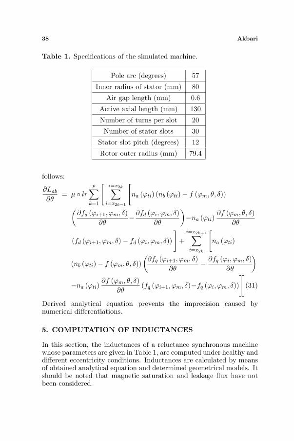
Table 1. Specifications of the simulated machine.
Pole arc (degrees) 57
Inner radius of stator (mm) 80
Air gap length (mm) 0.6
Active axial length (mm) 130
Number of turns per slot 20
Number of stator slots 30
Stator slot pitch (degrees) 12
Rotor outer radius (mm) 79.4
follows:
∂Lab
∂θ= µ ◦ lr
p∑
k=1
[i=x2k∑
i=x2k−1
[na (ϕti) (nb (ϕti)− f (ϕm, θ, δ))
(∂fd (ϕi+1, ϕm, δ)
∂θ− ∂fd (ϕi, ϕm, δ)
∂θ
)−na (ϕti)
∂f (ϕm, θ, δ)∂θ
(fd (ϕi+1, ϕm, δ)− fd (ϕi, ϕm, δ))
]+
i=x2k+1∑
i=x2k
[na (ϕti)
(nb (ϕti)− f (ϕm, θ, δ))(
∂fq (ϕi+1, ϕm, δ)∂θ
− ∂fq (ϕi, ϕm, δ)∂θ
)
−na (ϕti)∂f (ϕm, θ, δ)
∂θ(fq (ϕi+1, ϕm, δ)−fq (ϕi, ϕm, δ))
]](31)
Derived analytical equation prevents the imprecision caused bynumerical differentiations.
5. COMPUTATION OF INDUCTANCES
In this section, the inductances of a reluctance synchronous machinewhose parameters are given in Table 1, are computed under healthy anddifferent eccentricity conditions. Inductances are calculated by meansof obtained analytical equation and determined geometrical models. Itshould be noted that magnetic saturation and leakage flux have notbeen considered.

Progress In Electromagnetics Research M, Vol. 24, 2012 39
(a) (b)
Figure 6. (a) Calculated magnetizing inductance of stator phase Aand (b) mutual inductance between stator phase A and stator phaseB under different SE conditions.
(a) (b)
Figure 7. (a) Calculated magnetizing inductance of stator phase Aand (b) mutual inductance between stator phase A and stator phaseB under different DE conditions.
The profiles of magnetizing inductance of stator phase A andmutual inductance between phase A and B of stator under differenteccentricity conditions are shown in Figs. 6, 7 and 8. Comparison ofplots in these figures show how SE, DE and ME affect the profileof magnetizing and mutual inductances. ME causes asymmetricalmagnetizing and mutual inductances, whereas, DE and SE causesymmetrical inductances. In the cases of DE and SE, by increasing theeccentricity severity, the magnitude of these inductances increases. Therate of increase of the magnetizing inductance is higher than that of themutual inductance. Referring to Fig. 8 it is seen that the asymmetryoccurred in the magnetizing inductance in the case of ME is higherthan that of the mutual inductance.

40 Akbari
(a) (b)
Figure 8. (a) Calculated magnetizing inductance of stator phase Aand (b) mutual inductance between stator phase A and stator phaseB under different ME conditions.
Table 2. Specifications of a reluctance synchronous machine [19].
Pole arc/pole pitch 0.57Inner radius of stator (mm) 40.3
Air gap length (mm) 0.3Active axial length (mm) 75Number of turns per slot 58Number of stator slots 36
Stator slot pitch (degrees) 10Rotor outer radius(mm) 40
6. COMPARISON WITH FINITE ELEMENT RESULTS
In order to validate the proposed method, the inductances of areluctance synchronous machine whose parameters are given in theTable 2, is compared with FE results. A 2-D finite element analysiswas used to determine the inductances of stator windings [19]. Themagnetic saturation was neglected in order to match the windingfunction model which considers infinite permeability.
The plots of magnetizing inductance of stator phase A and mutualinductance between stator phase A and stator phase B obtained fromFE method and proposed method are shown in Figs. 9 and 10.
The results from the FE method, shown in Fig. 9, can be comparedwith those in Fig. 10, obtained by the proposed method. The smallripple which is present in the inductances profiles in Fig. 10 is dueto MMF variations across the slots. Minimum and maximum values

Progress In Electromagnetics Research M, Vol. 24, 2012 41
Table 3. Minimum and maximum values of inductances from twomethods (proposed method — FE method).
max-value (Henry) min-value (Henry)Lsaa 0.263–0.275 0.175–0.180Lsab 0.043–0.039 −0.21–−0.215
Figure 9. Self inductance of stator phase A (a) and mutual inductancebetween stator phase A and stator phase B (b) using FE method [19].
(a) (b)
Figure 10. (a) Calculated self inductance of stator phase A and (b)mutual inductance between stator phase A and stator phase B usingproposed technique.
of inductances from two methods are summarized in Table 3. Thecomparison indicates a good agreement between these two results.The main reason for good agreement between the proposed methodresults and the FE results is that in the proposed method, developmentin Fourier series of the inverse air gap function has not been used,but closed form equations are employed for inductances calculation.With this approach, all space harmonics ignored by the Fourier seriesexpansions of the inverse air gap function will be included in the model.The author plans to apply the calculated inductances in a coupledelectromagnetic model of reluctance synchronous machine in the futurefor fault analysis.

42 Akbari
7. CONCLUSION
In this paper, for calculation of reluctance synchronous machineinductances under different eccentricity conditions, a novel closed formanalytical expression is developed. For this purpose, the inverse air gapfunction of the eccentric reluctance machine has been defined and itsindefinite integral has then been determined. Derived comprehensiveequation allow calculating time varying inductances of reluctancemachines with different static, dynamic and mixed eccentricities inthe frame of a single program. The comparison between the proposedmethod and FEM results indicates a good agreement between thesetwo results. The main reason for good agreement is that in theproposed method, development in Fourier series of the inverse air gapfunction has not been used, but a closed form equation is employedfor inductances calculation. This leads to a very precise computationof the inductances of the faulted machine and more accurate results.Moreover, all space harmonics ignored by the Fourier series expansionsof the inverse air gap function will be included in the model. Thecalculated inductances can be applied in a coupled electromagneticmodel of reluctance synchronous machine for fault analysis.
ACKNOWLEDGMENT
This work was supported by Islamic Azad University, Yazd Branch,Yazd, Iran.
REFERENCES
1. Faiz, J. and B. M. Ebrahimi, “Mixed fault diagnosis in three-phasesquirrel-cage induction motor using analysis of air-gap magneticfield,” Progress In Electromagnetics Research, Vol. 64, 239–255,2006.
2. Faiz, J. and B. M. Ebrahimi, “Static eccentricity fault diagnosisin an accelerating no-load three-phase saturated squirrel-cageinduction motor,” Progress In Electromagnetics Research B,Vol. 10, 35–54, 2008.
3. Meshgin-Kelk, H., J. Milimonfared, and H. Toliyat, “Interbarcurrents and axial fluxes in healthy and faulty induction motors,”IEEE Transactions on Industry Applications, Vol. 40, No. 1, 128–134, 2004
4. Faiz, J., B. M. Ebrahimi, and M. B. B. Sharifian, “Differentfaults and their diagnosis techniques in three-phase squirrel-cage

Progress In Electromagnetics Research M, Vol. 24, 2012 43
induction motors — A review,” Electromagnetics, Vol. 26, No. 7,543–569, 2006.
5. Faiz, J., B. M. Ebrahimi, and M. B. B. Sharifian, “Time steppingfinite element analysis of rotor broken bars fault in a three-phasesquirrel-cage induction motor,” Progress In ElectromagneticsResearch, Vol. 68, 53–70, 2007.
6. Torkaman, H. and E. Afjei, “FEM analysis of angularmisalignment fault in SRM magnetostatic characteristics,”Progress In Electromagnetics Research, Vol. 104, 31–48, 2010.
7. Vaseghi, B., N. Takorabet, and F. Meibody-Tabar, “Transientfinite element analysis of induction machines with stator windingturn fault,” Progress In Electromagnetics Research, Vol. 95, 118,2009
8. Torkaman, H. and E. Afjei, “Hybrid method of obtaining degreesof freedom for radial air gap length in SRM under normal andfaulty conditions based on magnetostatic model,” Progress InElectromagnetics Research, Vol. 100, 3754, 2010.
9. De Bortoli, M. J., S. J. Salon, and C. J. Slavic, “Effect of rotoreccentricity and parallel winding on induction behavior: A studyusing finite element analysis,” IEEE Transactions on Magnetics,Vol. 29, No. 2, 1676–1682, 1993.
10. Toliyat, H., T. A. Lipo, and J. C. White, “Analysis of aconcentrated winding induction machine for adjustable speeddrive applications, part-1 (motor analysis),” IEEE Transactionson Energy Conversion, Vol. 6, 679–692, 1991.
11. Milimonfared, J., H. M. Kelk, A. Der Minassians, S. Nandi, andH. A. Toliyat, “A novel approach for broken bar detection in cageinduction motors,” IEEE Transactions on Industry Applications,Vol. 35, 1000–1006, 1999.
12. Joksimovic, M. G. and J. Penman, “The detection of inter turnshort circuits in the stator windings of operating motors,” IEEETransactions on Industry Application, Vol. 47, 1078–1084, 2000.
13. Al-Nuaim, N. A. and H. Toliyat, “A novel method for modelingdynamic air-gap eccentricity in synchronous machines based onmodified winding function theory,” IEEE Transactions on EnergyConversion, Vol. 13, 156–162, 1998.
14. Tabatabaei, I., J. Faiz, H. Lesani, and M. T. Nabavi-Razavi,“Modeling and simulation of a salient pole synchronous generatorwith dynamic eccentricity using modified winding functionapproach,” IEEE Transactions on Magnetics, Vol. 40, No. 3,May 2004.

44 Akbari
15. Joksimovic, G. M., “Dynamic simulation of cage inductionmachine with air gap eccentricity,” IEE Proc. Electr. Power Appl.,Vol. 152, No. 4, 803–811, Jul. 2005.
16. Faiz, J., B. M. Ebrahimi, and M. Valavi, “Mixed eccentricity faultdiagnosis in salient pole synchronous generator using modifiedwinding function method,” Progress In Electromagnetics ResearchB, Vol. 11, 155–172, 2009.
17. Akbari, H., J. Milimonfared, and H. Meshgin Kelk, “Axialstatic eccentricity detection in induction machines by wavelettechnique,” International Review of Electrical Engineering, Vol. 5,No. 3, 2010.
18. Akbari, H., H. Meshgin Kelk, and J. Milimonfared, “Extension ofwinding function theory for radial and axial non-uniform air gap insalient pole synchronous machines,” Progress In ElectromagneticsResearch, Vol. 114, 407428, 2011.
19. Lubin, T. and T. Hamiti, “Comparison between finite-elementanalysis and winding function theory for inductances andtorque calculation of a synchronous reluctance machine,” IEEETransactions on Magnetics, Vol. 43, No. 8, 2007.
20. Neti, P. and S. Nandi, “Performance analysis of a reluctancesynchronous motor under abnormal operating conditions,” Can.J. Elec. Comput. Eng., Vol. 33, No. 2, 2008.
21. Hamiti, T., T. Lubin, and A. Rezzoug, “A simple and efficienttool for design analysis of synchronous reluctance motor,” IEEETransactions on Magnetics, Vol. 44, No. 12, Dec. 2008.
22. Obe, E. S., “Direct computation of AC machine inductancesbased on winding function theory,” Energy Conversion andManagement, Vol. 50, 539–542, 2009.
23. Hamiti, T., T. Lubin, L. Baghli, and A. Rezzoug, “Modeling of asynchronous reluctance machine accounting for space harmonics inview of torque ripple minimization,” Mathematics and Computersin Simulation, Vol. 81, 354–366, 2010.
24. Akbari, H., J. Milimonfared, and H. Meshgin Kelk, “ImprovedMWFA for computation of salient pole machine inductances,”International Review of Electrical Engineering, Vol. 5, No. 6,2593–2600, 2010.
25. Ostovic, V., Computer Aided Analysis of Electrical Machines, AMathematical Approach, Prentice Hall, 1994.


![TraceMatch: a Computer Vision Technique for User Input by … · 2017-06-26 · direct touch input on interactive surfaces [17], or employ syn-chronous gestures to define continuous](https://static.fdocuments.in/doc/165x107/5ea47ac18d21261e8565a2e2/tracematch-a-computer-vision-technique-for-user-input-by-2017-06-26-direct-touch.jpg)


![arXiv:2004.06095v1 [physics.atom-ph] 13 Apr 2020 · state of the art [25, 26], yielding a relative fractional frequency stability of 5.2(3) 10 17 (˝=s) 1=2 for syn-chronous self-comparisons.](https://static.fdocuments.in/doc/165x107/5f79cc5103f804582a549e14/arxiv200406095v1-13-apr-2020-state-of-the-art-25-26-yielding-a-relative.jpg)
