Analysis,SimulationsandImprovement...
35
Analysis, Simulations and Improvement Proposals of IEEE 802.15.4g-2012 Master’s thesis in Communication Engineering LIANG XUE Department of Signals and Systems Chalmers University of Technology Gothenburg, Sweden 2015
Transcript of Analysis,SimulationsandImprovement...
Analysis, Simulations and ImprovementProposals of IEEE 802.15.4g-2012Master’s thesis in Communication Engineering
LIANG XUE
Department of Signals and SystemsChalmers University of TechnologyGothenburg, Sweden 2015

Master’s thesis 2015:NN
Analysis, Simulations and Improvement Proposalsof IEEE 802.15.4g-2012
LIANG XUE
Department of Signals and SystemsChalmers University of Technology
Gothenburg, Sweden 2015
Analysis, Simulations and Improvement Proposals of IEEE 802.15.4g-2012LIANG XUE
© LIANG XUE, 2015.
Supervisor: Tomas Lennvall, Mikael Gidlund, ABB CRCExaminer: Henk Wymeersch, Department of Signals and Systems
Master’s Thesis 2015:NNDepartment of Signals and SystemsChalmers University of TechnologySE-412 96 GothenburgTelephone +46 31 772 1000
Typeset in LATEXGothenburg, Sweden 2015
iv
Analysis, Simulations and Improvement Proposals of IEEE 802.15.4g-2012LIANG XUEDepartment of Signals and SystemsChalmers University of Technology
AbstractIEEE 802.15.4g-2012 is a new amendment of the communication standard IEEE802.15.4-2011. IEEE 802.15.4g-2012 enables multiple applications to operate in thesame location and share the same frequency band.In this thesis we analyze the MAC layers and PHYs of both standards and discussabout the major differences between them. Then we show the simulation results ofIEEE 802.15.4-2011 O-QPSK PHY and IEEE 802.15.4g-2012 MR-O-QPSK PHY,where the simulation performance is measured with the BER.By analyzing the simulation results we draw the conclusion that in AWGN channelwithout burst errors or unpredicted inverse of the bit streams, IEEE 802.15.4-2011O-QPSK PHY performs better than IEEE 802.15.4g-2012 MR-O-QPSK PHY whenthe data rate keeps the same.We propose a spreading map switching mechanism that may improve the perfor-mance of the IEEE 802.15.4-2011 O-QPSK PHY in different application scenarios.We also propose a dynamic mode switching mechanism to choose the optimal PHYmode in different application scenarios to make better use of the MR-PHYs in IEEE802.15.4g-2012.
Keywords: IEEE 802.15.4-2011, IEEE 802.15.4g-2012, MAC, PHY, O-QPSK, AWGN
v

Contents
1 Introduction 11.1 Purpose . . . . . . . . . . . . . . . . . . . . . . . . . . . . . . . . . . 11.2 Outline . . . . . . . . . . . . . . . . . . . . . . . . . . . . . . . . . . . 1
2 Analysis of IEEE 802.15.4-2011 32.1 General description . . . . . . . . . . . . . . . . . . . . . . . . . . . . 32.2 Devices and topologies . . . . . . . . . . . . . . . . . . . . . . . . . . 32.3 MAC layer functions . . . . . . . . . . . . . . . . . . . . . . . . . . . 32.4 PHY descriptions . . . . . . . . . . . . . . . . . . . . . . . . . . . . . 6
3 Analysis of IEEE 802.15.4g-2012 93.1 Differences in MAC layers . . . . . . . . . . . . . . . . . . . . . . . . 9
3.1.1 MPM procedure . . . . . . . . . . . . . . . . . . . . . . . . . . 93.1.2 Enhanced beacon . . . . . . . . . . . . . . . . . . . . . . . . . 103.1.3 Information element . . . . . . . . . . . . . . . . . . . . . . . 103.1.4 FCS fields . . . . . . . . . . . . . . . . . . . . . . . . . . . . . 113.1.5 Channel pages . . . . . . . . . . . . . . . . . . . . . . . . . . . 113.1.6 Packet size and PER tolerance . . . . . . . . . . . . . . . . . . 11
3.2 SUN PHYs descriptions . . . . . . . . . . . . . . . . . . . . . . . . . . 123.2.1 MR-FSK . . . . . . . . . . . . . . . . . . . . . . . . . . . . . . 12
3.2.1.1 Description . . . . . . . . . . . . . . . . . . . . . . . 123.2.1.2 PPDU format . . . . . . . . . . . . . . . . . . . . . . 123.2.1.3 Mode switch mechanism . . . . . . . . . . . . . . . . 12
3.2.2 MR-OFDM . . . . . . . . . . . . . . . . . . . . . . . . . . . . 123.2.2.1 Description . . . . . . . . . . . . . . . . . . . . . . . 123.2.2.2 Frame format . . . . . . . . . . . . . . . . . . . . . . 123.2.2.3 Bit-to-symbol mapping . . . . . . . . . . . . . . . . . 133.2.2.4 FEC . . . . . . . . . . . . . . . . . . . . . . . . . . . 13
3.2.3 MR-O-QPSK . . . . . . . . . . . . . . . . . . . . . . . . . . . 133.2.3.1 Description . . . . . . . . . . . . . . . . . . . . . . . 133.2.3.2 PPDU format . . . . . . . . . . . . . . . . . . . . . . 133.2.3.3 FEC . . . . . . . . . . . . . . . . . . . . . . . . . . . 133.2.3.4 Interleaving . . . . . . . . . . . . . . . . . . . . . . . 133.2.3.5 BDE . . . . . . . . . . . . . . . . . . . . . . . . . . . 143.2.3.6 Processing diagrams . . . . . . . . . . . . . . . . . . 14
vii
Contents
4 Simulations 154.1 Simulation process of IEEE 802.15.4-2011 O-QPSK PHY . . . . . . . 154.2 Simulation process of IEEE 802.15.4g-2012 MR-O-QPSK PHY . . . . 16
4.2.1 MR-O-QPSK (16,4)-DSSS . . . . . . . . . . . . . . . . . . . . 164.2.2 MR-O-QPSK (32,1)-DSSS . . . . . . . . . . . . . . . . . . . . 17
4.3 Simulation results . . . . . . . . . . . . . . . . . . . . . . . . . . . . . 18
5 Improvement Proposals 215.1 Improvement proposal for IEEE 802.15.4-2011 . . . . . . . . . . . . . 215.2 Improvement proposal for IEEE 802.15.4g-2012 . . . . . . . . . . . . 21
6 Conclusions 25
viii
1Introduction
1.1 PurposeIn industrial applications it takes a lot of resources to implement a new commu-nication standard so it is important to test if this new standard is worthy enoughto be implemented. The purpose of this thesis is to gather information to analyzeIEEE 802.15.4g-2012 and test the performance of IEEE 802.15.4g-2012 multi-rateand multi-regional offset quadrature phase-shift keying (MR-O-QPSK) Port Physi-cal Layer (PHY) compared with IEEE 802.15.4-2011 O-QPSK PHY. After analyzingthe standards documents and the simulation results we propose two mechanisms toimprove the performance of IEEE 802.15.4-2011 O-QPSK PHY and IEEE 802.15.4g-2012 PHYs.
1.2 Outline• In chapter 1, we explain the purpose and the outline of this thesis.• In chapter 2, we analyze the Media Access Control (MAC) layer and PHYs of
IEEE 802.15.4-2011. We focus on MAC functions and O-QPSK PHY in thischapter.
• In chapter 3, we discuss the major differences between IEEE 802.15.4g-2012and IEEE 802.15.4-2011 in MAC layer. Then we analyze the three PHYs ofIEEE 802.15.4g-2012 while MR-O-QPSK is mainly discussed.
• In chapter 4, we present the mathematical description of the simulation pro-cedures of IEEE 802.15.4-2011 O-QPSK PHY and IEEE 802.15.4g-2012 MR-O-QPSK PHY. We take the 2450MHz band which is world-widely used inindustry [1] as the frequency band in simulations. The BER performance isdisplayed according to the simulation results.
• In chapter 5, based on the analysis and simulation results, we propose a spread-ing map switching mechanism for IEEE 802.15.4-2011 O-QPSK PHY and adynamic mode switching mechanism for IEEE 802.15.4g-2012 PHYs to makeimprovements.
• In chapter 6, we draw our conclusions.
1

1. Introduction
2
2Analysis of IEEE 802.15.4-2011
2.1 General descriptionIEEE 802.15.4-2011 is a communication standard defined by IEEE 802.15 workinggroup in 2003. IEEE 802.15.4-2011 is the basis of some upper applications suchas the ZigBee, WirelessHART and MiWi. [2] It specifies the physical layer andMAC for LR-WPANs (low-rate wireless personal area networks). An LR-WPAN isan energy-efficient communication network. LR-WPAN provides easy installation,reliable data transmission and low energy cost, which make it suitable for wirelesscommunications in limited-energy applications. In this paper the IEEE 802.15.4-2011(hereinafter referred to as IEEE 802.15.4-2011), which was released in 2011, ismainly discussed.
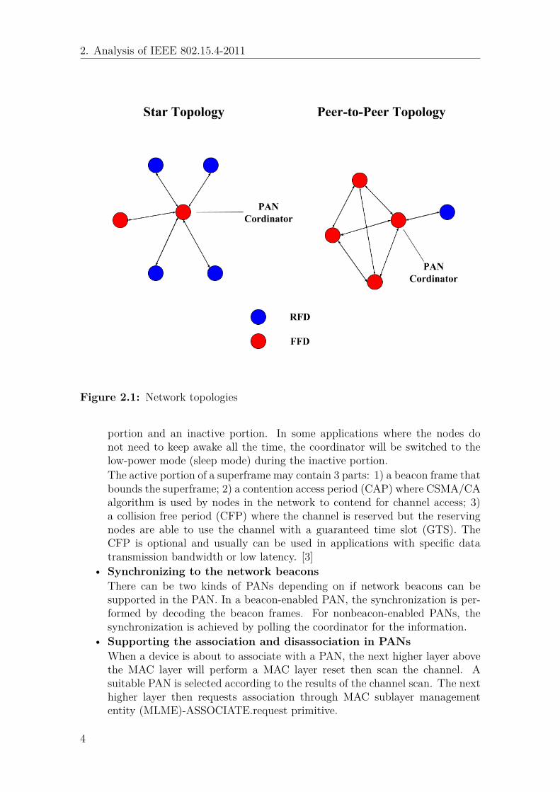
2.2 Devices and topologiesTwo kinds of devices can be implemented in an IEEE 802.15.4-2011 network. A full-function device(FFD) is a device that can operate as a personal area network (PAN)coordinator or a normal network coordinator. The other one is the reduced-functiondevice(RFD) which can not serve as a coordinator. An RFD can only associate withone FFD at a time and is usually used to send small amount of data. The RFDsare mainly implemented in simple applications.There are two typical network topologies implemented in IEEE 802.15.4-2011 LR-WPANs: the star topology and the peer-to-peer topology, as shown in Figure 2.1. Ina star topology a PAN coordinator, which serves as a central controller, is in chargeof the initiation, termination or route communications of the network. In a peer-to-peer topology, each device is able to communicate to all its neighbor devices. Thepeer-to-peer topology can be used in some complex applications, such as wirelesssensor networks and industrial control.
2.3 MAC layer functionsThe media access control (MAC) sublayer in IEEE 802.15.4-2011 is responsible forthe following tasks:
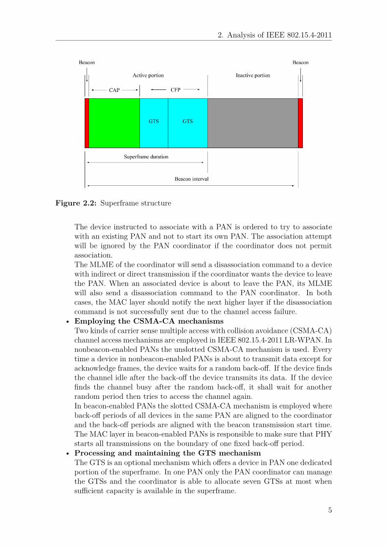
• Generating the network beacons for the PAN coordinatorsA superframe structure can be used by a coordinator in a PAN to bound thechannel time. As depicted in Figure 2.2, a superframe may contain an active
3
2. Analysis of IEEE 802.15.4-2011
Figure 2.1: Network topologies
portion and an inactive portion. In some applications where the nodes donot need to keep awake all the time, the coordinator will be switched to thelow-power mode (sleep mode) during the inactive portion.The active portion of a superframe may contain 3 parts: 1) a beacon frame thatbounds the superframe; 2) a contention access period (CAP) where CSMA/CAalgorithm is used by nodes in the network to contend for channel access; 3)a collision free period (CFP) where the channel is reserved but the reservingnodes are able to use the channel with a guaranteed time slot (GTS). TheCFP is optional and usually can be used in applications with specific datatransmission bandwidth or low latency. [3]
• Synchronizing to the network beaconsThere can be two kinds of PANs depending on if network beacons can besupported in the PAN. In a beacon-enabled PAN, the synchronization is per-formed by decoding the beacon frames. For nonbeacon-enabled PANs, thesynchronization is achieved by polling the coordinator for the information.
• Supporting the association and disassociation in PANsWhen a device is about to associate with a PAN, the next higher layer abovethe MAC layer will perform a MAC layer reset then scan the channel. Asuitable PAN is selected according to the results of the channel scan. The nexthigher layer then requests association through MAC sublayer managemententity (MLME)-ASSOCIATE.request primitive.
4
2. Analysis of IEEE 802.15.4-2011
Figure 2.2: Superframe structure
The device instructed to associate with a PAN is ordered to try to associatewith an existing PAN and not to start its own PAN. The association attemptwill be ignored by the PAN coordinator if the coordinator does not permitassociation.The MLME of the coordinator will send a disassociation command to a devicewith indirect or direct transmission if the coordinator wants the device to leavethe PAN. When an associated device is about to leave the PAN, its MLMEwill also send a disassociation command to the PAN coordinator. In bothcases, the MAC layer should notify the next higher layer if the disassociationcommand is not successfully sent due to the channel access failure.
• Employing the CSMA-CA mechanismsTwo kinds of carrier sense multiple access with collision avoidance (CSMA-CA)channel access mechanisms are employed in IEEE 802.15.4-2011 LR-WPAN. Innonbeacon-enabled PANs the unslotted CSMA-CA mechanism is used. Everytime a device in nonbeacon-enabled PANs is about to transmit data except foracknowledge frames, the device waits for a random back-off. If the device findsthe channel idle after the back-off the device transmits its data. If the devicefinds the channel busy after the random back-off, it shall wait for anotherrandom period then tries to access the channel again.In beacon-enabled PANs the slotted CSMA-CA mechanism is employed whereback-off periods of all devices in the same PAN are aligned to the coordinatorand the back-off periods are aligned with the beacon transmission start time.The MAC layer in beacon-enabled PANs is responsible to make sure that PHYstarts all transmissions on the boundary of one fixed back-off period.
• Processing and maintaining the GTS mechanismThe GTS is an optional mechanism which offers a device in PAN one dedicatedportion of the superframe. In one PAN only the PAN coordinator can managethe GTSs and the coordinator is able to allocate seven GTSs at most whensufficient capacity is available in the superframe.
5
2. Analysis of IEEE 802.15.4-2011
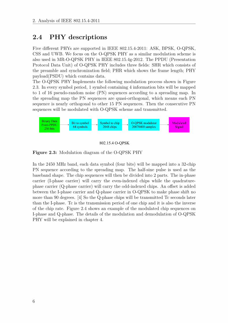
2.4 PHY descriptionsFive different PHYs are supported in IEEE 802.15.4-2011: ASK, BPSK, O-QPSK,CSS and UWB. We focus on the O-QPSK PHY as a similar modulation scheme isalso used in MR-O-QPSK PHY in IEEE 802.15.4g-2012. The PPDU (PresentationProtocol Data Unit) of O-QPSK PHY includes three fields: SHR which consists ofthe preamble and synchronization field; PHR which shows the frame length; PHYpayload(PSDU) which contains data.The O-QPSK PHY Implements the following modulation process shown in Figure2.3. In every symbol period, 1 symbol containing 4 information bits will be mappedto 1 of 16 pseudo-random noise (PN) sequences according to a spreading map. Inthe spreading map the PN sequences are quasi-orthogonal, which means each PNsequence is nearly orthogonal to other 15 PN sequences. Then the consecutive PNsequences will be modulated with O-QPSK scheme and transmitted.
Figure 2.3: Modulation diagram of the O-QPSK PHY
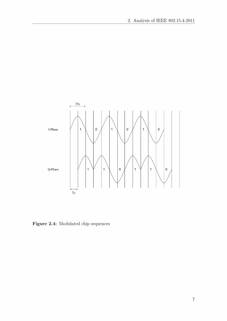
In the 2450 MHz band, each data symbol (four bits) will be mapped into a 32-chipPN sequence according to the spreading map. The half-sine pulse is used as thebaseband shape. The chip sequences will then be divided into 2 parts. The in-phasecarrier (I-phase carrier) will carry the even-indexed chips while the quadrature-phase carrier (Q-phase carrier) will carry the odd-indexed chips. An offset is addedbetween the I-phase carrier and Q-phase carrier in O-QPSK to make phase shift nomore than 90 degrees. [4] So the Q-phase chips will be transmitted Tc seconds laterthan the I-phase. Tc is the transmission period of one chip and it is also the inverseof the chip rate. Figure 2.4 shows an example of the modulated chip sequences onI-phase and Q-phase. The details of the modulation and demodulation of O-QPSKPHY will be explained in chapter 4.
6
2. Analysis of IEEE 802.15.4-2011
Figure 2.4: Modulated chip sequences
7

2. Analysis of IEEE 802.15.4-2011
8
3Analysis of IEEE 802.15.4g-2012
As an amendment of the IEEE 802.15.4-2011, IEEE 802.15.4g-2012 implementsthe smart utility networks (SUNs) which enables multiple applications to work withshared network resources and provides control of a utility system. [5] These networksare usually large and diverse, with a big number of outdoor devices inside. Sonew management methods and functional blocks are introduced to MAC layers andPHYs in IEEE 802.15.4g-2012g. We will discuss about the differences between IEEE802.15.4g-2012 and IEEE-802.15.4-2011 in this chapter.
3.1 Differences in MAC layers
In this section we analyze the MAC layer of IEEE 802.15.4g-2012 by discuss thedifferences between its MAC layer and the MAC layer of IEEE 802.15.4-2011.
3.1.1 MPM procedureThree alternative PHYs are provided in IEEE 802.15.4g-2012 for the SUN devicesto support the applications in different conditions:
• MR-FSKMulti-rate and multi-regional frequency shift keying (MR-FSK) PHY providesremarkable transmission power efficiency because of the constant envelope ofthe signal.
• MR-OFDMMulti-rate and multi-regional orthogonal frequency division multiplexing (MR-OFDM) PHY provides the high data rates as well as high spectral efficiency.
• MR-O-QPSKMulti-rate and multi-regional offset quadrature phase-shift keying (MR-O-QPSK) PHY results in less cost in the multi-mode systems and makes thesystem easier to design. It is the PHY mode on which we focus in this thesis.
The IEEE 802.15.4g-2012 aims to make it possible that multiple, different SUNPHYs can operate in the same location and in the same frequency band. In order tomitigate the interference among different PHYs a multi-PHY management scheme(MPM) is specified for SUNs. The MPM scheme is introduced to facilitate theinteroperability and negotiation among potential PAN coordinators working withdifferent PHYs. In this process the MPM shall permit a coordinator to detect anexisting working network during its discovery phase, using the common signaling
9
3. Analysis of IEEE 802.15.4g-2012
mode (CSM). The CSM discussed here is a common physical layer mode used be-tween SUN devices implementing MPM scheme.
3.1.2 Enhanced beaconThe enhanced beacon (EB) is a newMAC frame that is introduced in IEEE 802.15.4g-2012 to support the work of the MPM procedure. In a beacon-enabled PAN, unlikethe usual periodic beacon which is located in front of the CAP, the enhanced beaconis designed to be transmitted at a fixed interval in CAP and can only be sent inCAP. [5]The transmission of EBs should be processed in all the channels that are defined forCSM and overlap with other channels in operation. Also, the scanning for EBs andthe transmission of the enhanced beacon requests (EBRs) should be processed inall the channels that are defined for CSM and overlap with the channel of interest.There can be several different schemes for the transmissions and scanning of theEBs in beacon-enabled PANs and nonbeacon-enabled PANs:
• In a beacon-enabled PAN, a coordinator which is currently operating a net-work shall always transmit an EB at a fixed interval using CSM. If anothercoordinator is intending to start a separate network, it shall scan for an EBuntil the expiration of the enhanced beacon interval (EBI) or till an EB isdetected. When an EB is detected by the intending coordinator, the intend-ing coordinator shall take the methods depending on the specific conditions.These methods are:1. The intending coordinator could try to occupy another available channel.2. The intending coordinator could try to achieve synchronization with the
existing PAN which is operating a network. The timing information ap-plicable for synchronization purposes will be specified in the EB whilespecific mechanisms to achieve synchronization between two PANs utiliz-ing different PHY modes are implementation-dependent.
3. The intending coordinator could just stop communication and wait foranother chance.
• In a nonbeacon-enabled PAN, the same scheme discussed above can be usedfor transmitting and scanning the EBs as in beacon-enabled PAN. Optionally,an EB can be obtained in an on-demand way where an EBR containing theID, which is in the list of IE IDs, will be sent by the intending coordinatorto demand an EB from the existing working coordinator. And the existingcoordinator will send an EB to the intending coordinator as a response whenreceiving the EBR. The intending coordinator should transmit at least oneEBR in every EBI, while the existing coordinator should periodically scan forthe EBR in CSM to increase the probability of detecting the EBR.
3.1.3 Information elementThe information element (IE) is a new field which is introduced to the IEEE802.15.4g-2012 MAC frames for the implementations of different functions. Thereare four types of IE in IEEE 802.15.4g-2012:
10
3. Analysis of IEEE 802.15.4g-2012
• Coexistence specification IE is used to convey the parameters that define theEB. This kind of IE is included in the enhanced beacon frame to indicate theimportant information of EBs such as beacon order, enhanced beacon order,channel page, etc. The length of coexistence specification IE is 9 octets.
• SUN PHY capability IE is used to declare the PHY capabilities of the SUNdevice.
• MR-FSK generic PHY descriptor IE is used to declare one MR-FSK genericPHY descriptor.
• Mode switch parameter entry IE is defined to declare one mode switch param-eter entry.
3.1.4 FCS fields
Due to the longer payload of the IEEE 802.15.4g-2012 MAC frame, the frame checksequence (FCS) field contains a 32-bit cyclic redundancy check (CRC) while inIEEE-802.15.4-2011 the FCS field usually contains a 16-bit ITU-T CRC. Devicesoperating with one or more of the SUN PHYs shall implement the 4-octets FCS andthe default FCS length for these devices is 4 octets.
3.1.5 Channel pages
A greater channel numbering capability is required due to the addition of the SUNPHY specifications. The definitions of the channel pages nine and ten have beenmodified for the SUN PHYs to provide the larger number of channels. The existingchannel assignment schemes are still maintained at the same time. Channel pagenine specifies each standard-defined SUN PHY operating mode supported by thedevice. These specifications are frequency band(s), modulation scheme(s) and PHYmode(s). Channel page ten defines the specifications of the MR-FSK Generic-PHY-defined PHY modes.
3.1.6 Packet size and PER tolerance
The receiver sensitivity is defined as the lowest input power for which the packeterror rate (PER) conditions are met. To meet the PER conditions the PSDU lengthshould be more than 250 octets for SUN PHYs with data rates 50 kb/s and greaterwhile the PSDU length should be more than 20 octets for all other PHYs. The PERshould be less than 10% for SUN PHYs while the PER should be less than 1% forthe other PHYs. [5] These specifications indicate that the packet size for SUN PHYsis over ten times larger than other PHYs and the PER that can be tolerated in SUNPHYs is much higher than it is in other PHYs.
11
3. Analysis of IEEE 802.15.4g-2012
3.2 SUN PHYs descriptions
3.2.1 MR-FSK
3.2.1.1 Description
Frequency-shift keying (FSK) is a digital modulation scheme which is commonlyused in high-frequency communication spectrum. [6] In FSK, the information iscarried by the frequency changes of the carrier waves. In IEEE 802.15.4g-2012different data transmission rates can be supported by the MR-FSK PHY.
3.2.1.2 PPDU format
The MR-FSK PPDU includes the synchronization header (SHR), PHY header (PHR),and PHY payload. These components are treated as bit strings of length n, num-bered b0 on the left and bn−1 on the right. When transmitted, they are processed b0first to bn−1 last, without regard to their content or structure.
3.2.1.3 Mode switch mechanism
The most impressive feature about the MR-FSK is the mode switch mechanism.This mechanism enables the a device using MR-FSK PHY to change its symbol rateand/or modulation scheme on a packet-by-packet basis (i.e. different modes couldbe applied in different single packets).An MR-FSK mode switch PPDU will be transmitted on phyCurrentChannel by thedevice which has changed its PHY mode. When this PPDU is received by anotherdevice which supports the mode switching, the device shall change its operationmode to the new mode defined in the PPDU in order to receive the coming packets.There will be a setting delay when changing the current operating mode to a newmode. The delay depends on the specific mode switch types.With the mode switch mechanism the nodes in wireless sensor networks are able tochange the symbol rates and modulation schemes according to the environment andneeds. Also, this mechanism permits two devices using FSK PHY to establish thecommunication in a different PHY mode.
3.2.2 MR-OFDM
3.2.2.1 Description
In IEEE 802.15.4g-2012 the MR-OFDM PHY provides the high data rates, rangingfrom 50kb/s to 800kb/s. The signal bandwidth ranges from 1.2 MHz to less than200 kHz.
3.2.2.2 Frame format
The frame of the MR-OFDM includes SHR, PHR and payload fields. The SHR fieldconsists of short training field (STF) and long training field (LTF).
12
3. Analysis of IEEE 802.15.4g-2012
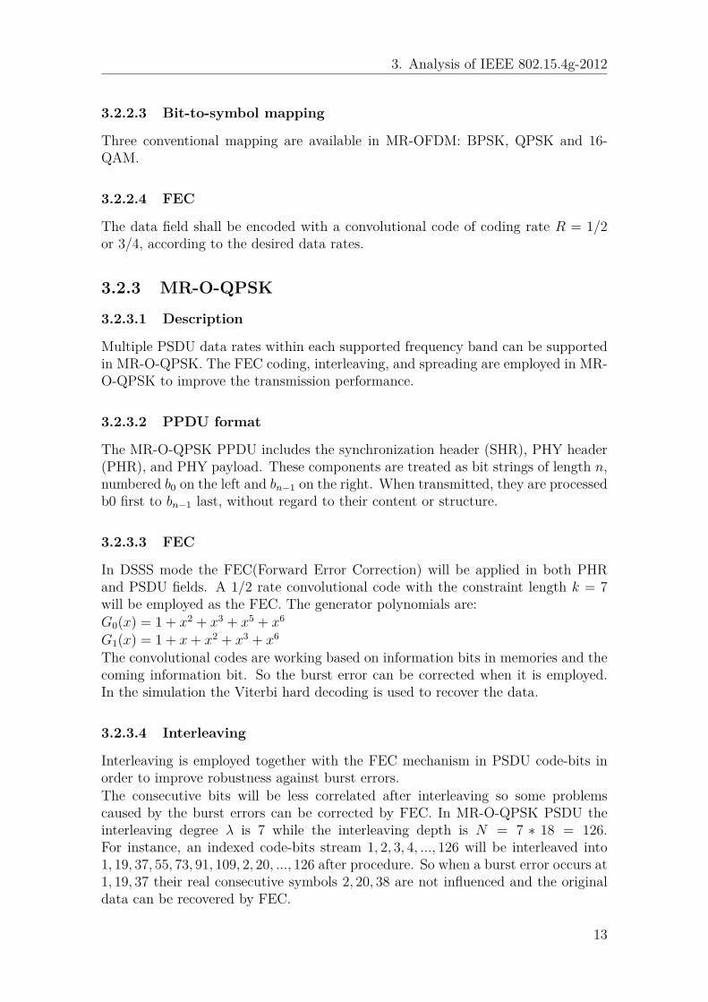
3.2.2.3 Bit-to-symbol mapping
Three conventional mapping are available in MR-OFDM: BPSK, QPSK and 16-QAM.
3.2.2.4 FEC
The data field shall be encoded with a convolutional code of coding rate R = 1/2or 3/4, according to the desired data rates.
3.2.3 MR-O-QPSK
3.2.3.1 Description
Multiple PSDU data rates within each supported frequency band can be supportedin MR-O-QPSK. The FEC coding, interleaving, and spreading are employed in MR-O-QPSK to improve the transmission performance.
3.2.3.2 PPDU format
The MR-O-QPSK PPDU includes the synchronization header (SHR), PHY header(PHR), and PHY payload. These components are treated as bit strings of length n,numbered b0 on the left and bn−1 on the right. When transmitted, they are processedb0 first to bn−1 last, without regard to their content or structure.
3.2.3.3 FEC
In DSSS mode the FEC(Forward Error Correction) will be applied in both PHRand PSDU fields. A 1/2 rate convolutional code with the constraint length k = 7will be employed as the FEC. The generator polynomials are:G0(x) = 1 + x2 + x3 + x5 + x6
G1(x) = 1 + x+ x2 + x3 + x6
The convolutional codes are working based on information bits in memories and thecoming information bit. So the burst error can be corrected when it is employed.In the simulation the Viterbi hard decoding is used to recover the data.
3.2.3.4 Interleaving
Interleaving is employed together with the FEC mechanism in PSDU code-bits inorder to improve robustness against burst errors.The consecutive bits will be less correlated after interleaving so some problemscaused by the burst errors can be corrected by FEC. In MR-O-QPSK PSDU theinterleaving degree λ is 7 while the interleaving depth is N = 7 ∗ 18 = 126.For instance, an indexed code-bits stream 1, 2, 3, 4, ..., 126 will be interleaved into1, 19, 37, 55, 73, 91, 109, 2, 20, ..., 126 after procedure. So when a burst error occurs at1, 19, 37 their real consecutive symbols 2, 20, 38 are not influenced and the originaldata can be recovered by FEC.
13
3. Analysis of IEEE 802.15.4g-2012
3.2.3.5 BDE
The Bit Differential Encoding (BDE) is employed to correct the errors caused bythe unpredicted inverse of the bit streams when data is transmitted through thecommunication channels in reality. This encoding can be simply described by anequation:En = Rn ⊕ En−1So even if the coded bit streams became inverted (0 turned into 1 or 1 turned into0) the differences between consecutive bits stay the same. So the information isprotected by introducing BDE.
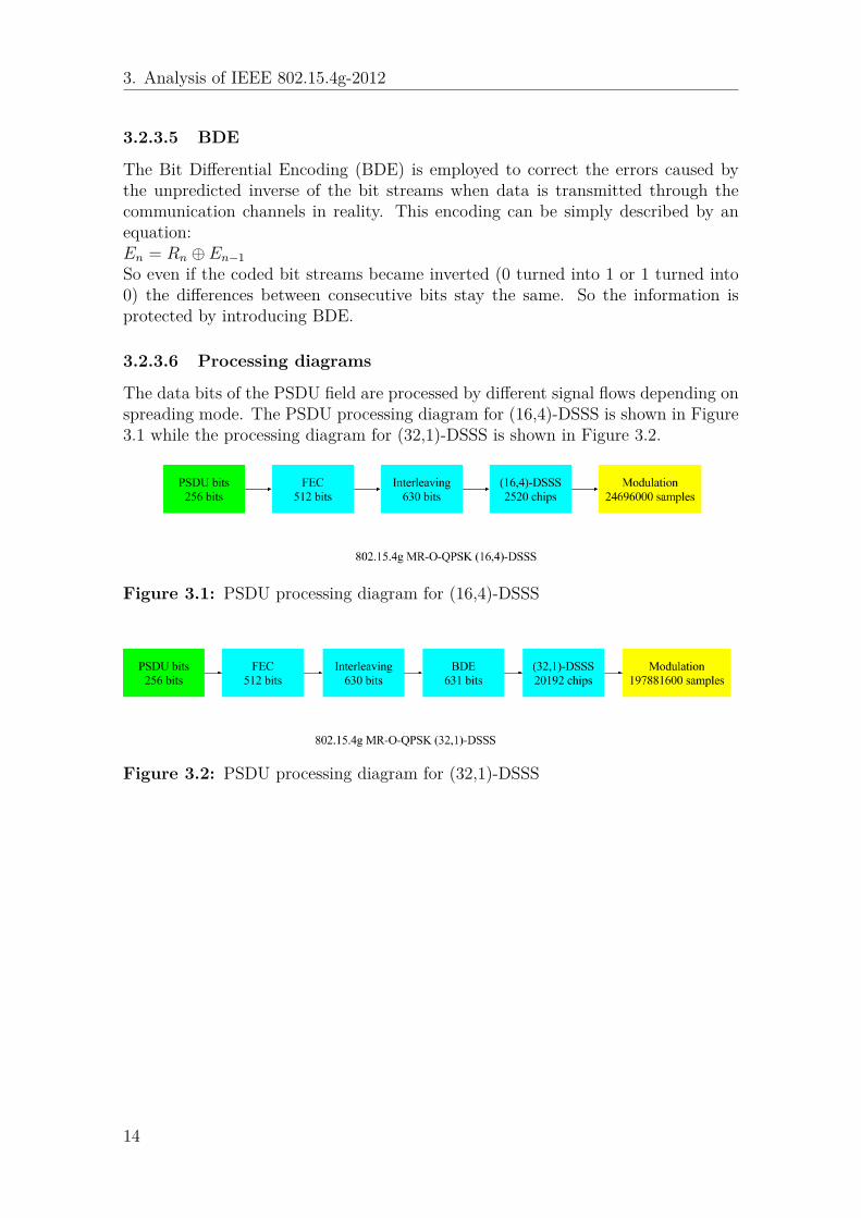
3.2.3.6 Processing diagrams
The data bits of the PSDU field are processed by different signal flows depending onspreading mode. The PSDU processing diagram for (16,4)-DSSS is shown in Figure3.1 while the processing diagram for (32,1)-DSSS is shown in Figure 3.2.
Figure 3.1: PSDU processing diagram for (16,4)-DSSS
Figure 3.2: PSDU processing diagram for (32,1)-DSSS
14
4Simulations
4.1 Simulation process of IEEE 802.15.4-2011 O-QPSK PHY
We run the simulation of IEEE 802.15.4-2011 O-QPSK PHY with a 256-bit originalpacket by taking following steps:
1. Symbols = f1(Packet data);Chip sequences = f2(Symbols)Here f1 is a function that converts every 4 bits to a hexadecimal symbol. f2is a function that maps each symbol to a 32 chips.
2. Symbol rate = Data rate/4;Chip rate = Symbol rate ∗ 32;3. Number of samples = Ns = 2 ∗ S ∗ Fc/Rc = 16 ∗ Fc/Rc
Fc is the carrier frequency which is 2450 MHz here and Rc is the chip rate.S is the sampling factor which is 8 in the simulations. So Ns is the numberof samples in each chip on the I-phase or Q-phase. Let Nc be the number ofchips and V (n) be the value of each chip, n = 0, 1, 2, ..., Nc − 1.Discrete samples in each chip on the I-phase and Q-phase carriers can beexplained as follows.
4. SampleI(t, n) =√
(2) ∗ sin(π ∗ t/Ns) ∗ cos(2 ∗ π ∗ t/8) ∗ V (n),t = 1, 2, 3, ..., Nc ∗Ns/2;n = 0, 2, 4, ..., Nc − 2.SampleQ(t, n) = 0, t <= Ns/2.SampleQ(t, n) =
√(2)∗sin(π∗(t−Ns/2)/Ns)∗sin(2∗π∗(t−Ns/2)/8)∗V (n),
t = Ns/2 + 1, Ns/2 + 2, Ns/2 + 3, ..., Nc ∗Ns/2;n = 1, 3, 5, ..., Nc − 15. Modulated signal = S(t) = SampleI(t) + SampleQ(t).6. Then we add AWGN to the modulated signal with the function provided by
MATLAB. SNR is the signal-to-noise ratio for each sample:Signal with AWGN = Sn = AWGN(S(t), SNR,measured);
7. We do the demodulation with the low-pass-filter (LPF):DemodulatedI(t) = LPF (S(t) ∗
√(2) ∗ cos(2 ∗ π ∗ t/8)).
DemodulatedQ(t) = LPF (S(t) ∗√
(2) ∗ sin(2 ∗ π ∗ t/8)).8. The values of the demodulated chips can be determined by:V (n)I = f3(DemodulatedI(n ∗Ns/2 + π/2)), n = 0, 2, 4, ..., Nc − 2V (n)Q = f3(DemodulatedQ((n+ 1) ∗Ns/2)), n = 1, 3, 5, ..., Nc − 1
9. Demodulated symbols = f4(Chip sequence).10. Decoded data = f−1
1 (Symbols)f3 is a function which translates positive values to 1 and negative values to 0.f4 is a function that maps a 32-chip sequence to a sequence in the spreading
15
4. Simulations
map with the minimum Hamming distance and translates the chip sequenceto a symbol.
4.2 Simulation process of IEEE 802.15.4g-2012 MR-O-QPSK PHY
4.2.1 MR-O-QPSK (16,4)-DSSSWe run the simulation of IEEE 802.15.4g-2012 MR-O-QPSK (16,4)-DSSS with a256-bit original packet by taking following steps:
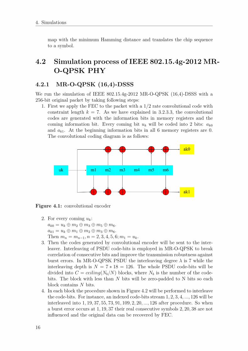
1. First we apply the FEC to the packet with a 1/2 rate convolutional code withconstraint length k = 7. As we have explained in 3.2.3.3, the convolutionalcodes are generated with the information bits in memory registers and thecoming information bit. Every coming bit uk will be coded into 2 bits: ak0and ak1. At the beginning information bits in all 6 memory registers are 0.The convolutional coding diagram is as follows:
Figure 4.1: convolutional encoder
2. For every coming uk:ak0 = uk ⊕m2 ⊕m3 ⊕m5 ⊕m6.ak1 = uk ⊕m1 ⊕m2 ⊕m3 ⊕m6.Then mn = mn−1, n = 2, 3, 4, 5, 6;m1 = uk.
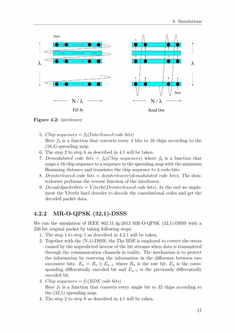
3. Then the codes generated by convolutional encoder will be sent to the inter-leaver. Interleaving of PSDU code-bits is employed in MR-O-QPSK to breakcorrelation of consecutive bits and improve the transmission robustness againstburst errors. In MR-O-QPSK PSDU the interleaving degree λ is 7 while theinterleaving depth is N = 7 ∗ 18 = 126. The whole PSDU code-bits will bedivided into C = ceiling(Nb/N) blocks, where Nb is the number of the code-bits. The block with less than N bits will be zero-padded to N bits so eachblock contains N bits.
4. In each block the procedure shown in Figure 4.2 will be performed to interleavethe code-bits. For instance, an indexed code-bits stream 1, 2, 3, 4, ..., 126 will beinterleaved into 1, 19, 37, 55, 73, 91, 109, 2, 20, ..., 126 after procedure. So whena burst error occurs at 1, 19, 37 their real consecutive symbols 2, 20, 38 are notinfluenced and the original data can be recovered by FEC.
16
4. Simulations
Figure 4.2: interleaver
5. Chip sequences = f5(Interleaved code bits)Here f5 is a function that converts every 4 bits to 16 chips according to the(16,4) spreading map.
6. The step 2 to step 8 as described in 4.1 will be taken.7. Demodulated code bits = f6(Chip sequences) where f6 is a function that
maps a 16-chip sequence to a sequence in the spreading map with the minimumHamming distance and translates the chip sequence to 4 code-bits.
8. Deinterleaved code bits = deinterleaver(demodulated code bits). The dein-terleaver performs the reverse function of the interleaver.
9. Decodedpacketbits = V iterbi(Deinterleaved code bits). In the end we imple-ment the Viterbi hard decoder to decode the convolutional codes and get thedecoded packet data.
4.2.2 MR-O-QPSK (32,1)-DSSSWe run the simulation of IEEE 802.15.4g-2012 MR-O-QPSK (32,1)-DSSS with a256-bit original packet by taking following steps:
1. The step 1 to step 5 as described in 4.2.1 will be taken.2. Together with the (N,1)-DSSS, the The BDE is employed to correct the errors
caused by the unpredicted inverse of the bit streams when data is transmittedthrough the communication channels in reality. The mechanism is to protectthe information by reserving the information in the difference between twosuccessive bits: En = Rn ⊕ En−1 where Rn is the raw bit; En is the corre-sponding differentially encoded bit and En−1 is the previously differentiallyencoded bit.
3. Chip sequences = f7(BDE code bits)Here f7 is a function that converts every single bit to 32 chips according tothe (32,1) spreading map.
4. The step 2 to step 8 as described in 4.1 will be taken.
17
4. Simulations
5. Demodulated code bits = f8(Chip sequences) where f8 is a function thatmaps a 32-chip sequence to a sequence in the spreading map with the minimumHamming distance and translates the chip sequence to 1 bit.
6. We can do the inverse function of the BDE to get the data before differentialcoding: Rn = En ⊕ En−1.
7. The step 8 and step 9 as described in 4.2.1 will be taken.
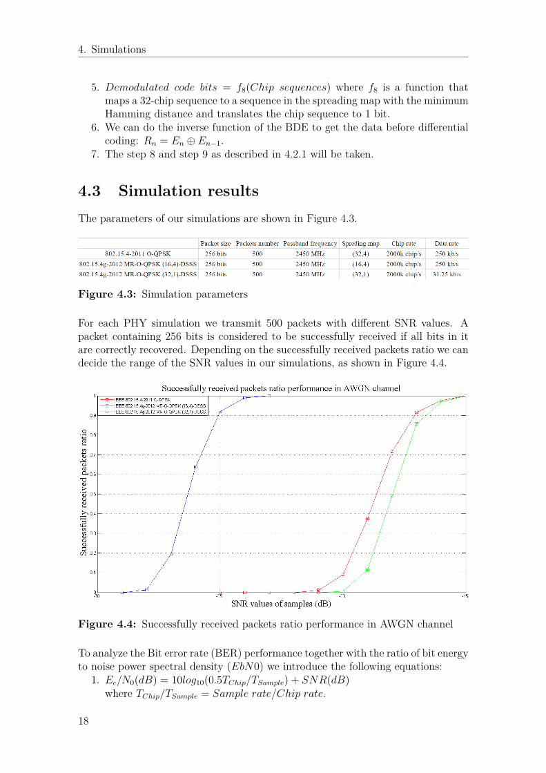
4.3 Simulation resultsThe parameters of our simulations are shown in Figure 4.3.
Figure 4.3: Simulation parameters
For each PHY simulation we transmit 500 packets with different SNR values. Apacket containing 256 bits is considered to be successfully received if all bits in itare correctly recovered. Depending on the successfully received packets ratio we candecide the range of the SNR values in our simulations, as shown in Figure 4.4.
Figure 4.4: Successfully received packets ratio performance in AWGN channel
To analyze the Bit error rate (BER) performance together with the ratio of bit energyto noise power spectral density (EbN0) we introduce the following equations:
1. Ec/N0(dB) = 10log10(0.5TChip/TSample) + SNR(dB)where TChip/TSample = Sample rate/Chip rate.
18
4. Simulations
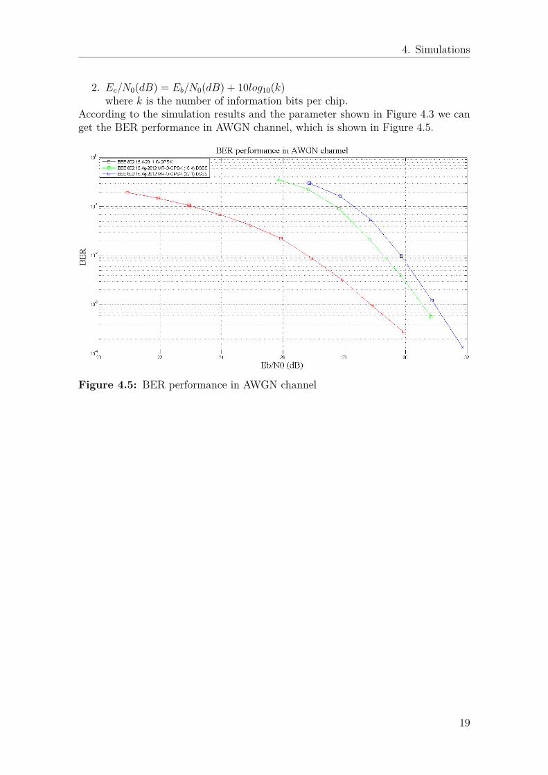
2. Ec/N0(dB) = Eb/N0(dB) + 10log10(k)where k is the number of information bits per chip.
According to the simulation results and the parameter shown in Figure 4.3 we canget the BER performance in AWGN channel, which is shown in Figure 4.5.
Figure 4.5: BER performance in AWGN channel
19

4. Simulations
20
5Improvement Proposals
5.1 Improvement proposal for IEEE 802.15.4-2011
According to the analysis and simulations of IEEE 802.15.4-2011, we have discusseda mechanism to improve the performance of the IEEE 802.15.4-2011 O-QPSK PHYin different application scenarios. We can introduce multiple spreading maps toIEEE 802.15.4-2011 O-QPSK PHY and a switching method to choose the optimalspreading map according to the specific application. This can be done by taking 4steps:
1. A counter keeps working in the PAN coordinator to calculate the PER duringa fixed interval.
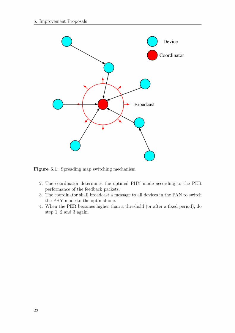
2. If the PER is higher than the threshold, the PAN coordinator shall broadcasta notification packet (as shown in Figure 5.1) to inform all devices in thePAN to increase the complexity of the spreading map (from (16,4) to (32,4)for instance). If the PER is much lower than the threshold the sink shallbroadcast a notification packet to inform all the devices in the PAN to decreasethe complexity of the spreading map.
3. Re-do step 2 until a satisfying PER is achieved or there is no more (or less)complex spreading map. Keep this spreading map for a fixed period.
4. After the fixed period, re-do step 1, 2 and 3.
5.2 Improvement proposal for IEEE 802.15.4g-2012
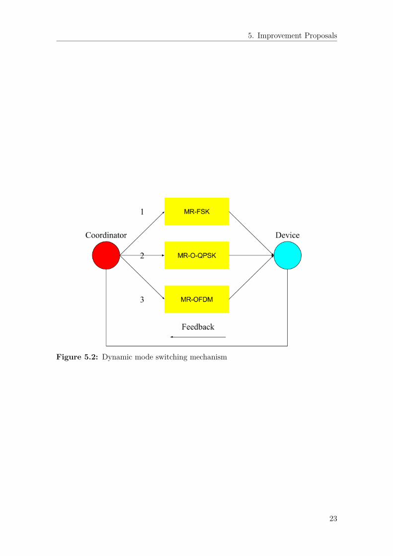
As we discussed before, the most valuable point provided by the IEEE 802.15.4g-2012 is that multiple PHY modes can be managed to serve in one PAN and modeswitch mechanism becomes possible in IEEE 802.15.4g-2012. So a dynamic modeswitch mechanism can be added to IEEE 802.15.4g-2012 to improve the performanceof the PAN in different application scenarios. Figure 5.2 shows the brief descriptionof this mechanism.This mechanism works as the following steps:
1. The PAN coordinator shall inform the neighboring devices that PHY teststarts by send a special notification packet. All devices that receive the noti-fication packet should switch the PHY to the specified one in the notificationpacket. Then the devices will send back a feedback packet, which is known bythe coordinator. This step will be repeated for three times and in each turnone of the three PHYs will be tested.
21
5. Improvement Proposals
Figure 5.1: Spreading map switching mechanism
2. The coordinator determines the optimal PHY mode according to the PERperformance of the feedback packets.
3. The coordinator shall broadcast a message to all devices in the PAN to switchthe PHY mode to the optimal one.
4. When the PER becomes higher than a threshold (or after a fixed period), dostep 1, 2 and 3 again.
22
5. Improvement Proposals
Figure 5.2: Dynamic mode switching mechanism
23

5. Improvement Proposals
24
6Conclusions
After analyzing IEEE 802.15.4-2011 and IEEE 802.15.4g-2012, we draw the con-clusion that the most impressive difference between them is that three multi-rateand multi-regional SUN PHYs are supported in IEEE 802.15.4g-2012. SUNs aredesigned to enable multiple applications to operate in the same location and sharethe same frequency band. The MPM scheme is specified in IEEE 802.15.4g-2012 forSUNs to facilitate the inter-PHY coexistence. The enhanced beacon and informationelements are introduced in MAC layer to support the MPM scheme.From the Figure 4.4 and Figure 4.5 we can see that the IEEE 802.15.4-2011 O-QPSK performs better than the IEEE 802.15.4g-2012 MR-O-QPSK (16,4)-DSSSand (32,1)-DSSS measured with BER performance in AWGN channel. The inter-leaving and BDE are introduced to the IEEE 802.15.4g-2012 to improve transmis-sion robustness against the burst errors and unpredicted inverse of the bit streams.In pure AWGN channels (like AWGN channels in our simulations) these functionscontribute quite little to transmission robustness improvements, but decrease theinformation bits in chips because of zero-padding and differential coding. The FECincreases the transmission robustness while the increasing complexity of the spread-ing map (from (16,4) to (32,4)) results in similar or even better effect.So we can draw the conclusion that in AWGN channel without burst errors or un-predicted inverse of the bit streams, IEEE 802.15.4-2011 O-QPSK performs betterthan IEEE 802.15.4g-2012 MR-O-QPSK when the data rate keeps the same. Butunder the circumstances where every turn of data transmissions takes considerableenergy consumption or the channel condition is really poor, IEEE 802.15.4g-2012MR-O-QPSK (32,1)-DSSS can be employed to ensure the probability of the suc-cessful transmission. In some emergency applications where the chances to sendout information are very valuable (fire alert, for instance) the IEEE 802.15.4g-2012MR-O-QPSK (32,1)-DSSS is more suitable than IEEE 802.15.4-2011 O-QPSK toprevent the transmission failure.By analyzing the simulation results we propose a spreading map switching mecha-nism that may improve the performance of the IEEE 802.15.4-2011 O-QPSK PHY indifferent application scenarios. Multi-rate and multi-regional PHYs are supported inIEEE 802.15.4g-2012. We propose a dynamic mode switching mechanism to choosethe optimal PHY mode in different application scenarios. For instance, the MR-O-QPSK can be switched to MR-OFDM when faced with a multi-path fading channel.MR-OFDM can be switched to MR-FSK to decrease the influence caused by Dopplereffect when the device starts to move fast. This mechanism could make better useof the MR-PHYs in IEEE 802.15.4g-2012.
25

6. Conclusions
26
Bibliography
[1] Radio Regulations, Edition of 2012. ITU-R. Retrieved 2014-11-10.[2] IEEE Standard for Local and metropolitan area networks-Part 15.4: Low-Rate
Wireless Personal Area Networks (LR-WPANs).[3] Khalid EL GHOLAMI, Kun-Mean HOU and Najib ELKAMOUN, "Enhanced
Superframe Structure of the IEEE802.15.4 Standard for Real-time Data Trans-mission in Star Network", International Journal of Computer Applications(0975-8887), Volume 51, No.15, August 2012.
[4] Sanjit Krishnan Kaul, "QPSK, OQPSK, CPM Probability Of Error for AWGNand Flat Fading Channels", Department of Electrical Engineering, Rutgers Uni-versity, Piscataway, NJ 08904.
[5] IEEE Standard for Local and metropolitan area networks-Part 15.4: Low-RateWireless Personal Area Networks (LR-WPANs), Amendment 3: Physical Layer(PHY) Specifications for Low- Data-Rate, Wireless, Smart Metering UtilityNetworks.
[6] Bob Watson, "FSK: Signals and Demodulation", 1980 Watkins-Johnson Com-pany Vol. 7 No. 5 September/October 1980.
27