
ANALYSIS - Online Project Management Nigeria - … · –Analysis of the proposed system . ... –A...
71
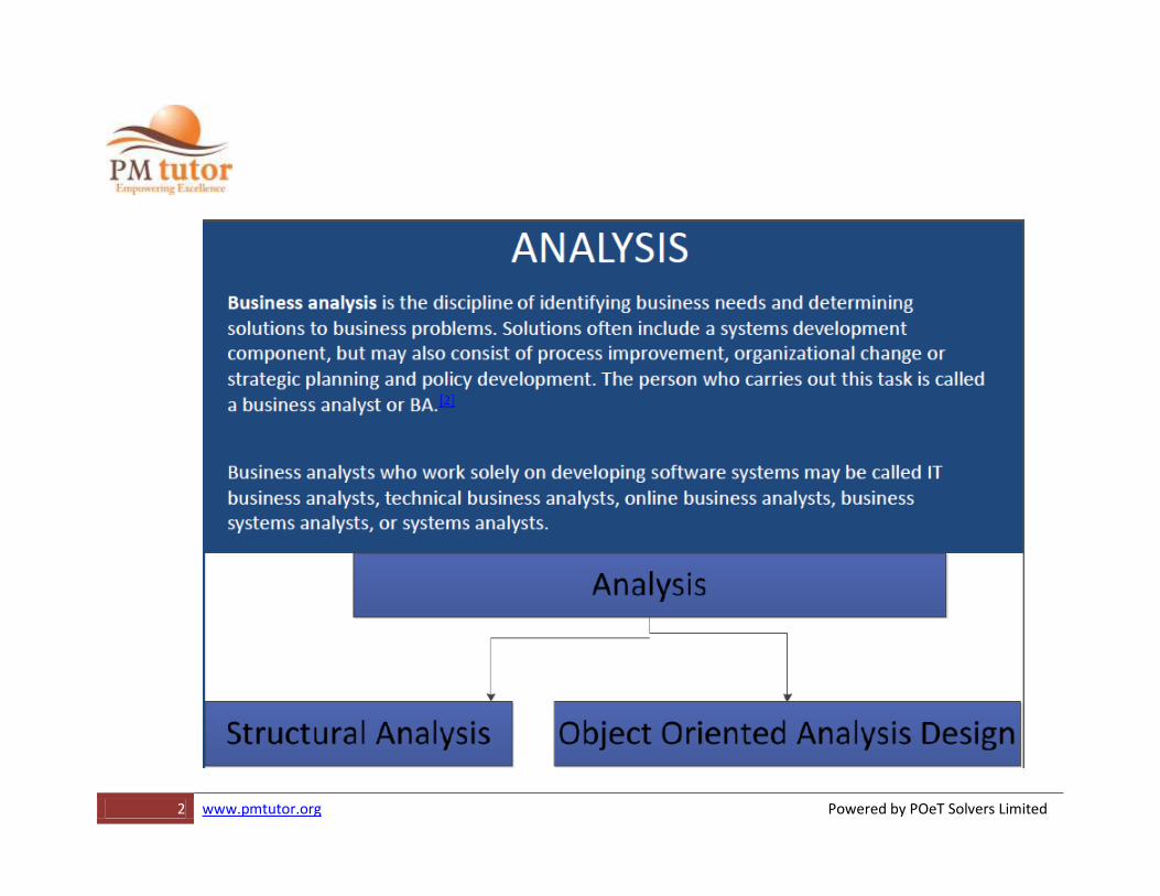
1 www.pmtutor.org Powered by POeT Solvers Limited ANALYSIS
-
Upload
trinhthuan -
Category
Documents
-
view
213 -
download
0
Transcript of ANALYSIS - Online Project Management Nigeria - … · –Analysis of the proposed system . ... –A...
4 www.pmtutor.org Powered by POeT Solvers Limited
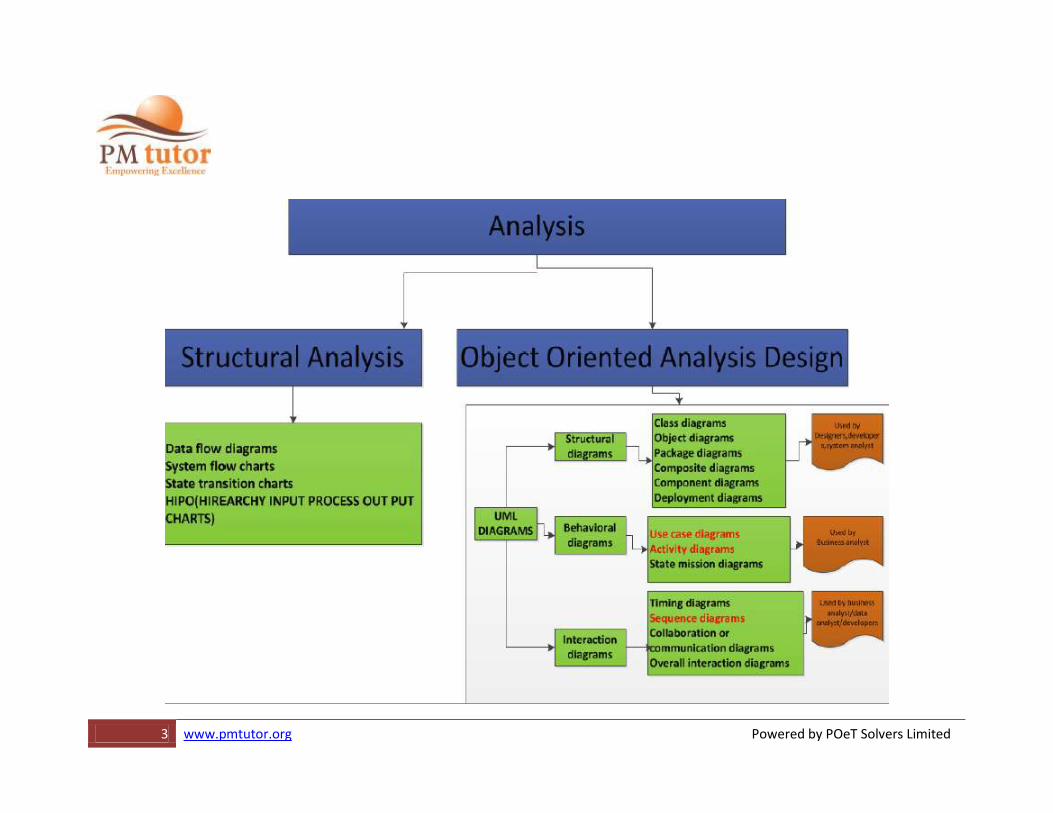
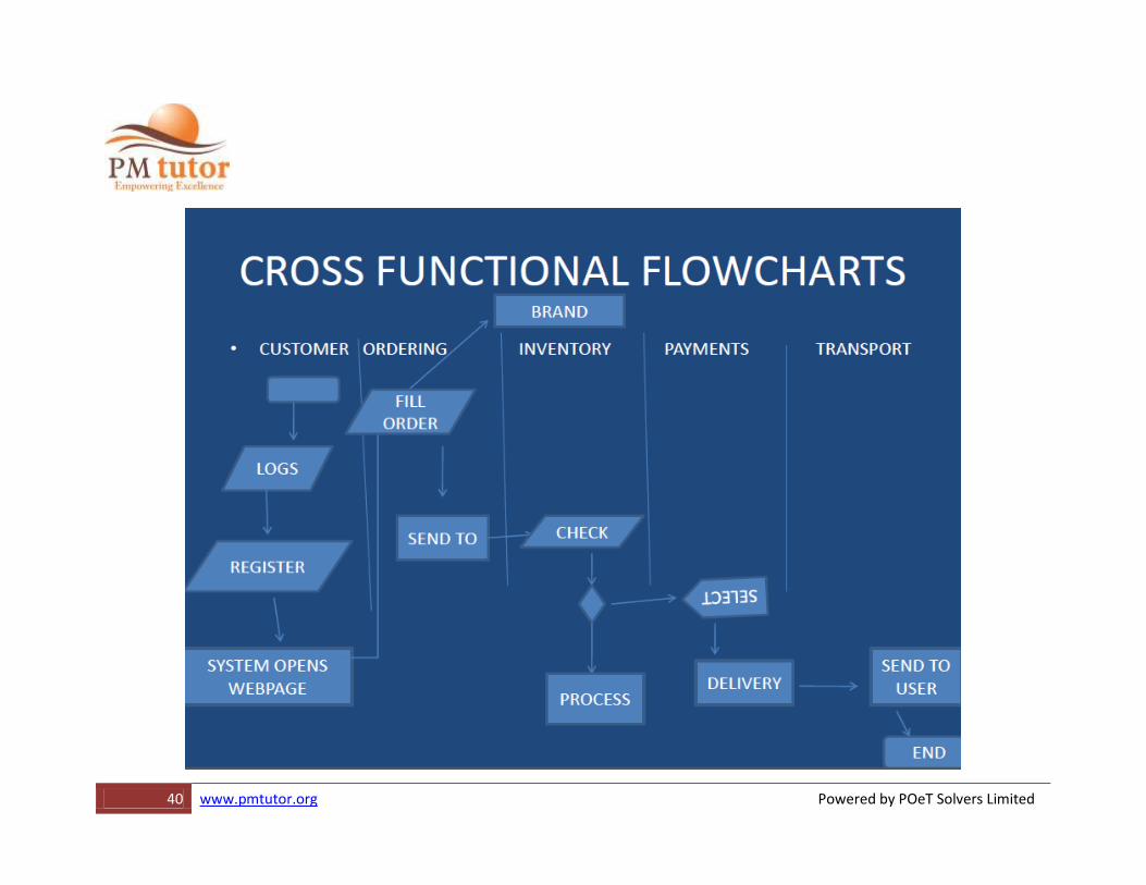
Structured analysis •A widely-used top-down method for defining system inputs, processes and outputs.
•It shows how information flows through a system, using several diagrams showing progressively more and more detail at each level.
•The primary tool of structured analysis is the Data Flow Diagram (DFD).
5 www.pmtutor.org Powered by POeT Solvers Limited
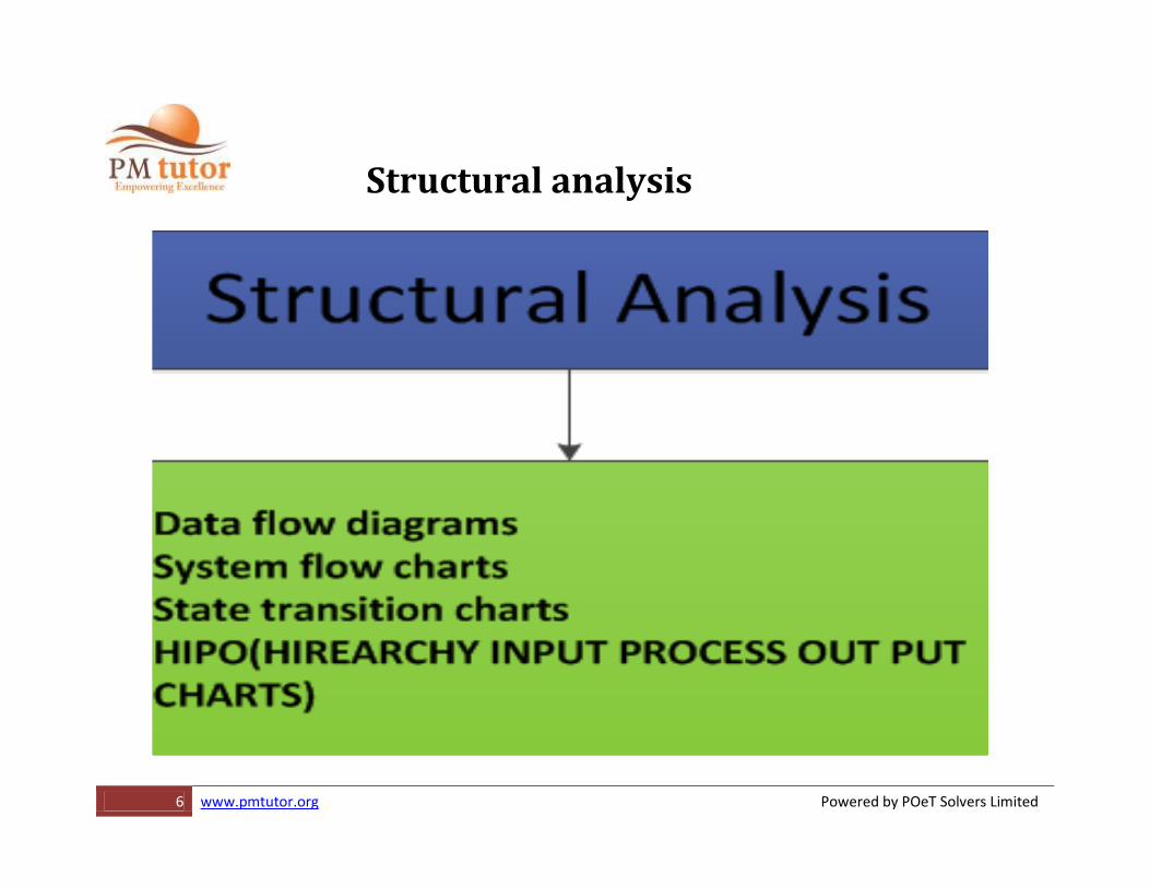
Structural analysis •Examination of the different components or elements that make up an organization or system, to discover their interrelationships and relative importance in the realization of its goals or purpose.
7 www.pmtutor.org Powered by POeT Solvers Limited
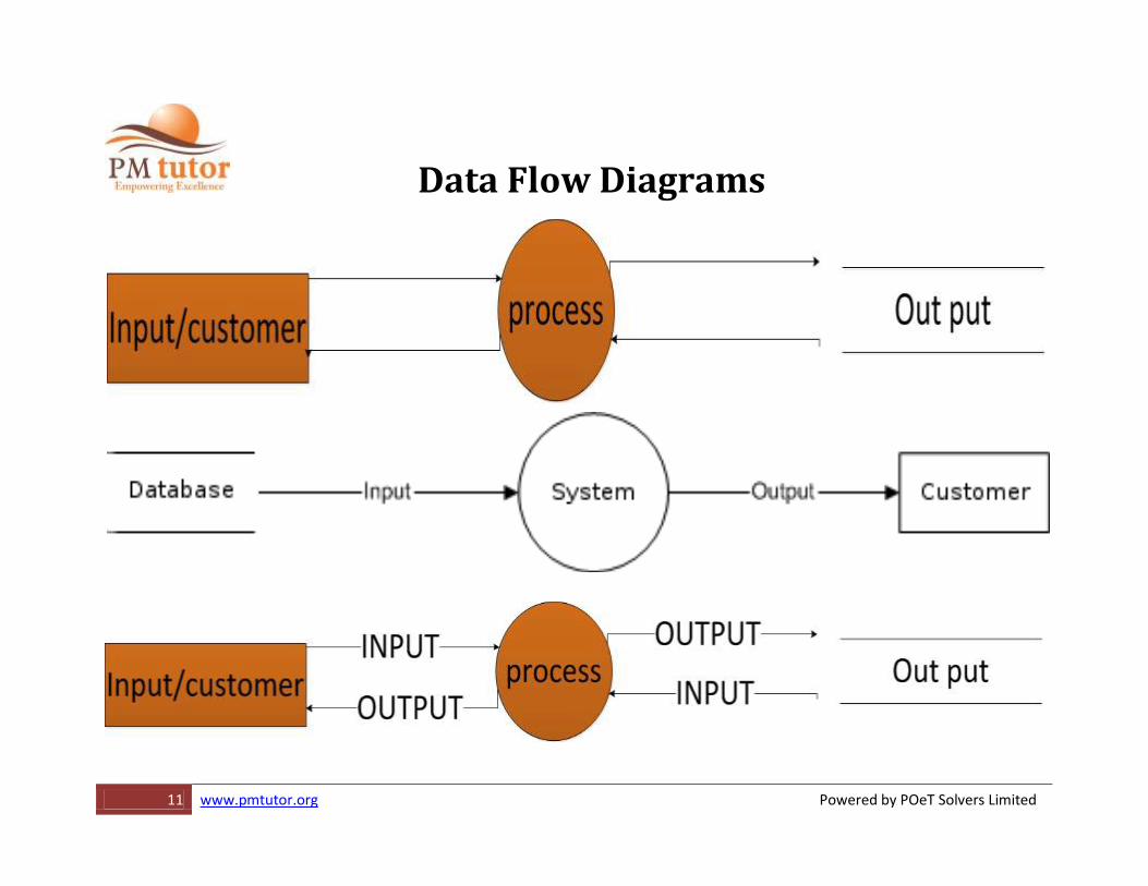
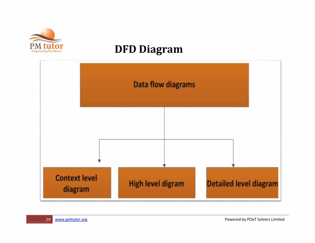
Data Flow Diagrams A structured analysis technique that employs a set of visual representations of the data that moves through the organization, the paths through which the data moves, and the processes that produce, use, and transform data.
8 www.pmtutor.org Powered by POeT Solvers Limited
Why Data Flow Diagrams? •Can diagram the organization or the system
•Can diagram the current or proposed situation
•Can facilitate analysis or design
•Provides a good bridge from analysis to design
•Facilitates communication with the user at all stages
9 www.pmtutor.org Powered by POeT Solvers Limited
Data flow diagrams •A data flow diagram (DFD) is a graphical representation of the "flow" of data through an information system, modeling its process aspects. Often they are a preliminary step used to create an overview of the system which can later be elaborated. [2]DFDs can also be used for the visualization of data processing (structured design). •A DFD shows what kinds of information will be input to and output from the system, where the data will come from and go to, and where the data will be stored. It does not show information about the timing of processes, or information about whether processes will operate in sequence or in parallel (which is shown on a flowchart).
12 www.pmtutor.org Powered by POeT Solvers Limited
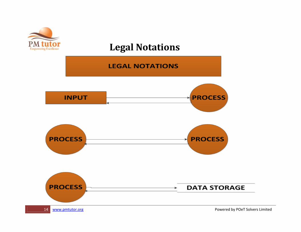
RULES FOR USING DFD •LEGAL RULES NOTATIONS
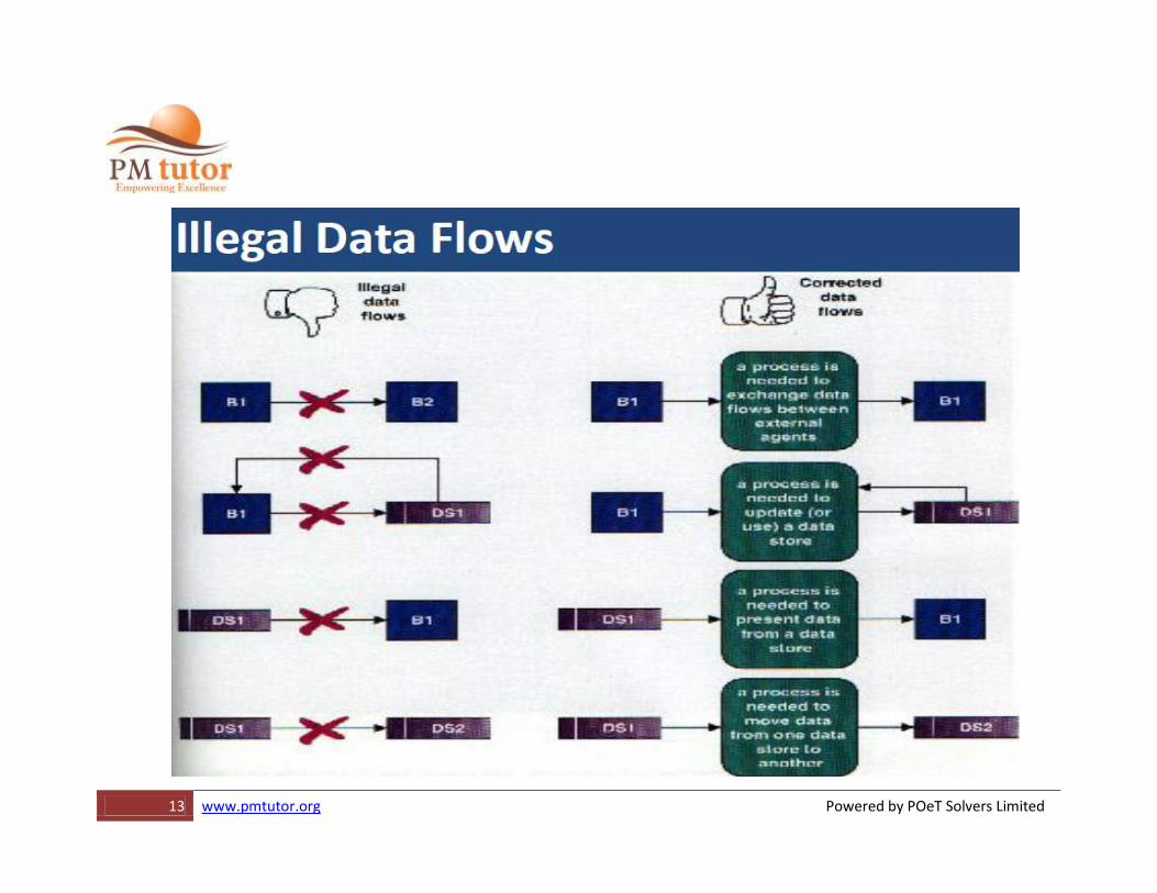
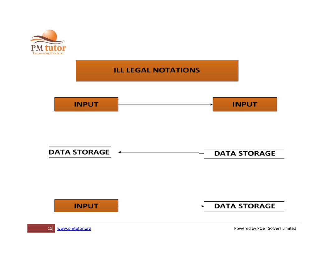
•ILLEGAL RULES NOTATIONS
16 www.pmtutor.org Powered by POeT Solvers Limited
DFD’S
•The dfd is essential tool for creating formal descriptions of business process and data flows
17 www.pmtutor.org Powered by POeT Solvers Limited
Advantages of the Data Flow Diagram Approach
•Four advantages over narrative explanations of data movement
–Freedom from committing to the technical implementation too early
–Understanding of the interrelationships of systems and subsystems
–Communicating current system knowledge to users
–Analysis of the proposed system
18 www.pmtutor.org Powered by POeT Solvers Limited
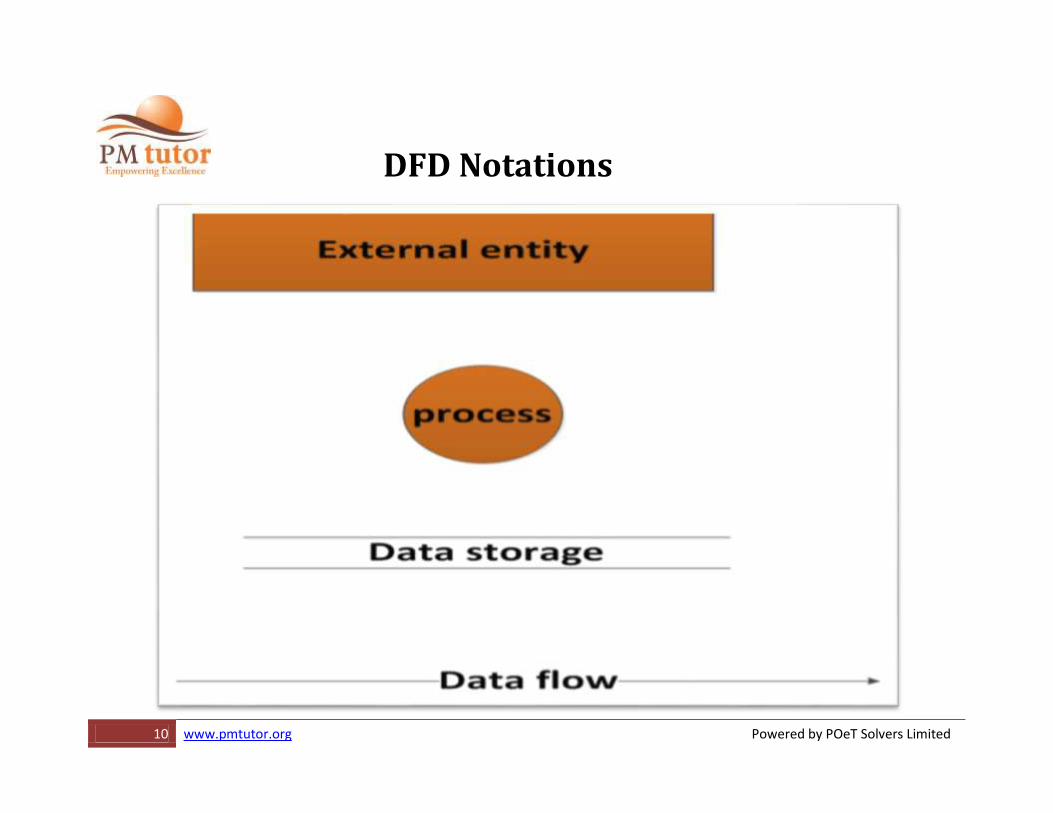
Data flow diagram symbols
•Four basic symbols are
–A double square for an external entity--a source or destination of data
–An arrow for movement of data from one point to another
–A rectangle with rounded corners for the occurrence of transforming process
–An open-ended rectangle for a data store
19 www.pmtutor.org Powered by POeT Solvers Limited
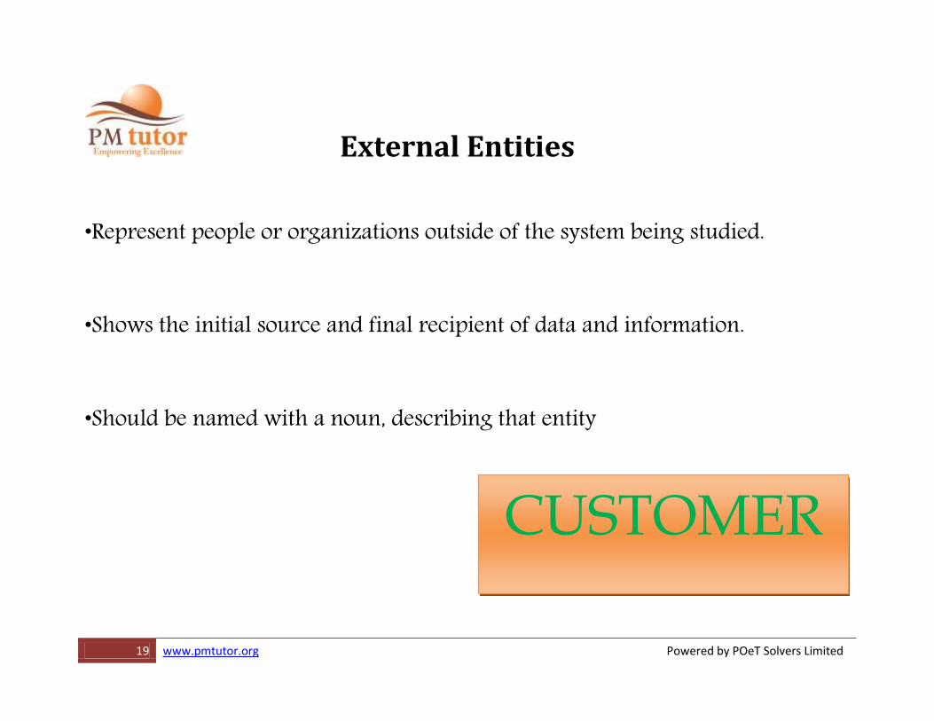
External Entities
•Represent people or organizations outside of the system being studied.
•Shows the initial source and final recipient of data and information.
•Should be named with a noun, describing that entity
CUSTOMER
20 www.pmtutor.org Powered by POeT Solvers Limited
•External entities may be –A person, such as CUSTOMER or STUDENT
–A company or organization, such as BANK or SUPPLIER
–Another department within the company, such as ORDER FULFILLMENT
–Another system or subsystem, such as the INVENTORY CONTROL SYSTEM
21 www.pmtutor.org Powered by POeT Solvers Limited
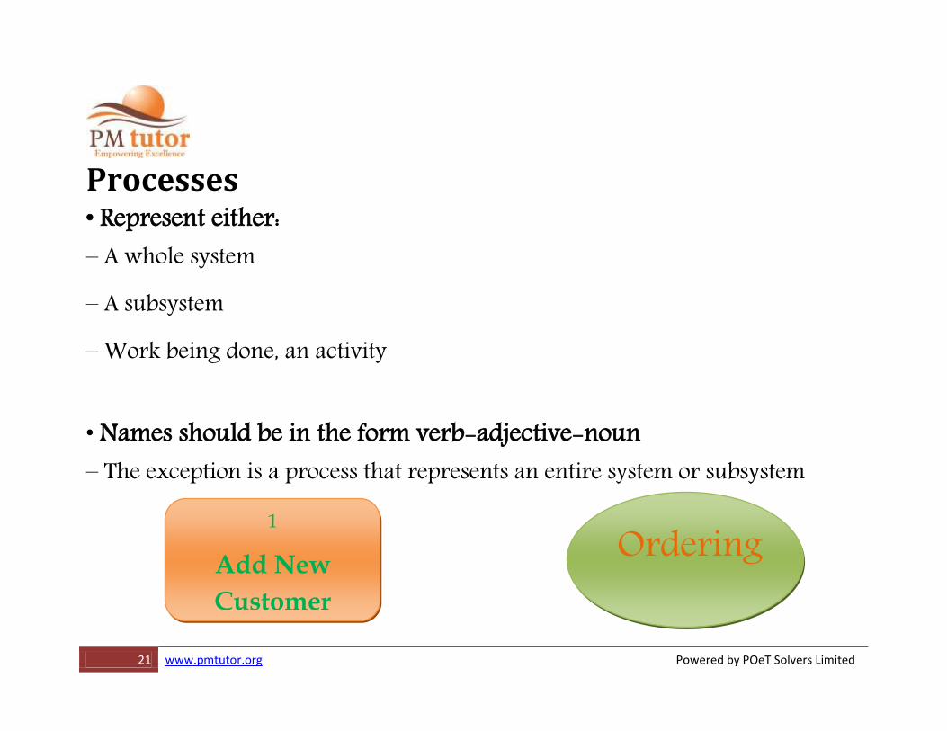
Ordering
Processes • Represent either: – A whole system
– A subsystem
– Work being done, an activity • Names should be in the form verb-adjective-noun – The exception is a process that represents an entire system or subsystem
1
Add New
Customer
22 www.pmtutor.org Powered by POeT Solvers Limited
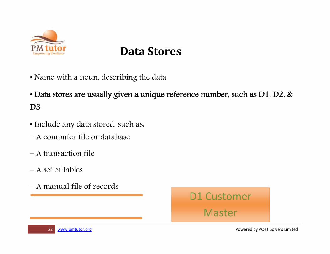
D1 Customer
Master
Data Stores • Name with a noun, describing the data
• Data stores are usually given a unique reference number, such as D1, D2, & D3
• Include any data stored, such as: – A computer file or database
– A transaction file
– A set of tables
– A manual file of records
23 www.pmtutor.org Powered by POeT Solvers Limited
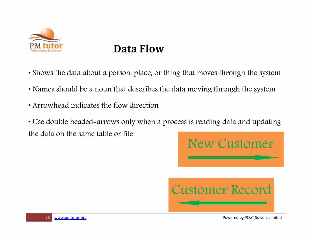
Data Flow • Shows the data about a person, place, or thing that moves through the system
• Names should be a noun that describes the data moving through the system
• Arrowhead indicates the flow direction
• Use double headed-arrows only when a process is reading data and updating the data on the same table or file
New Customer
Customer Record
25 www.pmtutor.org Powered by POeT Solvers Limited
Context Level Diagram
•Just one process
•All sources and sinks that provide data to or receive data from the process
•Major data flows between the process and all sources/sinks
•No data stores
26 www.pmtutor.org Powered by POeT Solvers Limited
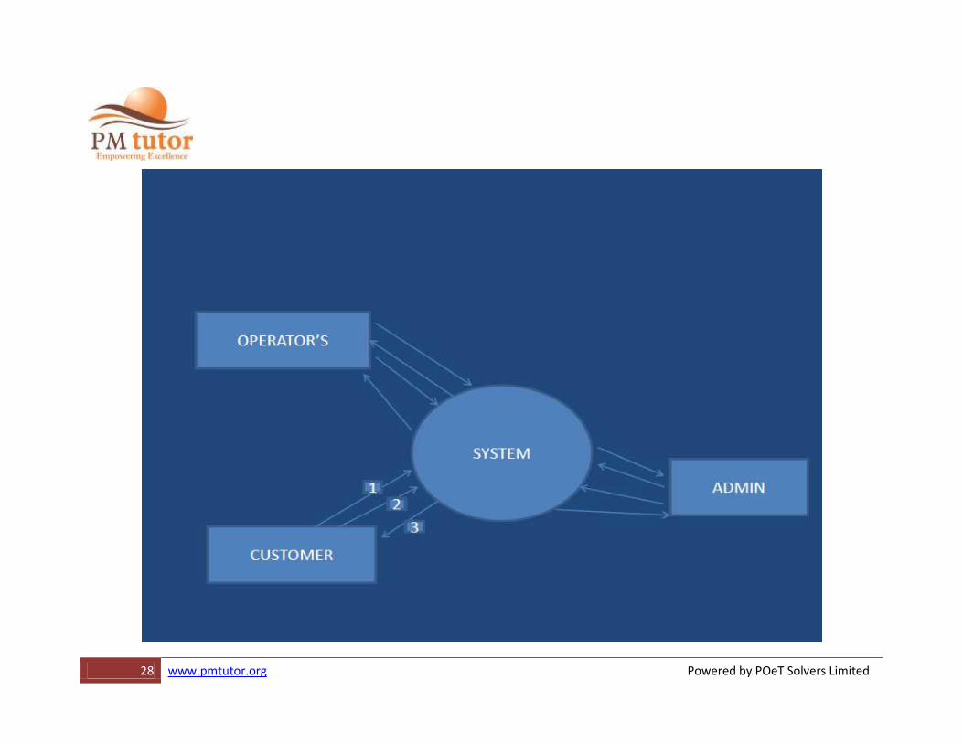
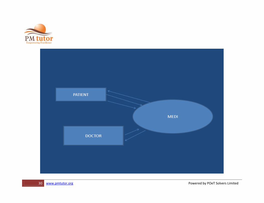
Context Level DFD’S •SHOWS INTERACTION BETWEEN EXTERNAL ENTITY TO MAIN SYSTEM OR PROCESS FOR THE PURPOSE OF CONSUMING AND PRODUCING DATA
•EXAMPLE
•ONLINE RAILWAY RESERVATION SYSTEM
27 www.pmtutor.org Powered by POeT Solvers Limited
Context Level Data Flow Diagram •Contains only one process, representing the entire system
•The process is given the number zero
•Allexternalentitiesareshownonthecontextdiagramaswellasmajordataflowtoandfromthem
•The diagram does not contain any data stores
29 www.pmtutor.org Powered by POeT Solvers Limited
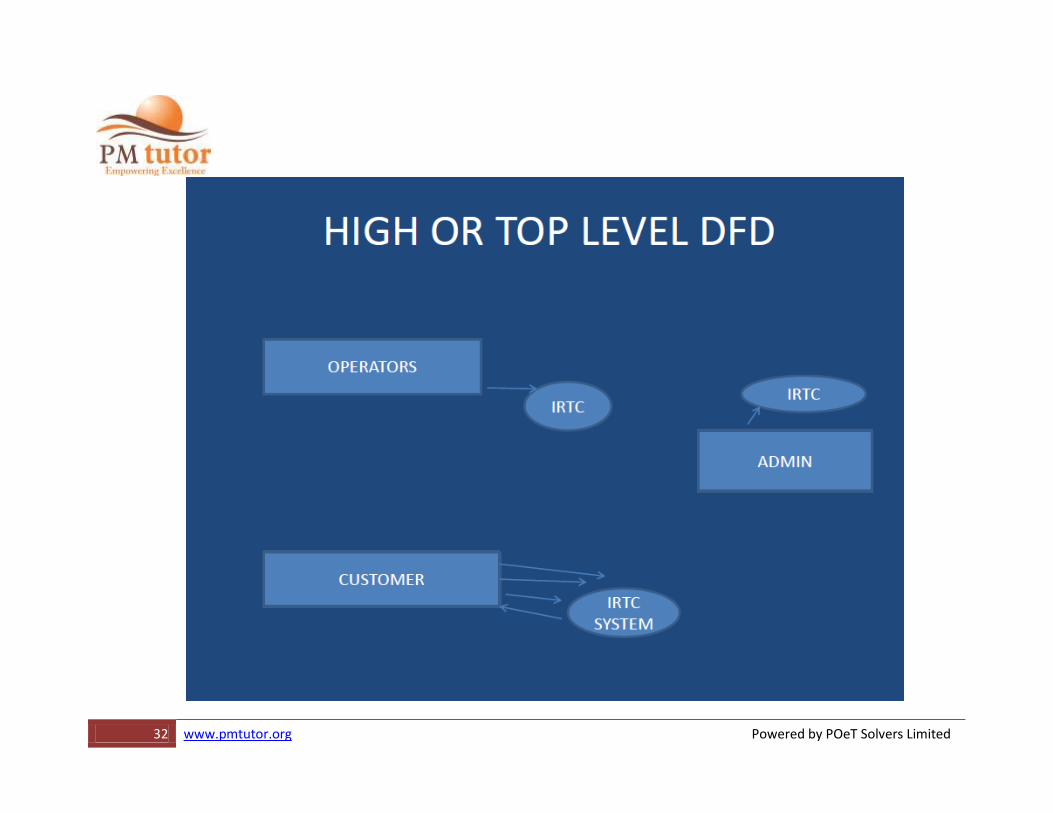
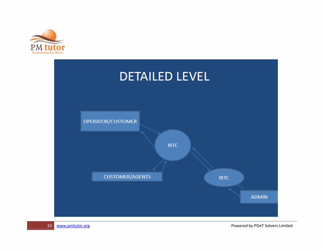
TOP-LEVEL DFD •Diagram is the explosion of the context level diagram
•Should include up to7 or 9 processes –Anymore will result in a clustered diagram
•Processes are numbered with an integer
•The major data store sandal external entities are included on Diagram
43 www.pmtutor.org Powered by POeT Solvers Limited
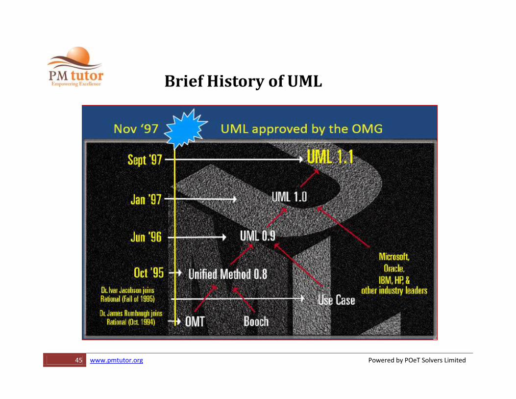
Unified Modeling LANGUAGE
Language for: Visualizing: Graphical models with precise semantics
Specifying: Models are precise, unambiguous and complete to capture all important Analysis, Design, and Implementation decisions.
Constructing: Models can be directly connected to programming languages, allowing forward and reverse engineering Documenting
44 www.pmtutor.org Powered by POeT Solvers Limited
Notions for UML Modeling •Booch …….Grady Booch
•OMT (Object Modeling Technology). Dr. James Rumbaugh
•Unified Modeling Language (UML) Booch, OMT, Jacobson Note: Standards Governing Boards such as ANSI & Object Management Group OMG)
46 www.pmtutor.org Powered by POeT Solvers Limited
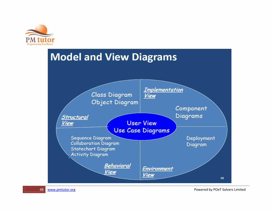
Diagrams in the UML
•Class diagram
•Object diagram
•Use case diagram
•Sequence diagram
•Collaboration diagram
•State chart diagram
•Activity diagram
•Component diagram
•Deployment diagram
47 www.pmtutor.org Powered by POeT Solvers Limited
Behavioral Modeling Use Cases Diagrams
Interactions Diagrams
Activity Diagrams
51 www.pmtutor.org Powered by POeT Solvers Limited
Benefits of Use Cases
•Captures functional requirements from user’s perspective
•Gives a clear and consistent description of what the system should do
•A basis for performing system tests
•Provides the ability to trace functional requirements into actual classes and operations in the system
52 www.pmtutor.org Powered by POeT Solvers Limited
What is a Use Case? •Created by Ivar Jacobson (1994)
•“A use case is a sequence of transactions in a system whose task is to yield a measurable value to an individual actor of the system”
•Describes WHAT the system (as a “Black Box”) does from a user’s perspective
•A set of scenarios tied together by a common user goal
•TheUseCaseModelisNOTaninherentlyobjectorientedmodelingtechnique
53 www.pmtutor.org Powered by POeT Solvers Limited
Use Case Principles •Describes required functionality in terms of the user –system
•Identifies external actors
•Identifies system boundary
•Describes scenarios of use
•Describes pre/post conditions
•Describes variants/exceptions
54 www.pmtutor.org Powered by POeT Solvers Limited
Use Case Hints •Use language of user
•Avoid implementation
•Get good scenarios
•Names single, identifiable and reasonably atomic behavior
•Describes flow of events clearly enough so outsider can follow
55 www.pmtutor.org Powered by POeT Solvers Limited
Use Case Hints…….
•Factors common behavior by pulling it from other use cases that it includes
•Factors variants by pushes such behavior into other use cases that extend it.
•Show only use cases that are important to understand system
•Show only actors that relate to use cases
•Specify actor names by specific roles
•Use top level diagram to show context
•Decompose top-level use cases to show requirements
•Group common use cases into packages
56 www.pmtutor.org Powered by POeT Solvers Limited
UML's Use Case Diagrams
•A Use Case model is described in UML (Unified Modeling Language) as one or more Use Case Diagrams (UCDs)
•A UCD has 4 major elements: –The system described
–The actors that the system interacts with
–The use-cases, or services, that the system knows how to perform
–The relationships between the above elements
57 www.pmtutor.org Powered by POeT Solvers Limited
Use Case •A use case is a coherent unit of externally visible functionality provided by a system and expressed by a sequence of messages
•Additional behavior can be shown with parent-child, extend and include use cases
•It is labeled with a name that the user can understand
58 www.pmtutor.org Powered by POeT Solvers Limited
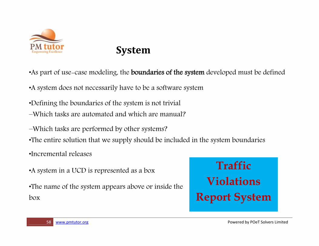
Traffic
Violations
Report System
System •As part of use-case modeling, the boundaries of the system developed must be defined
•A system does not necessarily have to be a software system
•Defining the boundaries of the system is not trivial –Which tasks are automated and which are manual?
–Which tasks are performed by other systems? •The entire solution that we supply should be included in the system boundaries
•Incremental releases
•A system in a UCD is represented as a box
•The name of the system appears above or inside the box
59 www.pmtutor.org Powered by POeT Solvers Limited
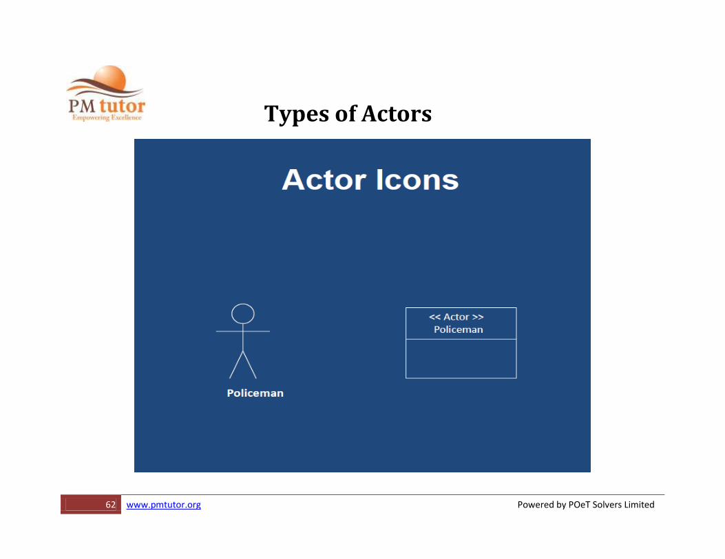
Actor •Someone or something that interacts with the system (exchanges information with the system)
•An actor represents a role played with respect to the system, not an individual user of the system
Example: –Policeman –Enters data –Supervisor –Allowed to modify/erase data –Manager –Allowed to view statistics.

60 www.pmtutor.org Powered by POeT Solvers Limited
•A single user may play more than one role •Actors have goals:
–Add a Traffic Violation
–Lookup a Traffic Violation
•Actors don’t need to be human –May be an external system that interfaces with the developed system
•An actor has a name that reflects its role
61 www.pmtutor.org Powered by POeT Solvers Limited
Types of Actors
•Primary Actor –Has goals to be fulfilled by system
•Supporting Actor
–Provides service to the system •Offstage Actor
–Interested in the behavior, but no contribution •In diagrams, Primary actors go on the left and others on the right.
63 www.pmtutor.org Powered by POeT Solvers Limited
Relationships between Actors •When several actors as part of their roles, also play a more generalized role, it is described as generalization •The behavior of the general role is described in an actor super-class •Thespecializedactorsinheritthebehaviorofthesuper-classandextenditinsomeway •Relationships between actors are not always necessary
64 www.pmtutor.org Powered by POeT Solvers Limited
Golden Rule of Use-Case Names
•Each use case should have a name that indicates what value (or goal) is achieved by the actor's interaction with the system •Here are some good questions to help you adhere to this rule:
Why would the actor initiate this interaction with the system? What goal does the actor have in mind when undertaking these actions? What value is achieved and for which actor?
65 www.pmtutor.org Powered by POeT Solvers Limited
Use-Case Name Example
•Excellent-Purchase Concert Ticket
•Very Good-Purchase Concert Tickets
•Good-Purchase Ticket (insufficient detail)
•Fair-Ticket Purchase (passive)
•Poor-Ticket Order (system view, not user)
•Unacceptable-Pay for Ticket (procedure, not process)
66 www.pmtutor.org Powered by POeT Solvers Limited
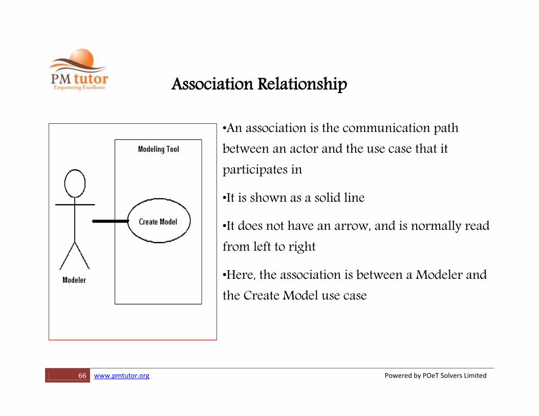
Association Relationship
•An association is the communication path between an actor and the use case that it participates in
•It is shown as a solid line
•It does not have an arrow, and is normally read from left to right
•Here, the association is between a Modeler and the Create Model use case
67 www.pmtutor.org Powered by POeT Solvers Limited
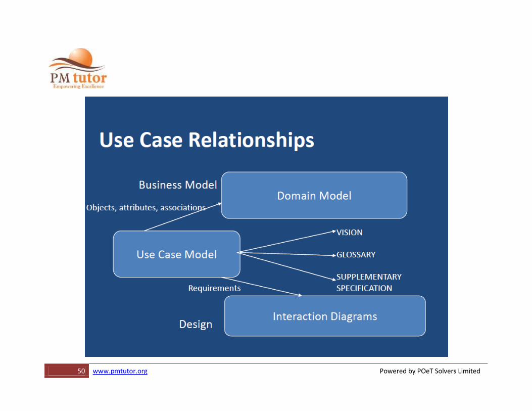
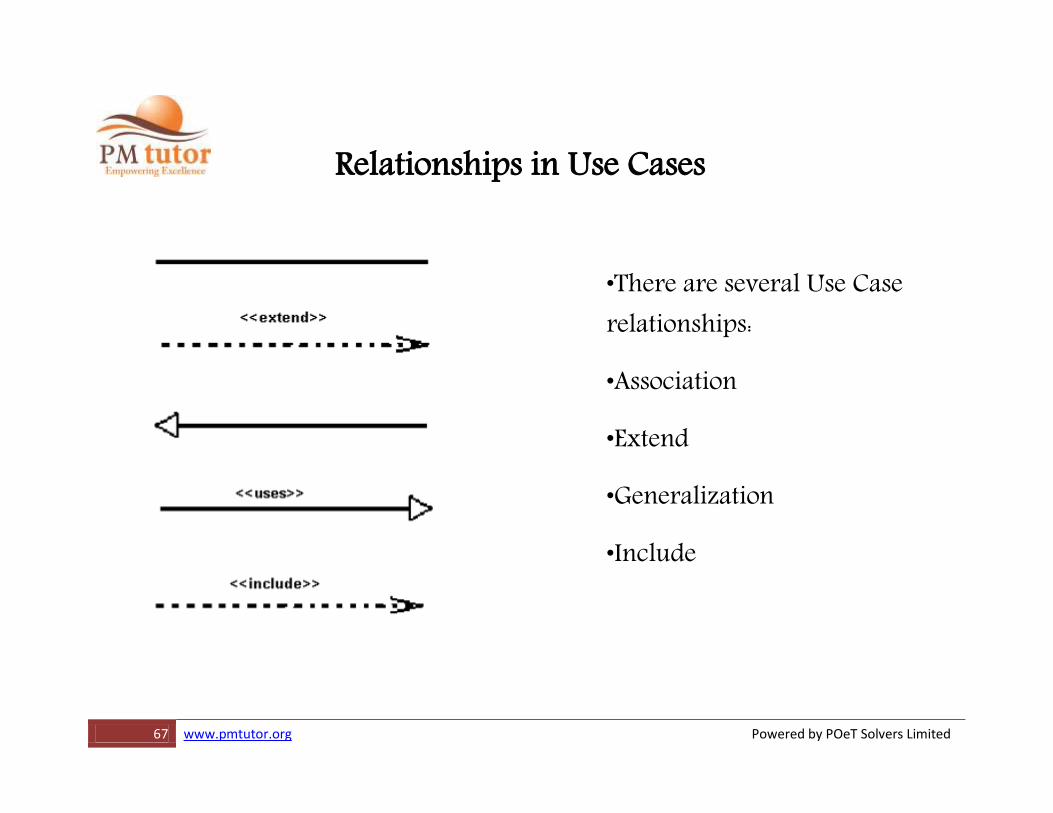
Relationships in Use Cases
•There are several Use Case relationships:
•Association
•Extend
•Generalization
•Include
68 www.pmtutor.org Powered by POeT Solvers Limited
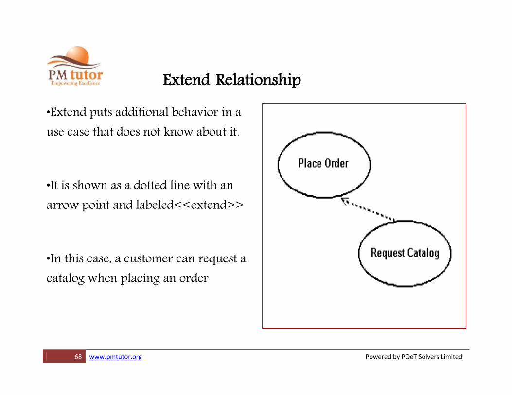
Extend Relationship
•Extend puts additional behavior in a use case that does not know about it.
•It is shown as a dotted line with an arrow point and labeled<<extend>>
•In this case, a customer can request a catalog when placing an order
69 www.pmtutor.org Powered by POeT Solvers Limited
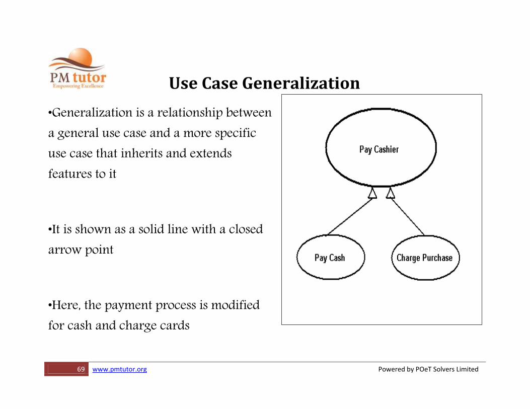
Use Case Generalization
•Generalization is a relationship between a general use case and a more specific use case that inherits and extends features to it
•It is shown as a solid line with a closed arrow point
•Here, the payment process is modified for cash and charge cards
70 www.pmtutor.org Powered by POeT Solvers Limited
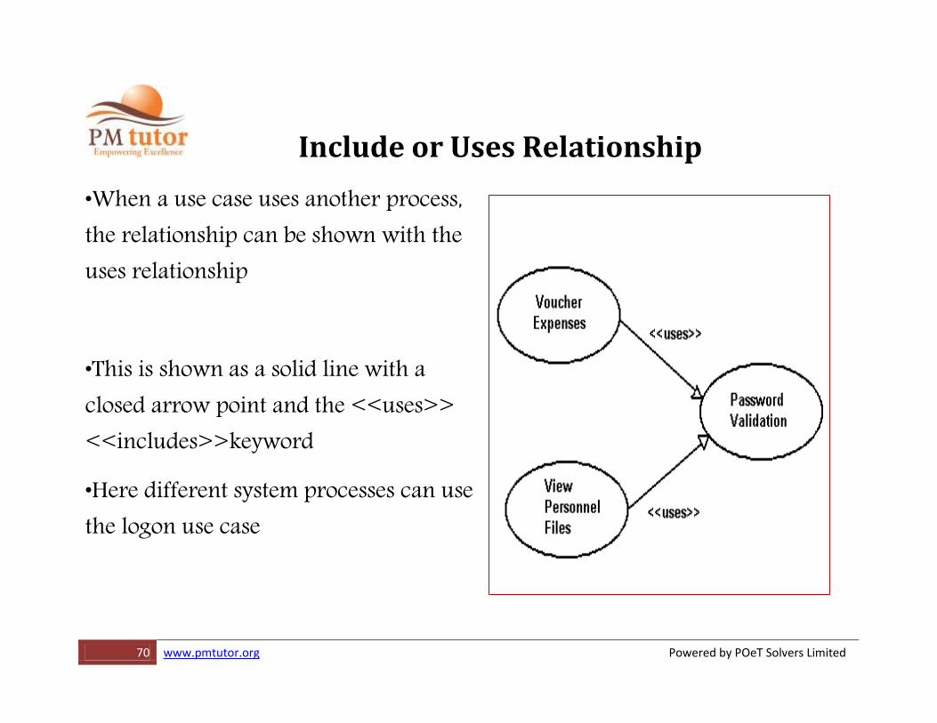
Include or Uses Relationship
•When a use case uses another process, the relationship can be shown with the uses relationship
•This is shown as a solid line with a closed arrow point and the <<uses>> <<includes>>keyword
•Here different system processes can use the logon use case