Analysis on Biomechanical Characteristics of Post...
16
INT. J. BIOAUTOMATION, 2016, 20(1), 99-114 99 Analysis on Biomechanical Characteristics of Post-operational Vertebral C5-C6 Segments Heqiang Tian 1* , Xuanxuan Zhu 1 , Jun Zhao 2 , Chunjian Su 1 1 Mechanical and Electronic Engineering College Shandong University of Science and Technology Qingdao 266590, China E-mails: [email protected] , [email protected] , [email protected] 2 State Key Laboratory of Robotics and System Harbin Institute of Technology Harbin 150080, China E-mail: [email protected] * Corresponding author Received: September 29, 2015 Accepted: February 15, 2016 Published: March 31, 2016 Abstract: Both anterior cervical decompression and fusion (ACDF) and artificial cervical disc replacement (ACDR) have obvious advantages in the treatment of cervical spondylosis. To analyze the operation results, it is absolutely necessary to study the biomechanics of the movement range of post-operational vertebral C5-C6 segments, especially the biomechanical characteristics in cervical tissues in actual movements. In this study, using the human vertebral 3D graph gained by imaging diagnosis (CT), a vertebral solid model is established by the 3D reconstruction algorithm and reverse engineering technology. After that, with cervical soft tissue structure added to the solid model and set with a joint contact mechanism, a finite element model with a complete, accurate cervical C5-C6 kinematic unit is constructed, based on relevant physiological anatomical knowledge. This model includes vertebral segments, an intervertebral disc, ligament and zygopophysis in the cervical C5-C6 kinematic unit. In the created vertebral finite element model, the model is amended, referring to ACDF and ACDR, and the load and constraint are applied to a normal group, a fusion group and a displacement group, so as to analyze the biomechanical characteristics of the cervical vertebra after ACDF and ACDR. By comparing the finite element simulation results of different surgeries, this paper is intended to evaluate the functions and biomechanical behaviors of the post-operational vertebra, and explore the influence of the operation on the biomechanical stability of the cervical vertebra. This will provide theoretical guidance for implementation and optimization of ACDF and ACDR. Keywords: Vertebra, Anterior cervical decompression and fusion (ACDF), Artificial cervical disc replacement (ACDR), Finite element analysis, Biomechanics. Introduction The anterior cervical decompression and fusion (ACDF) (Fig. 1a) is always a most effective means to treat myeleterosis and nerve root lesion caused by cervical disc herniation. However, this operation results in regression and instability of adjacent vertebral segments, and even recurrence or exacerbation of the original symptoms, because of sacrificing the vertebral activity degree in the lesion segment [2]. As a new means of treatment, an alternative to ACDF, the artificial cervical disc replacement (ACDR) [21] (Fig. 1b) is progressively being applied in clinics because of its ability to handle unstable adjacent vertebral segments after decompression, maintain the height of intervertebral space and restore the physiological activity of segments. Clinical features show that ACDR is superior to ACDF [5].
-
Upload
nguyenmien -
Category
Documents
-
view
215 -
download
0
Transcript of Analysis on Biomechanical Characteristics of Post...

INT. J. BIOAUTOMATION, 2016, 20(1), 99-114
99
Analysis on Biomechanical Characteristics
of Post-operational Vertebral C5-C6 Segments
Heqiang Tian
1*, Xuanxuan Zhu
1, Jun Zhao
2, Chunjian Su
1
1Mechanical and Electronic Engineering College
Shandong University of Science and Technology
Qingdao 266590, China
E-mails: [email protected], [email protected],
2State Key Laboratory of Robotics and System
Harbin Institute of Technology
Harbin 150080, China
E-mail: [email protected]
*Corresponding author
Received: September 29, 2015 Accepted: February 15, 2016
Published: March 31, 2016
Abstract: Both anterior cervical decompression and fusion (ACDF) and artificial cervical
disc replacement (ACDR) have obvious advantages in the treatment of cervical spondylosis.
To analyze the operation results, it is absolutely necessary to study the biomechanics of the
movement range of post-operational vertebral C5-C6 segments, especially the
biomechanical characteristics in cervical tissues in actual movements. In this study, using
the human vertebral 3D graph gained by imaging diagnosis (CT), a vertebral solid model is
established by the 3D reconstruction algorithm and reverse engineering technology.
After that, with cervical soft tissue structure added to the solid model and set with a joint
contact mechanism, a finite element model with a complete, accurate cervical C5-C6
kinematic unit is constructed, based on relevant physiological anatomical knowledge.
This model includes vertebral segments, an intervertebral disc, ligament and zygopophysis in
the cervical C5-C6 kinematic unit. In the created vertebral finite element model, the model is
amended, referring to ACDF and ACDR, and the load and constraint are applied to a
normal group, a fusion group and a displacement group, so as to analyze the biomechanical
characteristics of the cervical vertebra after ACDF and ACDR. By comparing the finite
element simulation results of different surgeries, this paper is intended to evaluate the
functions and biomechanical behaviors of the post-operational vertebra, and explore the
influence of the operation on the biomechanical stability of the cervical vertebra. This will
provide theoretical guidance for implementation and optimization of ACDF and ACDR.
Keywords: Vertebra, Anterior cervical decompression and fusion (ACDF), Artificial cervical
disc replacement (ACDR), Finite element analysis, Biomechanics.
Introduction The anterior cervical decompression and fusion (ACDF) (Fig. 1a) is always a most effective
means to treat myeleterosis and nerve root lesion caused by cervical disc herniation. However,
this operation results in regression and instability of adjacent vertebral segments, and even
recurrence or exacerbation of the original symptoms, because of sacrificing the vertebral
activity degree in the lesion segment [2]. As a new means of treatment, an alternative to
ACDF, the artificial cervical disc replacement (ACDR) [21] (Fig. 1b) is progressively being
applied in clinics because of its ability to handle unstable adjacent vertebral segments after
decompression, maintain the height of intervertebral space and restore the physiological
activity of segments. Clinical features show that ACDR is superior to ACDF [5].

INT. J. BIOAUTOMATION, 2016, 20(1), 99-114
100
a) ACDF b) ACDR
Fig. 1 ACDF and ACDR post-operational vertebral C5-C6 segments
Both ACDR and ACDF have obvious advantages in the treatment of cervical diseases.
Studying post-operational cervical biomechanical characteristics is a vital source to verify the
operation-applying effect, and is quite significant for the study of impaired vertebral column
mechanisms. Moreover, cervical vertebra is one of the most complex parts of the human body
in terms of geometry and movement characteristics, and its unique structure allows for its
special biomechanical functions. The biomechanical characteristics of the cervical vertebra
mainly include statics, kinetics and vertebral stability.
This paper is intended to study the biomechanical characteristics of the cervical vertebra,
intervertebral discs, ligaments and zygopophysis after both ACDF and ACDR in the
balancing state from statics. The functions and biomechanical behaviors of post-operational
cervical vertebra will be evaluated, and the influence of ACDF and ACDR on the vertebral
biomechanical stability will be explored. This will provide biomechanical principles as
guidance for implementation and optimization of both ACDF and ACDR.
Research status Current studies on extracorporeal specimens of ACDR focus on the moment control, and the
post-operational restoration effect is evaluated by analyzing the movement of vertebral
segments in a specific moment. In literature [1, 6], corresponding biomechanical models and
experimental methods are put forth where post-operational movement and stress changes of
the cervical vertebra are tested under the same torque by the use of a torque control device.
In addition, the movement of the human cervical vertebra is simulated in six working
conditions, using a self-made fixture and a universal tester by way of eccentric displacement
control in the literature [19], and the movement retaining ability and biomechanical
characteristics of the cervical vertebra are analyzed after ACDR and ACDF. Nuckley et al.
[18] investigated the biomechanics function and failure of the cervical vertebra across
multiple axes of loading throughout maturation by a correlational study design used to
examine the relationships of governing spinal maturation and biomechanical flexibility curves
and tolerance data using a cadaver human in vitro model. Conversely, the study on a cervical
biomechanical finite element has become an area of broad interest in the spinal research field.
Relative to extracorporeal specimens, this study deals with some complex problems such as
complicated cervical geometric shapes, uniformity of materials, changes of load, boundary
conditions, linear structures and sub-linear structures. Matsukawa et al. [14] quantitatively
evaluated the anchorage performance of the cortical bone trajectory by the finite element (FE)
method. Cao et al. [4] verified the position of occurrence of spinal compression fracture.
Li and Dai [13] established a 3D finite element model of the cervical vertebra to explore the

INT. J. BIOAUTOMATION, 2016, 20(1), 99-114
101
vertebral damage mechanism. Zhang et al. [26] analyzed the soft tissue stress distribution
after the cervical vertebra is damaged due to external factors, using finite element models of
head, cervical vertebra and soft tissues. Kolb et al. [11] analyzed biomechanical
characteristics of the risk of adjacent fractures and novel treatment modalities which lead to
greater biomechanical stability for osteoporotic vertebral fractures. Tchako and Sadegh [22]
held that the autogenous bone graft amount was available by comparing the stress change of
adjacent segments in transplantation of different bones in ACDF. Galbusera et al. [7] analyzed
the motion trails of artificial intervertebral discs after ACDR. Rousseau et al. [20] analyzed
the behavior of the functional spinal unit (FSU) with the variation of position of the center
and the size of the radius of a cervical ball-and-socket design by an experimentally validated
finite element model of the intact ligamentous cervical spine. Nishida et al. [16] used a
3-dimensional finite element method (3D-FEM) to analyze the stress distribution in
preoperative, posterior decompression and kyphosis models of Cervical ossification of the
posterior longitudinal ligament (OPLL). Objective cervical myelopathy due to ossification of
the posterior longitudinal ligament (OPLL ligament) is induced by static factors, dynamic
factors, or a combination of both. Nishida et al. [17] used a three-dimensional finite element
method (3D-FEM) to analyze the stress distributions in the cervical spinal cord under static
compression, dynamic compression, or a combination of both in the context of OPLL.
In addition, Cai et al. [3] carried out a texture analysis by the use of 27 bone tissue images for
osteoporosis recognition, which can be used to effectively recognize osteoporosis.
Cervical vertebra solid modeling The cervical vertebra refers to seven vertebrae (C1-C7) and their soft tissues on the upper side
of the vertebral column. The upper cervical spine (C1 and C2) is quite different from the
inferior cervical spine (C3-C7) in terms of geometric structure and mechanical characteristics.
There is a layer of hard cortical bone and cancellous bone with porous structure in the surface
of the cervical vertebra. The vertebral soft tissue includes the intervertebral disc and the
ligament. The intervertebral disc refers to the fibrous cartilage plate between two adjacent
segments of vertebrae which are connected by long and short ligaments. The cervical
vertebra, zygapophyseal joint, intervertebral disc and its ligament are the factors that provide
internal stability, while the muscles around a vertebra are not only external stability factors
but also contribute to internal stability. How to establish a complete solid model is the key to
conducting the biomechanical analysis of vertebra. A 3D vertebral solid model can be built by
3D reconstruction, solid generation and model verification mainly based on data from
computed tomography (CT) scanning.
Various scales of gray in a CT scan reflect different X-ray absorption capacities in different
human body tissues. The CT value for the skeleton, for example, is different from that of the
soft tissue. So, the different tissues and organs can be separated in human body CT images by
setting a gray threshold that segments CT images. The 3D reconstruction model of the
cervical vertebra reconstructed by the threshold segmentation algorithm, such as a marching
cubes algorithm (MC), is a 3D surface shell model made up of triangular patches. However,
its non-solid structure makes it unable to complete the follow-up biomechanical finite element
analysis, such as finite element grid division. For this reason, the model needs to be generated
as a solid one, which is accomplished utilizing the reverse engineering tool Geomagic
(Geomagic Inc, Research Triangle Park, NC, USA). A reasonable curved surface model is
initially formed, following four steps: smooth treatment, generating contour lines, generating
grids and fitting of the curve surface. Then the model surface is filled as a solid one as shown
in Fig. 2. It is observed from Fig. 2c that the reconstructed 3D geometric model has a gentle
and smooth curved surface; key anatomical parts such as zygopophysis and spinous process in
INT. J. BIOAUTOMATION, 2016, 20(1), 99-114
102
a spine have a reasonable structure arrangement according to the anatomical shape, and the
upper and lower surfaces of the cervical vertebra present a fit saddle surface. The error values
are obtained for all parts of the cervical curved surface model by comparing the geometric
size of the curved surface model with the geometric size of the original angular pitch model in
Fig. 2d. The error for the reconstructed model ranges from -0.191 mm to 0.846 mm, the
average distance deviation is 0.006 mm, and standard deviation is 0.025 mm. In fact, there are
some small errors with the triangular surface model corrected and smoothed in the
establishment of the cervical surface model, which can not cause too big impact on the model
accuracy in practice.
a) contour lines b) grids in model c) curved surfaces d) errors for model
Fig. 2 Construction of vertebral curved surfaces
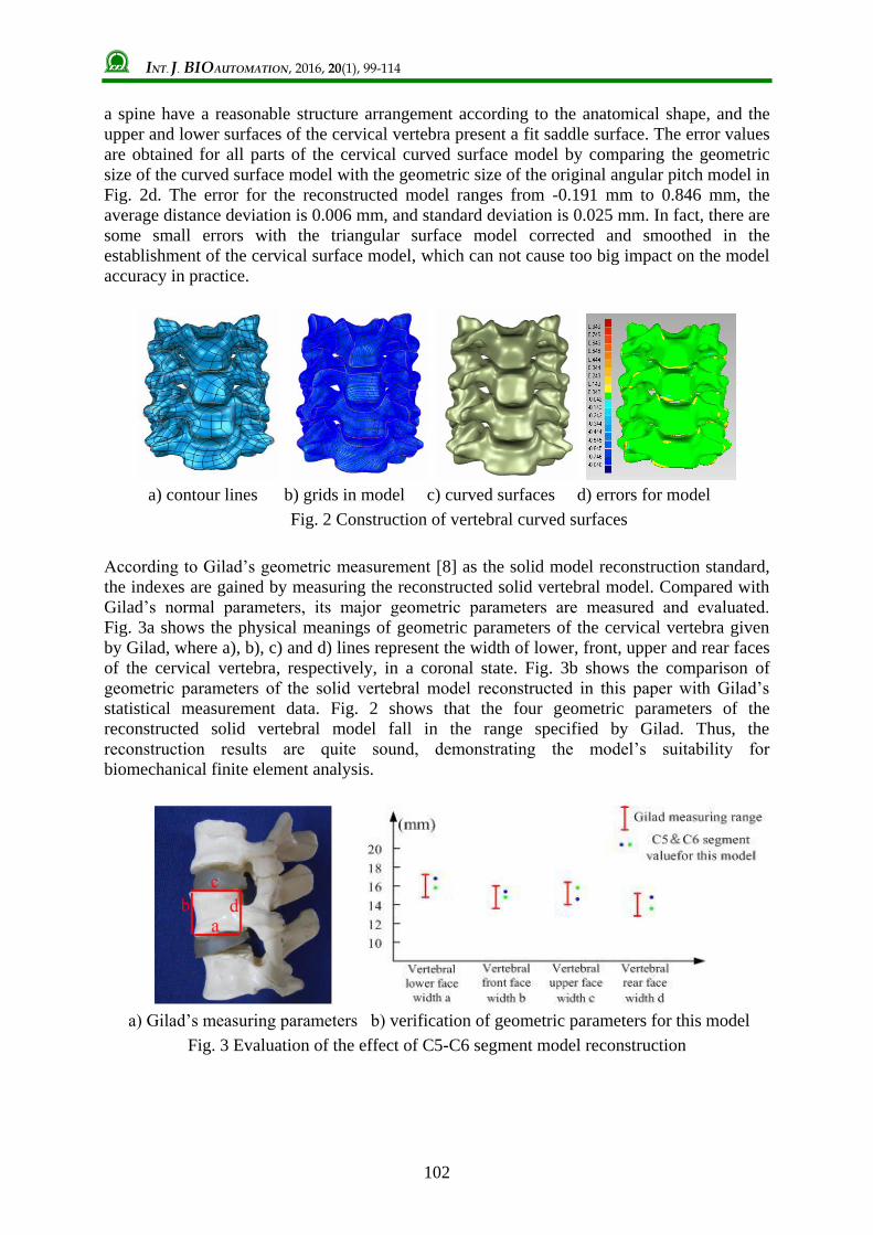
According to Gilad’s geometric measurement [8] as the solid model reconstruction standard,
the indexes are gained by measuring the reconstructed solid vertebral model. Compared with
Gilad’s normal parameters, its major geometric parameters are measured and evaluated.
Fig. 3a shows the physical meanings of geometric parameters of the cervical vertebra given
by Gilad, where a), b), c) and d) lines represent the width of lower, front, upper and rear faces
of the cervical vertebra, respectively, in a coronal state. Fig. 3b shows the comparison of
geometric parameters of the solid vertebral model reconstructed in this paper with Gilad’s
statistical measurement data. Fig. 2 shows that the four geometric parameters of the
reconstructed solid vertebral model fall in the range specified by Gilad. Thus, the
reconstruction results are quite sound, demonstrating the model’s suitability for
biomechanical finite element analysis.
a) Gilad’s measuring parameters b) verification of geometric parameters for this model
Fig. 3 Evaluation of the effect of C5-C6 segment model reconstruction

INT. J. BIOAUTOMATION, 2016, 20(1), 99-114
103
Vertebral finite element modeling This 3D finite element model of the cervical vertebra with a higher degree of biological
resemblance can be used to simulate the movements of human vertebrae such as bending and
rotation, as well as simulate and analyze the ACDR-oriented vertebral endplate cutting
process of the artificial cervical disc replacement (ACDR) [24], which is made up of a
vertebral finite element model, a soft tissue finite element model and a zygapophyseal joint
contacting model.
Creating a finite element model The cervical vertebrae, which have different densities, elasticity modulus and properties, even
in different positions of one vertebra, should be made of elastic materials with approximately
the same properties, and they are divided only into a cortical bone and a cancellous bone.
The spinal soft tissue includes a ligament and an intervertebral disc. Ligament can connect
two or more vertebrae, bearing only tension rather than pressure. The ligament between
vertebrae has more different elasticity modulus and sectional area, but each type of ligament
is linear to a certain extent in mechanical characteristics. According to data from literature
[15, 23, 26], the parameters for cortical and cancellous bone finite element models are shown
in Table 1. Here, the ligament is made by hand in the corresponding position of the vertebral
model based on anatomical data, and only the linear modulus unit shell41 that bears only
tension rather than pressure is used for simulation. Its thickness is set at 1 mm, and Poisson’s
ratio is set at 0.3; the sectional area and material properties for the other sections are shown in
Table 2. Different from the one-way mechanical properties of a ligament, the intervertebral
disc bears not only tension and pressure but also torsion. All constituent parts of the
intervertebral disc are simulated, using linear elastic materials and 8-node solid unit Solid45
in this paper. Parameters for the materials are shown in Table 3. There are two pairs of upper
and lower zygopophyses in the cervical vertebra. Both are coordinated with vertebral joints to
form a zygapophyseal joint. The zygapophyseal joints are separated mutually without
interaction in normal position of the vertebra. But in anteflexion, rotation or lateral bending of
the vertebra at a certain angle, zygapophyseal joints can contact each other to confine the
movement of vertebrae. The contacting pattern is generally applied to describe the transfer of
force between two contacting bodies and the change of three contacting states in different
loads; i.e., point to point, point to face and face to face. The zygapophyseal joint belongs to
the face-to-face contacting. In this paper, the interaction of zygapophyseal joints is simulated
in a 3D face-to-face contacting pattern with a friction coefficient of 0.1. The cervical C5-C6
segment finite element model is shown in Fig. 4. This model has 354,245 body units and
3,892 face units in total.
Table 1. Parameters for vertebral finite element model
Type
of bone
Elasticity modulus,
(MPa)
Poisson’s
ratio
Density,
(g/cm3)
Thickness,
(mm)
Type
of unit
Cortical bone 1200 0.29 1.83 0.5 Solid45
Cancellous bone 127 0.2 1 - Solid45

INT. J. BIOAUTOMATION, 2016, 20(1), 99-114
104
The normal vertebral model established earlier in the text should be further processed for
finite element simulation of ACDF; that is, the intervertebral disc between C5 and C6
segments is defined as an integral whole, and they should be connected together with upper
and lower vertebrae. Moreover, the excision of the anterior longitudinal ligament is simulated
in ACDF by removing the anterior longitudinal ligament model, so as to gain the ACDF finite
element model, as shown in Fig. 5a. The material parameters, unit type and grid division of
the fusion are the same as those of the cancellous bone. For the finite element simulation of
ACDR, the normal vertebral model established in the text above should be further refined.
So, the Bryan artificial cervical intervertebral disc is simulated using a curly top cylinder at a
diameter of 16 mm, a radius of upper and lower arc surfaces of 17 mm and a height of 8 mm.
The intercertebral disc model is set as an isotropic and liner-elastic solid45 solid unit, and its
Young’s modulus and Poisson’s ration are 5.9 MPa and 0.35. Referring to actual operation,
the anterior ligament is removed to gain the ACDR finite element model, as shown in Fig. 5b.
Table 2. Parameters for ligament materials
Type
Anterior
longitudinal
ligament
Posterior
longitudinal
ligament
Ligamenta
flavum
Supraspinous
and interspinous
ligaments
Young’s
elasticity
modulus /MPa
54.5 20 1.5 1.5
Sectional
area/mm2 6.1 5.4 50.1 13.1
Table 3. Parameters for materials of all parts of intervertebral disc
Tissue structure Nucleus
pulposus End plate Fiber ring
Elasticity modulus/MPa 1 500 4.2
Poisson’s ratio 0.499 0.4 0.45
Fig. 4 C5-C6 segment finite element model

INT. J. BIOAUTOMATION, 2016, 20(1), 99-114
105
a) ACDF b) ACDR
Fig. 5 ACDF and ACDR finite element models
Verifying finite element model The vertebral finite element model established in this paper is verified by using the
load-displacement curve method proposed in [12]. The interrelation of the cervical rotating
angle and moment is determined by fixing the lower face of the vertebra and applying the
moment to its upper face. In the cervical anteflexion-backward extension, the front axial
position vector n of the upper vertebra is taken as the measuring gauge on the cervical
sagittal face, and the included angle between vectors 1n and
2n is calculated before and after
load bearing. For the angles in bending and axial rotation of the vertebra, the kinetic rotating
angle for the finite element model is evaluated in action for different moments, based on the
section in the middle of the vertebral height, as shown in Fig. 6. According to the calculation
of the spatial vectors of the included angles, the rotating angle is expressed as:
1 2
1 2
cosn n
n n , (1)
where 1n is the the top fanterior axis position vector before load bearing; 2n – the top
fanterior axis position vector after load bearing; – the angle between 1n and 2n .
The degree of freedom (DOF) is fixed for the lower face of C6 segment in the established
model. The moments of anteflexion, backward extension, lateral bending and rotation are
applied respectively at 0.33, 0.5, 1.0, 1.5 and 2.0 Nm to the upper face of C5 segment.
The corresponding relation of rotating angle and applied moment of C5 segment is obtained
according to the calculating method above. After that, the results of this model are compared
with the results in [9, 12, 25].
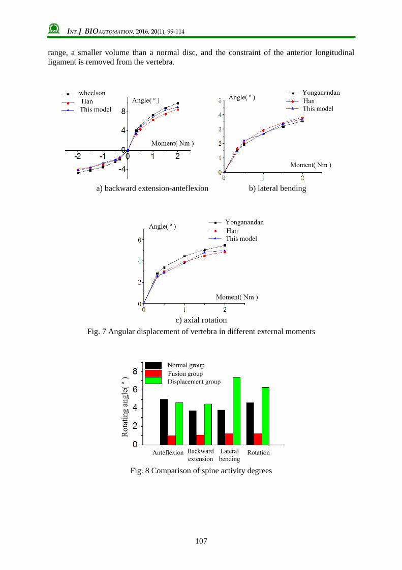
It is seen from Fig. 7 that the results of loading this model basically conform to reference
model data. The spinal rotating angle is linear in a single loading, and the rigidity of the
model in backward extension is greater than that in anteflexion. This is due to the
aygapophyseal joint face contacting limiting vertebral activity, which accords with the
previous study results. Thus, the finite element model established in this paper is reliable and
is suitable for follow-up biomechanical analysis.

INT. J. BIOAUTOMATION, 2016, 20(1), 99-114
106
a) anteflexion b) backward extension
c) calculation of rotating angle
Fig. 6 Calculation of rotating angles in vertebras
Simulation and analysis of vertebral biomechanical characteristics Load and constraints are applied to normal, fusion and intercalated disc displacement groups
so as to observe the degree of vertebral motion, ligament internal force and intervertebral disc
internal stress. For a normal model and models applied with ACDF and ACDR, all DOFs of
the lower face in their C6 segment are constrained and fixed respectively. The upper face of
C5 segment is applied by 1.5 Nm of moments of anteflexion, backward extension, lateral
bending and rotation, respectively, after it is applied by 73.6 N of axial pressure to simulate
head gravity.
Activity degree In four loading conditions of anteflexion, backward extension, lateral bending and rotation,
the comparison of the rotating angles of C5-C6 segments is shown in Fig. 8, which shows that
the range of cervical spine activity reduces greatly after ACDF compared with normal
conditions. The vertebral activity range in anteflexion, backward extension, lateral bending
and rotation reduces by 80%, 54%, 63% and 73%, respectively. However, the range of
vertebral activity in backward extension, lateral bending and rotation excluding anteflexion
after ACDR increases by 0.8°, 2.6°and 1.7° respectively. These results basically accord with
the follow-up imaging results after ACDR which retained the activity degree of the operated
segments. This is mainly because the artificial intervertebral disc itself has a wider activity
INT. J. BIOAUTOMATION, 2016, 20(1), 99-114
107
range, a smaller volume than a normal disc, and the constraint of the anterior longitudinal
ligament is removed from the vertebra.
a) backward extension-anteflexion b) lateral bending
c) axial rotation
Fig. 7 Angular displacement of vertebra in different external moments
Fig. 8 Comparison of spine activity degrees

INT. J. BIOAUTOMATION, 2016, 20(1), 99-114
108
Change of force to ligament The stress is analyzed for a single section of ligament using a finite element model, and the
results are shown in Fig. 9. It is found that in different loading conditions the acting force
transferred by the ligament changes, and the adjacent vertebrae are fixed and connected
together after ACDR, but the acting force reduces by 40-60%.
Compared with normal conditions, the force applied to the ligament in ACDR group increases
a little. This is mainly because the volume of the artificial intervertebral disc is smaller than
that of a normal human intervertebral disc so that it has a limited constraint to the moving
vertebrae.
a) force to ligament in anteflexion b) force to ligament in rotation
Fig. 9 Forces to ligament in anteflexion and rotation
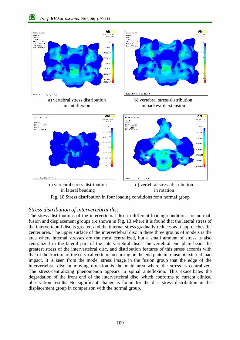
VonMises stress distribution of cervical vertebra Figs. 10, 11 and 12 offer images of the stress distribution cloud of C5-C6 segments of cervical
vertebrae in normal conditions, ACDF and ACDR, respectively.
After the ACDF is applied, the rotating center changes greatly. In the anteflexion-backward
extension-lateral bending-rotation moment, the stress of the fusion bone is greater than that of
the intervertebral disc in the normal group, increasing by 30%, 30%, 65% and 45%,
respectively. These are representations of cervical inability and accelerated degeneration of
the vertebra.
After the ACDR is applied, an artificial intervertebral disc can substitute for most of the
physiological movement functions of a normal disc. The rotation center in other groups is
close to that of the normal group, with the exception that in backward extension it is closer to
the fusion group’s rotation center, i.e., in the lower position of the upper vertebra. The stress
of upper and lower vertebrae changes greatly. This is basically in line with the situation where
the internal stress in the spine slightly increases by less than 6% for the spinal segments near
the artificial intervertebral disc reported in the finite element analysis literature [10].
INT. J. BIOAUTOMATION, 2016, 20(1), 99-114
109
a) vertebral stress distribution
in anteflexion
b) vertebral stress distribution
in backward extension
c) vertebral stress distribution
in lateral bending
d) vertebral stress distribution
in rotation
Fig. 10 Stress distribution in four loading conditions for a normal group
Stress distribution of intervertebral disc The stress distributions of the intervertebral disc in different loading conditions for normal,
fusion and displacement groups are shown in Fig. 13 where it is found that the lateral stress of
the intervertebral disc is greater, and the internal stress gradually reduces as it approaches the
center area. The upper surface of the intervertebral disc in these three groups of models is the
area where internal stresses are the most centralized, but a small amount of stress is also
centralized in the lateral part of the intervertebral disc. The vertebral end plate bears the
greatest stress of the intervertebral disc, and distribution features of this stress accords with
that of the fracture of the cervical vertebra occurring on the end plate in transient external load
impact. It is seen from the model stress image in the fusion group that the edge of the
intervertebral disc in moving direction is the main area where the stress is centralized.
The stress-centralizing phenomenon appears in spinal anteflexion. This exacerbates the
degradation of the front end of the intervertebral disc, which conforms to current clinical
observation results. No significant change is found for the disc stress distribution in the
displacement group in comparison with the normal group.

INT. J. BIOAUTOMATION, 2016, 20(1), 99-114
110
a) vertebral stress distribution
in anteflexion
b) vertebral stress distribution
in backward extension
c) vertebral stress distribution
in lateral bending
d) vertebral stress distribution
in rotation
Fig. 11 Stress distribution in four loading conditions for a fusion group
Conclusions This paper reconstructs an accurate and smoothness 3D solid model of the cervical vertebra
with smaller surface correction error by the reverse engineering method based on human
vertebral CT data. Its four geometric parameters fall within the acceptable range specified by
Gilad. On the basis of human spinal anatomical characteristics, the vertebral finite element
model is established for the cervical vertebra, vertebral intervertebral disc and ligament by
adding the intervertebral disc and ligament tissue and setting joint contacting features.
The precision of the model is verified by the load-displacement curve method. The C5-C6
segment finite element model is applied with constraint and external load. The characteristics
of spinal activity degree, ligament force, and vertebral internal stress are analyzed and
compared in a normal group, a fusion group and a displacement group. Some conclusions are
drawn and they are significant for clinical operation.

INT. J. BIOAUTOMATION, 2016, 20(1), 99-114
111
a) vertebral stress distribution
in anteflexion
b) vertebral stress distribution
in backward extension
c) vertebral stress distribution
in lateral bending
d) vertebral stress distribution
in rotation
Fig. 12 Stress distribution in four loading conditions for a displacement group
a) normal group
b) fusion group
c) displacement group
Fig. 13 Intervertebral disc internal pressure
Rotation Lateral bending Backward extension Anteflexion
Backward extension Rotation Lateral
bending
Anteflexion
Backward extension Rotation Lateral bending Anteflexion

INT. J. BIOAUTOMATION, 2016, 20(1), 99-114
112
Acknowledgements The authors would like to express appreciation for the financial supports from the Shandong
Province Young and Middle-aged Scientists Research Awards Fund (BS2013ZZ011),
the Qingdao application foundation research project (Youth special) (14-2-4-120-jch),
the Scientific Research Foundation of the Shandong University of Science and Technology for
Recruited Talents (2013RCJJ016), the National Natural Science Foundation of China
(51305241).
References 1. Barrey C., S. Campana, S. Persohn, G. Perrin, W. Skalli (2012). Cervical Disc Prosthesis
Versus Arthrodesis Using One-level, Hybrid and Two-level Constructs: An in vitro
Investigation, Eur Spine J, 21(3), 432-442.
2. Burkus J. K., R. W. Haid, V. C. Traynelis, P. V. Mummaneni (2010). Long-term Clinical
and Radiographic Outcomes of Cervical Disc Replacement with the Prestige disc: Results
from a Prospective Randomized Controlled Clinical Trial, J Neurosurg Spine, 13(3),
308-318.
3. Cai J., T. X.Wu, K. Zhou, W. Li (2015). Recognition of Osteoporosis Based on Texture
Analysis and a Support Vector Machine, International Journal Bioautomation, 19(1),
107-118.
4. Cao K. D., M. J. Grimm, K. H. Yang (2001). Load Sharing within a Human Luman
Vertebral Body Using the Finite Element Method, Spine, 26(12), E253-E260.
5. Coric D., P. D. Nunley, R. D. Guyer, D. Musante, C. N. Carmody, C. R. Gordon,
C. Lauryssen, D. D. Ohnmeiss, M. O. Boltes (2011). Prospective, Randomized,
Multicenter Study of Cervical Arthroplasty: 269 Patients from the Kineflex-C Artificial
Disc Investigational Device Exemption Study with a Minimum 2-year Follow-up,
J Neurosurg Spine, 15(4), 348-358.
6. Faizan A., V. K. Goel, A. Biyani, S. R. Garfinb, C. M. Bono (2012). Adjacent Level
Effects of Bi Level Disc Replacement, Bi Level Fusion and Disc Replacement Plus
Fusion in Cervical Spine – A Finite Element Based Study, Clin Biomech, 27(3), 226-233.
7. Galbusera F., C. M. Bellini, M. T. Raimondi, M. Fornari, R. Assietti (2008). Cervical
Spine Biomechanics Following Implantation of a Disc Prosthesis, Med Eng Phys, 30(9),
1127-1133.
8. Gilad I., M. Nissan (1986). A Study of Vertebra and Disc Geometric Relations of the
Human Cervical and Lumbar Spine, Spine, 11(2), 154-157.
9. Han K., C. Lu, J. Li, G.-Z. Xiong, B. Wang, G.-H. Lv, Y.-W. Deng (2011).
Biomechanical Research Using Three Dimensional Finite Element Method of Cervical
Artificial, European Spine Journal, 20(4), 523-553.
10. Kallemeyn N. A., S. C. Tadepalli, K. H. Shivanna, N. M. Grosland (2009). An Interactive
Multiblock Approach to Meshing the Spine, Computer Methods and Programs in
Biomedicine, 95, 227-235.
11. Kolb J. P., L. Weiser, R. A. Kueny, G. Huber, J. M. Rueger, W. Lehmann (2015). Cement
Augmentation on the Spine: Biomechanical Considerations, Orthopade, 44(9), 672-680.
12. Kumaresan S., N. Yoganandan, F. Pintar (1997). Age-specific Pediatric Cervical Spine
Biomechanical Responses: Three-dimensional Nonlinear Finite Element Models,
SAE Technical Paper 973319, doi: 10.4271/973319.
13. Li X. F., L. Y. Dai (2009). Three-dimensional Finite Element Model of the Cervical
Spinal Cord: Preliminary Results of Injury Mechanism Analysis, Spine, 34(11),
1140-1147.
14. Matsukawa K., Y. Yato, H. Imabayashi, N. Hosogane, T. Asazuma, K. Nemoto (2015).
Biomechanical Evaluation of the Fixation Strength of Lumbar Pedicle Screws Using

INT. J. BIOAUTOMATION, 2016, 20(1), 99-114
113
Cortical Bone Trajectory: A Finite Element Study, Journal of Neurosurgery Spine, 23(4),
471-478.
15. Meyer F., N. Bourdet, C. Deck, R. Willinger, J. S. Raul (2004). Human Neck Finite
Element Model Development and Validation against Original Experimental Data,
Stapp Car Crash Journal, 48, 177-206.
16. Nishida N., T. Kanchiku, Y. Kato, Y. Imajo, Y. Yoshida, S. Kawano, T. Taguchi (2014).
Biomechanical Analysis of Cervical Myelopathy due to Ossification of the Posterior
Longitudinal Ligament: Effects of Posterior Decompression and Kyphosis Following
Decompression, Experimental & Therapeutic Medicine, 7(5), 1095-1099.
17. Nishida N., T. Kanchiku, Y. Kato, Y. Imajo, Y. Yoshida, S. Kawano, T. Taguchi (2014).
Cervical Ossification of the Posterior Longitudinal Ligament: Biomechanical Analysis of
the Influence of Static and Dynamic Factors, J Spinal Cord Med, 38(5), 593-598.
18. Nuckley D. J., D. R. Linders, R. P. Ching (2013). Developmental Biomechanics of the
Human Cervical Spine, Journal of Biomechanics, 46(6), 1147-1154.
19. Pu T., C.-W. Li, B. Yan, Q.-H. Xue, F. Peng, Z.-H. Liao, W.-Q. Liu (2014). In vitro Study
on Biomechanical Comparison between Cervical Arthroplasty and Fusion, Journal of
Medical Biomechanics, 29(2), 105-112.
20. Rousseau M. A., X. Bonnet, W. Skalli (2008). Influence of the Geometry of a Ball-and-
socket Intervertebral Prosthesis at the Cervical Spine a Finite Element Study, Spine J,
33(1), E10-E14.
21. Sekhon L. H., J. R. Ball (2005). Artificial Cervical Disc Replacement: Principles, Types
and Techniques, Neurology India, 53(4), 445-450.
22. Tchako A., A. A. Sadegh (2009). Cervical Spine Model to Predict Injury Scenarios and
Clinical Instability, Sports Biomech, 8(1), 78-95.
23. Teo E. C., H. W. Ng (2001). Evaluation of the Role of Ligaments, Facets and Disc
Nucleus in Lower Cervical Spine under Compression and Sagittal Moments Using Finite
Element Method, Med Eng Phys, 23, 155-164.
24. Tian H., P. Yang, J. Zhao, C. Su (2015). Simulation and Analysis of ACDR-oriented
Vertebral Endplate Cutting Process, International Journal Bioautomation, 19(3), 335-350.
25. Wheeldon J., P. Khouphongsy, S. Kumaresan, N. Yoganandan, F. A. Pintar (2000).
Finite Element Model of Human Cervical Spinal Column, Biomedical Sciences
Instrumentation, 36, 337-342.
26. Zhang J. G., F. Wang, R. Zhou, Q. Xue (2011). A Three-dimensional Finite Element
Model of the Cervical Spine: An Investigation of Whiplash Injury, Med Biol Eng
Comput, 49(2), 193-201.
Heqiang Tian, Ph.D.
E-mail: [email protected]
Heqiang Tian received his Ph.D. degree in Mechanical Electronic
Engineering from the Harbin Institute of Technology, China, in
2011. Since 2012, he has been a lecturer in the Mechanical and
Electronic Engineering College, Shandong University of Science
and Technology, China. His research interests include biomedical
engineering and medical robotics.

INT. J. BIOAUTOMATION, 2016, 20(1), 99-114
114
Xuanxuan Zhu, B.Sc.
E-mail: [email protected]
Xuanxuan Zhu received his B.Sc. degree in Mechanical Design and
Manufacturing and Automation from the Qingdao Binhai
University. Now he is a postgraduate at the Mechanical and
Electronic Engineering College, Shannon University of Science
and Technology, China. His current research interests include
process simulation and numerical analysis.
Jun Zhao, B.Sc.
E-mail: [email protected]
Jun Zhao received his B.Sc. degree in Mechanical Electronic
Engineering from the Harbin Institute of Technology, Harbin,
China. His current research interest is in the field of biomedical
engineering.
Assoc. Prof. Chunjian Su, Ph.D.
E-mail: [email protected]
Chunjian Su received his Ph.D. degree in Material Forming and
Control Engineering from the Yanshan University, China, in 2007.
Since 2012, he has been an Associate Professor in the Mechanical
and Electronic Engineering College, Shandong University of
Science and Technology, China. His research interest is in the field
of material forming.