Analysis of wedge penetration clay -...
24
I l I I I BALIGH, M. M. & Scorr, R. F. (1976). Giotechnique 26, No. l, 185-208. Analysis of wedge penetration in clay MOHSEN M. BAUGH* and RONALD F. SCOTI A variety of devices designed to penetrate soil is used in soil engineering practice to measure soil properties or to emplace instrumentation, although the mechanics of the steady state penetration process is not well understood. Consequently the two-dimensional problem of steady state wedge penetration is examined. Solutions are obtained for wedge penetration in an ideal rigid plastic medium representing a clay. It is found that the solution requires the presence of a cavity behind the wedge, and the geometry of this cavity is established. A lower limit of the soil/wedge friction coefficient is derived, above which the wedge is considered rough. The force required to push the wedge is calculated as a function of wedge point angle and is shown to reach a minimum for a rough wedge at a point angle of about 67°. For axisymmetric penetration some finite element solutions were obtained and show that cone and wedge penetration mechanisms are similar. The mechanism and pat- terns of flow movement past the wedge for different point angles are demonstrated. Practical implica- tion of the results and their extension to axisymmetric cone penetration are discussed. Une variete d'appareils destines a penetrer dans le sol, est utilisee dans le pratique de la technique du sol, pour mesurer Jes proprietes du sol ou pour l'emplace- ment de )'instrumentation, bien que la condition per- manente de la mecanique du procCde de penetration ne soit pas bien comprise. Par consequent le prob- leme a deux dimensions de la condition permanente de la penetration de la cale, est examine. Des solu- tions sont obtenues pour la penetration de la cale dans un milieu ideal rigide-plastique, representant une argile. Il est decouvert que la solution exige la presence d'une cavite derriere la cale et la geometrie de cette cale est etablie. Une limite plus basse du coefficient du frottement du prisme est derivee, au- dessus de laquelle, la cale est consideree rugeuse. La force exigee pour pousser la cale, est calculee en fonc- tion de l'angle a la pointe de la cale, et est montree atteignant un minimum pour une cale rugeuse a angle a la pointe d'a peu pres 67°. Pour une penetration axisymetrique quelques solutions d'element fini ont ete obtenues et montrent que Jes mecanismes de la penetration au cone et de la cale sont semblables. Le mecanisme et Jes modeles pour le mouvement de l'ecoulement au-dela de la cale a de differents angles a la pointe, sont demontres. Une implication pratique des resultats et leur extension a la penetration au cone axisymetrique sont discutees. The capacity of soils to support without failure the loads imposed by engineering structures is of major concern in foundation design. Bearing capacity has therefore received considerable attention since soil mechanics developed into a science. Systematic study started with the pioneering work of Prandtl (1920) who provided the fundamental solution for the bearing capaci ty of a uniformly loaded strip surface footing on a rigid plastic homogeneous half space. The Prandtl solution is exact and therefore represents a milestone in the field. The material model, however, does not correspond to many soils. To make practical use of the solution Reissner (1924) and Terzaghi (1932) began a series of compromises in which exact solutions were sacrificed for the sake of introducing the effect of important parameters such as the depth of footing below the surface, the interaction of gravity on the mass of the soil, the slope and roughness of the footing base, and the deviation of the actual soil response from the theoretical model. Empirical and semi-empirical formulas as well as incomplete solutions covering a • Assistant Professor, Department of Civil Engineering, Massachusetts Institute of Technology, Cambridge, Massachusetts, USA. t Professor of Civil Engineering, California Institute of Technology, Pasadena, California, USA.
Transcript of Analysis of wedge penetration clay -...

I l I I I
BALIGH, M. M. & Scorr, R. F. (1976). Giotechnique 26, No. l, 185-208.
Analysis of wedge penetration in clay
MOHSEN M. BAUGH* and RONALD F. SCOTI
A variety of devices designed to penetrate soil is used in soil engineering practice to measure soil properties or to emplace instrumentation, although the mechanics of the steady state penetration process is not well understood. Consequently the two-dimensional problem of steady state wedge penetration is examined. Solutions are obtained for wedge penetration in an ideal rigid plastic medium representing a clay. It is found that the solution requires the presence of a cavity behind the wedge, and the geometry of this cavity is established. A lower limit of the soil/wedge friction coefficient is derived, above which the wedge is considered rough. The force required to push the wedge is calculated as a function of wedge point angle and is shown to reach a minimum for a rough wedge at a point angle of about 67°. For axisymmetric penetration some finite element solutions were obtained and show that cone and wedge penetration mechanisms are similar. The mechanism and patterns of flow movement past the wedge for different point angles are demonstrated. Practical implication of the results and their extension to axisymmetric cone penetration are discussed.
Une variete d'appareils destines a penetrer dans le sol, est utilisee dans le pratique de la technique du sol, pour mesurer Jes proprietes du sol ou pour l'emplacement de )'instrumentation, bien que la condition permanente de la mecanique du procCde de penetration ne soit pas bien comprise. Par consequent le probleme a deux dimensions de la condition permanente de la penetration de la cale, est examine. Des solutions sont obtenues pour la penetration de la cale dans un milieu ideal rigide-plastique, representant une argile. Il est decouvert que la solution exige la presence d'une cavite derriere la cale et la geometrie de cette cale est etablie. Une limite plus basse du coefficient du frottement du prisme est derivee, audessus de laquelle, la cale est consideree rugeuse. La force exigee pour pousser la cale, est calculee en fonction de l'angle a la pointe de la cale, et est montree atteignant un minimum pour une cale rugeuse a angle a la pointe d'a peu pres 67°. Pour une penetration axisymetrique quelques solutions d'element fini ont ete obtenues et montrent que Jes mecanismes de la penetration au cone et de la cale sont semblables. Le mecanisme et Jes modeles pour le mouvement de l'ecoulement au-dela de la cale a de differents angles a la pointe, sont demontres. Une implication pratique des resultats et leur extension a la penetration au cone axisymetrique sont discutees.
The capacity of soils to support without failure the loads imposed by engineering structures is of major concern in foundation design. Bearing capacity has therefore received considerable attention since soil mechanics developed into a science. Systematic study started with the pioneering work of Prandtl (1920) who provided the fundamental solution for the bearing capacity of a uniformly loaded strip surface footing on a rigid plastic homogeneous half space. The Prandtl solution is exact and therefore represents a milestone in the field. The material model, however, does not correspond to many soils. To make practical use of the solution Reissner (1924) and Terzaghi (1932) began a series of compromises in which exact solutions were sacrificed for the sake of introducing the effect of important parameters such as the depth of footing below the surface, the interaction of gravity on the mass of the soil, the slope and roughness of the footing base, and the deviation of the actual soil response from the theoretical model. Empirical and semi-empirical formulas as well as incomplete solutions covering a
• Assistant Professor, Department of Civil Engineering, Massachusetts Institute of Technology, Cambridge, Massachusetts, USA. t Professor of Civil Engineering, California Institute of Technology, Pasadena, California, USA.

186 M. M. BAUGH AND R. F. SC01T
NOTATION
B width of wedge a direction of first slip line
E Young's modulus of elasticity f3 direction of second slip line
e, unit vector in direction of co-ordinate r curve
axis x1 y half angle of the gap behind a rough
en unit normal vector of a surface wedge
e t unit tangent vector to a surface ji angle
G shear modulus 8 counterclockwise angle that an a line
H force per unit length of wedge makes with the horizontal
{} half angle of the wedge J jump in velocity coefficient of friction µ. k yield shear strength or apparent cohesion
l'-o minimum or critical coefficient of friction of clay
7 interface shearing stress L length of side of wedge a compressive hydrostatic stress p interface normal pressure a fJ components of stress tensor in frame X u translation velocity of wedge a , principal values of stress tensor x frame of reference Un normal stress y unconfined yield strength 2: curve
variety of important practical problems have been presented: Abdul-Baki, 1970; Brinch-Hansen, 1961 ; Broms, 1964; De Beer, 1965, 1970; Durgunoglu, 1973; Hansen, 1968; Hvorslev, 1970; Meyerhof, 1951, 1955, 1961a, b, 1963 ; Schmertmann, 1967, 1970; Skempton, 1951; Sokolovsky, 1960; Vesic, 1963, 1967. More recently numerical solutions have been obtained by Cox et al., 1961; Cox, 1962; Graham, 1968; Larkin, 1968; Lundgren and Mortensen, 1953; Nowatzki, 1971, 1972. The characteristic feature of most of these solutions, by and large, and the area in which they depart from exactness is the lack of consideration of the velocity field in the soil. This has been discussed by a number of investigators (Balla, 1962; GorbunovPossadov, 1965; Hu, 1970; Jumikis, 1961). The neglect of the velocity field seems to arise for the following reasons :
(a) conventional emphasis in soil mechanics is on stress (a look at any textbook on the subject will reveal that while stresses are of major concern, strains, displacements or velocities are less often mentioned; generally they are treated only when settlement problems arise);
(b) uncertanties associated with the deformational behaviour of soils make the accuracy of these solutions adequate for most practical applications;
(c) to obtain complete or exact solutions of problems involving materials with as complex properties as soils combined with the complicated geometry of practical situations is still a difficult task.
The lack of exact solutions invariably gives rise to disagreements between the results of different investigators. For example, the mechanics of the static cone penetration test as described by various theories which are summarized by Durgunoglu and Mitchell (1973) and compiled in detail by Sanglerat (1972) are evidence of the lack of agreement on the mechanism of penetration. In fact in the attempt to treat practical problems involving complex geometries and difficult material properties these theories have bypassed the usual stage of first obtaining a rigorous solution to a simple problem. Up to the present, the wedge penetration problem analogous to the Prandtl problem has not been solved. It is this situation which is considered here.
..
!
ANALYSIS OF WEDGE Pl!NlrrRATION IN CLAY 187
The deep penetration process is often considered to be a variation of the surface bearing capacity problem. This would be indeed correct if soil velocity fields or displacements could be neglected. However, when a complete picture of the two mechanisms is considered, a basic difference becomes evident. The bearing capacity of a surface footing is an incipient failure problem where no consideration is given to soil velocities once motion is started. On the other band, penetration must be considered a steady state problem in which the velocity of the soil, with respect to an observer moving with the wedge, is the same at any time after the movement bas begun. This fact imposes more severe requirements on penetration solutions. A realization of the difference between the two problems is essential if soil deformation is to be considered and a better understanding of the penetration mechfiniSm achieved. This understanding, in turn, is crucial for future designs and developments of penetrating objects. Such objects as cone penetrometers may be used either to measure existing states of stress or pore pressures, or to determine soil properties. The amount, extent and effect of disturbances caused by penetration and how these disturbances are affected by the geometry of the indenter, its surface roughness and other variables are all questions that can be answered, at least qualitatively, once the deformation mechanism is understood.
This Paper presents the theoretical portion of a study aimed at achieving a better understanding of deep penetration and includes an exact solution, within the scope of plasticity theory, of a simple penetration problem which is solved under the severe requirements of steady state motion. The problem solved is the plane strain penetration of an infinite rigid perfectly plastic medium by a rigid triangular wedge. Solutions are obtained for different wedge angles and either smooth or rough edges. Gravity and inertia forces are neglected as well as anisotropy, compressibility, non-homogeneity, internal friction and the geostatic state of stress. The solution should therefore apply reasonably well to the deep quasi-static penetration of a saturated clay for which the coefficient of earth pressure at rest is equal to unity, that is, the clay is initially subjected to an isotropic state of stress. Another paper (Baligh and Scott, 1975) presents a comparison between experimental results and the theoretical predictions herein.
From a practical standpoint, the solution to cone penetration, the axisymmetric counterpart of the plane strain solution presented here, would be more valuable. This axisymmetric problem has not been solved. However, the relation between the results for problems of axial symmetry and plane strain has been recognized or simply used in a variety of related problems.
The indentation of a half-space by a rigid indenter For the indentation of a rigid plastic half space by a rigid smooth fiat ended punch, plane
strain solutions by Prandtl (1920) and Hill (1950) for different modes of failure (velocity fields) give the same contact pressure at yield. The latter is 10% smaller than the one obtained by Shield (1955) in the case of a circular punch.
When the indenter is a smooth wedge and the half space is rigid plastic, Hill et al. (1947) obtained the plane strain solution. It was later checked and extended to various degrees of roughness by Grunzweig et al. (1952). When compared with the smooth cone solution by Lockett (1963), the plane strain solution was found to give an indentation pressure consistently lower by 10-40% depending on the half angle °' in the range 7r/2 ~ °' ~ 7r/3. When °' is less than 52·5°, Lockett's solution ceases to hold (because the assumed plastic field is no longer valid) and no comparison can be made. For blunt wedges ( °' larger than 7r/4, say) and for materials with low E/ Y ratio, where E is Young's modulus and Y the uniaxial yield strength, the measured deformations in the experiments of Dugdale (1953, 1954, 1955), Samuels et al. (1957), Hirst et al. (1969) and Atkins et al. (1965) showed that the deformation mode is more

188 M. M. BAUGH AND R. F. S<XYrr
(a) (b)
Fig. 1. Problem indenti6cation: (a) wedge completely surrounded by clay; (b) penetration of wedge with gap behind
of a compression nature than the cutting assumed by perfect plasticity and which was experimentally verified for small {},
Along suggestions by Bishop et al. (1945), March (1964) applied Hill's theory for the expansion of a spherical cavity in a semi-infinite elastic plastic medium to Vicker's hardness test. The same idea of using the results of the expansion of a cylindrical and a spherical cavity in a half space to simulate the indentation by a blunt wedge and a pyramid was later used by Johnson (1970). The results in both cases compare favourably with test results by previous investigators. The contact pressure in the axially symmetric case is larger than in plane strain by zero to 14 % depending on the parameter a= E/ Y cot {} in the range 7 :5 a :5 100 ( {} enters the analysis by determining the geometry of the expanding cavity).
Expansion of cavities in an infinite medium and the point resistance of piles On lines parallel to the case of the half-space, and initiated by Bishop et al. (1945), the point
resistance of deep foundations has been interpreted in terms of the pressure required to expand a spherical or cylindrical cavity in an infinite medium. In this context the succession of work done by Gibson (1950), Chadwick (1959), and Skempton et al. (1961) led to the most general formulation of the problem by Vesic (1972). It allows the infinite medium to behave in an elastic plastic manner, have internal friction and be compressible when in a plastic stage. For materials with no internal friction and incompressible in a plastic state, the comparison between the pressure required to expand both spherical and cylindrical cavities shows that the axisymmetric pressure is roughly 33% greater than the plane strain pressure when G/ Y lies between 2·5 and 250, where G is the shear modulus. Moreover, while the effect of compressibility (in the plastic stage) on the difference between plane strain and axial symmetry pressures is small, the effect of internal friction is considerable (Vesic, 1972) as is also, of course, observed in the surface footing case.
The bearing capacity of shallow and deep foundations On the basis of intuition, experiments, and less rigorous solutions, the analogy between axial
symmetry and plane strain has been used by earlier investigators (Terzaghi, 1943; Meyerhof, 1951). Empirical factors are used to determine the bearing capacity of axially symmetric foundations from analysis of plane strain problems. A value of l ·2 is commonly taken for the conversion factor.
Although an exact solution for the axisymmetric problem was obtained in few of these examples, the analytical and experimental results consistently indicated that pressures or equivalent forces in the axisymmetric cases were somewhat higher than those derived for the corresponding plane strain situation. As a preliminary guide, therefore, it is suggested that the

ANALYSIS OF WEDGE PENETRATION IN CLAY 189
pressures calculated for the plane rough wedge in the conditions dealt with here (0 < 2{} < TT/2), can be converted to pressures in the corresponding axisymmetric problem by multiplication by a factor of 1·1. For very blunt wedges (W> TT/2), the factor may be higher, up to about 1 ·3.
In this study, after the theoretical solutions for the wedges bad been checked experimentally (Baligh and Scott, 1975) the finite element technique was used, first, to bridge the gap between plasticity solutions and experiments, and second, to extend the plane strain case of the wedge to its axisymmetric counterpart, the cone. Finite element solutions, however, are limited to the study of incipient failure and cannot yet be used to simulate the steady state condition because of the large strains involved.
WEDGE PENETRATION OF AN INFINITE MEDIUM AS A STEADY STA TE PROBLEM IN PERFECT PLASTICITY
Seeking a complete and rigorous solution for deep penetration the simplest, yet still relevant problem of indentation is here considered. Fig. l(a) shows a rigid symmetric triangular wedge with half-angle {}, side length L, width B and infinite length (perpendicular to the plane of the figure) which is pushed at a constant velocity U in the direction shown through an infinite medium. The velocity of the wedge is small enough not to give rise to any significant inertia forces and its surface may be either smooth or rough. The deformable material surrounding the wedge is homogeneous, isotropic, massless, rigid perfectly plastic, and incompressible, with a yield criterion independent of the hydrostatic pressure. This material is often described as 'rigid perfectly plastic ' and for brevity will be called 'rigid plastic' or 'plastic' here whenever no confusion results. In its undrained response to stress, clay behaviour is reasonably close to this and most available bearing capacity theories for clays are based on this model. The effect of differences between the actual clay response and that of the model is discussed elsewhere (Baligh and Scott, 1975).
A complete solution to the problem shown in Fig. l(a) would include both stress and velocity fields which comply with the field equations, boundary and steady state conditions. Subsequently, the deformation pattern of the soil and the force H required to push the wedge could be computed. However, in spite of the apparent simplicity of the problem no solution was found. Steady state motion is a severe requirement which implies that every soil element must have the same velocity with respect to the wedge at all times. This complicates the problem.
A simplification had therefore to be made, and this led to the assumption of the existence of a gap behind the wedge (Fig. l(b)). In theory, the incompressibility of the plastic material implies that motion has to be initiated with the gap already present behind the wedge and with a geometry imposed by the steady state motion. It is theoretically unacceptable in the incompressible material to start the motion with the soil completely surrounding the wedge as in Fig. l(a) and reach the steady condition in Fig. l(b). Though seemingly a very restrictive limitation on the practical usefulness of such a solution, experiments on clay (Baligh and Scott, 1975) showed that, if no gap is provided in the beginning, the actual material will compress in the initial stages of motion until a gap having the geometry imposed by the steady state requirement is formed.
Solutions to plane strain problems involving a rigid plastic material can either be analytic or graphic; the latter method will be used here for its simplicity and convenience of representation. After the graphical solution has been obtained, its analytic counterpart can be easily derived. The following sections present definitions and notations in perfect plasticity which are relevant to the problems treated. A more complete treatment of plasticity theory can be found elsewhere (Hill, 1950; Prager, 1959).

190 M. M. BAUGH AND R. F. scorr The plastic state
In plane strain problems, as considered here, a material point is said to be in a plastic state if:
(1)
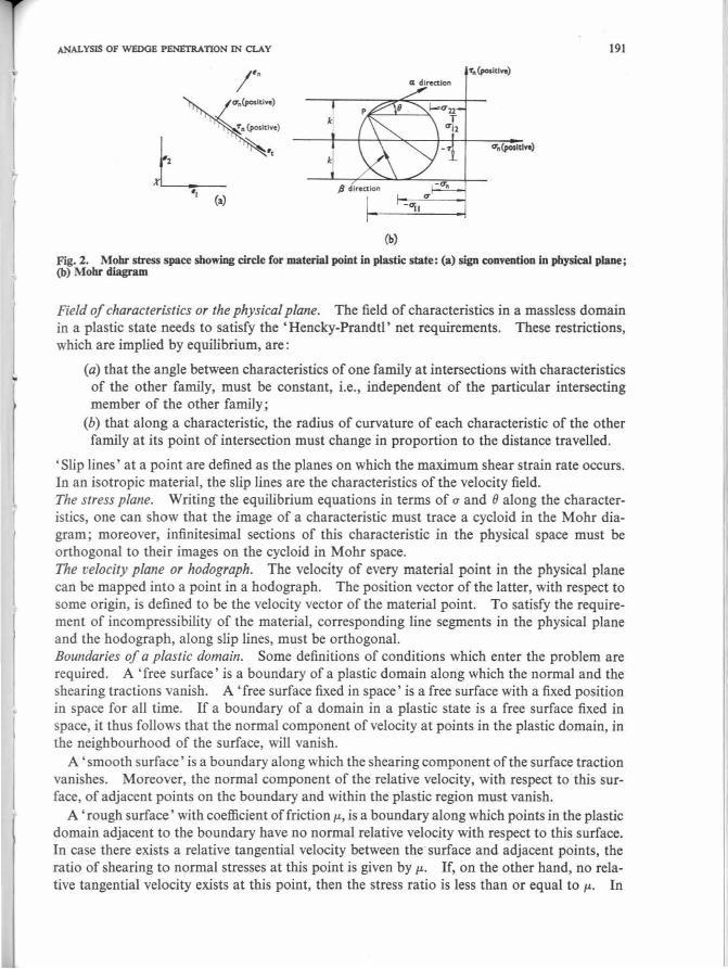
where all and a22 are the normal components of the stress tensor in the right-handed orthogonal Cartesian frame X. Unless otherwise mentioned X will be taken as in Fig. 2(a); a12 is the shearing component of the stress tensor in X; k is a material constant, = Y/2 for a Tresca material and = Y/v'(3) for a Von Mises material, where Y is the major principal stress at yield in simple axial extension or compression, i.e. the unconfined compressive yield stress. Equation (I) can be represented in a Mohr diagram (Fig. 2(b)) where the radius of the circle, describing the state of stress at the material point, has a value equal to k, which is conventionally called the cohesion or apparent cohesion of a clay. Material points in a 'rigid' or unyielding state have corresponding Mohr circles with radii less thank. Referring to Fig. 2,
a is the compressive hydrostatic stress at the point. an is the normal stress on a plane with outward normal en, taken to be positive when
tensile. rn is the shearing stress on the plane with outward normal en taken to be positive if it acts in the direction of et, "
where et, en form a right-handed orthogonal system.
The pole P is the point on the circle through which a straight line drawn parallel to et will intersect the circle at a point with co-ordinates equal to the stresses acting on a plane whose normal is en. The a and f3 directions are the directions of the planes on which maximum shearing stresses occur at the material point and thus form a right-handed orthogonal frame (in that order). The a line makes an angle 6 with the horizontal, being measured counterclockwise. The principal stress directions thus make angles of 45° ± 6 with the horizontal. In a yielding domain two sets of curves will be formed by lines parallel to a and f3 directions; they will be called the 'a family' and the '{3 family' respectively.
It is thus clear that if a point in the material is at a plastic state, the state of stress at this point is fully determined, given the position of the pole P. In this sense the stress plane, or Mohr diagram, may be considered as a mapping of the stress state at every point in the physical plane onto its corresponding pole location in the Mohr diagram. Thus the stress field in a plastic domain is described.
The conjugate problem Since only massless materials are considered, the problem of a rigid indenter moving in a
rigid plastic material with a constant velocity + U (to the right) is statically identical to the one in which the material is moving with a velocity - U (to the left) with respect to a.fixed indenter. The latter case, which is equivalent to taking the co-ordinate axes fixed to the indenter, will be referred to as the conjugate problem. The kinematics of a conjugate problem are such that its velocity field is equal to the velocity field of the initial problem superimposed on a constant field of magnitude - U.
Field equations, characteristics and slip lines Substitution from equation (I) into the equilibrium equations to eliminate derivatives of a12
gives a quasi-linear system of hyperbolic equations in all and u22. Using the graphical method of solution developed by Prager (I 959), the following three diagrams for each problem are needed.
..
ANALYSIS OF W£DGE PENETRATION IN CLAY 191
'f0 (posltin) Cl di,..,ctlon
le
L ~I
(a)
(b)
Fig. 2. Mohr stress space showing circle for material point in plastic state: (a) sign convention in physical plane; (b) Mohr diagram
Field of characteristics or the physical plane. The field of characteristics in a massless domain in a plastic state needs to satisfy the 'Hencky-Prandtl' net requirements. These restrictions, which are implied by equilibrium, are:
(a) that the angle between characteristics of one family at intersections with characteristics of the other family, must be constant, i.e., independent of the particular intersecting member of the other family;
(b) that along a characteristic, the radius of curvature of each characteristic of the other family at its point of intersection must change in proportion to the distance travelled.
'Slip lines' at a point are defined as the planes on which the maximum shear strain rate occurs. In an isotropic material, the slip lines are the characteristics of the velocity field. The stress plane. Writing the equilibrium equations in terms of a and 8 along the characteristics, one can show that the image of a characteristic must trace a cycloid in the Mohr diagram; moreover, infinitesimal sections of this characteristic in the physical space must be orthogonal to their images on the cycloid in Mohr space. The velocity plane or hodograph. The velocity of every material point in the physical plane can be mapped into a point in a hodograph. The position vector of the latter, with respect to some origin, is defined to be the velocity vector of the material point. To satisfy the requirement of incompressibility of the material, corresponding line segments in the physical plane and the hodograph, along slip lines, must be orthogonal. Boundaries of a plastic domain. Some definitions of conditions which enter the problem are required. A 'free surface' is a boundary of a plastic domain along which the normal and the shearing tractions vanish. A 'free surface fixed in space' is a free surface with a fixed position in space for all time. If a boundary of a domain in a plastic state is a free surface fixed in space, it thus follows that the normal component of velocity at points in the plastic domain, in the neighbourhood of the surface, will vanish.
A' smooth surface' is a boundary along which the shearing component of the surface traction vanishes. Moreover, the normal component of the relative velocity, with respect to this surface, of adjacent points on the boundary and within the plastic region must vanish.
A 'rough surface' with coefficient of frictionµ., is a boundary along which points in the plastic domain adjacent to the boundary have no normal relative velocity with respect to this surface. In case there exists a relative tangential velocity between the surface and adjacent points, the ratio of shearing to normal stresses at this point is given by µ.. If, on the other hand, no relative tangential velocity exists at this point, then the stress ratio is less than or equal to µ.. In
192 M, M. BAUGH AND R. F. SC0rr
much of the soil mechanics literature (Meyerhof, 1955; Schmertmann, 1967; Terzaghi, 1943) the conditions attending a rough surface have not been clearly established. Interface adhesion is neglected in this analysis. However, rough wedge solutions obtained subsequently still hold if adhesion is present.
From the previous definitions, it is clear that:
(a) for free and smooth surfaces, the slip lines at a point on the surface make an angle equal to ± TT/4 with the normal to the surface;
(b) for rough surfaces, there do not exist the perfectly rough or imperfectly rough surfaces which are often mentioned in the literature (Meyerhof, 1951, 1961), i.e., there exists one degree of roughness in the present case of clay, which is completely defined by specifying the parameter µ. which is a property of the two bodies in contact (solid friction); on the other hand the definition, being only applicable to points adjacent to the boundary, does not rule out the possibility of having any permissible velocity field within the plastic domain which may or may not have velocity discontinuities.
As an example, consider the rough surface I' with coefficient of friction µ. shown in Fig. 3. Let I' be fixed in space and the plastic material below it occupy regions Di and D2 • Let Di and D2 be separated by a characteristic £ which is taken, for simplicity, to be a straight line. Suppose that a permissible plastic state exists in Di and D2 , such that at any arbitrary point A on I' the ratio of tangential to normal stresses does not exceed µ.. It is clear that along I' the definition of a rough surface is satisfied if Di is fixed in space, while D2 may or may not be moving (e.g. parallel to £as a rigid body). (In fact, Di may be in a rigid state and the same mode of deformation would still occur. However such generalizations will not be needed herein.)
Steady state, assumed steady free surfaces, and uniqueness of solutions Along the front part of the wedge ABC in Fig. l(b), surface boundary conditions can be
defined either to be smooth or rough according to the problem considered. On the other hand, the shape of the boundary behind the wedge ADC is as yet unknown. However, the steady state condition implies that, in the conjugate problem, where soil is moving with respect to a fixed wedge, surfaces AD and CD are 'free surfaces fixed in space'.
In accordance with the general technique of solution using the method of characteristics, the shape of the plastic zone has to be assumed before the field equations are checked. Since surfaces AD and CD in Fig. l(b) are boundaries of the plastic domain, their configuration has to be assumed first. Uniqueness is therefore very difficult to prove in view of the arbitrariness in the assumed form of these surfaces. However, if motion is begun with these surfaces having the shape proposed below, uniqueness is guaranteed (Hill, 1950). It must also be pointed out that no more than one shape of these surfaces could be obtained for each problem.
EXACT SOLUTIONS
Smooth wedge Consider the steady state motion of a rigid smooth wedge in a rigid perfectly plastic infinite
medium (Fig. 4). The wedge angle 2& can take any value between zero and 7T, Along the front part of the wedge, AB and BC, the boundaries are well defined as smooth and rigid. Behind the wedge a gap or separation zone is assumed to exist and to have the geometry shown in Fig. 4, where AD and CD are straight and the angles ADE and CDE are equal to &. This geometry of the free surfaces AD and CD will be shown to produce a permissible steady state condition.
..

ANALYSIS OF WEDGE PENETRATION IN CLAY 193
Fig. 3. Example of permissible velocity field solution in vicinity of rough surface r
B
Physlal plane for :a smooth wedse
Fig. 4. Physical plane showing field of characteristics for steady state motion of rigid symmetric smooth wedge in rigid perfectly plastic infinite medium
... k
3'
k k(.,,.11 -.- 28) I k(1r t2 ~ 28l. i- k _
p .,- lk('ll'/l + l 8-.- I) • I Fig. 5. Stress plane for smooth wedge

194 M. M. BAUGH AND R. F. SCOlT
I ",I "'
Fig. 6. Hodograpb for smooth wedge
The physical plane is shown in Fig. 4 and is symmetrical about DB. Considering only the symmetrical half below the plane DB, the domain in a plastic state occupies three zones:
Zone I : determined by the triangle ADF in which both families of characteristics are straight and the distance AD=L;
Zone II: determined by the circular fan FAG in which the a characteristics are straight and the fJ lines consist of circular arcs;
Zone III: determined by the triangle ABG in which both families are straight and the distance AB=L.
This field satisfies the ' Hencky-Prandtl' net requirements and is thus permissible. The stress plane is shown in Fig. 5. The upper diagram maps the upper half of the physical
plane (above DB) and the lower diagram maps the lower half. Considering the latter, Zones I and III map into their corresponding image points I' and III' . In Zone II, since the radial a
lines are straight, the image of each is a point; the fJ lines are mapped into the cycloid shown in Fig. 5, which clearly satisfies the orthogonality requirement. Further, for values of {} between zero and 7r/4, this stress field can be shown (Hill, 1954) to produce no yielding at any point in the rigid region outside the plastic domain, and is therefore acceptable.
From Fig. 5, the normal stress p at the interface is given by
p = k(7T+4t>+2), where 0 < {} < TT/2 (2)
Recalling that for a smooth wedge the shearing stresses vanish at the interface the resultant force H per unit length of the wedge perpendicular to the figure may be determined by integrating the interface stresses given by equation (2), to give
H = 2Lk sin t> [TT +4t?+2], where 0 < t? < TT/2 (3)
The velocity of the soil is given by the hodograph in Fig. 6. The rigid part of the infinite medium outside the plastic domain, which is fixed in space, is mapped into the origin 0. The rigid wedge is mapped into point W at a distance U to the right of 0. In Zones I and III both families of characteristics are straight, and these zones move as rigid bodies with their corresponding images at the two points r and nr whose location is still unknown.

. I
r
ANALYSIS OF WEDGE Pl!NF:I'RATION IN CLAY 195
A lr&•P
so 0-20
'40 0-16 ';:0
:.< • .2 t:
" :E ... 'O e JO 0-11 ~
~ y ( e ) • "'sin (sin e / / l } ~ w "r,( 9 ) - lt[ lwll + I + l ( 8 + 'Y )) 8 .; o-oe ~ 'O lO
E w c ... 0 f Vi
10 Y(9}
o-04
0 10 10 lO '40
H1lf •nil• of wed&• 8 : des.
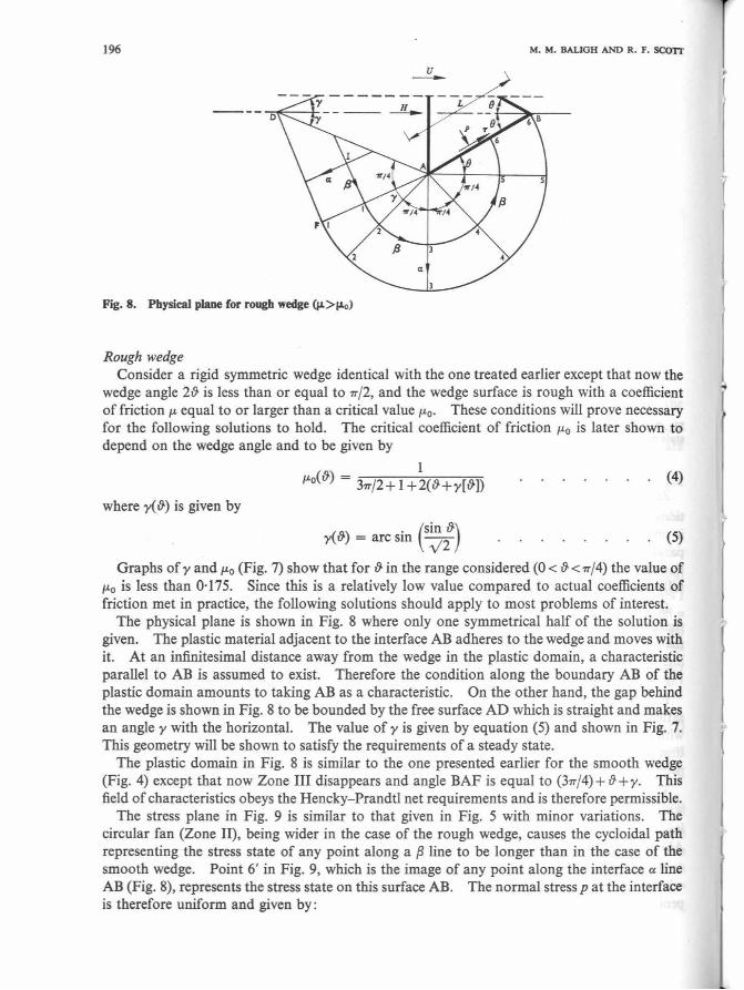
Fig. 7. Slope of the free surface behind wedge and minimum coefficient of friction for rough rigid wedge in steady state motion in rigid plastic space
Zone III moves parallel to BG in Fig. 4 and Zone I moves parallel to FD, so that the direc
tions of or and OIIr must be at angles ± (TT/4+ {))with the horizontal. Since interface AB is smooth, a jump between the wedge velocity and the velocity of adjacent points in Zone III, parallel to AB, is permissible. The jump J is assumed to exist, and thus point III* lies on a line through W making an angle {}with the horizontal. The locations of points I* and III* are fully determined.
In Zone II the radial ex lines are straight. Since the region outside the plastic domain is rigid, the velocity at any point in Zone II can only be in a tangential direction, i.e. parallel to the f3 line through the point. Now applying the orthogonality condition, the image of each ex
line is a point and the image of any f3 line such as 54321 in Fig. 4 is the curve 5•4•3•2•1 • in Fig. 6, which must be an arc of a circle centered at 0.
From the previous treatment, the proposed stress and velocity fields are instantaneously satisfied. It remains, however, to prove continuity in the sense that to an observer moving with the wedge this velocity field yields a solution that will maintain the geometry of deformation unaltered at any time. For this it is necessary and sufficient to show that in the conjugate problem, the surface AD (Fig. 4) is a free surface fixed in space.
The conjugate problem is, by definition, the same as the original problem treated above but with the origin of the hodograph at Winstead of at 0 . From the symmetry of the hodograph, it is clear that WI* makes an angle {} with the horizontal. This means that points adjacent to AD move parallel to it and the surface is a free surface fixed in space as required.
Now that the problem is solved, distortions in the plastic region can be computed. This will be treated later in the case of a rough wedge which should prove more useful for practical problems.
196 M. M. BAUGH AND R. F. SCX>n
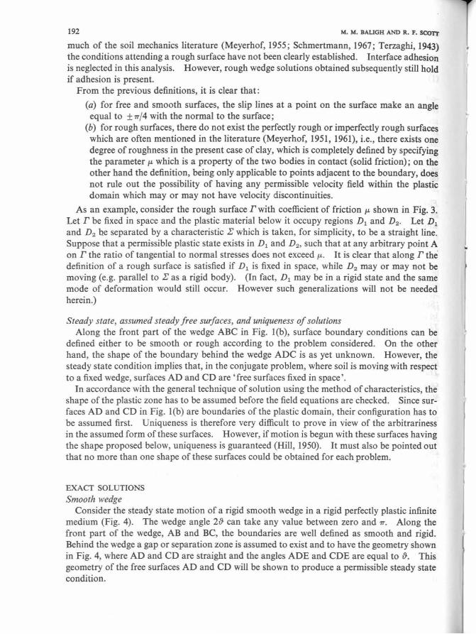
Fig. 8. Physical plane for rough wedge (µ>f.Lo)
Rough wedge Consider a rigid symmetric wedge identical with the one treated earlier except that now the
wedge angle 2{} is less than or equal to TT/2, and the wedge surface is rough with a coefficient of friction µ. equal to or larger than a critical value µ.0 • These conditions will prove necessary for the following solutions to hold. The critical coefficient of friction µ.0 is later shown to depend on the wedge angle and to be given by
l JLo({}) = 3TT/2+ I +2({}+y[&]) (4)
where y( {}) is given by
. (sin {}) y( {}) = arc sm v'2 (5)
Graphs of 'Y and µ.0 (Fig. 7) show that for {}in the range considered (0 < {} < TT/4) the value of µ.0 is less than 0· 175. Since this is a relatively low value compared to actual coefficients of friction met in practice, the following solutions should apply to most problems of interest.
The physical plane is shown in Fig. 8 where only one symmetrical half of the solution is given. The plastic material adjacent to the interface AB adheres to the wedge and moves with it. At an infinitesimal distance away from the wedge in the plastic domain, a characteristic parallel to AB is assumed to exist. Therefore the condition along the boundary AB of the plastic domain amounts to taking AB as a characteristic. On the other hand, the gap behind the wedge is shown in Fig. 8 to be bounded by the free surface AD which is straight and makes an angle 'Y with the horizontal. The value of 'Y is given by equation (5) and shown in Fig. 7. This geometry will be shown to satisfy the requirements of a steady state.
The plastic domain in Fig. 8 is similar to the one presented earlier for the smooth wedge (Fig. 4) except that now Zone III disappears and angle BAF is equal to (377/4) + {} + 'Y· This field of characteristics obeys the Hencky-Prandtl net requirements and is therefore permissible.
The stress plane in Fig. 9 is similar to that given in Fig. 5 with minor variations. The circular fan (Zone II), being wider in the case of the rough wedge, causes the cycloidal path representing the stress state of any point along a p line to be longer than in the case of the smooth wedge. Point 6' in Fig. 9, which is the image of any point along the interface a line AB (Fig. 8), represents the stress state on this surface AB. The normal stress pat the interface is therefore uniform and given by:
'
l

ANALYSIS OF WEDGE PBNl!TRATION IN CLAY 197
k
p - k [31rt2 + I + 2 ( 0 +'Y)J
Fig. 9. Stress plane for rough wedge
u
S"
Fig. 10. Hodograph for rough wedge
p = k [3; + l +2(8-+y)] (6)
and the shearing stress -r at the interface is also uniform and given by
-r=k m From equations (6) and (7) the ratio of -r top is equal to µ.0 as given by equation (4). When
the actual coefficient of friction at the interface µ. is larger than µ.0 , the assumption that the plastic material adheres to the wedge is therefore justified and the solution is applicable. However, ifµ. is less than µ.0, the solution clearly imposes shearing stresses at the interface that are higher than the ones allowed ; alternatively AB in Fig. 8 cannot be taken as a characteristic and the present solution is no longer applicable. In such circumstances (0 < µ. < µ.0) , a treatment similar to the one presented by Grunzweig (1952) could conceivably be performed and would be expected to give a different solution for each value ofµ. . Furthermore, when 8' lies in the range 0 < & ~ TT/4 the stress field could be extended in the rigid part outside the plastic zone without violating the yield condition. This limits the rough wedge solution to sharp wedges with apex angles less than or equal to 90°, while the smooth wedge solution was applicable to blunt as well as sharp wedges.
Integrating the interface tractions given by equations (6) and (7), and taking the horizontal components, the total horizontal force H per unit length of the wedge required to cause the motion is given by:

198 M. M. BAUGH AND R. F. scon
H = 2Lk{[3; + l +2(&+y)J sin &+cos&} (8)
The velocity field in the soil is given by the hodograph in Fig. 10. The origin 0 is the image of the static rigid material outside the plastic domain. The rigid wedge is mapped into W which lies at a distance U to the right of 0. A jump J between the plastic material sticking to the wedge and the material at an infinitesimal distance from AB is permissible and is assumed to exist. It thus follows that point 6• (Fig. JO) which is the image of the point 6 in the plastic zone (Fig. 8) just below AB, lies on a line through W making an angle & to the horizontal.
Furthermore, as the component of velocity at 6 along the a line is zero, the line 06 .. must be at an angle & to the vertical, i.e. is perpendicular to W6•. The location of 6 .. is now deter
mined and 06 .. = U sin &.
Since the curve 6 .. 5 .. 4 .. 3 .. 2• 1 .. (the image of any f3 line 654321) is a circular arc centered at 0,
and knowing that the velocity of Zone I must be at an angle (45° +y) to the horizontal, then Or is equal to U sin {} and is at an angle ( 45° + y) to the horizontal. If the symbol ji is given to the angle OWi*, an argument similar to that presented earlier for the smooth wedge will show that, to satisfy the steady state condition, it is necessary to prove that ji = y. This result becomes immediately obvious when equation (5) is used with the triangle OW!* in the hodograph in which
U U sin{} sin ("/4+y-ji) sm ji
Now that the solution is complete, the distortion of an initially square grid in the region which will deform plastically can be obtained. This could either be done analytically or graphically. The graphical method using the hodograph for the conjugate problem proved sufficiently accurate and much simpler than the analytic technique when tried on related problems (Baligh, 1972), and will be followed here. Knowing the velocity vector at points in the deformable medium as they move past the wedge, the stream lines are first obtained. Next the distortion of originally vertical lines is determined by following every point along a stream line as it approaches the wedge; the known magnitude of the velocity makes it possible to determine the location of the deformed vertical lines through a step-by-step procedure. Finally, and as a check on both the hodograph and the accuracy of the distortion computation, the area inside each quadrilateral should remain the same; this is the expression of the incompressibility of the material.
The results of these operations are shown by the solid lines in Figs 11- 13 for rough wedges with &= 10°, 30° and 45° respectively. In these figures dotted lines define the plastic domain. The accuracy of the deformed grid depends, of course, on the graphical integration technique employed; it is sufficiently accurate for engineering purposes. In any one of the three figures:
(a) the distortions occur only within the plastic domain which extends a distance L on either side of the wedges; this is due to the assumption that the material is rigid at stresses below yield;
(b) the slope of the stream lines undergoes a discontinuity at the boundary between the rigid and the plastic domains, this occurs because of the jump in velocity that exists across this boundary ;
(c) horizontal lines ahead of the wedge remain horizontal and at the same level after passing through the plastic domain; this is a consequence of the incompressibility of the material;
" r

ANALYSIS OF WEDGE PENETRATION IN CLAY 199
(d) the distorted vertical lines have a slope that changes from negative to positive as they approach the centre line of the wedge; physically this means that some material is pushed backwards as the wedge is moved forward, or that in the conjugate problem some points in the plastic domain have a velocity higher than points in the far field; this phenomenon arises because the material is incompressible and the plastic zone is finite in width.
Fig. 11. Distortion of square grid for 6=10°
Fig. U. Distortion of square grid for 6=30°
Fig. 13. Distortion of square grid for 6 =45°
u --
200 M. M. BAUGH AND R. F. SC0Tr
z(axls)
+ +:t++:·: + .. '
++•:+• + +. + + t + ++ t + ... + +,' .................... + +-+ + + t'
'+ -+•+ ...... • ... .. 1 + ' + + , '+.. + + t + ,,+~
+ '+....... .......... + + +--+-- --+_ .... - +
+ + Circle I: + + +
+
+
+ +
400mm
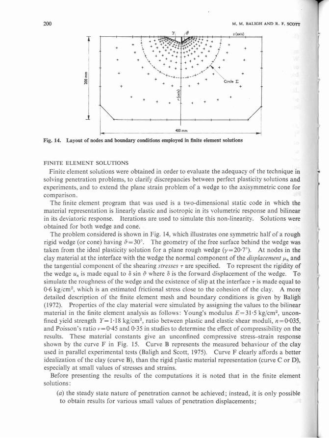
Fig. 14. Layout of nodes and boundary conditions employed in finite element solutions
FINITE ELEMENT SOLUTIONS
Finite element solutions were obtained in order to evaluate the adequacy of the technique in solving penetration problems, to clarify discrepancies between perfect plasticity solutions and experiments, and to extend the plane strain problem of a wedge to the axisymmetric cone for comparison.
The finite element program that was used is a two-dimensional static code in which the material representation is linearly elastic and isotropic in its volumetric response and bilinear in its deviatoric response. Iterations are used to simulate this non-linearity. Solutions were obtained for both wedge and cone.
The problem considered is shown in Fig. 14, which illustrates one symmetric half of a rough rigid wedge (or cone) having {}= 30°. The geometry of the free surface behind the wedge was taken from the ideal plasticity solution for a plane rough wedge (y=20·7°). At nodes in the clay material at the interface with the wedge the normal component of the displacement µ.n and the tangential component of the shearing stresses-rare specified. To represent the rigidity of the wedge Un is made equal to 8 sin {}where 8 is the forward displacement of the wedge. To simulate the roughness of the wedge and the existence of slip at the interface -r is made equal to 0·6 kg/cm2
, which is an estimated frictional stress close to the cohesion of the clay. A more detailed description of the finite element mesh and boundary conditions is given by BaJigh (1972). Properties of the clay material were simulated by assigning the values to the bilinear material in the finite element analysis as follows: Young's modulus E= 31 ·5 kg/cm2
, unconfined yield strength Y = l · 18 kg/cm2
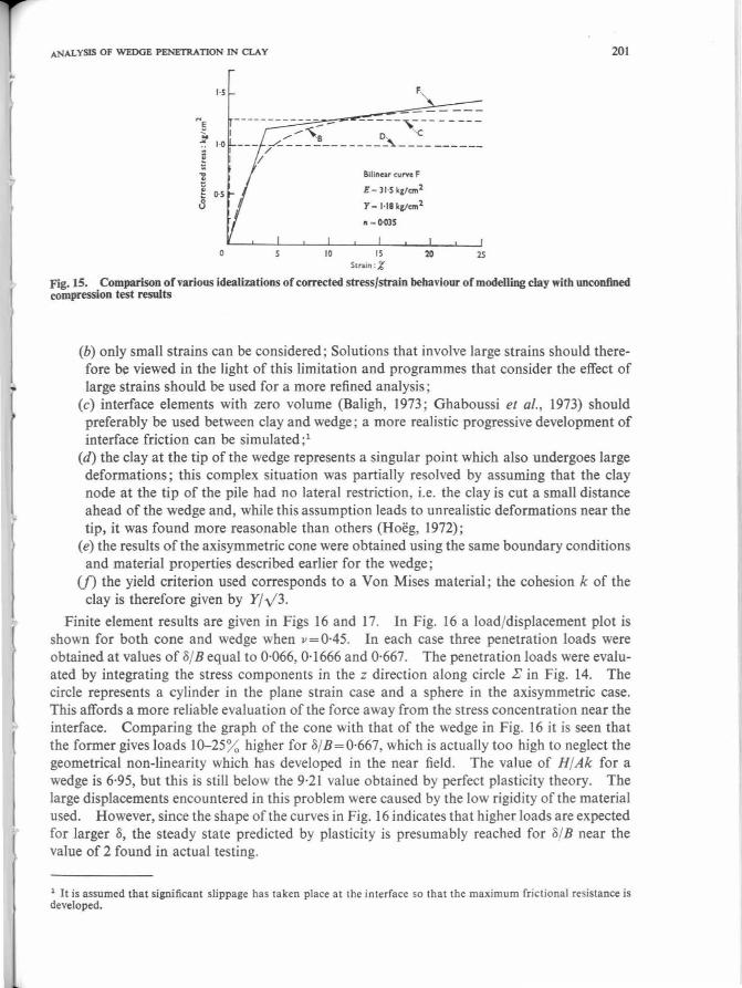
, ratio between plastic and elastic shear moduli, n = 0·035, and Poisson's ratio v=0·45 and 0·35 in studies to determine the effect of compressibility on the results. These material constants give an unconfined compressive stress-strain response shown by the curve F in Fig. 15. Curve B represents the measured behaviour of the clay used in parallel experimental tests (Baligh and Scott, 1975). Curve F clearly affords a better idealization of the clay (curve B), than the rigid plastic material representation (curve C or D), especially at small values of stresses and strains.
Before presenting the results of the computations it is noted that in the finite element solutions:
(a) the steady state nature of penetration cannot be achieved; instead, it is only possible to obtain results for various small values of penetration displacements ;
t
l ANALYSIS OF WEDGE PENETRATION IN CLAY
NE Jt 1-0
~ ~ j 0-S
0
------------- - -----,--- - - ---....... '8 'c
--- /.../....~----------~---- ------/
10
Blline.u curve F
E - ll·S kilanl
Y- H8k£tcm2
~ -l>OlS
15 Strain :%
20 25
201
Fig. 15. Comparison of various idealizations of corrected stress/strain behaviour of modelling clay with unconfined compression test results
(b) only small strains can be considered; Solutions that involve large strains should therefore be viewed in the light of this limitation and programmes that consider the effect of large strains should be used for a more refined analysis;
(c) interface elements with zero volume (Baligh, 1973; Ghaboussi et al., 1973) should preferably be used between clay and wedge; a more realistic progressive development of interface friction can be simulated ;1
(d) the clay at the tip of the wedge represents a singular point which also undergoes large deformations; this complex situation was partially resolved by assuming that the clay node at the tip of the pile had no lateral restriction, i.e. the clay is cut a small distance ahead of the wedge and, while this assumption leads to unrealistic deformations near the tip, it was found more reasonable than others (Hoeg, 1972);
(e) the results of the axisymmetric cone were obtained using the same boundary conditions and material properties described earlier for the wedge;
(f) the yield criterion used corresponds to a Von Mises material; the cohesion k of the clay is therefore given by Y/ y3.
Finite element results are given in Figs 16 and 17. In Fig. 16 a load/displacement plot is shown for both cone and wedge when 11=0·45. In each case three penetration loads were obtained at values of o/B equal to 0·066, 0· 1666 and 0·667. The penetration loads were evaluated by integrating the stress components in the z direction along circle .E in Fig. 14. The circle represents a cylinder in the plane strain case and a sphere in the axisymmetric case. This affords a more reliable evaluation of the force away from the stress concentration near the interface. Comparing the graph of the cone with that of the wedge in Fig. 16 it is seen that the former gives loads 10-25% higher for S/B=0·667, which is actually too high to neglect the geometrical non-linearity which has developed in the near field. The value of H/Ak for a wedge is 6·95, but this is still below the 9·21 value obtained by perfect plasticity theory. The large displacements encountered in this problem were caused by the low rigidity of the material used. However, since the shape of the curves in Fig. 16 indicates that higher loads are expected for larger o, the steady state predicted by plasticity is presumably reached for o/B near the value of 2 found in actual testing.
1 It is assumed that significant slippage has taken place at the interface so that the maximum frictional resistance is developed.

202
10
0 1 02 03
&tB
k - Y!Jl
For cone : A - f B 2
For wed1e : A - B
OS 06
M. M. BAUGH AND R. F. SC0Tr
07
Fig. 16. Load/displacement relations obtained by finite element calculations for displacement of wedge with 6=30° in a bilinear material with properties: E=31 ·S kg/cm2
; Y=l ·18 kg/cm2; v=0·45; n=0·035
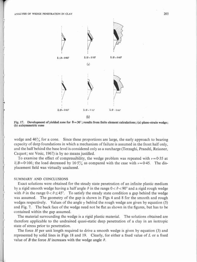
The development of the plastic zone as o/ B increases is shown in Fig. 17. The black region is where severe shearing takes place. In this zone the secant shear modulus is smaller than one fifth of the initial shear modulus. The shaded area is a transition zone between severe shearing and the elastic zone where yielding is not reached. The similarity and differences between the wedge and cone become clear when Figs 17(a) and (b) are compared. Moreover the yielded zones lie mainly ahead of the indenters and do not extend as far behind as perfect plasticity predicts. This phenomenon was also found in solving for the indentation of a halfspace by a smooth circular punch (Baligh, 1972) using the same finite element technique. Other investigators using different numerical procedures have reached similar results (e.g. Ellison et al. ( 1971) in their step-by-step finite element solutions for a pile with a flat tip).
The displacement field when o/ B = 0· 167 for both wedge and cone was also studied (Baligh, 1972). Comparing the results for the two cases, it was found that :
(a) the displacement patterns were similar; in the case of a cone, however, the displacements were generally smaller and, as expected, died off faster as the distance from the interface increased ; the deformation near the tip, in the case of a cone, simulated the indentation process better than the wedge;
(b) in both cases, the region ahead of the indenter was the roost heavily distorted ; displacements were detectable up to a distance of about 3B for a wedge and 2B for a cone (these distances vary of course with o/B);
(c) due to the elliptic character of the equations governing the finite element solutions, the displacement field for both the cone and the wedge is smoothly varied with no discontinuities in its gradient (this condition is found in actual testing and differs from the results of perfect-plasticity computations which assume the existence of a rigid domain);
(d) the displacement ahead of the indenters was mostly in the radial direction, which would therefore tend to justify recent approaches to the problem of the bearing capacity of deep foundations in which the penetration process is idealized by the expansion of a cavity under conditions of radial symmetry (Vesic, 1972) ; on the other hand, the displacement field behind the indenters was predominantly parallel to the motion, which does not agree with such an approach.
Other results of interest were that by computing the part of the load carried by the rear half of circle E, when o/B= 0·0667 (Fig. 14) it was found that it was 38% of the total load for a
ANALYSIS OF WEDGE PENETRATION IN CLAY 203
(a)
~ ~ '
S;B - ~7 o/ B- 1>167 S;B ~ o 667
(b)
Fig.17. Development of yielded zone for 6=30°; results from finite element calculations; (a) plane-strain wedge; (b) axisymmetric cone
wedge and 46% for a cone. Since these proportions are large, the early approach to bearing capacity of deep foundations in which a mechanism of failure is assumed in the front half only, and the half behind the base level is considered only as a surcharge (Terzaghi, Prandtl, Reissner, Caquot; see Vesic, 1967) is by no means justified.
To examine the effect of compressibility, the wedge problem was repeated with v=0·35 at o/B=O·I66; the load decreased by 16·5% as compared with the case with v=0·45. The displacement field was virtually unaltered.
SUMMARY AND CONCLUSIONS
Exact solutions were obtained for the steady state penetration of an infinite plastic medium by a rigid smooth wedge having a half angle {} in the range 0 < {} < 90° and a rigid rough wedge with {}in the range 0 < {}:::; 45°. To satisfy the steady state condition a gap behind the wedge was assumed. The geometry of the gap is shown in Figs 4 and 8 for the smooth and rough wedges respectively. Values of the angle y behind the rough wedge are given by equation (5) and Fig. 7. The back face of the wedge need not be flat as shown in the figures, but has to be contained within the gap assumed.
The material surrounding the wedge is a rigid plastic material. The solutions obtained are therefore applicable to the undrained quasi-static deep penetration of a clay in an isotropic state of stress prior to penetration.
The force H per unit length required to drive a smooth wedge is given by equation (3) and represented by solid lines in Figs 18 and 19. Clearly, for either a fixed value of Lor a fixed value of B the force H increases with the wedge angle {}.

204
H
20
16
g_
~cz :::? Rouzh wedce ,,.... ~,,,,. ,,,,..,,,.
/ /
/ /
10
/ /
/
20 )0
/ /
/
Smooth wedie
/ /
/
Smooth wedce H 2 I.le sin 8 , ,,. ~ 2 ~ ~ 8 J Rou1h wedce
M. M. BAUGH AND R. F. SC0Tr
H - 2I.lc /p,,.n - 1 + 2(8 + Y)) sln8 + cos8/
so 60 70 80 90
8 : d•&·
Fig. 18. Force required to produce steady state motion of rigid wedge in rigid perfectly plastic full space
Solutions for the rough wedge are valid so long as the interface friction coefficient is larger than a critical value µ.0 (given by equation (4)) which is relatively small. In most practical cases where the indenter surface is not treated with friction reducing agents, µ. is expected to exceed µ.0 and will therefore have no effect on the results .
The force H per unit length of the wedge required to drive a rough wedge is given by equation (8) and represented by the dotted lines in Figs 18 and 19. For a fixed length of side L with constant k, the value of H increases with &. However for a fixed width B the value of Hf Bk attains a minimum of 9· 194 at {} = 33·6°.
From Fig. 19 it can be seen that for sharp rough wedges the value of Hf Bk rises sharply as{} decreases. This is due to the substantial effect of the shearing stresses T along the faces of the wedge. As an example, when &=I 0 , the value of Hf Bk is 63·06, of which 91 % is due to T.
It is interesting to compare the results of the present solution, for small {}, with the indentation of a rigid plastic half space by a rigid rough wedge (Grunzweig et al., 1952). When the coefficient of interface friction µ. is larger than 0·39 (a condition frequently met in applications), both solutions hold and are thus comparable. The mechanism of failure is similar ; specifically the interface shearing stress T is equal to k (the cohesion of the clay) in both cases. For&= I 0 Grunzweig's solution gives a value of H f Bk which is lower than the present solution by less than 10%. Since the main difference between the two problems is in the location of the free surface, this result means that, for small {}, the geometry of the plastic region has only a small effect on the indentation force. Moreover, when Grunzweig's problem was checked experimentally (Hirst and Howse (1969)) his failure mechanism proved correct for small &. Other experiments with cones and pyramids (Atkins and Tabor, 1965; March, 1964) have shown similar results and proved the plane strain solution to be a good start in interpreting the more complicated case.
From Fig. 19 for rough wedges having {} between 15° and 45°, the value of H /Bk is bounded between 10·5 and 9· 194. In fact the same result would hold if the present solution was extended to &= 90°. Thus over a wide range of wedge angle the value of H /Bk changes only slightly (less than 15% ). Some previous observations in this regard (De Mello, 1969; Mensenbach, 1961) are :
(a) the value of Hf Bk for a wedge (where His the load per unit width) is roughly the same as for a cone when H is the total load and B is the projected area of the cone and this
r
I .. I
{
I

(
[
l
Fig. 19. Force required to produce steady state motion of rigid wedge in rigid perfectly plastic full space
value is about 9; this is one reason why the results of plane strain solutions can be used in connexion with the axisyrometric point resistance of piles (Berezantzev, 1965; Meyerhof, 1951; Skempton, 1951; Terzaghi, 1943);
(b) the effect of{} on Hf Bk for a cone is negligibly small for a range of practical values of {} (say 15° < {} < 90°), which confirms the use of the cone penetrometer test ( {} = 30°) to estimate pile resistance where in piles 60° < {} < 90° (see DeBeer, 1963).
Deformations in the soil due to rough wedge penetration were obtained and are shown in Figs 11-13 for {}= 10°, 30° and 45° respectively. Distortions occur in the plastic zone which extends a distance L on either side of the wedge and are generally too large to allow the use of infinitesimal strain theories in the analysis of penetration problems. Comparing the three figures to see the effect of wedge angle 2{} on the distorted mesh, for a constant wedge thickness B:
(a) the plastic zone decreases in size as {} increases; (b) the curvature of the stream lines increases as {} increases; (c) the slope of the distorted vertical lines becomes larger as {}increases.
Points (a) and (b) mean that for a constant indentation velocity Uthe rate of straining and the intensity of straining become larger as {}increases. These results are important if the response of the clay is rate dependent or if its behaviour is either strain hardening or strain softening. Different values of penetration resistance obtained in one material with these kinds of behaviour for different penetrometer angles can then be understood.
When an attempt was made to start with the deformation patterns in Fig. 11 and then to derive the strains with sufficient accuracy to compute stress fields, very limited success was achieved. This operation is sometimes performed when experimental deformations are recorded and later used to compute strain and stress distributions. If complications caused by the actual material response are also included, this technique should be viewed with caution. A crucial factor in this process is the accuracy in differentiating the displacement field. A graphical method can be calibrated by performing the same operations on the present solutions.

206 M. M. BAUGH AND R. F. 5C0Tr
Solutions presented for rough wedges were not proven unique and do not include blunt wedges; hence failure modes including a dead zone ahead of the wedge and moving with it are likely to occur when {} is large. The presence of a dead zone was experimentally observed in the indentation of a half space by a rigid blunt wedge (Johnson, 1970).
From the symmetry of the problem, a dead zone, if present, will also be symmetrical. A first attempt to incorporate it in the solution is to assume that it has straight boundaries, in which case the solution is readily available and is given by the rough wedge results. In this case, however, {}represents the half angle of the dead zone. Suppose that the criterion governing the motion of wedges is that the energy dissipated in the indentation process is a minimum. The previously mentioned dead zones develop if necessary in order to meet this condition. Assuming that dead zones have straight boundaries, a rough wedge with & up to 33·6° will thus develop no dead zones and require pushing with the value of H given by curve ab in Fig. 19. However, when & exceeds 33·6° a dead zone develops with a half angle equal to 33·6°. The result of this is a constant value of H equal to 9· 194 Bk (the straight horizontal line bd in Fig. 19). On the other hand, a smooth wedge will develop no dead zones up to t>= 58·05° and the value of H for this angle is given by the straight line ef in Fig. 19. When & exceeds 58·05°, the theoretical resistance of the smooth wedge would exceed that of the rough wedge. This would not occur, so that the distinction between smooth and rough surfaces vanishes and a dead zone develops with a half angle equal to 33·6°. The result is a constant value of H for both smooth and rough blunt wedges, equal to 9· 194 Bk (the straight horizontal line fd in Fig. 19).
The above speculations with respect to the dead zones ahead of the wedges require either that they be in a plastic state but moving with a constant velocity U or that the yield criterion is not reached anywhere in them. A theoretical study of the existence and geometry of the dead zones is difficult to conceive and it is necessary to rely on experiments (Baligh and Scott, 1975). The prime target of those experiments will be to determine the pattern of deformation as a function of{} because the measurement of indentation forces alone is expected to be inconclusive in view of their weak dependence on &.
Finite element results showed that a strong similarity exists for cone and wedge solutions. The resistance of a cone is indicated to be 10-25% higher than that of a wedge. In view of the flexibility of the finite element technique and its potential for extending present concepts to more practical problems, the following difficulties of large deformations, material and geometrical nonlinearities, the singularity at the penetrometer tip and the soil/penetrometer interface deserve special consideration and need to be represented in finite element models.
The effect of internal friction in the plastic material was not included in this analysis and is currently under investigation to develop a better understanding of penetration in sand.
REFERENCES
Abdul-Baki, A. & Lewis, A. B. (1970). Bearing capacity of foundations on sand. J. Soil Mechs Founds Div., ASCE 96, SM2, March, 545- 559.
Atkins, A.G. & Tabor, D. (1965). Plastic indentation in metals with cones. Jn/ Mech. Phys. Solids 13, 149. Baligh, M. (1972). Applications of plasticity theory to selected problems in soil mechanics. Soil Mechanics
Laboratory Report, California Institute of Technology, Pasadena, California. Baligh (1973). Numerical study of uniaxial and triaxial rock compression tests. Report No. SSS-R-73-1658,
Systems, Science and Software, Inc., La Jolla, California, May. Baligh, M. & Scott, R. F. (1975). Quasi-static deep penetration in clays. J. Geotech. Eng. Div., ASCE, 101,
GTll, Nov., 1119-1133. Balla, A. (1962). Bearing capacity of foundations. J. Soil Mechs Founds Div., ASCE 88, SM5, Oct., l 3-34. Berezantev, V. G. (1965). Design of deep foundations. Proc. 6th Int. Con/ Soil Mechs Found. Engng 2, 234. Bishop, R. F., Hill, R. & Mott, N. F. (1945). The theory of indentation and hardness tests. Proc. Phy. Soc.
57, 147.
..
r
(
f
(

..
l
[
ANALYSIS OF WEDGE PENETRATION IN CLAY 207
Brinch-Hansen, J. (1961). A general formula for bearing capacity. Bulletin No. I I, Danish Geotechnical Institute, Copenhagen, 38-46.
Broms, B. B. (1964). Lateral resistance of piles in cohesive soils. J. Soil Mechs Founds Div. ASCE90, SM2, March, 27.
Chadwick, P. (1959). The quasi-static expansion of a spherical cavity in metals and ideal soils. Quart. J. Mechs Appl. Math. 12, l, 52
Cox, A. D., Eason, G. & Hopkins, H. G. (1961). Axially symmetric plastic deformations in soils. Trans. Roy. Soc. 254A.
Cox, A. D . (1962). Axially symmetric plastic deformation in soils-II, indentation of ponderable soils. Int. J. Mech. Sci. 4, 371.
DeBeer, E. E. (1963). The scale effect in the transposition of the results of deep sounding tests on the ultimate bearing capacity of piles and caisson foundations, Geotechnique 13, No. I , 39.
DeBeer, E. E. (1965). Bearing capacity and settlement of shallow foundations on sand. Proc. Symp. Bearing capacity and settlement of foundations, Duke University, 15-34.
DeBeer, E. E. (1970). Experimental determination of the shape factors and the bearing capacity factors of sand. Geotechnique 20, No. 4, 387-411.
De Mello, V. (1969). Foundations of buildings in clay. State-of-the-art Volume, 7th Int. Conf Soil Mechs Foundn Engng, Mexico, 49.
Dugdale, D . S. (1953). Wedge indentation experiments with cold worked metals. J. Mech. Phys. Solids 2, 14. Dugdale, D .S. (1954). Cone indentation experiments. J. Mech. Phys. Solids 2, 265. Dugdale, D. S. (1955). Experiments with pyramidal indenters. J. Mech. Phys. Solids 3, 197. Durgunoglu, H. T. & Mitchell, J. K . (1973). Static penetration resistance of soils. Space Sciences Laboratory
Report, Series 14, Issue 24, Geotechnical Engineering Department, University of California, Berkeley. Ellison, P. D ., D 'Appolonia, E. & Thiers, G. R. (1971). Load deformation mechanism for bored piles. J. Soil
Mech. Found. Div., ASCE 97, SM4, 661. Gibson, R. E. (1950). Discussion on Wilson, G; Bearing capacity of screw piles and screw crete cylinders.
J. Inst. Civ. Engrs 34, 382. Gorbunov-Possadov, M. I. (1965). Calculations for the stability of sand bed by a solution combining the
theories of elasticity and plasticity. Proc. 6th Int. Conf Soil Mechs Found. Engng 2, 51-55 Graham, J. (1968). Plastic failure in cohesionless soils. Geotechnique 18, No. 3, 301-316. Grunzweig, J., Longman, I. M. & Petch, N. J. (1952). Calculations and measurements on wedge-indentation.
J. Mech. Phys. Solids 2, 81. Hansen, B. & Christensen, N. H. (1968). D iscussion on Larkin, L. A.: Theoretical bearing capacity of very
shaUow footings. J. Soil Mechs Founds Div., ASCE 95, SM6, Nov., 1568-1572. Hill, R. (1950). The mathematical theory of plasticity. Oxford, University Press, 254. Hill, R., Lee, E. H. & Tupper, S. J. (1947). The theory of wedge indentation of ductile materials. Proc. Roy.
Soc., Series A 188, 273. Hill, R . (1954). On the limits set by plastic yielding to the intensity of singularities of stress. J. Mech. Phys.
Solids 2, 278. Hirst, W. & Howse, M. G. (1969). The indentation of materials by wedges. Proc. Roy. Soc., Series A 311, 429. Hoeg, K. (1972). Finite element analysis of strain-softening clays. J. Soil Mech. Found. Div., ASCE 98,
SMI , Jan. 27. Hu, G . (1970). Discussion on Adbul-Baki and Lewis: Bearing capacity of foundations on sand. J. Soil
Mechs Foundn Div., ASCE 96, SM6, Nov., 2151. Hvorslev, M. J. (1970). The basic sinkage equations and bearing capacity theories. Technical Report M-70-1,
US Army Engineering Waterways Experiment Station, Vicksburg, Mississippi. Johnson, K. L. (1970). The correlation of indentation experiments. J. Mech. Phys. Solids 18, 115-126. Jumikis, A . R . (1961). The shape of rupture surface in dry sand. Proc. 5th Int. Conf Soil Mechs Foundn
Engng 1, 693; 3, 227. Larkin, L. A. (1968). Theoretical bearing capacity of very shalJow footings. J. Soil Mechs Foundn Div ..
ASCE94, SM6, ov., 1347-1357. Lockett, F. J. (1963). Indentation of a rigid/plastic material by a conical indenter. J. Mech. Phys. Solids 11,
345- 355. Lundgren, H. & Mortensen, K. (1953). Determination by the theory of plasticity of the bearing capacity of
continuous footings on sand. Proc. 3rd Inter. Conf Soil Mechs Foundn Engng 1, 409. March, D . M. (1964). Plastic flow in glass. Proc. Roy. Soc., Series A 279, 420. Mensenbach, E. (1961). The determination of the permissible point load of piles by means of static penetration
tests. Proc. 5th Int. Conf Soil Mechs Foundn Engng 2, 99. Meyerhof, G . G. (1951). The ultimate bearing capacity of foundations. Geotechnique 2, No. 4, 301-332. Meyerhof, G. G. (1955). Influence of roughness of base and ground water conditions on the ultimate bearing
capacity of foundations. Gclotechnique 5, No. 3, 227-242. Meyerhof, G. G. (1961). The ultimate bearing capacity of wedge-shaped foundations. Proc. 5th Int. Con!
Soil Mechs Foundn Engng 2, 105-109.

208 M. M. BAUGH AND R. F. SCOTT
Meyerhof, G. G . (1961). Discussion on shallow foundations: influence of the dimensions and the shape of the foundations. Proc. 5th Int. Conf Soil Mechs Foundn Engng 3, 193-195.
Meyerhof, G. G. (1963). Some recent research on the bearing capacity of foundations. Canad. Geotech. J. I 1 16-26. , ,
Nowatzki, E. A. (1971). A theoretical assessment of the SPT. Proc. 4th Pan Amer. Conf Soil Mechs Foundn Engng 2, 45-61.
Nowatzki, E. A. & Karafiath, L. L. (1972). The effect of cone angle on penetration resistance. Presented at the 51st Annual Meeting Highway Research Board.
Prager, W. (1959). An introduction to plasticity. Addison-Wesley Publishing Company. Prandtl, L. (1920). Ueber die Haerte plastischer Koerper. Goettinger Nachr., math.-phys. Kl, 74. Reissuer, H. (1924). Zurn Erddruckproblem. Proc. 1st Int. Congr. Applied mechanics, Delft, 295-311. Samuels, L. E. & Mulhearn, T. 0 . (1957). An experimental investigation of the deformed zone associated with
indentation hardness impressions. J. Mech. Phys. Solids S, 125-134. Sanglerat, G. (1972). The penetrometer and soil exploration. Elsevier. Schmertmann, J. H. (1967). Static cone penetrometers for soil exploration. Civil Engng, 37. Schmertmann, J. H . (1970). Static cone to compute static settlement over sand. J. Soil Mechs Foundn Div.,
ASCE 96, SM3, 1011-1043. Shield, R. T. (1955). On the plastic flow of metals under conditions of axial symmetry. Proc. Roy. Soc.,
Series A 233, 282. Skempton, A. W. (1951). The bearing capacity of clays. Building Research Congress, London. Princess I
Press Ltd., London, D iv. I, 180. Skempton, A. W., Yassin, A. A. & Gibson, R . E. (1961). Theorie de la force portante des pieux. Jour.
Mecanique Sols, Ann Bat. Trav. Pub/. Belg. 62, 105- 148; 365~6. Sokolovsky, V. W. (1960). Statics of soil media. Butterworth's Scientific Publications Ltd., London 2nd ed, Terzaghi, K. (1943). Theoretical soil mechanics. John Wiley and Sons., Inc., ew York. .. Vesic, A. S. (1963). Bearing capacity of deep foundations in sand. Stresses in soils and layered systems.
Highway Research Board Record No. 39, I 12-153. Vesic, A. S. (1967). Ultimate loads and settlements of deep foundations in sand. Proc. Symp. Bearing capacity
and settlement of foundations, Duke University, 53-{i8. Vesic, A. S. (1972). Expansion of cavities in infinite soil mass. J. Soil Mechs Foundn Div., ASCE 98, SM3,
March, 265.