Analysis of trans tibial prosthetic socket materials using...
7
J. Biomedical Science and Engineering, 2011, 4, 762-768 doi:10.4236/jbise.2011.412094 Published Online December 2011 (http://www.SciRP.org/journal/jbise/ JBiSE ). Published Online December 2011 in SciRes. http://www.scirp.org/journal/JBiSE Analysis of trans tibial prosthetic socket materials using finite element method Prasanna Kumar Lenka 1 , Amit Roy Choudhury 2 1 Department of Rehab Engineering, NIOH, Kolkata, India; 2 Department of Applied Mechanics, BESU, Shibpur, India. Email: [email protected] , [email protected] Received 24 August 2011; revised 19 October 2011; accepted 14 November 2011. ABSTRACT The objective of this work was to analyze in a para- metric study for optimum design solution of pros- thetic socket material by finite element method. A realistic three-dimensional finite element model of the PTB socket was developed to find out the stress distribution pattern under physiologically relevant loading condition during normal walking. The CAD model of the rectified socket was collected from a CMET 250 non-tactile high accuracy (0.06 mm) white light scanner and analyses were carried out using finite element Method in ANSYS®. All struc- tural materials used in the analysis were assumed to be linearly elastic, homogeneous and isotropic. Dif- ferent materials were used for socket and only poly- propylene was used for socket adopter. Analysis was prepared at 2 mm, 3 mm, 4 mm, 5 mm & 6 mm thickness of socket in different materials commonly used in developing countries. The bottom line of socket was made to zero displacement constraints and vertical loads in relation to stance phase of gait cycle were applied under static condition at the pa- tella tendon brim. The 3 mm laminated composite sockets was found to be optimum in terms of strength, weight and factor of safety. Keywords: Finite Element Method; Transtibial Prosthe- sis; Socket; Polymer 1. INTRODUCTION The major contribution towards successful fitment of prosthesis may be obtained by comprehensible under- standing the biomechanical structure of socket and its material, weight, thickness in particular to fulfill the de- sirable load distribution in soft tissues and bone of re- sidual limb. One most commonly used socket design in developing countries, that has shown success in balanc- ing the biomechanical principles and load bearing fac- tors of the residual limb anatomy for persons with tran- stibial amputation (TTA) is the patellar tendon bearing (PTB) socket, developed following the World War II at the University of California, Berkeley in the late 1950 s [1,2]. The Finite Element Method (FEM) has been used widely in biomechanics to predict stress and strain in complicated systems and have been identified as a useful tool in understanding load transfer in prosthesis [3]. The FEA Models have been used to study the effects of the inertial loads and contact conditions on the interface between prosthetic socket and residual limb of an ampu- tee during the gait [4,5]. The FEA has also been used as a tool for parametric study and evaluation of prosthetic components [6,7]. Most of the previous studies have attempted to investigate socket interface pressure meas- urement, friction-related phenomena, computational modeling, and real-time patient specific internal stress at the residuum [8-23]. The biomechanical understanding of stresses at the residual limb and development of ad- vanced manufacturing process like CAD/CAM has im- proved socket design in developed countries. However, the requirements sockets for TTA in developing coun- tries are different. Often financial resources are quite limited and the functional demands on prosthetic sockets are extreme. It has been reported that the basic factors which should be considered in developing countries when selecting socket materials are function, durability, stability, cost, availability, sustainability, climatic condi- tions, and ease of maintenance [24]. In a survey of ten years (1994-2004) follow up and repair records of TTA fitted in one of the national Institutes in India, it was observed that 66% of total replacement/repair of pros- thesis occurred due to socket breakage, material failure and deformation [25]. In a follow up study of HDPE Jaipur Prosthetic technology, Jensen (2004) et al., re- ported 50% cases need replacement due to failure of components [26]. Hence, a further study is required to analyze structural topology, compliance and biome- chanics of the socket to predict critical stress zones in
Transcript of Analysis of trans tibial prosthetic socket materials using...

J. Biomedical Science and Engineering, 2011, 4, 762-768 doi:10.4236/jbise.2011.412094 Published Online December 2011 (http://www.SciRP.org/journal/jbise/
JBiSE ).
Published Online December 2011 in SciRes. http://www.scirp.org/journal/JBiSE
Analysis of trans tibial prosthetic socket materials using finite element method Prasanna Kumar Lenka1, Amit Roy Choudhury2 1Department of Rehab Engineering, NIOH, Kolkata, India; 2Department of Applied Mechanics, BESU, Shibpur, India. Email: [email protected], [email protected] Received 24 August 2011; revised 19 October 2011; accepted 14 November 2011. ABSTRACT
The objective of this work was to analyze in a para-metric study for optimum design solution of pros-thetic socket material by finite element method. A realistic three-dimensional finite element model of the PTB socket was developed to find out the stress distribution pattern under physiologically relevant loading condition during normal walking. The CAD model of the rectified socket was collected from a CMET 250 non-tactile high accuracy (0.06 mm) white light scanner and analyses were carried out using finite element Method in ANSYS®. All struc-tural materials used in the analysis were assumed to be linearly elastic, homogeneous and isotropic. Dif-ferent materials were used for socket and only poly-propylene was used for socket adopter. Analysis was prepared at 2 mm, 3 mm, 4 mm, 5 mm & 6 mm thickness of socket in different materials commonly used in developing countries. The bottom line of socket was made to zero displacement constraints and vertical loads in relation to stance phase of gait cycle were applied under static condition at the pa-tella tendon brim. The 3 mm laminated composite sockets was found to be optimum in terms of strength, weight and factor of safety. Keywords: Finite Element Method; Transtibial Prosthe-sis; Socket; Polymer 1. INTRODUCTION
The major contribution towards successful fitment of prosthesis may be obtained by comprehensible under-standing the biomechanical structure of socket and its material, weight, thickness in particular to fulfill the de-sirable load distribution in soft tissues and bone of re-sidual limb. One most commonly used socket design in developing countries, that has shown success in balanc-ing the biomechanical principles and load bearing fac-
tors of the residual limb anatomy for persons with tran-stibial amputation (TTA) is the patellar tendon bearing (PTB) socket, developed following the World War II at the University of California, Berkeley in the late 1950 s [1,2]. The Finite Element Method (FEM) has been used widely in biomechanics to predict stress and strain in complicated systems and have been identified as a useful tool in understanding load transfer in prosthesis [3]. The FEA Models have been used to study the effects of the inertial loads and contact conditions on the interface between prosthetic socket and residual limb of an ampu-tee during the gait [4,5]. The FEA has also been used as a tool for parametric study and evaluation of prosthetic components [6,7]. Most of the previous studies have attempted to investigate socket interface pressure meas-urement, friction-related phenomena, computational modeling, and real-time patient specific internal stress at the residuum [8-23]. The biomechanical understanding of stresses at the residual limb and development of ad-vanced manufacturing process like CAD/CAM has im-proved socket design in developed countries. However, the requirements sockets for TTA in developing coun-tries are different. Often financial resources are quite limited and the functional demands on prosthetic sockets are extreme. It has been reported that the basic factors which should be considered in developing countries when selecting socket materials are function, durability, stability, cost, availability, sustainability, climatic condi-tions, and ease of maintenance [24]. In a survey of ten years (1994-2004) follow up and repair records of TTA fitted in one of the national Institutes in India, it was observed that 66% of total replacement/repair of pros-thesis occurred due to socket breakage, material failure and deformation [25]. In a follow up study of HDPE Jaipur Prosthetic technology, Jensen (2004) et al., re-ported 50% cases need replacement due to failure of components [26]. Hence, a further study is required to analyze structural topology, compliance and biome-chanics of the socket to predict critical stress zones in

P. K. Lenka et al. / J. Biomedical Science and Engineering 4 (2011) 762-768 763
different socket material in developing countries. This paper describes the study of structural topology accoun- ting for the part material and mechanical properties, weight of the socket, identifying the target deformation under specific loads, and assessing the feature’s structural integrity by finite element analysis.
2. MATERIALS & METHOD
A male right sided traumatic trans-tibial amputee, 35 years of age, 156 cm height and 71 kg in weight, par-ticipated in this study. He had been using an exoskeletal trans-tibial prosthesis in the last eight years with PTB socket and SACH foot. The CAD model of glass fiber composite laminated PTB socket of a traumatic TTA from developing country was selected for this study. The analysis was done in ANSYS® software (ANSYS, Inc. Pennsylvania, USA), version 10.0. The study was ap-proved by the Institutional Ethical committee in Jan 2009 [25]. The socket thickness was 3 mm and fabri-cated using glass fiber reinforced composite thermoset-ting plastic and trimmed based on principle of PTB socket and the complete assembly is given in Figure 2(a). The CAD model of total surface of socket was stored using COMET 250 non tactile white light scanner [27] at Central Mechanical Engineering Research Insti-tute (CMERI) [28] as shown in Figure 1.
The STL format surface data received from COMET 250 was converted to IEGS format. The detailed and geometrically accurate three-dimensional finite element model of socket was developed using the surface data of original model. Several trials were prepared by increas-ing number of element during meshing to achieve con-vergence. The final mesh model using shell 63 and solid 92 is shown in Figure 2(b).
Among the various types of elements available in the ANSYS library, the 4-noded (I, J, K, L) elastic shell (shell63) element was chosen for area mesh generation of socket. The element has six degrees of freedom at each node: translations in the nodal x, y, and z directions (UX, UY, UZ) and rotations about the nodal x, y, and z- axes (ROTX, ROTY, ROTZ). A reference Shell63 and solid 92 is shown in Figure 3. The socket area was meshed with shell63 and adopter volume with solid92. The solid92 is well suited for irregular shaped solid and has three degree of freedom (translation in x, y, z direc-tion). The entire PTB socket model contained 15017 elements (including 1251 contact elements) and 7678 node.
All structural materials used in the analysis were as-sumed to be linearly elastic, homogeneous and isotropic. Different materials were used for socket and only poly-propylene was used for socket adopter. Analysis was done at different thickness (2 mm, 3 mm, 4 mm, 5 mm and 6
mm) of socket in composite (Glass fiber reinforced laminated plastic), Polypropylene, High Density Poly-ethylene (HDPE) and Low Density Polyethylene (LDPE). Elastic properties (Young’s Modulus (YM), Poisons Ratio (PR), and Ultimate Strength (US)) of different materials used in the analysis are shown in Table 1.
A zero displacement constraint was specified at the bottom of the socket, where rest parts of the prosthesis were attached. The loading conditions given in Table 2 were quasi-static approximations using experimentally measured vertical ground reaction for the prosthetic side of same subject during walking in self selected speed using CGD gait Analyzer [29-32]. The total loads were applied uniformly at all nodes in the patellar brim region as shown in Figure 2(c), accordingly separate static so-lutions were prepared for each load using ANSYS pre-processor.
3. RESULTS
The peak von Mises, shear and principal stress, displace- ment, rotation in both frontal and saggital plane were evaluated at important pressure tolerance/sensitive areas. The von Mises stress distributions in 3 mm composite
(a)
(b)
Figure 1. A-COMET 250, B-Side view of during scanning of stump.
Socket
Pylon
(a) (b) (c
Foot
)
Figure 2. (a) Original prosthesis along with laminated PTB socket; (b) Meshed model of socket; and (c) Meshed model long with loading conditions. a
Copyright © 2011 SciRes. JBiSE

P. K. Lenka et al. / J. Biomedical Science and Engineering 4 (2011) 762-768
Copyright © 2011 SciRes.
764
Figure 3. Geometry of Shell63 and Solid92. Table 1. Material properties [5.41].
Material YM (M Pa) PR (g/cm3) Density US (MPa)
Composite 1600 0.39 1.194 144
Polypropylene 1100 0.37 0.91 80
HDPE 800 0.40 0.95 37
LDPE 280 0.41 0.92 25
Table 2. Maximum vertical ground reaction force.
Events of Gait Cycle GRF in Newton(N)
Heel Strike (0% to 15%) 590
Loading Response (15% to 35%) 970
Mid Stance (40% to 60 %) 677
Toe off (80% to 100 %) 780
socket over four loading conditions were shown in Fig-ure 4. The peak von Mises stresses were found at the anterior proximal region of the socket adopter at heel strike and loading response. The stresses were less sig-nificant at heel strike and higher (9.8 MPa) at loading response.
Following approaches have been discussed to achieve socket optimization:
1) Analyzing Socket Structural Behavior versus Thickness: The von Mises stress, von Mises strain & vector sum of displacement of all materials in different thickness were analyzed and shown in Figures 6-8.
2) Analyzing Factor of Safety of Socket in Refer-ence to Thickness: The weight of the socket in different thickness of composite, polypropylene (PP), HDPE and LDPE materials were calculated and shown in Table 3.
Figure 4. Von mises stress at heel strike, loading response, mid stance and toe off (a), (b), (c) & (d) of stance phase in normal walking at self selected speed.
JBiSE

P. K. Lenka et al. / J. Biomedical Science and Engineering 4 (2011) 762-768 765
Table 3. Weight of the socket (Grams).
Thickness Composite PP HDPE LDPE
2 mm 140 106 111 107
3 mm 209 160 168 174
4 mm 280 212 214 222
5 mm 350 266 278 269
6 mm 420 320 334 323
3) Analyzing Socket Failure: The Tsai-Hill Criterion
based on the Maximum Distortion Criterion was applied in this study to predict failure of the socket [33].
22 2 2 2 2 21 1 2 2 12th v T TVvC S S S S
Tsai-Hill Criterion,
where Cth is the Tsai-Hill failure coefficient, Sv (Verti-cal), ST (Transverse), and STL (Shear) are the ultimate strengths of composite in the vertical, transverse, and shear directions (frontal plane), respectively as shown in Table 4. The σ1, σ2, and σ12 are the imposed stresses in the longitudinal, transverse, and shear directions. Failure is avoided for Cth < 1.
The peak shearing stress at loading response was 3.7 MPa in frontal plane, which occurred at the lateral sur-face of the socket especially in line of shaft of fibula and socket adopter. The maximum displacement was oc-curred at infra-patellar region in anterior-posterior direc-tion. The maximum rotation in transverse plane was es-tablished in anterior medial and posterior medial proxi-mal border of the socket. Total rotation was maximum in proximal border of the socket and minimum at the distal border. The results of von Mises strain and vector sum of displacement during heel strike was recorded and shown in Figures 7 and 8. The von Mises strain was found maximum at the bottom line of the socket. Peak shear strain was indicated at fibular head and patellar tendon in the AP direction. A total of 80 (4 No. of Loads X 4 No. of Materials X 5 No. of Thickness) FEA solu-tions were analyzed for design optimization. The Von Mises stress patterns were similar for all materials and the values made a parabolic relationship with thickness expect for LDPE. The shear stress in frontal plane and saggital plane decreased in all materials in the increasing order of thickness. The vector sum of displacement was higher in LDPE at all thickness and the displacement of 5 mm LDPE was nearly equal to 2 mm composite.
4. DISCUSSION
One of the most interesting results in FE analysis indi-cated that the pressures tolerant areas of PTB socket received more weight, and the results were agreeable to
basics biomechanics of PTB socket as discussed by rec-tification template from university college of London34. Von Mises stress was recorded minimum (0 to 50KPa) at the pressure sensitive area such as tibial tuberosity, Patellar border, fibular head and tibial crest and the val-ues shown in Figure 5. The computed stress at patellar tendon (173 KPaa) and popliteal area (79 KPa) were measured and found to be in the range of previously re-ported range of 380 - 200 and 175 - 80 KPa respectively in a published FEM based analysis[8,18,19] and experi-mental analysis [35-39].
4.1. Case-1 (In Reference To Thickness of the Socket)
The von Mises stress patterns in all materials expect LDPE were found inversely proportional to thickness as shown in Figure 6. However the stress and stress varia-tion were higher in case of 2 mm & 3 mm thickness and Table 4. Tensile and compressive strength of glass FRP, Hahl et al. (2000) [33].
Strength in MPa SV ST STL
Tension 584 43 44
Compression 803 187 64
Figure 5. Von mises stress in pressure tolerant areas in stance phase of gait cycle during walking at a self selected velocity in plane surface.
Figure 6. Von mises stress in different thickness of composite, polypropylene, HDPE and LDPE at load = 590 N.
Copyright © 2011 SciRes. JBiSE

P. K. Lenka et al. / J. Biomedical Science and Engineering 4 (2011) 762-768 766
comparatively very low in case of 4 mm to 6 mm thick-ness. Thus 3 to 4 mm thickness could be a viable solu-tion in terms of thickness for all materials. The variation of von Mises strain & vector sum of displacement of all material was closely approximated expect LDPE as shown in & 8. The value of von Mises strain and vector sum displacement in 2 mm LDPE was observed to be 2.67 times higher than 2 mm polypropylene. The socket may loss the biomechanical load bearing ability, if dis-placement of patellar tendon area of socket goes higher than 4 mm as the depth of slot of patellar tendon varies from 2 to 4 mm [37]. The results indicated that the LDPE thickness less than 4mm is not suitable for fabri-cation of PTB socket.
4.2. Case-II (In Reference To Weight of the Socket)
The factors of safety of all materials were calculated by dividing max von Mises stress (at a load of 590N) to endurance limit (50% of Ultimate Tensile Strength) [38]. A graph between factor of safety and weight of socket in all materials were shown in Figure 7. During human locomotion, the joint reaction force at knee joint in-creases 3 to 4 times than the total weight body weight in stair climbing and speed walking and load on knee joint even increases more in jumping and fast running[39]. The total load of knee joint of an amputee passes on the prosthetic socket during different activities of daily liv-ing. So, a minimum of 6 factor of safety is desirable to withstand the loading of socket. The factor of safety of HDPE and LDPE is just below the level of 5 and it can be concluded that HDPE and LDPE are not suitable for prosthetic socket design.
4.3. Case-III (Failure Analysis)
A plot of Cth coefficient was described in Figure 8 for both tensile and compressive strength. The value of co-efficient in 2 mm thick composite in tensile load was 0.238016 < 1 with only 5 times factor of safety but thickness between 3 mm (0.048) to 4 mm (0.0163) composite has a factor of safety higher than 20 times. It can be summarized that the optimum solution of com-posite material of thickness 3 to 4 mm has passed the Tsai-Hill failure criterion.
The static approximations of for the loading in the boundary conditions in the present study in the different events of stance phase were established similar to the dynamic effect proposed by Jia [3]. All the structural stress curves at different anatomical regions as per Fig-ure 5 were indicated a double-peaked shape that com-pared well with results as reported by Faustino [5]. The result of peak stress in patellar tendon, junction between socket and socket adopter and socket bottom line was
Figure 7. Factor of safety in all four materials with respect to weight of socket.
Figure 8. Tsai-Hill failure coefficient plot for both tensile and compressive load in composite material at a load-590 N. agreed to lee [40]. The FEA result showed a maximum of +0.076 mm displacement at the patellar brim and mi- nimum of –0.483 mm (In opposite direction) at the pop- liteal depression. The compression was higher at pop- liteal fossa than patellar tendon due to soft nature of tis- sue at popliteal region. Similarly, in medial lateral direc- tion the displacement was maximum (+0.337 mm) in the lateral wall of socket and minimum at medial wall of socket (–0.447 mm). The reason could be abduction of socket during heel strike in the stance phase of gait cycle. The FEA simulation result of displacement and rotation at different portion of socket validated the biomechani-cal requirement of structural integrity in the PTB socket.
5. CONCLUSIONS
The Finite element analysis established productive in analyzing PTB socket and parametric analysis investi-gating the effects of various parameters i.e. material properties, thickness related to socket design proved effective. The results summarized that integrating local compliant features within socket wall can be an effective methods to distribute maximum stress areas and also to relief contact pressure between the stump and socket.
Copyright © 2011 SciRes. JBiSE
P. K. Lenka et al. / J. Biomedical Science and Engineering 4 (2011) 762-768 767
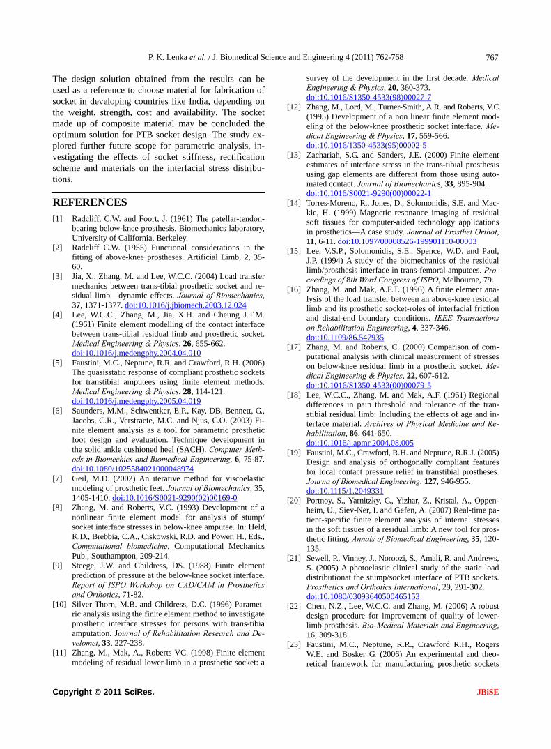
The design solution obtained from the results can be used as a reference to choose material for fabrication of socket in developing countries like India, depending on the weight, strength, cost and availability. The socket made up of composite material may be concluded the optimum solution for PTB socket design. The study ex-plored further future scope for parametric analysis, in-vestigating the effects of socket stiffness, rectification scheme and materials on the interfacial stress distribu-tions.
REFERENCES
[1] Radcliff, C.W. and Foort, J. (1961) The patellar-tendon- bearing below-knee prosthesis. Biomechanics laboratory, University of California, Berkeley.
[2] Radcliff C.W. (1955) Functional considerations in the fitting of above-knee prostheses. Artificial Limb, 2, 35- 60.
[3] Jia, X., Zhang, M. and Lee, W.C.C. (2004) Load transfer mechanics between trans-tibial prosthetic socket and re-sidual limb—dynamic effects. Journal of Biomechanics, 37, 1371-1377. doi:10.1016/j.jbiomech.2003.12.024
[4] Lee, W.C.C., Zhang, M., Jia, X.H. and Cheung J.T.M. (1961) Finite element modelling of the contact interface between trans-tibial residual limb and prosthetic socket. Medical Engineering & Physics, 26, 655-662. doi:10.1016/j.medengphy.2004.04.010
[5] Faustini, M.C., Neptune, R.R. and Crawford, R.H. (2006) The quasisstatic response of compliant prosthetic sockets for transtibial amputees using finite element methods. Medical Engineering & Physics, 28, 114-121. doi:10.1016/j.medengphy.2005.04.019
[6] Saunders, M.M., Schwentker, E.P., Kay, DB, Bennett, G., Jacobs, C.R., Verstraete, M.C. and Njus, G.O. (2003) Fi-nite element analysis as a tool for parametric prosthetic foot design and evaluation. Technique development in the solid ankle cushioned heel (SACH). Computer Meth- ods in Biomechics and Biomedical Engineering, 6, 75-87. doi:10.1080/1025584021000048974
[7] Geil, M.D. (2002) An iterative method for viscoelastic modeling of prosthetic feet. Journal of Biomechanics, 35, 1405-1410. doi:10.1016/S0021-9290(02)00169-0
[8] Zhang, M. and Roberts, V.C. (1993) Development of a nonlinear finite element model for analysis of stump/ socket interface stresses in below-knee amputee. In: Held, K.D., Brebbia, C.A., Ciskowski, R.D. and Power, H., Eds., Computational biomedicine, Computational Mechanics Pub., Southampton, 209-214.
[9] Steege, J.W. and Childress, DS. (1988) Finite element prediction of pressure at the below-knee socket interface. Report of ISPO Workshop on CAD/CAM in Prosthetics and Orthotics, 71-82.
[10] Silver-Thorn, M.B. and Childress, D.C. (1996) Paramet-ric analysis using the finite element method to investigate prosthetic interface stresses for persons with trans-tibia amputation. Journal of Rehabilitation Research and De-velomet, 33, 227-238.
[11] Zhang, M., Mak, A., Roberts VC. (1998) Finite element modeling of residual lower-limb in a prosthetic socket: a
survey of the development in the first decade. Medical Engineering & Physics, 20, 360-373. doi:10.1016/S1350-4533(98)00027-7
[12] Zhang, M., Lord, M., Turner-Smith, A.R. and Roberts, V.C. (1995) Development of a non linear finite element mod-eling of the below-knee prosthetic socket interface. Me- dical Engineering & Physics, 17, 559-566. doi:10.1016/1350-4533(95)00002-5
[13] Zachariah, S.G. and Sanders, J.E. (2000) Finite element estimates of interface stress in the trans-tibial prosthesis using gap elements are different from those using auto-mated contact. Journal of Biomechanics, 33, 895-904. doi:10.1016/S0021-9290(00)00022-1
[14] Torres-Moreno, R., Jones, D., Solomonidis, S.E. and Mac- kie, H. (1999) Magnetic resonance imaging of residual soft tissues for computer-aided technology applications in prosthetics—A case study. Journal of Prosthet Orthot, 11, 6-11. doi:10.1097/00008526-199901110-00003
[15] Lee, V.S.P., Solomonidis, S.E., Spence, W.D. and Paul, J.P. (1994) A study of the biomechanics of the residual limb/prosthesis interface in trans-femoral amputees. Pro- ceedings of 8th Word Congress of ISPO, Melbourne, 79.
[16] Zhang, M. and Mak, A.F.T. (1996) A finite element ana- lysis of the load transfer between an above-knee residual limb and its prosthetic socket-roles of interfacial friction and distal-end boundary conditions. IEEE Transactions on Rehabilitation Engineering, 4, 337-346. doi:10.1109/86.547935
[17] Zhang, M. and Roberts, C. (2000) Comparison of com-putational analysis with clinical measurement of stresses on below-knee residual limb in a prosthetic socket. Me- dical Engineering & Physics, 22, 607-612. doi:10.1016/S1350-4533(00)00079-5
[18] Lee, W.C.C., Zhang, M. and Mak, A.F. (1961) Regional differences in pain threshold and tolerance of the tran-stibial residual limb: Including the effects of age and in-terface material. Archives of Physical Medicine and Re-habilitation, 86, 641-650. doi:10.1016/j.apmr.2004.08.005
[19] Faustini, M.C., Crawford, R.H. and Neptune, R.R.J. (2005) Design and analysis of orthogonally compliant features for local contact pressure relief in transtibial prostheses. Journa of Biomedical Engineering, 127, 946-955. doi:10.1115/1.2049331
[20] Portnoy, S., Yarnitzky, G., Yizhar, Z., Kristal, A., Oppen-heim, U., Siev-Ner, I. and Gefen, A. (2007) Real-time pa-tient-specific finite element analysis of internal stresses in the soft tissues of a residual limb: A new tool for pros-thetic fitting. Annals of Biomedical Engineering, 35, 120- 135.
[21] Sewell, P., Vinney, J., Noroozi, S., Amali, R. and Andrews, S. (2005) A photoelastic clinical study of the static load distributionat the stump/socket interface of PTB sockets. Prosthetics and Orthotics International, 29, 291-302. doi:10.1080/03093640500465153
[22] Chen, N.Z., Lee, W.C.C. and Zhang, M. (2006) A robust design procedure for improvement of quality of lower- limb prosthesis. Bio-Medical Materials and Engineering, 16, 309-318.
[23] Faustini, M.C., Neptune, R.R., Crawford R.H., Rogers W.E. and Bosker G. (2006) An experimental and theo-retical framework for manufacturing prosthetic sockets
Copyright © 2011 SciRes. JBiSE

P. K. Lenka et al. / J. Biomedical Science and Engineering 4 (2011) 762-768
Copyright © 2011 SciRes.
768
JBiSE
for transtibial amputees. IEEE Transactions on Neural Sys- tems and Rehabilitation Engineering, 14, 304-310.
[24] Mtalo, L.B. (2000) Appropriate prosthetic prescription. The ISPO Consensus Conference on Appropriate Ortho- paedic Technology for Low-Income Countries, Moshi, 18- 22 September 2000.
[25] National Institute for the Orthopaedically Handicapped, Kolkata, India. http://www.nioh.in
[26] Jensen, J.S., Craig, J.G., Mtalo, L.B. and Zelaya, C.M. (2004) Clincial field follow up of high density polyeth-ylene (HDPE)-Jaipur Prosthesis technology for transfe- moral amputtee. Journal of Prosthetics and Orthotics, 28, 152-166. doi:10.1080/03093640408726700
[27] COMET 250, QC Inspection Services, Incl (HQ). Burns-ville, USA.
[28] Central Mechanical Engineering Research Institute, Dur- gapur, India. http://www.cmeri.res.in
[29] Kalen, V., Adler, N. and Bleck, E.E. (1986) Electromy-ography of idiopathic toe walking. Journal of Pediatric Orthopaedics, 6, 31-33. doi:10.1097/01241398-198601000-00006
[30] Lyons, K., Perry, J., Gronley, J., Barnes, L. and Antonelli, D. (1983) Timing and relative intensity of hip extensor and abductor muscle action during level and stair ambu-lation: an EMG Study. Journal of the American Physical Therrpy Association, 63, 1597-1605.
[31] Mann, R.A.and Inman, V.T. (1964) Phasic activity of intrinsic muscles of the foot. Journal of Bone and Joint Surgery, 46, 469-481.
[32] Moxham, J., Edwards, R.H.T., Aubier, M, DeTroyer, A, Farkas, G., Macklem, P.T. and Roussos, C. (1982) Changes in EMG power spectrum (high-to-low ratio) with force fatigue in humans. Journal of Applied Physiology, 53, 1094-1099.
[33] Hahl, J. and Taya, M. (2000) Experimental and numerical predictions of the ultimate strength of a low-cost com-posite transtibial prosthesis. Journal of Rehabilitation Re- search and Developemt, 37, 405-413.
[34] Silver-Thron, M.B. (1991) Prediction and experimental verification of residual limb/prosthetic socket interface pressure for below knee amputees (Dissertation). North-western University, Evanstoon.
[35] Zhang, M., Turner-Smith, A.R., Tanner, A. and Robert, V.C. (1998) Clinical investigation of a pressure and shear stress on the transtibial stump with prosthesis. Medical Engineering & Physics, 20, 188-198. doi:10.1016/S1350-4533(98)00013-7
[36] Buis, A.W.P. and Convery, P. (1998) Conventional patel-lar-tendon-bearing (PTB) socket/stump interface dyna- mic pressure distribution recorded during the prosthetic stance phase of gait of a trans-tibial amputee. Prosthetic Orthotic International, 22, 193-198.
[37] Zahedi, S. (year) Atlas of prosthetics. 3rd Edition, Lower Limb Prosthetic Research in 21st Century.
[38] Gibson, R.F. (1994) Principles of composite materials me- chanics. McGraw-Hill, New York.
[39] Hamill, J. and Knutzen, C.N. (1961) Biomechanical basis of human movement. 2nd Edition, William & Wilkins Pub- lisher, Philadelphia, 237.
[40] Lee, W.C.C., Zhang, M., Boone, D.A. and Contoyannis, B. (2004) Finite-element analysis to determine effect of monolimb flexibility on structural strength and interac-tion between residual limb and prosthetic socket. Journal of Rehabilitation Research & Develomet, 41, 775-786. doi:10.1682/JRRD.2004.01.0003
[41] Giancoli, D. (2000) Physics for scientists & engineers. 3rd Edition, Prentice Hall, Upper Saddle River.


![PolyProPylene PolyProPylene Technology Technology · 2 “The [polypropylene] prosthetic technology [...] is an attractive and durable solution for trans-tibial amputees, which can](https://static.fdocuments.in/doc/165x107/5f0fa1467e708231d4451d6a/polypropylene-polypropylene-technology-technology-2-aoethe-polypropylene-prosthetic.jpg)