ANALYSIS OF THE EFFECT OF SLAB THICKNESS ON CRACK WIDTH …
10
Original Research Article: full paper (2021), «EUREKA: Physics and Engineering» Number 2 42 Engineering ANALYSIS OF THE EFFECT OF SLAB THICKNESS ON CRACK WIDTH IN RIGID PAVEMENT SLABS Soehardjono Agoes Department of Civil Engineering 1 [email protected] Aditya Candra Department of Civil Engineering 1 [email protected] 1 Universitas Brawijaya Jalan Veteran, Malang, Indonesia, 65145 Abstract Cracks that occur in rigid pavements include longitudinal cracks, transverse cracks, and corner cracks. The relatively large crack width not only spoils the aesthetics of the concrete structural elements but can also lead to structural failure. This study aims to determine the crack width of a rigid pavement concrete slab located above the subgrade which is considered a beam on an elastic foundation, so that a minimum rigid pavement concrete slab thickness can be recommended. The specimen will be observed at va- rious thicknesses to obtain the optimum thickness. The load used is a centralized monotonous load, which represents the load of the truck vehicle. The research limitation is using a test object in the form of a concrete plate measuring 2000×600 mm which is placed on the ground with CBR = 6 %. The quality of reinforced concrete slabs is fc¢ = 40 MPa and fy = 440.31 MPa. The thickness of the concrete slab varies between 100 mm, 150 mm, and 200 mm. The slab placed on the ground is then given a central loading in the form of a centralized monotonic load. The loading range starts from a load of 2–180 kN with a load interval of 2 kN. The experimental results show that the rigid pavement slab has a bending failure so that the crack pattern that occurs begins with the first crack on the underside of the slab. The crack pattern in terms of slab thickness variation has a similar pattern. The initial crack width on the slab is 0.04 mm. The thicker the slab smaller the crack width at the same load. Based on the maximum allowable crack width = 0.3 mm. For loads between (80–100) kN (Road Class I, II, and III), a minimum thickness of rigid pavement slabs (70–80) mm is recommended. For loads between (130–140) kN, the minimum thickness of the rigid pavement slab (105–115) mm is recommended. Keywords: concrete slab, crack pattern, crack width, load, slab thickness, rigid pavement, road. DOI: 10.21303/2461-4262.2021.001693 1. Introduction The road is a land transportation infrastructure which is very important in the system of move- ment of people and goods. There are several types of road pavement, one of which is rigid pavement. Generally, rigid pavement is used for highway pavements where the ground is soft (subgrade). Pavement serves to provide a flat and smooth surface for vehicles and protect land formations against the adverse effects of weather changes. In the implementation of rigid pavement, there are still damage to structural elements caused by faulting and connection covering materials. Cracks that occur in rigid pavement include longitudinal cracks, transverse cracks and corner cracks. Large crack width not only spoils the aesthetics of the concrete structural elements but can also lead to structural failure. Cracks also cause increased deflection. This is due to a reduction in the flexural stiffness in the fracture when the impact of the tensile concrete below the neutral axis decreases. One of the most common problems found in the rigid pavement is the occurrence of cracks and the spreading mechanism. The pavement damage fatigue cracking occurs due to the repeti- tion of the traffic load which causes the stress to be lower than the tensile strength of the concrete pavement [1]. Damage to the rigid pavement is usually initiated by small cracks in the longitudinal direction. Traffic loads can cause increased cracks in the rigid pavement slab and reduced adhesion between steel reinforcement and concrete. Several studies on crack width have been conducted. Research on the cracking behaviour of reinforced concrete slabs in the analysis and experiments on the failure of reinforced concrete slab structures due to repeated loads [2] and prediction of precast concrete slab life based on fracture mechanics has been carried out. The prediction of crack
Transcript of ANALYSIS OF THE EFFECT OF SLAB THICKNESS ON CRACK WIDTH …
Original Research Article:full paper
(2021), «EUREKA: Physics and Engineering»Number 2
42
Engineering
ANALYSIS OF THE EFFECT OF SLAB THICKNESS ON CRACK WIDTH IN RIGID PAVEMENT SLABS
Soehardjono AgoesDepartment of Civil Engineering1
Aditya CandraDepartment of Civil Engineering1
1Universitas BrawijayaJalan Veteran, Malang, Indonesia, 65145
AbstractCracks that occur in rigid pavements include longitudinal cracks, transverse cracks, and corner cracks. The relatively large
crack width not only spoils the aesthetics of the concrete structural elements but can also lead to structural failure. This study aims to determine the crack width of a rigid pavement concrete slab located above the subgrade which is considered a beam on an elastic foundation, so that a minimum rigid pavement concrete slab thickness can be recommended. The specimen will be observed at va-rious thicknesses to obtain the optimum thickness. The load used is a centralized monotonous load, which represents the load of the truck vehicle. The research limitation is using a test object in the form of a concrete plate measuring 2000×600 mm which is placed on the ground with CBR = 6 %. The quality of reinforced concrete slabs is fc¢ = 40 MPa and fy = 440.31 MPa. The thickness of the concrete slab varies between 100 mm, 150 mm, and 200 mm. The slab placed on the ground is then given a central loading in the form of a centralized monotonic load. The loading range starts from a load of 2–180 kN with a load interval of 2 kN. The experimental results show that the rigid pavement slab has a bending failure so that the crack pattern that occurs begins with the first crack on the underside of the slab. The crack pattern in terms of slab thickness variation has a similar pattern. The initial crack width on the slab is 0.04 mm. The thicker the slab smaller the crack width at the same load. Based on the maximum allowable crack width = 0.3 mm. For loads between (80–100) kN (Road Class I, II, and III), a minimum thickness of rigid pavement slabs (70–80) mm is recommended. For loads between (130–140) kN, the minimum thickness of the rigid pavement slab (105–115) mm is recommended.
Keywords: concrete slab, crack pattern, crack width, load, slab thickness, rigid pavement, road.
DOI: 10.21303/2461-4262.2021.001693
1. IntroductionThe road is a land transportation infrastructure which is very important in the system of move-
ment of people and goods. There are several types of road pavement, one of which is rigid pavement. Generally, rigid pavement is used for highway pavements where the ground is soft (subgrade). Pavement serves to provide a flat and smooth surface for vehicles and protect land formations against the adverse effects of weather changes. In the implementation of rigid pavement, there are still damage to structural elements caused by faulting and connection covering materials. Cracks that occur in rigid pavement include longitudinal cracks, transverse cracks and corner cracks. Large crack width not only spoils the aesthetics of the concrete structural elements but can also lead to structural failure. Cracks also cause increased deflection. This is due to a reduction in the flexural stiffness in the fracture when the impact of the tensile concrete below the neutral axis decreases.
One of the most common problems found in the rigid pavement is the occurrence of cracks and the spreading mechanism. The pavement damage fatigue cracking occurs due to the repeti-tion of the traffic load which causes the stress to be lower than the tensile strength of the concrete pavement [1]. Damage to the rigid pavement is usually initiated by small cracks in the longitudinal direction. Traffic loads can cause increased cracks in the rigid pavement slab and reduced adhesion between steel reinforcement and concrete. Several studies on crack width have been conducted. Research on the cracking behaviour of reinforced concrete slabs in the analysis and experiments on the failure of reinforced concrete slab structures due to repeated loads [2] and prediction of precast concrete slab life based on fracture mechanics has been carried out. The prediction of crack
Original Research Article:full paper
(2021), «EUREKA: Physics and Engineering»Number 2
43
Engineering
width using analytical and experimental methods on bridge slabs with composite precast panels has resulted in crack width formula, taking into account the thickness of the concrete cover and the amount of reinforcement [3]. Another study is the prediction of longitudinal fatigue cracks in reinforced concrete pavements (JPCP) using the RadiCAL method [4]. Testing the characteristics of porous asphalt pavement and concrete on elastic foundations of clay soil with monotonic centric static loading obtained load, asphalt tensile strain, concrete compressive strain, concrete tensile strain and deflection at maximum conditions.
Research on cracks in concrete slabs as the rigid pavement is expected to produce findings of the pattern and width of cracks in concrete slabs on rigid pavements that are located on elastic soil supports. This research can provide an understanding of the behaviour of rigid pavement concrete slabs on elastic supports due to monotonic loads. The problem of crack patterns and the formulation of crack widths that occur in rigid pavement slabs due to repeated loads can be used to predict the level of damage and the useful life of concrete structural elements. This study aims to determine the crack width of a rigid pavement concrete slab located above the subgrade which is considered a beam on an elastic foundation, so that a minimum rigid pavement concrete slab thickness can be recommended.
2. Materials and methodsThe research purpose is to measure the optimum thickness of the rigid pavement slab in terms
of the crack width to obtain a base reference for the slab’s thickness according to the road class.
2. 1. HighwayHighway can be grouped according to Road Class based on standardization of road infra-
structure provision. The distribution of road classes is regulated by the provisions of laws and regu-lations in the field of road traffic and transportation. The regulation of road classes based on the specifications for the provision of road infrastructure is grouped into freeways, highways, medium roads and small roads. Meanwhile, the division of road classes according to Government Regulation Number 22 the Year 2009 concerning Road Traffic and Transportation (clause 19) is as follows:
– Class I roadClass I roads are arterial and collector roads that can be passed by motorized vehicles with
a width not exceeding 2,500 (two thousand five hundred) millimeters, a length not exceeding 18,000 (eighteen thousand) millimeters, with a maximum size of 4,200 (four thousand two hundred) millimeters and the heaviest axle load of 10 (ten) tons.
– Class II roadClass II roads are arterial, collector, local and environmental roads that can be passed by
motorized vehicles with a width not exceeding 2,500 (two thousand five hundred) millimeters, a length not exceeding 12,000 (twelve thousand) millimeters, with a maximum size of 4,200 (four thousand two hundred) millimeters and the heaviest axle load of 8 (eight) tons.
– Class III roadClass III roads are arterial, collector, local and environmental roads that can be passed
by motorized vehicles with a width not exceeding 2,100 (two thousand one hundred) millimeters, length not exceeding 9,000 (nine thousand) millimeters, with a maximum size of 3,500 (three thou-sand five hundred) millimeter and the heaviest axle payload is 8 (eight) tons.
– Special class roadSpecial class roads are arterial roads that can be passed by motor vehicles with a width
exceeding 2,500 (two thousand five hundred) millimeters, a length exceeding 18,000 (eighteen thousand) millimeters, a maximum size of 4,200 (four thousand two hundred) millimeters and the heaviest axle load more than 10 (ten) tons.
2. 2. Concrete Crack WidthThe maximum crack width must be considered to keep the concrete appearance from the
outside. The limitation of crack width depends on several factors including crack position, crack length and crack surface texture. For reasons of aesthetic comfort, the crack width ranges from 0.25 mm to 0.38 mm [5, 6].
Original Research Article:full paper
(2021), «EUREKA: Physics and Engineering»Number 2
44
Engineering
ACI Committee 224 (1972) suggested the maximum crack width as shown in Table 1 to pro-tect steel reinforcement against corrosion hazards [7]. Under these circumstances ACI 318 (1995) [8] suggested additional distributed tensile reinforcement to limit the crack width.
Table 1Maximum allowable crack width (ACI Committee 224) [7]
External Environmental Conditions Maximum allowable crack width (mm)
Air dry or protective coating 0.40
Moist, wet air, or soil 0.30
Ice (snow) or chemicals 0.20
Seawater in both wet and dry conditions 0.15
Water retaining wall 0.10
Based on the recommendation of the American Concrete Institute (ACI) 318-89 (1990) [9] and SNI 03-2847-2002 [10] it has accommodated the crack problem if fy > 300 N/mm2 then the maximum positive and negative moments will be proportional with Z is equal to:
Z f dc As= ⋅ ≤3 25 MN m (outdoor)
where, fs is the steel stress at work load ( fs ≤ 0.6fy) (N/mm2), dc is a concrete cover (mm), A is the area around tensile reinforcement (mm2).
As an alternative to calculating the Z parameter value, the crack width can be calculated:
w f dc Amaks s= ⋅ ⋅ ⋅ ⋅ ⋅ ≤−11 10 0 306 3β . mm (outdoor)
where, fs = steel stress at work load ( fs ≤ 0.6fy) (N/mm2), β is the ratio between the distance from the point on the crack width to the neutral axis divided by the distance from the center of gravity of the tensile reinforcement to the neutral axis (dimensionless), dc of concrete cover (mm), A is area around tensile reinforcement (mm2).
In addition, the reinforcement spacing must not exceed s = (95000/fs) – 2.5dc (mm), but can-not be greater than 300 (252/fs) (mm).
2. 3. Cause of CracksThe causes of cracks in reinforced concrete are classified into two categories, namely
cracks caused by external loads and cracks caused by other than external loads [11, 12]. Types of cracks caused by external loads are bending cracks and shear cracks. Flexural cracks occur in the cross-section of the tensile area and have a sharp or tapered crack shape where the width of the largest crack is on the surface and the closer to the neutral line the crack is getting smaller. While shear cracks usually occur on thin webs where there is a large shear force.
Starting from micro-cracks it can accumulate into larger crack types due to increased exter-nal loads. This crack is caused by increased stress around the ribs of the reinforced concrete which is restrained without being visible from the cross-sectional surface of the concrete. The second category of cracks is cracking that is not caused by external loads due to shrinkage or temperature differences. This crack usually occurs in-floor slab structures and the width of the crack due to shrinkage is relatively uniform. If cracking due to shrinkage is not considered, it will reduce the torque and deflection capacity.
2. 4. Spacing and Crack Width in Flexural CracksFlexural cracks begin to occur because the tensile stress that occurs in the concrete has
exceeded its critical stress. After the initial crack formation is formed, it is followed by a transi-tion from the elastic region to plastic which contributes to an increase in crack width. However,
Original Research Article:full paper
(2021), «EUREKA: Physics and Engineering»Number 2
45
Engineering
in the area around the steel reinforcement, because there is a bond between steel and concrete, the stress and strain are maintained to a certain extent, thereby reducing the crack width compared to a concrete surface without reinforcement [12].
Flexural cracks in each moment region of the beam develop at regular intervals, but at a constant moment region, these flexural cracks develop at discrete intervals. The location depends on where the distribution of the concrete weakness occurs and these cracks sometimes occur ran-domly [13] concluded that the exact location of cracks due to constant moment is very difficult to predict with accuracy. However, the maximum and minimum spacing of adjacent cracks and the maximum crack width can be predicted with sufficient accuracy through the analysis of the increas-ing stresses of the concrete in the tensile area.
Assuming that the treatment for prestressed concrete can be used by modifying the formula-tion for non-prestressed concrete elements [14]. In the classical theory for reinforced concrete tensile elements, it states that the crack width is equal to the steel strain minus the concrete strain [15]. The strain due to temperature and shrinkage does not affect the crack width and assumes uniform concrete strain over the crack distance [16]. For beams, even when shear is zero and moment is constant, large local bond stresses exist adjacent to each flexural crack. At the crack, most of the tension is carried by the bars and the steel stress is maximum [17]. Based on an assumed model of crack formation, expres-sions are developed for maximum crack spacing and crack width in reinforced concrete beams in pure flexure. Both the maximum crack width at the tension surface of the member and the maximum crack width at the surface of the reinforcement are considered, and the former and an upper bound on the lat-ter are related to the crack spacing through a slip modulus between the concrete and the steel [18–20].
Some formulas related to crack width (w) and steel stress ( fs) on rigid pavement slabs include:Based on [5, 6], the crack width depends on the stress of the steel, and the parameters β, dc, A:
w k f dc Amaks s= ⋅ ⋅ ⋅ ⋅13β mm.
Based on [14], the crack width depends on the stress of the steel, and the parameters β, dc, At, As:
w f dct
smaks s= ⋅ ⋅ ⋅ ⋅
−2 55 10 6
0 5
..
β∆∆
mm.
Based on [10], the crack width depends on the steel stress, and the parameters β, dc, A:
w f dc Amaks s= ⋅ ⋅ ⋅ ⋅ ⋅−11 10 6 3β mm,
where, fs is the steel stress at work load ( fs ≤ 0.6fy) (N/mm2), dc is a concrete cover (mm), A is the area around tensile reinforcement (mm2), k1 is a unit dependent constant, β is the ratio between the distance from the point on the crack width to the neutral axis divided by the distance from the center of gravity of the tensile reinforcement to the neutral axis (dimensionless), At is the area of the concrete drawn below the neutral line (mm2), As is the area of the reinforcing bar (mm2).
Of all the existing parameters, the steel stress parameter fs is the parameter that has the greatest influence on the crack width w. According to several researchers, the crack width value for steel stress and the regulations used in Indonesia will be compared with the results of experiments in the laboratory. The specimens were varied for different thicknesses of rigid pavement slabs, namely 100 mm, 150 mm, and 200 mm.
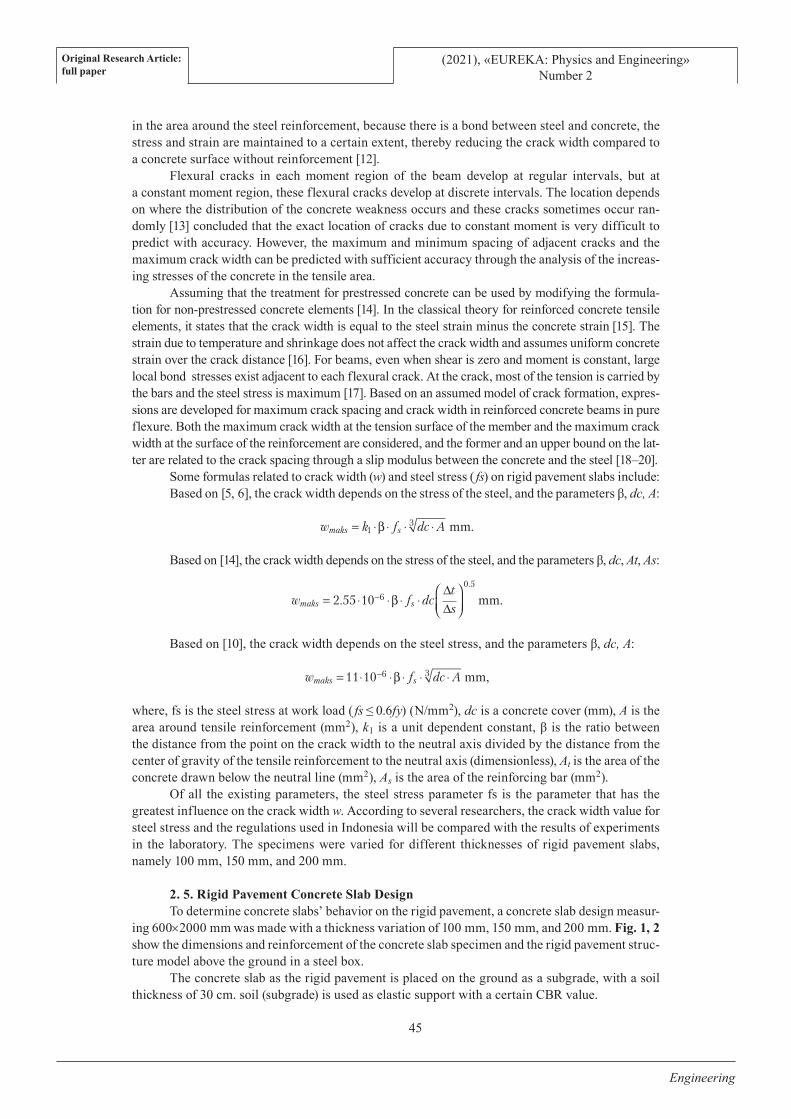
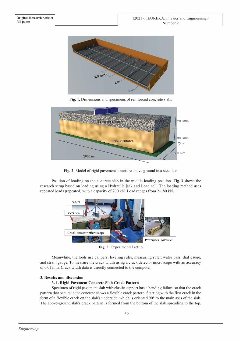
2. 5. Rigid Pavement Concrete Slab DesignTo determine concrete slabs’ behavior on the rigid pavement, a concrete slab design measur-
ing 600×2000 mm was made with a thickness variation of 100 mm, 150 mm, and 200 mm. Fig. 1, 2 show the dimensions and reinforcement of the concrete slab specimen and the rigid pavement struc-ture model above the ground in a steel box.
The concrete slab as the rigid pavement is placed on the ground as a subgrade, with a soil thickness of 30 cm. soil (subgrade) is used as elastic support with a certain CBR value.
Original Research Article:full paper
(2021), «EUREKA: Physics and Engineering»Number 2
46
Engineering
Fig. 1. Dimensions and specimens of reinforced concrete slabs
Fig. 2. Model of rigid pavement structure above ground in a steel box
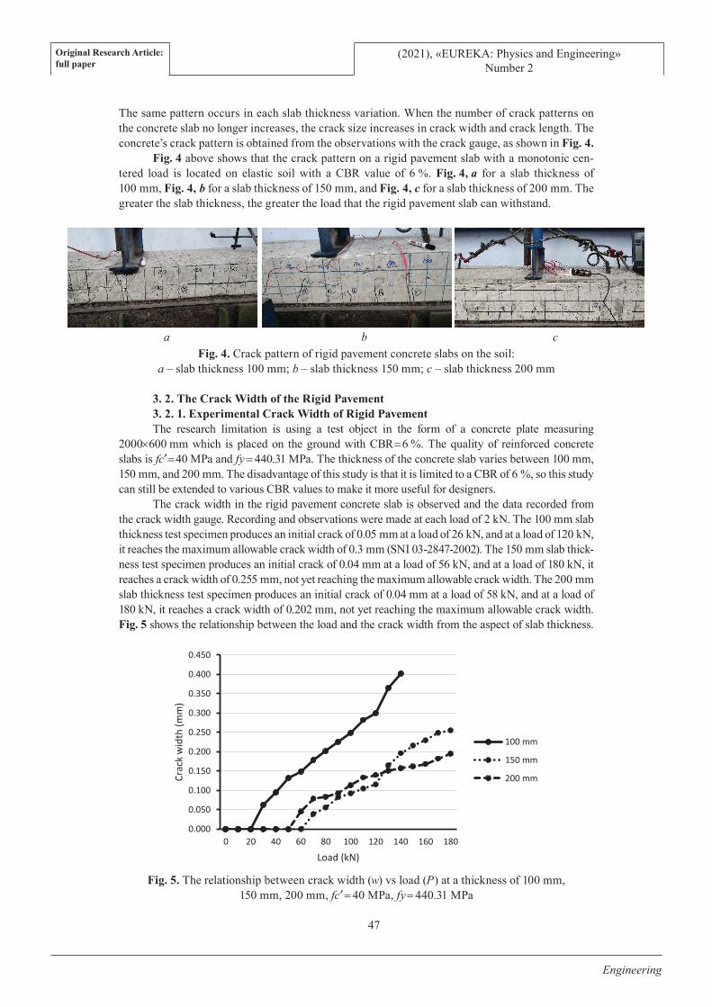
Position of loading on the concrete slab in the middle loading position. Fig. 3 shows the research setup based on loading using a Hydraulic jack and Load cell. The loading method uses repeated loads (repeated) with a capacity of 200 kN. Load ranges from 2–180 kN.
Fig. 3. Experimental setup
Meanwhile, the tools use calipers, leveling ruler, measuring ruler, water pass, dial gauge, and strain gauge. To measure the crack width using a crack detector microscope with an accuracy of 0.01 mm. Crack width data is directly connected to the computer.
3. Results and discussion3. 1. Rigid Pavement Concrete Slab Crack PatternSpecimen of rigid pavement slab with elastic support has a bending failure so that the crack
pattern that occurs in the concrete shows a flexible crack pattern. Starting with the first crack in the form of a flexible crack on the slab’s underside, which is oriented 90° to the main axis of the slab. The above-ground slab’s crack pattern is formed from the bottom of the slab spreading to the top.
Soil CBR=6%
Concrete slabs
600 mm 2000 mm
200 mm
300 mm
Fig. 3 Experimental Set up
Original Research Article:full paper
(2021), «EUREKA: Physics and Engineering»Number 2
47
Engineering
The same pattern occurs in each slab thickness variation. When the number of crack patterns on the concrete slab no longer increases, the crack size increases in crack width and crack length. The concrete’s crack pattern is obtained from the observations with the crack gauge, as shown in Fig. 4.
Fig. 4 above shows that the crack pattern on a rigid pavement slab with a monotonic cen-tered load is located on elastic soil with a CBR value of 6 %. Fig. 4, a for a slab thickness of 100 mm, Fig. 4, b for a slab thickness of 150 mm, and Fig. 4, c for a slab thickness of 200 mm. The greater the slab thickness, the greater the load that the rigid pavement slab can withstand.
Fig. 4. Crack pattern of rigid pavement concrete slabs on the soil: a – slab thickness 100 mm; b – slab thickness 150 mm; c – slab thickness 200 mm
3. 2. The Crack Width of the Rigid Pavement3. 2. 1. Experimental Crack Width of Rigid PavementThe research limitation is using a test object in the form of a concrete plate measuring
2000×600 mm which is placed on the ground with CBR = 6 %. The quality of reinforced concrete slabs is fc¢ = 40 MPa and fy = 440.31 MPa. The thickness of the concrete slab varies between 100 mm, 150 mm, and 200 mm. The disadvantage of this study is that it is limited to a CBR of 6 %, so this study can still be extended to various CBR values to make it more useful for designers.
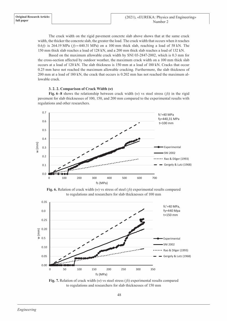
The crack width in the rigid pavement concrete slab is observed and the data recorded from the crack width gauge. Recording and observations were made at each load of 2 kN. The 100 mm slab thickness test specimen produces an initial crack of 0.05 mm at a load of 26 kN, and at a load of 120 kN, it reaches the maximum allowable crack width of 0.3 mm (SNI 03-2847-2002). The 150 mm slab thick-ness test specimen produces an initial crack of 0.04 mm at a load of 56 kN, and at a load of 180 kN, it reaches a crack width of 0.255 mm, not yet reaching the maximum allowable crack width. The 200 mm slab thickness test specimen produces an initial crack of 0.04 mm at a load of 58 kN, and at a load of 180 kN, it reaches a crack width of 0.202 mm, not yet reaching the maximum allowable crack width. Fig. 5 shows the relationship between the load and the crack width from the aspect of slab thickness.
Fig. 5. The relationship between crack width (w) vs load (P) at a thickness of 100 mm, 150 mm, 200 mm, fc¢ = 40 MPa, fy = 440.31 MPa
a b c
0.000
0.050
0.100
0.150
0.200
0.250
0.300
0.350
0.400
0.450
0 20 40 60 80 100 120 140 160 180
Crac
k w
idth
(mm
)
Load (kN)
100 mm
150 mm
200 mm
Original Research Article:full paper
(2021), «EUREKA: Physics and Engineering»Number 2
48
Engineering
The crack width on the rigid pavement concrete slab above shows that at the same crack width, the thicker the concrete slab, the greater the load. The crack width that occurs when it reaches 0.6 fy is 264.19 MPa ( fy = 440.31 MPa) on a 100 mm thick slab, reaching a load of 58 kN. The 150 mm thick slab reaches a load of 128 kN, and a 200 mm thick slab reaches a load of 132 kN.
Based on the maximum allowable crack width by SNI 03-2847-2002, which is 0.3 mm for the cross-section affected by outdoor weather, the maximum crack width on a 100 mm thick slab occurs at a load of 120 kN. The slab thickness is 150 mm at a load of 180 kN. Cracks that occur 0.25 mm have not reached the maximum allowable cracking. Furthermore, the slab thickness of 200 mm at a load of 180 kN, the crack that occurs is 0.202 mm has not reached the maximum al-lowable crack.
3. 2. 2. Comparison of Crack Width (w)Fig. 6–8 shows the relationship between crack width (w) vs steel stress ( fs) in the rigid
pavement for slab thicknesses of 100, 150, and 200 mm compared to the experimental results with regulations and other researchers.
Fig. 6. Relation of crack width (w) vs stress of steel ( fs) experimental results compared to regulations and researchers for slab thicknesses of 100 mm
Fig. 7. Relation of crack width (w) vs steel stress ( fs) experimental results compared to regulations and researchers for slab thicknesses of 150 mm
0.0
0.1
0.2
0.3
0.4
0.5
0.6
0.7
0 100 200 300 400 500 600 700
w (m
m)
fs (MPa)
fc'=40 MPafy=440,31 MPat=100 mm
Experimental
SNI 2002
Rao & Dilger (1993)
Gergely & Lutz (1968)
0.00
0.05
0.10
0.5
0.20
0.25
0.0
0.35
0 50 100 150 200 250 300 350
w (m
m)
fs (MPa)
fc'=40 MPa, fy=440 Mpat=150 mm
Experimental
SNI 2002
Rao & Dilger (1993)
Gergely & Lutz (1968)
Original Research Article:full paper
(2021), «EUREKA: Physics and Engineering»Number 2
49
Engineering
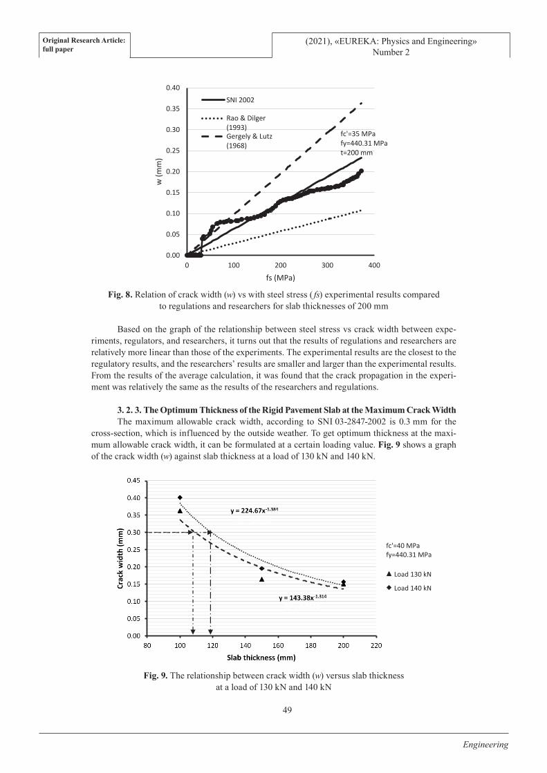
Fig. 8. Relation of crack width (w) vs with steel stress ( fs) experimental results compared to regulations and researchers for slab thicknesses of 200 mm
Based on the graph of the relationship between steel stress vs crack width between expe-riments, regulators, and researchers, it turns out that the results of regulations and researchers are relatively more linear than those of the experiments. The experimental results are the closest to the regulatory results, and the researchers’ results are smaller and larger than the experimental results. From the results of the average calculation, it was found that the crack propagation in the experi-ment was relatively the same as the results of the researchers and regulations.
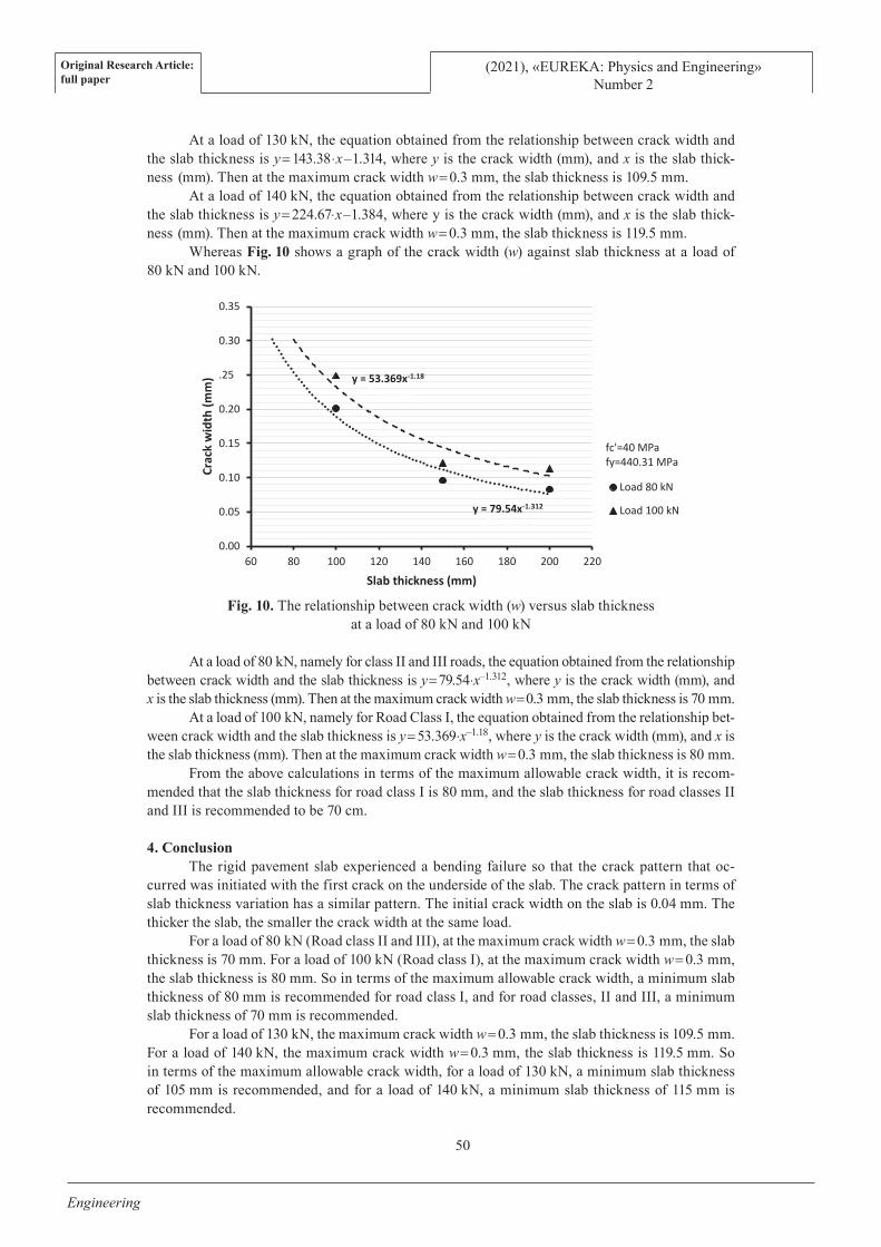
3. 2. 3. The Optimum Thickness of the Rigid Pavement Slab at the Maximum Crack WidthThe maximum allowable crack width, according to SNI 03-2847-2002 is 0.3 mm for the
cross-section, which is influenced by the outside weather. To get optimum thickness at the maxi-mum allowable crack width, it can be formulated at a certain loading value. Fig. 9 shows a graph of the crack width (w) against slab thickness at a load of 130 kN and 140 kN.
Fig. 9. The relationship between crack width (w) versus slab thickness at a load of 130 kN and 140 kN
0.00
0.05
0.10
0.15
0.20
0.25
0.30
0.35
0.40
0 100 200 300 400
w (m
m)
fs (MPa)
fc'=35 MPa fy=440.31 MPa t=200 mm
SNI 2002
Rao & Dilger(1993)Gergely & Lutz(1968)
Fig 9. The relationship between crack width (w) vsslab thickness at a load of 130 kN and 140 kN
fc'=40 MPafy=440.31 MPa
Load 130 kN
Load 140 kN
Original Research Article:full paper
(2021), «EUREKA: Physics and Engineering»Number 2
50
Engineering
At a load of 130 kN, the equation obtained from the relationship between crack width and the slab thickness is y = 143.38⋅x–1.314, where y is the crack width (mm), and x is the slab thick-ness (mm). Then at the maximum crack width w = 0.3 mm, the slab thickness is 109.5 mm.
At a load of 140 kN, the equation obtained from the relationship between crack width and the slab thickness is y = 224.67⋅x–1.384, where y is the crack width (mm), and x is the slab thick-ness (mm). Then at the maximum crack width w = 0.3 mm, the slab thickness is 119.5 mm.
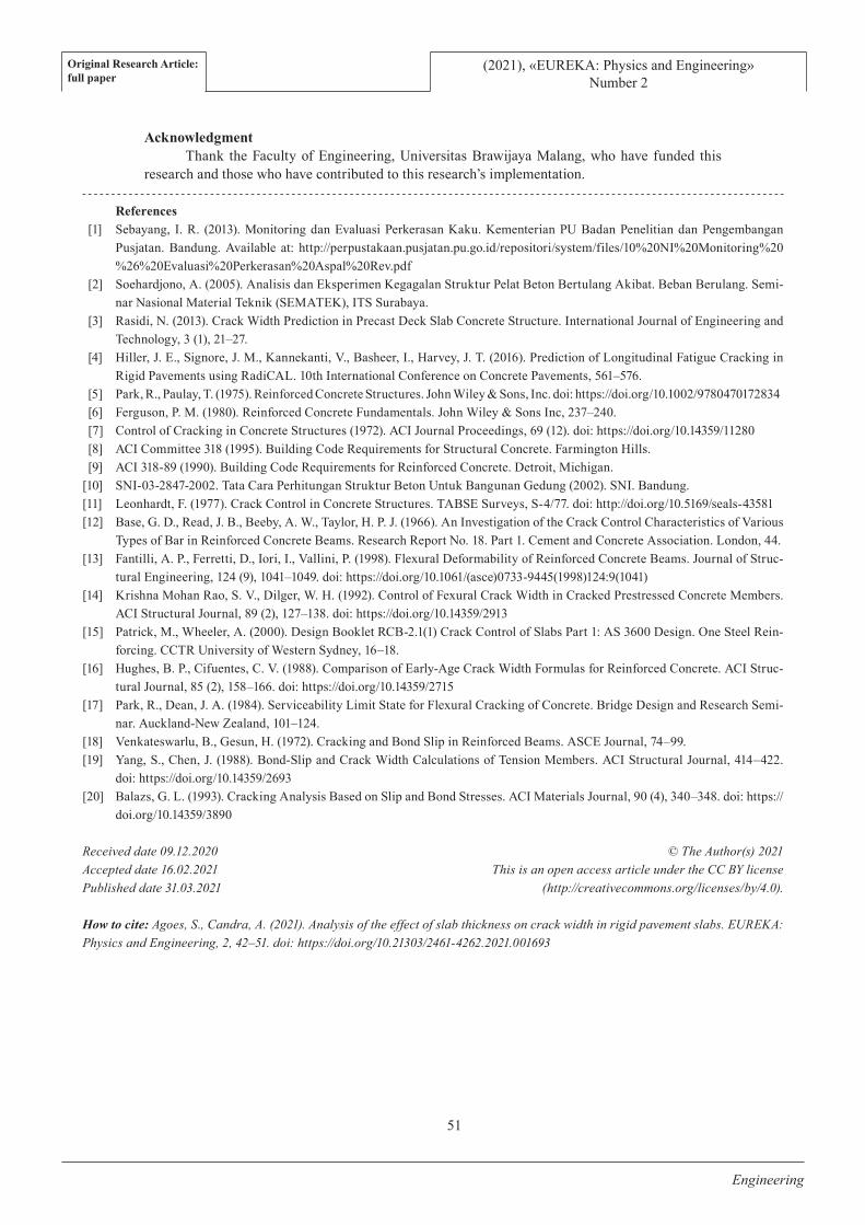
Whereas Fig. 10 shows a graph of the crack width (w) against slab thickness at a load of 80 kN and 100 kN.
Fig. 10. The relationship between crack width (w) versus slab thickness at a load of 80 kN and 100 kN
At a load of 80 kN, namely for class II and III roads, the equation obtained from the relationship between crack width and the slab thickness is y = 79.54⋅x–1.312, where y is the crack width (mm), and x is the slab thickness (mm). Then at the maximum crack width w = 0.3 mm, the slab thickness is 70 mm.
At a load of 100 kN, namely for Road Class I, the equation obtained from the relationship bet-ween crack width and the slab thickness is y = 53.369⋅x–1.18, where y is the crack width (mm), and x is the slab thickness (mm). Then at the maximum crack width w = 0.3 mm, the slab thickness is 80 mm.
From the above calculations in terms of the maximum allowable crack width, it is recom-mended that the slab thickness for road class I is 80 mm, and the slab thickness for road classes II and III is recommended to be 70 cm.
4. ConclusionThe rigid pavement slab experienced a bending failure so that the crack pattern that oc-
curred was initiated with the first crack on the underside of the slab. The crack pattern in terms of slab thickness variation has a similar pattern. The initial crack width on the slab is 0.04 mm. The thicker the slab, the smaller the crack width at the same load.
For a load of 80 kN (Road class II and III), at the maximum crack width w = 0.3 mm, the slab thickness is 70 mm. For a load of 100 kN (Road class I), at the maximum crack width w = 0.3 mm, the slab thickness is 80 mm. So in terms of the maximum allowable crack width, a minimum slab thickness of 80 mm is recommended for road class I, and for road classes, II and III, a minimum slab thickness of 70 mm is recommended.
For a load of 130 kN, the maximum crack width w = 0.3 mm, the slab thickness is 109.5 mm. For a load of 140 kN, the maximum crack width w = 0.3 mm, the slab thickness is 119.5 mm. So in terms of the maximum allowable crack width, for a load of 130 kN, a minimum slab thickness of 105 mm is recommended, and for a load of 140 kN, a minimum slab thickness of 115 mm is recommended.
y = 79.54x-1.312
R² = 0.9279
y = 53.369x-1.18
R² = 0.8902
0.00
0.05
0.10
0.15
0.20
.25
0.30
0.35
60 80 100 180 200 220
Crac
k w
idth
(mm
)
120 140 160Slab thickness (mm)
fc'=40 MPafy=440.31 MPa
Load 80 kN
Load 100 kN
Original Research Article:full paper
(2021), «EUREKA: Physics and Engineering»Number 2
51
Engineering
AcknowledgmentThank the Faculty of Engineering, Universitas Brawijaya Malang, who have funded this
research and those who have contributed to this research’s implementation.
References[1] Sebayang, I. R. (2013). Monitoring dan Evaluasi Perkerasan Kaku. Kementerian PU Badan Penelitian dan Pengembangan
Pusjatan. Bandung. Available at: http://perpustakaan.pusjatan.pu.go.id/repositori/system/files/10%20NI%20Monitoring%20%26%20Evaluasi%20Perkerasan%20Aspal%20Rev.pdf
[2] Soehardjono, A. (2005). Analisis dan Eksperimen Kegagalan Struktur Pelat Beton Bertulang Akibat. Beban Berulang. Semi-nar Nasional Material Teknik (SEMATEK), ITS Surabaya.
[3] Rasidi, N. (2013). Crack Width Prediction in Precast Deck Slab Concrete Structure. International Journal of Engineering and Technology, 3 (1), 21–27.
[4] Hiller, J. E., Signore, J. M., Kannekanti, V., Basheer, I., Harvey, J. T. (2016). Prediction of Longitudinal Fatigue Cracking in Rigid Pavements using RadiCAL. 10th International Conference on Concrete Pavements, 561–576.
[5] Park, R., Paulay, T. (1975). Reinforced Concrete Structures. John Wiley & Sons, Inc. doi: https://doi.org/10.1002/9780470172834 [6] Ferguson, P. M. (1980). Reinforced Concrete Fundamentals. John Wiley & Sons Inc, 237–240.[7] Control of Cracking in Concrete Structures (1972). ACI Journal Proceedings, 69 (12). doi: https://doi.org/10.14359/11280 [8] ACI Committee 318 (1995). Building Code Requirements for Structural Concrete. Farmington Hills.[9] ACI 318-89 (1990). Building Code Requirements for Reinforced Concrete. Detroit, Michigan.
[10] SNI-03-2847-2002. Tata Cara Perhitungan Struktur Beton Untuk Bangunan Gedung (2002). SNI. Bandung.[11] Leonhardt, F. (1977). Crack Control in Concrete Structures. TABSE Surveys, S-4/77. doi: http://doi.org/10.5169/seals-43581[12] Base, G. D., Read, J. B., Beeby, A. W., Taylor, H. P. J. (1966). An Investigation of the Crack Control Characteristics of Various
Types of Bar in Reinforced Concrete Beams. Research Report No. 18. Part 1. Cement and Concrete Association. London, 44.[13] Fantilli, A. P., Ferretti, D., Iori, I., Vallini, P. (1998). Flexural Deformability of Reinforced Concrete Beams. Journal of Struc-
tural Engineering, 124 (9), 1041–1049. doi: https://doi.org/10.1061/(asce)0733-9445(1998)124:9(1041) [14] Krishna Mohan Rao, S. V., Dilger, W. H. (1992). Control of Fexural Crack Width in Cracked Prestressed Concrete Members.
ACI Structural Journal, 89 (2), 127–138. doi: https://doi.org/10.14359/2913 [15] Patrick, M., Wheeler, A. (2000). Design Booklet RCB-2.1(1) Crack Control of Slabs Part 1: AS 3600 Design. One Steel Rein-
forcing. CCTR University of Western Sydney, 16–18. [16] Hughes, B. P., Cifuentes, C. V. (1988). Comparison of Early-Age Crack Width Formulas for Reinforced Concrete. ACI Struc-
tural Journal, 85 (2), 158–166. doi: https://doi.org/10.14359/2715 [17] Park, R., Dean, J. A. (1984). Serviceability Limit State for Flexural Cracking of Concrete. Bridge Design and Research Semi-
nar. Auckland-New Zealand, 101–124.[18] Venkateswarlu, B., Gesun, H. (1972). Cracking and Bond Slip in Reinforced Beams. ASCE Journal, 74–99.[19] Yang, S., Chen, J. (1988). Bond-Slip and Crack Width Calculations of Tension Members. ACI Structural Journal, 414–422.
doi: https://doi.org/10.14359/2693 [20] Balazs, G. L. (1993). Cracking Analysis Based on Slip and Bond Stresses. ACI Materials Journal, 90 (4), 340–348. doi: https://
doi.org/10.14359/3890
© The Author(s) 2021This is an open access article under the CC BY license
(http://creativecommons.org/licenses/by/4.0).
Received date 09.12.2020Accepted date 16.02.2021Published date 31.03.2021
How to cite: Agoes, S., Candra, A. (2021). Analysis of the effect of slab thickness on crack width in rigid pavement slabs. EUREKA: Physics and Engineering, 2, 42–51. doi: https://doi.org/10.21303/2461-4262.2021.001693