ANALYSIS OF STRESS RELIEVING FEATURES OF ASYMMETRIC SPUR … 2016-01-02 · ... Spur and Helical...
7
Novateur Publication’s International Journal of Innovation in Engineering, Research and Technology [IJIERT] ICITDCEME’15 Conference Proceedings ISSN No - 2394-3696 1 | Page ANALYSIS OF STRESS RELIEVING FEATURES OF ASYMMETRIC SPUR GEAR Prof.G.B.Ingole P.G student, Mechanical Engineering Department, Sinhgad College of Engineering, Pune, Savitribai Phule Pune University, India. Prof.Dr. S.B.WADKAR Professor, Mechanical Engineering Department, Sinhgad College of Engineering, Pune, Savitribai Phule Pune University, India. Dr. D.S.WATWISAVE Professor, Mechanical Engineering Department, Sinhgad College of Engineering, Pune, Savitribai Phule Pune University, India. ABSTRACT Gears are commonly used for transmitting power. They develop high stress concentration at the root and the point of contact. The repeated stressing on the fillets causes the fatigue failure of gear tooth. If gear fails in tensile fatigue, the results are catastrophic and occur with little or no warnings. Therefore for all the reasons mentioned above, this work is of more practical importance. For many years, gear design has been improved by using improved material, hardening surfaces with heat treatment and carburization, and shot penning to improve surface finish etc. Few more efforts have been made to improve the durability and strength by altering the pressure angle, using the asymmetric teeth, altering the geometry of root fillet curve and so on. Most of the above methods do not guarantees the interchange ability of the existing gear systems. The main objective of this seminar is to add circular shaped holes to reduce stress concentration. This work presents the possibilities of using the stress redistribution techniques by introducing the stress relieving features in the stressed zone to the advantage of reduction of root fillet stress in spur gear. KEYWORDS: Asymmetric Spur Gear, Strain Gauges and Strain Meter, CAE INTRODUCTION 1.1 GEAR TECHNOLOGY Gears are the most common means of transmitting power in the modern mechanical engineering world. They vary from a tiny size used in watches to the large gears used in watches to the large gears used in lifting mechanisms and speed reducers. They form vital elements of main and ancillary mechanisms in many machines such as automobiles, tractors, metal cutting machine tools etc. Toothed gears are used to change the speed and power ratio as well as direction between input and output. LAW OF GEARING A primary requirement of gears is the constant angular velocities or proportionality of position transmission. Precision instruments require positioning fidelity. High-speed and/or high-power gear trains also require transmission at constant angular velocities in order to avoid severe dynamic problems. Constant velocity (i.e., constant ratio) motion transmission is defined as "conjugate action" of the gear tooth profiles. A geometric relationship can be derived for the form of the tooth profiles to provide conjugate action, which is summarized as the Law of Gearing as follows: "A common normal to the tooth profiles at their point of contact must, in all positions of the contacting teeth, pass through a fixed point on the line-of-centres called the pitch point." Any two curves or profiles engaging each other and satisfying the law of gearing are conjugate curves. Fig 1.1 shows two mating gear teeth, in which • Tooth profile 1 drives tooth profile 2 by the instantaneous contact point K. • N 1 N 2 is the common normal of the two profiles. • N 1 is the foot of the perpendicular from O 1 to N 1 N 2 • N 2 is the foot of the perpendicular from O 2 to N 1 N 2 .
Transcript of ANALYSIS OF STRESS RELIEVING FEATURES OF ASYMMETRIC SPUR … 2016-01-02 · ... Spur and Helical...
Novateur Publication’s
International Journal of Innovation in Engineering, Research and Technology [IJIERT]
ICITDCEME’15 Conference Proceedings
ISSN No - 2394-3696
1 | P a g e
ANALYSIS OF STRESS RELIEVING FEATURES OF ASYMMETRIC
SPUR GEAR
Prof.G.B.Ingole
P.G student, Mechanical Engineering Department, Sinhgad College of Engineering, Pune,
Savitribai Phule Pune University, India.
Prof.Dr. S.B.WADKAR
Professor, Mechanical Engineering Department, Sinhgad College of Engineering, Pune,
Savitribai Phule Pune University, India.
Dr. D.S.WATWISAVE
Professor, Mechanical Engineering Department, Sinhgad College of Engineering, Pune,
Savitribai Phule Pune University, India.
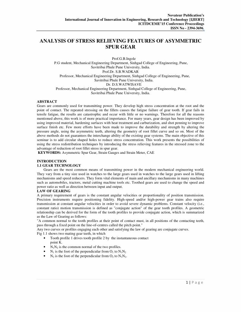
ABSTRACT
Gears are commonly used for transmitting power. They develop high stress concentration at the root and the
point of contact. The repeated stressing on the fillets causes the fatigue failure of gear tooth. If gear fails in
tensile fatigue, the results are catastrophic and occur with little or no warnings. Therefore for all the reasons
mentioned above, this work is of more practical importance. For many years, gear design has been improved by
using improved material, hardening surfaces with heat treatment and carburization, and shot penning to improve
surface finish etc. Few more efforts have been made to improve the durability and strength by altering the
pressure angle, using the asymmetric teeth, altering the geometry of root fillet curve and so on. Most of the
above methods do not guarantees the interchange ability of the existing gear systems. The main objective of this
seminar is to add circular shaped holes to reduce stress concentration. This work presents the possibilities of
using the stress redistribution techniques by introducing the stress relieving features in the stressed zone to the
advantage of reduction of root fillet stress in spur gear.
KEYWORDS: Asymmetric Spur Gear, Strain Gauges and Strain Meter, CAE
INTRODUCTION
1.1 GEAR TECHNOLOGY Gears are the most common means of transmitting power in the modern mechanical engineering world.
They vary from a tiny size used in watches to the large gears used in watches to the large gears used in lifting
mechanisms and speed reducers. They form vital elements of main and ancillary mechanisms in many machines
such as automobiles, tractors, metal cutting machine tools etc. Toothed gears are used to change the speed and
power ratio as well as direction between input and output.
LAW OF GEARING
A primary requirement of gears is the constant angular velocities or proportionality of position transmission.
Precision instruments require positioning fidelity. High-speed and/or high-power gear trains also require
transmission at constant angular velocities in order to avoid severe dynamic problems. Constant velocity (i.e.,
constant ratio) motion transmission is defined as "conjugate action" of the gear tooth profiles. A geometric
relationship can be derived for the form of the tooth profiles to provide conjugate action, which is summarized
as the Law of Gearing as follows:
"A common normal to the tooth profiles at their point of contact must, in all positions of the contacting teeth,
pass through a fixed point on the line-of-centres called the pitch point."
Any two curves or profiles engaging each other and satisfying the law of gearing are conjugate curves.
Fig 1.1 shows two mating gear teeth, in which
• Tooth profile 1 drives tooth profile 2 by the instantaneous contact
point K.
• N1N2 is the common normal of the two profiles.
• N1 is the foot of the perpendicular from O1 to N1N2
• N2 is the foot of the perpendicular from O2 to N1N2.
Novateur Publication’s
International Journal of Innovation in Engineering, Research and Technology [IJIERT]
ICITDCEME’15 Conference Proceedings
ISSN No - 2394-3696
2 | P a g e
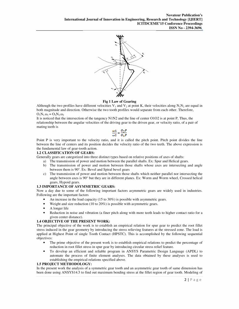
Fig 1 Law of Gearing
Although the two profiles have different velocities V1 and V2 at point K, their velocities along N1N2 are equal in
both magnitude and direction. Otherwise the two tooth profiles would separate from each other. Therefore,
O1N1.ω1 = O2N2.ω2
It is noticed that the intersection of the tangency N1N2 and the line of center O1O2 is at point P, Thus, the
relationship between the angular velocities of the driving gear to the driven gear, or velocity ratio, of a pair of
mating teeth is
=
Point P is very important to the velocity ratio, and it is called the pitch point. Pitch point divides the line
between the line of centers and its position decides the velocity ratio of the two teeth. The above expression is
the fundamental law of gear-tooth action.
1.2 CLASSIFICATION OF GEARS:
Generally gears are categorized into three distinct types based on relative positions of axes of shafts:
a) The transmission of power and motion between the parallel shafts. Ex: Spur and Helical gears.
b) The transmission of power and motion between those shafts whose axes are intersecting and angle
between them is 90°. Ex: Bevel and Spiral bevel gears
c) The transmission of power and motion between those shafts which neither parallel nor intersecting the
angle between axes is 90° but they are in different planes. Ex: Worm and Worm wheel, Crossed helical
gears, Hypoid gears.
1.3 IMPORTANCE OF ASYMMETRIC GEARS: Now a day due to some of the following important factors asymmetric gears are widely used in industries.
Following are the important factors
• An increase in the load capacity (15 to 30%) is possible with asymmetric gears.
• Weight and size reduction (10 to 20%) is possible with asymmetric gears.
• A longer life
• Reduction in noise and vibration (a finer pitch along with more teeth leads to higher contact ratio for a
given center distance).
1.4 OBJECTIVE OF THE PRESENT WORK: The principal objective of the work is to establish an empirical relation for spur gear to predict the root fillet
stress induced in the gear geometry by introducing the stress relieving features at the stressed zone. The load is
applied at Highest Point of single Tooth Contact (HPSTC). This is accomplished by the following sequential
objectives:
• The prime objective of the present work is to establish empirical relations to predict the percentage of
reduction in root fillet stress in spur gear by introducing circular stress relief feature.
• To develop an efficient and reliable program in ANSYS Parametric Design Language (APDL) to
automate the process of finite element analyses. The data obtained by these analyses is used to
establishing the empirical relations specified above.
1.5 PROJECT METHODOLOGY:
In the present work the analysis of a symmetric gear tooth and an asymmetric gear tooth of same dimension has
been done using ANSYS14.5 to find out maximum bending stress at the fillet region of gear tooth. Modeling of

Novateur Publication’s
International Journal of Innovation in Engineering, Research and Technology [IJIERT]
ICITDCEME’15 Conference Proceedings
ISSN No - 2394-3696
3 | P a g e
these gears has been done using 3-D modelling software Catia V5 R21 parametrically with the gear design
parameters as mentioned below. To model parametrically first the parameters have been collected or referred
from reference [11]. The parameters have been mentioned below in the chapter gear geometry.
ANALYTICAL METHOD
A spur gear with module 3.5 mm, number of teeth 24, pressure angle 20 degrees is considered for analysis and
also a asymmetric spur gear with 6mm module, number of teeth 30, pressure angle at drive side 25 degrees and
20 degrees for coast side is considered for analysis. Catia V5R20 software is used for geometry of gear teeth, the
location and size of the stress relieving features. The FEA results of root fillet stress without holes are compared
with the stress calculated using the gear root fillet stress with holes. The maximum principal stress is obtained
without any stress relieving features.
Fig2. Stress Analysis of Simple Spur Gear
Fig3. Analysis of Spur Gear with Hole at Root of Teeth
Fig4. Analysis of Gear with Hole at Centre of Tooth
Fig5. Analysis of Asymmetric Spur Gear
Fig6. Analysis of Asymmetric Spur Gear with Hole at Root of Tooth
Novateur Publication’s
International Journal of Innovation in Engineering, Research and Technology [IJIERT]
ICITDCEME’15 Conference Proceedings
ISSN No - 2394-3696
4 | P a g e
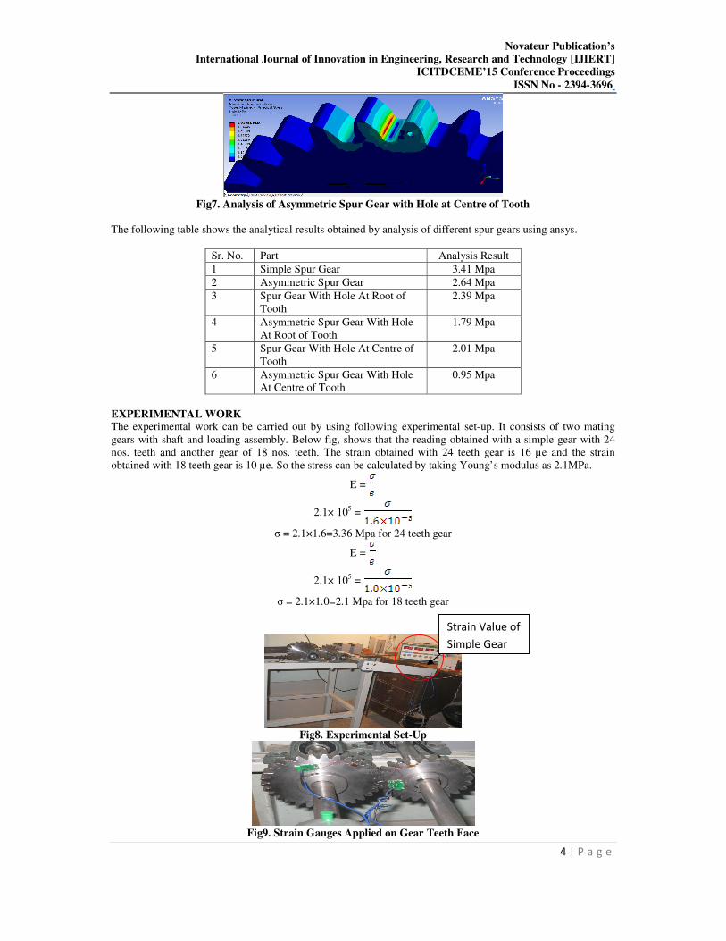
Fig7. Analysis of Asymmetric Spur Gear with Hole at Centre of Tooth
The following table shows the analytical results obtained by analysis of different spur gears using ansys.
Sr. No. Part Analysis Result
1 Simple Spur Gear 3.41 Mpa
2 Asymmetric Spur Gear 2.64 Mpa
3 Spur Gear With Hole At Root of
Tooth
2.39 Mpa
4 Asymmetric Spur Gear With Hole
At Root of Tooth
1.79 Mpa
5 Spur Gear With Hole At Centre of
Tooth
2.01 Mpa
6 Asymmetric Spur Gear With Hole
At Centre of Tooth
0.95 Mpa
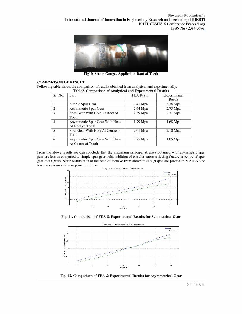
EXPERIMENTAL WORK The experimental work can be carried out by using following experimental set-up. It consists of two mating
gears with shaft and loading assembly. Below fig, shows that the reading obtained with a simple gear with 24
nos. teeth and another gear of 18 nos. teeth. The strain obtained with 24 teeth gear is 16 µe and the strain
obtained with 18 teeth gear is 10 µe. So the stress can be calculated by taking Young’s modulus as 2.1MPa.
E =
2.1× 105 =
σ = 2.1×1.6=3.36 Mpa for 24 teeth gear
E =
2.1× 105 =
σ = 2.1×1.0=2.1 Mpa for 18 teeth gear
Fig8. Experimental Set-Up
Fig9. Strain Gauges Applied on Gear Teeth Face
Strain Value of
Simple Gear
Novateur Publication’s
International Journal of Innovation in Engineering, Research and Technology [IJIERT]
ICITDCEME’15 Conference Proceedings
ISSN No - 2394-3696
5 | P a g e
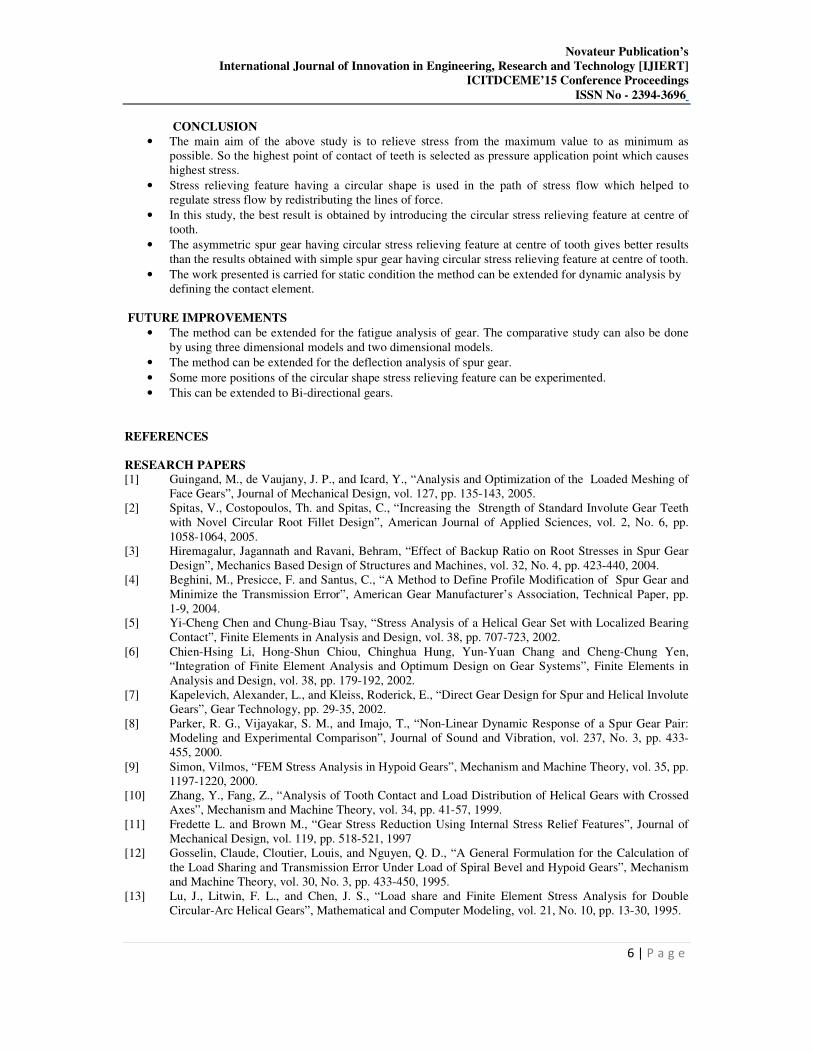
Fig10. Strain Gauges Applied on Root of Teeth
COMPARISON OF RESULT Following table shows the comparison of results obtained from analytical and experimentally.
Table2. Comparison of Analytical and Experimental Results
Sr. No. Part FEA Result Experimental
Result
1 Simple Spur Gear 3.41 Mpa 3.36 Mpa
2 Asymmetric Spur Gear 2.64 Mpa 2.73 Mpa
3 Spur Gear With Hole At Root of
Tooth
2.39 Mpa 2.31 Mpa
4 Asymmetric Spur Gear With Hole
At Root of Tooth
1.79 Mpa 1.68 Mpa
5 Spur Gear With Hole At Centre of
Tooth
2.01 Mpa 2.10 Mpa
6 Asymmetric Spur Gear With Hole
At Centre of Tooth
0.95 Mpa 1.05 Mpa
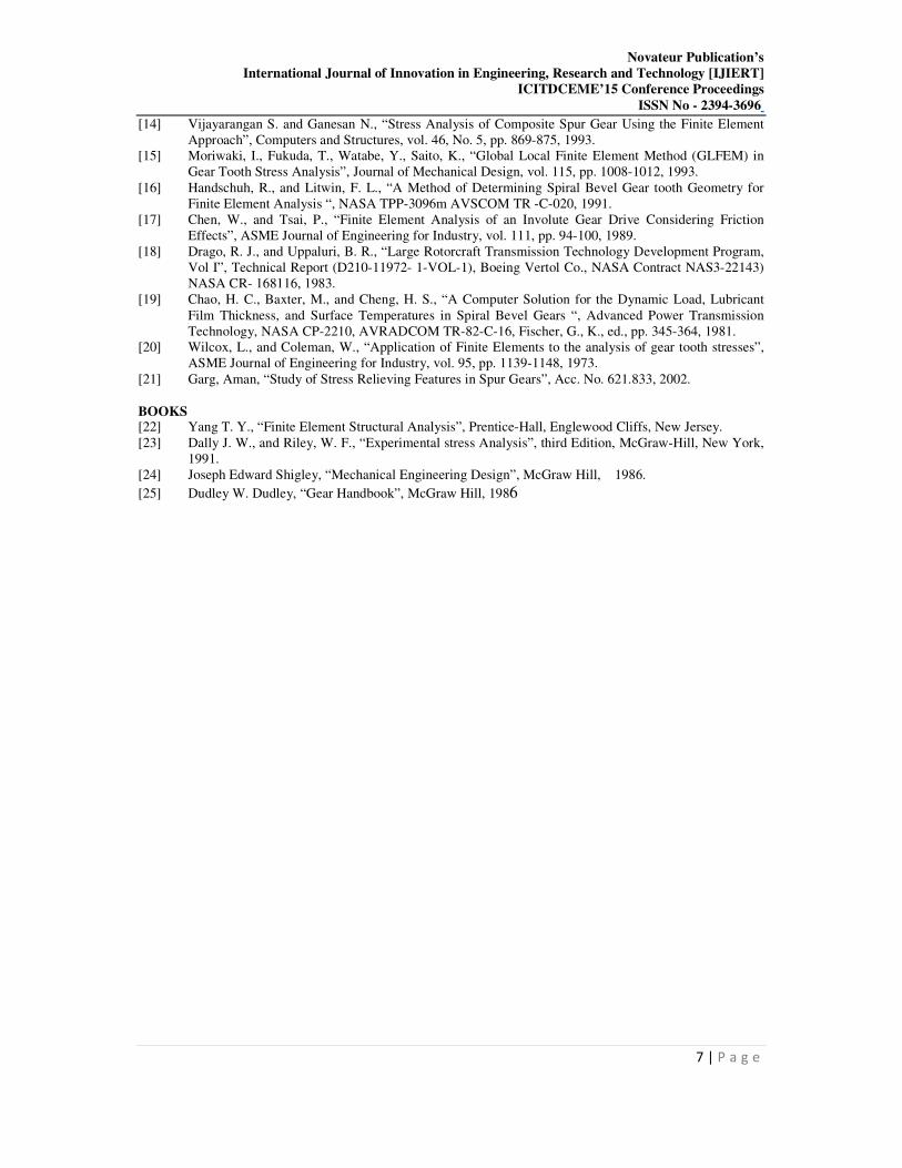
From the above results we can conclude that the maximum principal stresses obtained with asymmetric spur
gear are less as compared to simple spur gear. Also addition of circular stress relieving feature at centre of spur
gear tooth gives better results than at the base of teeth & from above results graphs are plotted in MATLAB of
force versus maxmimum principal stress.
Fig. 11. Comparison of FEA & Experimental Results for Symmetrical Gear
Fig. 12. Comparison of FEA & Experimental Results for Asymmetrical Gear
Novateur Publication’s
International Journal of Innovation in Engineering, Research and Technology [IJIERT]
ICITDCEME’15 Conference Proceedings
ISSN No - 2394-3696
6 | P a g e
CONCLUSION
• The main aim of the above study is to relieve stress from the maximum value to as minimum as
possible. So the highest point of contact of teeth is selected as pressure application point which causes
highest stress.
• Stress relieving feature having a circular shape is used in the path of stress flow which helped to
regulate stress flow by redistributing the lines of force.
• In this study, the best result is obtained by introducing the circular stress relieving feature at centre of
tooth.
• The asymmetric spur gear having circular stress relieving feature at centre of tooth gives better results
than the results obtained with simple spur gear having circular stress relieving feature at centre of tooth.
• The work presented is carried for static condition the method can be extended for dynamic analysis by
defining the contact element.
FUTURE IMPROVEMENTS
• The method can be extended for the fatigue analysis of gear. The comparative study can also be done
by using three dimensional models and two dimensional models.
• The method can be extended for the deflection analysis of spur gear.
• Some more positions of the circular shape stress relieving feature can be experimented.
• This can be extended to Bi-directional gears.
REFERENCES
RESEARCH PAPERS
[1] Guingand, M., de Vaujany, J. P., and Icard, Y., “Analysis and Optimization of the Loaded Meshing of
Face Gears”, Journal of Mechanical Design, vol. 127, pp. 135-143, 2005.
[2] Spitas, V., Costopoulos, Th. and Spitas, C., “Increasing the Strength of Standard Involute Gear Teeth
with Novel Circular Root Fillet Design”, American Journal of Applied Sciences, vol. 2, No. 6, pp.
1058-1064, 2005.
[3] Hiremagalur, Jagannath and Ravani, Behram, “Effect of Backup Ratio on Root Stresses in Spur Gear
Design”, Mechanics Based Design of Structures and Machines, vol. 32, No. 4, pp. 423-440, 2004.
[4] Beghini, M., Presicce, F. and Santus, C., “A Method to Define Profile Modification of Spur Gear and
Minimize the Transmission Error”, American Gear Manufacturer’s Association, Technical Paper, pp.
1-9, 2004.
[5] Yi-Cheng Chen and Chung-Biau Tsay, “Stress Analysis of a Helical Gear Set with Localized Bearing
Contact”, Finite Elements in Analysis and Design, vol. 38, pp. 707-723, 2002.
[6] Chien-Hsing Li, Hong-Shun Chiou, Chinghua Hung, Yun-Yuan Chang and Cheng-Chung Yen,
“Integration of Finite Element Analysis and Optimum Design on Gear Systems”, Finite Elements in
Analysis and Design, vol. 38, pp. 179-192, 2002.
[7] Kapelevich, Alexander, L., and Kleiss, Roderick, E., “Direct Gear Design for Spur and Helical Involute
Gears”, Gear Technology, pp. 29-35, 2002.
[8] Parker, R. G., Vijayakar, S. M., and Imajo, T., “Non-Linear Dynamic Response of a Spur Gear Pair:
Modeling and Experimental Comparison”, Journal of Sound and Vibration, vol. 237, No. 3, pp. 433-
455, 2000.
[9] Simon, Vilmos, “FEM Stress Analysis in Hypoid Gears”, Mechanism and Machine Theory, vol. 35, pp.
1197-1220, 2000.
[10] Zhang, Y., Fang, Z., “Analysis of Tooth Contact and Load Distribution of Helical Gears with Crossed
Axes”, Mechanism and Machine Theory, vol. 34, pp. 41-57, 1999.
[11] Fredette L. and Brown M., “Gear Stress Reduction Using Internal Stress Relief Features”, Journal of
Mechanical Design, vol. 119, pp. 518-521, 1997
[12] Gosselin, Claude, Cloutier, Louis, and Nguyen, Q. D., “A General Formulation for the Calculation of
the Load Sharing and Transmission Error Under Load of Spiral Bevel and Hypoid Gears”, Mechanism
and Machine Theory, vol. 30, No. 3, pp. 433-450, 1995.
[13] Lu, J., Litwin, F. L., and Chen, J. S., “Load share and Finite Element Stress Analysis for Double
Circular-Arc Helical Gears”, Mathematical and Computer Modeling, vol. 21, No. 10, pp. 13-30, 1995.
Novateur Publication’s
International Journal of Innovation in Engineering, Research and Technology [IJIERT]
ICITDCEME’15 Conference Proceedings
ISSN No - 2394-3696
7 | P a g e
[14] Vijayarangan S. and Ganesan N., “Stress Analysis of Composite Spur Gear Using the Finite Element
Approach”, Computers and Structures, vol. 46, No. 5, pp. 869-875, 1993.
[15] Moriwaki, I., Fukuda, T., Watabe, Y., Saito, K., “Global Local Finite Element Method (GLFEM) in
Gear Tooth Stress Analysis”, Journal of Mechanical Design, vol. 115, pp. 1008-1012, 1993.
[16] Handschuh, R., and Litwin, F. L., “A Method of Determining Spiral Bevel Gear tooth Geometry for
Finite Element Analysis “, NASA TPP-3096m AVSCOM TR -C-020, 1991.
[17] Chen, W., and Tsai, P., “Finite Element Analysis of an Involute Gear Drive Considering Friction
Effects”, ASME Journal of Engineering for Industry, vol. 111, pp. 94-100, 1989.
[18] Drago, R. J., and Uppaluri, B. R., “Large Rotorcraft Transmission Technology Development Program,
Vol I”, Technical Report (D210-11972- 1-VOL-1), Boeing Vertol Co., NASA Contract NAS3-22143)
NASA CR- 168116, 1983.
[19] Chao, H. C., Baxter, M., and Cheng, H. S., “A Computer Solution for the Dynamic Load, Lubricant
Film Thickness, and Surface Temperatures in Spiral Bevel Gears “, Advanced Power Transmission
Technology, NASA CP-2210, AVRADCOM TR-82-C-16, Fischer, G., K., ed., pp. 345-364, 1981.
[20] Wilcox, L., and Coleman, W., “Application of Finite Elements to the analysis of gear tooth stresses”,
ASME Journal of Engineering for Industry, vol. 95, pp. 1139-1148, 1973.
[21] Garg, Aman, “Study of Stress Relieving Features in Spur Gears”, Acc. No. 621.833, 2002.
BOOKS [22] Yang T. Y., “Finite Element Structural Analysis”, Prentice-Hall, Englewood Cliffs, New Jersey.
[23] Dally J. W., and Riley, W. F., “Experimental stress Analysis”, third Edition, McGraw-Hill, New York,
1991.
[24] Joseph Edward Shigley, “Mechanical Engineering Design”, McGraw Hill, 1986.
[25] Dudley W. Dudley, “Gear Handbook”, McGraw Hill, 1986