
Analysis of radiative heat transfer for large objects … · nasa c m 0 p n z i- 4 fa 4 z technical...
117
... NASA c m 0 P n z I- 4 fA 4 z TECHNICAL NOTE ANALYSIS OF RADIATIVE HEAT TRANSFER FOR LARGE OBJECTS AT METEORIC SPEEDS ). , ' ? I <.# .' by Kenneth K. Yosbikawa 1;' Ames Research Center * * Mofett Field, Calzy 4 , , + \ NATIONAL AERONAUTICS AND SPACE ADMINISTRATION WASHINGTON, D. C. JUNE 1967 https://ntrs.nasa.gov/search.jsp?R=19670019837 2018-07-28T15:54:07+00:00Z
Transcript of Analysis of radiative heat transfer for large objects … · nasa c m 0 p n z i- 4 fa 4 z technical...

...
NASA
c m 0 P n z I-
4 fA 4 z
TECHNICAL NOTE
ANALYSIS OF RADIATIVE HEAT TRANSFER FOR LARGE OBJECTS AT METEORIC SPEEDS
).
,' ? I < . # .' by Kenneth K. Yosbikawa 1 ; '
Ames Research Center * *
Mofett Field, Calzy
4, , + \
NATIONAL AERONAUTICS A N D SPACE A D M I N I S T R A T I O N W A S H I N G T O N , D. C. JUNE 1967
https://ntrs.nasa.gov/search.jsp?R=19670019837 2018-07-28T15:54:07+00:00Z

TECH LIBRARY KAFB, NM
I llllll 111111111111//1111111111111111 IIII 1111 0130770
NASA TN D-4051
ANALYSIS O F RADIATIVE HEAT TRANSFER FOR
LARGE OBJECTS AT METEORIC SPEEDS
By Kenneth K. Yoshikawa
A m e s R e s e a r c h Center Moffett Field, Calif.
NATIONAL AERONAUTICS AND SPACE ADMINISTRATION
For sale by the Clearinghouse for Federal Scientific and Technical Information Springfield, Virginia 22151 - CFSTI price $3.00

TABLE OF CONTENTS
SUMMARY . . . . . . . . . . . . . . . . . . . . . . . . . . . . . . . . 1
LNTRODUCTION . . . . . . . . . . . . . . . . . . . . . . . . . . . . . 1
SYMBOLS . . . . . . . . . . . . . . . . . . . . . . . . . . . . . . . . 2
ANALYSIS . . . . . . . . . . . . . . . . . . . . . . . . . Assumptions and Geometry . . . . . . . . . . . . . . . . Basic Radiative Equation . . . . . . . . . . . . . . . . Pseudo One-Dimensional F l o w Model and Thermal Function . Linearization of Radiative Transfer Equation . . . . . . Approximate Solutions f o r a Single Layer . . . . . . . . . . . . . . . . . . . . . . . . . . . . . . . . . Approximate Solutions f o r Optical ly Thin and Thick Layers . . . . . . . . . . . . . . .
Optical ly t h i n layers (Tw << 1) Optically th ick layers ('r, >>1) . . . . . . . . . . . . . . . . . . . . Optically t h i n layers (TW << 1) . . . . . . . . . . . Optically th ick layers (TW >>1) . . . . . . . . . .
Calculation of Boundary Conditions . . . . . . . . . . . Selection of Constants m and n . . . . . . . . . . . . . Conversion of Optical Thickness t o Physical Thickness . . Approximate Solutions f o r Multilayers . . . . . . . . . .
Absorption of radiat ion by the free-stream (preheating) Inject ion and ablat ion layers . . . . . . . . . . . . .
Plane shock flow (7 = 0) Stagnation streamline flow ( y = 1)
Plane shock flow ( y = 0 ) . . . . . . . . . . . Stagnation streamline f l o w ( y = 1)
. . . . . . . . . . . . . . . . . . . . . . . . . . . . . . . . . . . . . . . . . . . . . . . . . . . . . . . . . . . . . . . . . . . . . . . . . . . . . . . . . . . . . . . . . . . . . . . . . . . . . . . . . . . . . . . . . . . . . . . . . . . . . .
8 8 8 11 13 14 15 18 22 22 22 23 25 25 27 30 31 32 33 33 37
.RESULTS FOR A SINGU LAYER . . . . . . . . . . . . . . . . . . . . . . kl Comparisons With More Exact Analyses . . . . . . . . . . . . . . . . 41
Plane shock wave f l o w ( y = 0) . . . . . . . . . . . . . . . . . . . 41 Stagnation flow ( y = 1) . . . . . . . . . . . . . . . . . . . . . . 41
Radiative F l u Results . . . . . . . . . . . . . . . . . . . . . . . 42 Shock-Layer Prof i les . . . . . . . . . . . . . . . . . . . . . . . . 43 Shock Standoff Distance . . . . . . . . . . . . . . . . . . . . . . . 44
APPLICATIONS TO MULTILAYERS . . . . . . . . . . . . . . . . . . . . . . 45
Preheating Zone . . . . . . . . . . . . . . . . . . . . . . . . . . . 46 Blockage of Radiation by Injected or Ablated Vapors . . . . . . . . . 45
Effect of Nonadiabatic F l o w on Convective Heating . . . . . . . . . . 46
CONCLUDINGFUQWRKS . . . . . . . . . . . . . . . . . . . . . . . . . . 47
APPENDIX A . RADIATIVE TRANSPORT EQUATION IN DOUBLE OR MULTILAYERS 48 Equivalent W a l l Approximation . . . . . . . . . . . . . . . . . . . . 48 Equivalent Boundary Values . . . . . . . . . . . . . . . . . . . . . 51
i

Page
APPENDIXB.THERMALWCTION . . . . . . . . . . . . . . . . . . . . . Temperature-Pressure Relation . . . . . . . . . . . . . . . . . . . .
APPENDIX C . MODIFIED BESSEL FUNCTIONS OF THE FIRST AND SECOND KIND (I. K) . . . . . . . . . . . . . . . . . . . . . . . . .
Different ia t ion formula . . . . . . . . . . . . . . . . . . . . . . Recurrence r e l a t i o n . . . . . . . . . . . . . . . . . . . . . . . . ................. ( 0 ) Function . . . . . . . . . . . . . . . . . .
Integrals involving .. ( e ) functions . . . . . . . . . . . . . . . Integral ....... ( 0 ) function . . . . . . . . . . . . . . . . . .
APPENDIX D . EVALUATION OF BOUNDmY CONDITIONS . . . APPENDIX E . ASCENDING EXPANSION OF Z FUNCTION (TW <<1) . . . . . . APPENDIX F . ASYMPTOTIC EXPANSION OF THE Z FUNCTION (-rW >> 1) . . . .
Evaluation of I,. k(nTw) and K,. k(nTw) . . . . . . . . . . . . . . . Asymptotic Expans ion of C ,,. 8 ) . . . . . . . . . . . . . . . . . . Calculation of Radiative Flux Function r . . . . . . . . . . . . . .
APPENDIX G . CALCULATION OF RADIATIVE FLUX WITH PREKEATING INTEFACTION . . . . . . . . . . . . . . . . . . . . . .
APPENDIX H . CALCULATION OF RADIATIVE FLUX IN INJECTION AND ABLATION LAYEBS . . . . . . . . . . . . . . . . . . . .
Injection Layer . . . . . . . . . . . . . . . . . . . . . . . . . . . Ablation Layer . . . . . . . . . . . . . . . . . . . . . . . . . . .
APPENDIX I . EQUILIBRIUM AIR PROPERTIES . . . . . . . . . . . . . . . . REFERENCES . . . . . . . . . . . . . . . . . . . . . . . . . . . . . . TABLE . . . . . . . . . . . . . . . . . . . . . . . . . . . . . . . . . FIGURES . . . . . . . . . . . . . . . . . . . . . . . . . . . . . . . .
53 53
56 56 56 57 58 39
61
64
67 67 69 73
77
81 81 82
83
84
89
ii
I

ANALYSIS O F RADIATIVE HEAT TRANSjBR FOR
LARGE OBJECTS AT METEORIC SPEEDS
By Kenneth K. Yoshikawa
Ames Research Center
SUMMARY
An e x p l i c i t closed-form solut ion has been obtained f o r rad ia t ive heat t r ans fe r t o a body i n f l i g h t i n the ea r th ' s atmosphere a t speeds such t h a t radiat ion is t h e dominant mode of heat t r ans fe r . The solut ion w a s a t ta ined by assuming a gray-gas rad ia tor and then l inear iz ing the rad ia t ive t r ans fe r equation. which allow the solut ion t o be applied t o the stagnation region of a shock layer on an a x i s m e t r i c body. solution is readi ly applicable t o multi layer heat t r ans fe r encountered during very high speed f l i g h t s , when the interact ions among the cold a i r ahead of the shock wave, the heated air behind the shock wave, and the layer of ablat ion gases adjacent t o the body surface must be considered.
Approximations t o the one-dimensional flow equations are developed
Because of i t s charac te r i s t ics , t h e l inear ized
The development of the f i r s t -order l inear ized solution f o r rad ia t ive heat t r ans fe r i s described, and some appl icat ions a re presented and discussed. The results demonstrate t he e f f ec t s , on rad ia t ive and convective heat t r ans fe r t o the body surface, of shock-layer energy loss by radiat ion, absorption of rad ia t ion within the multiple layers , blockage of rad ia t ive heating by blowing of ab la t ive vapors, and the absorption and emission of rad ia t ion by the body.
INTRODUCTION
For atmospheric entry a t meteor ve loc i t i e s , radiat ion i s the dominant mode of energy t r ans fe r . Many invest igators have emphasized the importance of understanding and predicting the radiant heat t r ans fe r t o bodies a t these speeds (e.g. , r e f s . 1-3) . These invest igators have pointed out t h a t energy l o s s by radiat ion from the shock layer and t h e reabsorption of rad ia t ion i n the shock layer i t s e l f , i n t h e free stream, and i n ab la t ion products w i l l a f f ec t both the rad ia t ive and convective heat t r ans fe r t o the body.
Both simplifying flow assumptions and i n t r i c a t e numerical techniques have been used t o solve t h e gasdynamic problem. Examples of the flow assumptions t h a t have been used are: ve loc i ty d i s t r ibu t ion and constant pressure i n the shock layer ( ref . 5 ) . Reference 6 showed tha t t h e mass flow d i s t r ibu t ion on t h e stagnation stream- l i n e , ra ther than t h e ve loc i ty d is t r ibu t ion , is r e l a t i v e l y insens i t ive t o rad ia t ive heat t r ans fe r . Examples of numerical techniques a r e l o c a l s imi l a r i t y ( r e f . 7) and the in t eg ra l method ( ref . 8 ) .
one-dimensional porous flow (ref . 4) and a l i n e a r

Most invest igators have emphasized t h e e f f e c t s of rad ia t ion cooling ra ther than self-absorption on shock-layer s t ruc tu re . The inclusion of self- absorption in to the problem introduces addi t iona l complexities t h a t require fur ther s implif icat ion of e i t h e r t he equations o r t he forms of t h e i r solu- t i ons . These simplif icat ione generally involve t h e subs t i tu t ion of an expo- nent ia l function f o r t h e exponential i n t eg ra l that appears i n t h e solut ions of t he t r ans fe r equation, and/or t he use of successive approximations employing combinations of simple functions (refs. 9-13).
Subst i tut ing t h e exponential function is the simplest means of evaluating reentry radiat ion, including self-absorption, with reasonable accuracy.
A t r e l a t i v e l y high free-stream density, where t h e rad ia t ion mean free path i s comparable t o or smaller than the body s i ze , one can assume t h a t radi- a t ion flux is absorbed by t h e media j u s t ahead of t he shock f ront (preheating). The s t ruc ture of t he strong shock f ron t has been investigated (refs. 14-17) f o r plane shock flow of a perfect gas . thermal rad ia t ion e f f ec t s on the s t ruc ture of t h e shock wave ra ther than the influence of preheating energy on rad ia t ive heat ing.
Such analyses e x p l i c i t l y consider
The ab la t ive mass loss from large meteors enter ing the atmosphere w a s considered ( re f . 18) assuming a porous-flow analogy and the Rosseland approxi- mation. The increase i n t o t a l shock stand-off dis tance due t o a s izable amount of ab la t ion or in jec t ion has been shown, both theo re t i ca l ly and experi- mentally, t o obey a l i n e a r correlat ion formula (refs. 19 and 20); t h i s pro- vides a bas i s f o r calculat ing rad ia t ive in te rac t ion between shock and ablat ion layers .
O u r primary i n t e r e s t here i s t o obtain the simplest form of an ana ly t i ca l solut ion f o r rad ia t ive t r ans fe r i n t h e shock layer , especial ly exp l i c i t expressions f o r rad ia t ive net fluxes a t t h e body and a t the shock. This solu- t i o n includes t h e e f f ec t of self-absorption i n a strong shock layer , t h e in te rac t ion of thermal rad ia t ion with the shock layer , t h e preheating zone, and the ablated vapor layer . convective heating rates i n adiabat ic and nonadiabatic flow.
The results w i l l be used t o r e l a t e t he
SYMBOLS
an coef f ic ien t of series expansion (eqs. (15))
B
BV
Stefan-Boltzsnann function (eq. (2b ) ) or blowing parameter (eqs. (101b))
2h 9 Planck's function, - c2 ehv/kT - 1
Cv(0),C_,(e) indef in i te i n t eg ra l of modified Bessel function (eqs. 37)
C,,C-,
2
d e f i n i t e in tegra l of modified Bessel function (eqs. (38b))

cP
c 1,c2
En
F
F’ -
f
f W
I
k
Lo ,LbO
Lt
L V
M
specif ic heat a t constant pressure
constants associated with equation (26a)
exponential in tegra l function of order n (eq. (6) )
thermal function defined by equation (14)
auxi l ia ry function defined by equations ( 1 8 ~ )
pwvw pwvw
blowing rate, -
parameter defined by equations (101b)
a l t i t u d e
enthalpy
h enthalpy r a t i o , - hS
specif ic in tens i ty (eq. (1))
modified Bessel function of first kind (order v)
functions defined by equations ( 3 2 ~ ) and (38a)
modified Bessel function of second kind (order v)
constant associated with shock stand-off distance (eqs . (76)) o r the Boltzmnn constant
constant associated with blowing thickness (eq. (94) )
nonadiabatic shock stand-off distance and nonadiabatic blowing thickness
adiabat ic shock and blowing thickness
t o t a l shock-layer thickness
modified Struve function (eq. (C14a))
molecular weight
3
I

functions defined by equations (26)' (33), and (40) Mo ,Ml,M2 , M 3 ,M4 $5
m
n
0
P
P
qC
%O
s, R
R*
R+
r
T
Tef
TO - T
t
U
4
constant (1/2), mss, or power of pressure r a t i o
exponential constant
order of
pressure
pressure r a t i o , 2- PS
function defined i n equations ( 5 5 )
net rad ia t ive f lux
convective heat
convective heat with no rad ia t ion l o s s
adiabat ic rad ia t ive heat , 2pstts~Ts4LO
dimensionless boundary value (inward d i rec t ion is pos i t ive) (eqs . (8b) and ( c ) ) or body radius
q 2flB ( T f )
dimensionless boundary value based on Tf,
9 dimensionless boundary value based on Tsp, 2 , ~ ( T~~ )
r e f l e c t i v i t y
temperature
e f fec t ive surface temperature (eqs. (54a) and (b) )
surface temperature ahead of shock
temperature r a t i o , Ts
temperature r a t i o , uni ty or
temperature r a t i o
dummy variable
x component of ve loc i ty
T
T O - (eqs . (68) ) TS
T W 'T,

free-stream veloc i ty vm V
W
X
X
Y
Y
- a
Pl? P2
r
"S
Y
a 6
E
5
'1
'10
0
y component of veloci ty
Wronskian operator
l i n e a r solut ion defined by equation (26a)
dis tance along body
l i n e a r solut ion defined by equation (26a) or adiabat ic dis- tance (eq. (74a))
normal dis tance from shock t o w a l l
Bessel function defined by BVIv(n0) , 0%,(n0)
values of Bessel function defined by equations (38b)
constant defined by equations (Eb)
a P dF
average value of - (eq. (l3d))
cha rac t e r i s t i c constants (eqs. (28))
dimensionless rad ia t ive f lux function (eq. (8a)) or gamma function as designated
rad ia t ive f l u x absorbed by preheating zone (rsp - I?,)
constant t h a t characterizes flows (zero f o r plane shock flow, one f o r stagnation flow)
determinant (eqs. (33) and (40) )
boundary-layer thickness (eq. (103))
emissivity of boundary (eqs. (67))
heat of vaporization
var iable defined by equation (Flc)
quant i ty defined by equation (F3b)
independent var iable -rW - 7 (eqs . ( 1 8 ~ ) ) ~ angle of d i rec t iona l cosine, or apex angle
IC mss absorption coef f ic ien t (eq. (2a) )
5

h
A a
'b
V 0
P
P"
- 7
i 7
'wJ7wb
'w , 'wb
'w
cp
90
6
r a t i o of rad ia t ive heat t o t o t a l flow energy,
2 a~,* P,V,hs
r a t i o of black-body rad ia t ion lo s s t o t o t a l energy,
2 0 ~ ~ 4
P,vOohW
recurrence formula (eqs. (C14c))
4Ps"saTs4Lo ~ooVoohS
adiabat ic radiat ion l o s s parameter,
modified rad ia t ion lo s s parameter, C?) A,
di rec t ion cosine or viscos i ty
quant i ty defined by equation (F3b)
order of Bessel function (eq. (35b)), or frequency
parameter, KKLET,
dens it y
absorption coeff ic ient , cm-'
Stefan-Boltzmann constant
op t i ca l thickness defined by equation (2a)
T
op t i ca l thiclmess a t in te r face
op t i ca l thickness a t w a l l
r ad ia t ive blockage function a t wall (eq. (107))
rad ia t ive leakage function, - rw rSP
thermal function defined i n equations ( 1 8 ~ )
E u l e r ' s constant (0.37721 . . . ) + 2 Zn 2 (eqs. ( 5 5 ) )

x W
dimensionless mass flow r a t e , pv/pWvw (eqs . (u) )
absorption parameter (eq. (82))
Superscript
2 direct ion toward f r ee stream or downstream
1,II
* preheating zone, or l imit ing value of Bessel function
t modified function of dimensionless quant i t ies (dimensionless function
reference properties based on region I or region I1
based on temperature behind shock)
Subscript
b
e
f
i
2
P
0
r , r e f
S
6 1
SP
t
W
wo
Wp
00
blowing layer
edge of gas layer
j u s t ahead of shock wave, shock front
interface
l o c a l
preheating e f f ec t
adiabatic, no absorpt-m, no ablation, no preheating e f f ec t
reference condition
immediately behind the shock wave
sea l eve l
shock wave due t o preheating e f f ec t
t o t a l
w a l l
w a l l without preheating and inject ion
w a l l with preheating e f f ec t
f r ee stream
7

ANALYSIS
The equation of rad ia t ive transfer w i l l be combined with a simplified gasdynamic energy equation f o r one-dimensional flow, and the thermodynamic propert ies of a i r w i l l be introduced in such a way as t o make the resu l t ing equation l i n e a r . Solutions f o r t h i s linear equation w i l l be obtained fo r plane shock flow and stagnation stream-tube flows. The extension of t he tech- nique t o multiple gas layers (e.g., a zone of preheating o r of injected o r ablated species) w i l l be considered. t r ans fe r rates a t boundaries w i l l be emphasized. However, aux i l i a ry results, such as t h e d i s t r ibu t ion of enthalpy and temperature in t h e shock layer and the reduction of shock-layer thickness as a result of rad ia t ive t r ans fe r w i l l be obtained. possible. The notation used follows c lose ly t h a t of reference 2 o r of reference 21 with minor differences.
The calculat ion of rad ia t ive heat-
Details of t he analyses are deferred t o appendixes wherever
1.
2.
3.
4.
5 .
6 .
Assumptions and Geometry
The following assumptions are basic t o the analysis:
One-dimensional flow (plane shock flow and stagnation stream flow)
Local thermodynamic equilibrium
Gray-gas approximat ion
Viscosity and heat t r ans fe r by thermal conduction a r e neglected. ever, t he e f f e c t of rad ia t ion on convective heating w i l l be estimated i n a la ter sect ion.)
In the solut ion of t he t r ans fe r equation, t he exponential in tegra ls a r e replaced by exponential functions.
The term 'I@ a t h e r m 1 function i s defined which incorporates t h i s r e l a t ion ( loca l ly l i n e a r thermal r e l a t i o n ) .
(How-
i s assumed t o be l o c a l l y a l i n e a r function of enthalpy, and
Figures l ( a ) and l ( b ) show the geometry used i n the ana lys i s .
Basic Radiative Equation
If the absorption coef f ic ien t of t he gas is assumed t o be independent of frequency (gray gas) and the gas t o be i n local'thermodynamic equilibrium, t h e rad ia t ive t r ans fe r equation f o r plane p a r a l l e l flow i s
8

where is the specif ic in tens i ty ( r a t e of rad ia t ive energy flow per uni t area and so l id angle) , and is the d i rec t ion cosine r e l a t ive t o the f r ee stream (upstream di rec t ion i s pos i t ive) . The opt ica l thickness T and the Stefan-Boltzmann function B a r e defined by
I p
T = s,” PK dy
B =lm B, dv =
where B, is Planck’s function and IC, the mass absorption coeff ic ient .
The formal solution t o equation (1) is
J O
where I+ is the specif ic in tens i ty in the upstream direct ion (posi t ive p) and I- in the downstream direct ion (negative p); T~ is the opt ica l thickness a t the downstream boundary.
The r a t e of rad ia t ive energy
q - b ) =
q + ( d =
It follows t h a t
transport per u n i t area ( f i g . l ( b ) ) is

where ( r e f s . 9 and 22) is
q; = xI-(O), < = nI+(Tw), and the exponential in tegra l
- ~ / p n-2 En(T) s s,I e x d x
The net f l ux t ransferred per un i t area q is
If the dimensionless notations
r r(T) = q(T)/2d3s
5 = T / T ~
a r e introduced in to equation (71, we obtain
function En
(6 1
The subscript s r e f e r s t o posit ion immediately behind shock Wave. The first and second terms in equation (9a) represent t he radiat ive fluxes at the upstream and downstream boundaries, respectively, attenuated by the gas between T and the boundaries. The t h i r d and fourth terms represent the radiat ive fluxes a t T f romthe gas between T and the upstream and down- stream boundaries, respectively, attenuated by self-absorption. A t the
T from
upstream and downstream boundaries, equation (ga) reduces
-I-
t ) d t = Rw- rw
where E3 (0) = 1/2.
10

I
Equation (ga) is applicable t o multiple radiat ing and absorbing layers as w e l l as s ingle layers (e .g . , a preheating zone i n f ron t of a shock wave or a layer of injected or ablated gases from a sur face) . culat ion of fluxes i s complicated by the in te rac t ion between layers . To simplify the calculat ion an a p p r o x d t i o n is introduced whereby t h e ac tua l boundary fluxes are replaced by "equivalent w a l l " fluxes. concentrates t h e e f f e c t s of other layers a t t he boundaries of t h e layer f o r which the solut ion i s desired and allows equations ( 9 ) t o be applied t o each layer of t he multi layer separately. presented i n appendix A .
However, the exact cal-
This approximation
The d e t a i l s of t he procedure are
Pseudo One-Dimensional Flow Model and Thermal Function
In hypersonic flow, as the gas t r a v e l s downstream from the shock wave, i t s enthalpy decreases as a result of rad ia t ive l o s s t o t h e surroundings. Since t h i s study is concerned with f l i g h t conditions f o r which rad ia t ive heat- ing is the dominant mode of ene rgy t r ans fe r (e .g . , f o r a meteoric object entering the atmosphere), t he energy equation i n the shock layer may be wri t ten
p v d h = d q
where heat conduction and changes in t h e gas k ine t i c energy have been neglected. The mass flow along the stagnation streamline is expressed i n terms of op t i ca l thickness. F i r s t , we introduce the mass flow d i s t r ibu t ion
Many authors (e.g. , refs. 5, 13, 23) have assumed a l i n e a r r e l a t ion between mass flow d i s t r ibu t ion and physical thickness
where y is a constant (zero or one) t h a t character izes the flow. Flow with y = 0 corresponds t o plane shock f l o w such as i n shock tubes, piston problems, and porous type flows; flow with y = 1 corresponds t o stagnation streamline flow. For present purposes, it is convenient t o replace physical thickness in equation ( l l b ) with op t i ca l thickness. Thus, we assume i n t h i s paper t h a t
' Y x=@-+)
where y has the s a m e meaning as before. The v a l i d i t y of t h i s replacement is discussed in a later section, where it i s shown t h a t equation ( l l c ) is as good an approximation t o the ac tua l mass flow d i s t r ibu t ion as equation (llb) or b e t t e r . equation becomes
With t h e mass flow d i s t r ibu t ion of equation ( l l c ) t he energy
ll

I1 I I Ill1 I 1ll11l1l Ill Ill Ill II I1 Ill I
The thermodynamic var iables are now expressed by a dimensionless function (thermal function) F so that
or
1 Fs - F = - ~mVCu (hs - h ) = - (1 - h) 2dS4 A a
where Aa t o t a l flow energy.
i s the r a t i o of the black-body rad ia t ion a t the shock wave t o t h e
E = h/hs
After integrat ing t h i s las t equation constant densi ty) , one can r ead i ly obtain
f o r a constant pressure process (or ( ref . 4)
where
J e t c .
The var ia t ions of reference conditions.
h and F w i t h temperature are shown i n f igure 2 f o r two
It can be seen from f igure 2 t h a t t he temperature var ia t ion can be fur ther simplified f o r wide ranges of enthalpy as
T4 = 1 - a(Fs - F) 0 5 c 1 -
i f CL reference poin t . Thus,
i s taken from the average slope of (a;lff/aF) a t t h e designated
12

a = = Aa(g)av Appendix B gives a more de ta i led discussion of the thermal function.
From equations (13) and (12) the dimensionless thermal function is thus r e l a t ed t o the rad ia t ive function by
Linearization of Radiative Transfer Equation
The d i f f e r e n t i a l form of equations (9) is
Subst i tut ing equations ( l5c ) and (16) in to equation (l7), we obtain a l i n e a r in tegrodi f fe ren t ia l equation with a singular kernel
with an i n i t i a l value of
where
q = F s - F 1 N o attempt i s made t o f ind a general solut ion f o r equation (18a) except f o r y = 0, f o r which several numerical calculat ions have been car r ied out by a successive i t e r a t i o n method merely t o compare it with the approximate solut ion.

Approximate Solutions f o r a Single Layer
In t h e present paper-an approximate so lu t ion t o t h e t r ans fe r equation is given e x p l i c i t l y i n ana ly t ic and closed form when t h e exponential i n t eg ra l function E~(T) is replaced by an exponential function. W e introduce t h e commonly used approximat ion
where choice of m and n w i l l depend on the o p t i c a l thickness a t t h e w a l l ( T ~ ) of t h e plane layer , and w i l l be constant f o r given m and n are discussed l a t e r ; meanwhile, t h e solut ion i s car r ied out without assigning values t o these constants.
T ~ . The values of
It follows from equation (19) and the propert ies of t he exponential in tegra ls t h a t
The in tegra l equation (ga) then becomes
d t + m L T~ pe-n(t--r) d t -n(T-t)
- mn S,' p e -n ( T ~ - T ) r = - 2 m ~ ~ e - ~ ' + 2 m ~ s
After d i f f e ren t i a t ing the above equation twice, we obtain the following second-order nonlinear d i f f e r e n t i a l equation:
d? - + 2m - - n2r = o d2r dT2 dT
(Equation (22) is equivalent t o t h e Milne-Eddington approximation except with d i f f e ren t constants . ) becomes
From equation (16) the der ivat ive of t he temperature
With the simplified equations ( l l c ) and ( 1 3 ~ ) and t h e transformation
e = T W - - r

A l inear ized form of equation (22) is now obtained as
with boundary values, from equation (21),
rs = -2ms + 2mflVnTw
-nT rw = -2mRse w + 2 m R ,
J O
r T w -4 -n(TTt) - m T e d t
J O
(For consistency, E3(0) = m i s used instead of 1/2.)
The general solution of equation (25a) has the form
where c 1 and c2 a re constants and X and Y a r e functions t o be determined. In equation (26a) X and Y y = 0 a re the ordinary exponential functions, and for Y = 1, the modified Bessel functions. Solutions w i l l be obtained i n exp l i c i t and closed form for these two cases.
f o r
It w i l l be shown tha t the solutions of equation (25a) lead t o the fol- lowing important l i n e a r 1 re la t ions between the boundary values and the fluxes a t the boundaries:
Rs and Rw
- Expressions for the M functions w i l l be given i n terms of a and opt ica l thickness T ~ .
Plane shock flow ( y = O ) . - The d i f f e r e n t i a l equation (25a) fo r y = 0 become s
- .
%'his is a consequence of choosing a l i nea r thermal function (eq. ( l 5 c ) ) and does not require the exponential approximation (eq. (19)).
15
I

Its solution is
where
P 1 = G + J Z
p2 = -nm. +&ma)" + 1
Fluxes a t the boundaries a r e
To evaluate the constants equations (25b) and ( 2 5 ~ )
c 1 and c2, combine equations (29) w i t h
-nPaTw -mW 'W ?4,-nt c 1 + c2e = -2mS + -e d t
J O
where ('?)4 may be expressed in terms o f c 1 and cg by subst i tut ing equa- t ions (28) in to equation (16) and integrating between Thus, with equation ( L ~ c ) ,
0 and T .
Substi tuting equation (31) in to equations (30) gives two simultaneous algebraic equations f o r c 1 and cp of the form
y3c1 + K4c2 = KG
where
16
.. . .. - . . . . I

With some algebraic manipulation, equations (29) and (32) can be expressed i n the l i n e a r form:
- where the M values depend only on my n, a, and Tw, and are given by

The terms M, and & ditions; M1 and & wave (at T = 0); similarly, I'& and M5 show the e f f ec t s of re f lec t ion or emission a t T = T#.
a re fluxes from the shock layer without boundary con- show the e f f ec t s of re f lec t ion o r emission from the shock
For the present case, y = 0, it can be shown t h a t M1 = -M5.
Stagnation streamline flow ( 7 = .- 1) .- The d i f f e r e n t i a l equation (25a) f o r 7 = 1 becomes
which can be transformed t o the modified Bessel equation of order and 25); i t s general solution is
v ( r e f s . 24
r = ev[clI,,(ne) + c2K,,(ne)I ( 3% )
where respectively, and
I,, and K, a r e modified Bessel functions of the first and second kind,
Y = ItIIlET, + 1/2 ( 3% 1
18

The constants plane shock flow. of the Bessel functions required f o r the present analysis . )
c 1 and c2 are evaluated by a procedure similar t o t h a t f o r (Appendixes C and D give detai led evaluations of properties
where
By integration one obtains
Thus,
(374 where
Then K takes the following forms:

w * + - e Z-. -nT 1
2
K 5 = 2m ($ - RE) - 2me-nT(i - Rw)
where
V Z, r Z , ( T ~ ) = T~ I,(nT,
f z* - ’
where r ( v ) i n equations (38b) is a g a m function. Boundary fluxes are
rs = clzv + c2z
rw = c2zTV
-V
20

The re la t ion between fluxes and boundary values is again
rs = M, + MIRs + &Rw
where M now has the following forms:
Mo - - n m (. - e-nTw) [(& + & ) Z V - (Ki + .KS)Z-~]
The same physical interpretat ion can be ascribed t o these values of M a s t o those i n equations (33) . From equation (35a) it follows t h a t the f lux gradient a t the w a l l is
I rw = o
The enthalpy gradient a t the wall from equations (36) depends on v
21

where
The physical interpretat ion of t h i s dependence of enthalpy gradient on v w i l l be considered in a l a t e r sect ion.
Approximate Solutions for Optically Thin and Thick Layers
In t h i s section, t he solutions t o equations (26) a r e simplified fo r op t ica l ly t h i n and opt ica l ly thick shock layers . these simplifications a r e presented here. appendixes.
Only the major r e su l t s of Detai ls a r e presented in
Plane shock flow (7 = O). - The following a r e the r e su l t s fo r two l imit ing cases.
Optically t h i n layers (T by Taylor se r ies , the quant i t ies K
<< 1): If the exponentials a r e approximated w i n equations ( 3 2 ~ ) become, t o order TW2 ,
7 K1 = 1 + - 1 mt1GPlTw 2 2
t K5 2 -2m(Rs - Q) + mn(1 - 2RW)-rw
(43)
With the r e l a t ion derived from equations (28)
22
I 11111111

p 1 - p2 = 2nm (44)
The M values then d i r e c t l y follow from equations (33) and a r e \
Mi zi -2m + 0(-rw2)
J M5 =2m + O ( T , ~ )
The fluxes a t the boundaries f o r m = 1/2 and n = 2 are
rw 2 -[1 - (1 + &-,)TW]Tw - (1 - 2Tw)Rs + Rw ( 46b
Here, we have omitted second order terms f romthe boundary fluxes because, i n pract ice , Rs and R, w i l l usual ly be small. The choices of m and n will be j u s t i f i e d l a t e r .
Optically th ick layers ( - T ~ >>1): For l a rge op t i ca l thickness, K takes K1 t he following forms ( the second and t h i r d i d e n t i t i e s f o r
eqs. (28) ) : follow from I K i zz 1 + s P i / ( l + Pi) = K4 2 (1/2)(1 + Pi)
K2 zz (1 /2) (1 - P2)e
Ke3 = -E
K 4
K5 " m ( 1 - 2Rs)
-np27,
1 + "/(1 + P 2 ) 1
KG = - m ( l - 2%)
(47)
23

The determinant A becomes
A (1 + P d 2
N e t f luxes a t both boundaries
2m 1 + P 1
r = S
J
from equations (26) a r e
Flux var ia t ion and temperature var ia t ion f o r 1 << T << T~ a r e
-n P 17 r - 2m (1 - 2Rs)e 1 + P 1
The gas temperature a t the w a l l ( T = T~ >> 1) i s
Effective surface temperatures t h a t emit equivalent radiant f luxes from both boundaries are
( 54a )
= (2rw)1’4Ts (54b 1
1 / 4 ( T e f ) s = (2 r s ) TS
24

It i s noted from equations (3Ob) and (53) that radiant f lux toward t h e wall f o r an op t i ca l ly th ick layer with no boundary e f f ec t is always grea te r than t h e l o c a l black-body rad ia t ion a t the edge of t h e l aye r . i n references 4 anif 12.
This w a s a l s o shown
Stagnation streamline flow (7 = 1).- Appendixes E and F give d e t a i l s of t h e derivations f o r t i o n of t he Bessel functions becomes complicated. results.
T~ << 1 and Tw >> 1, respectively, since t h e manipula- The following a r e ' t h e
Optically t h i n l aye r s ( T ~ << 1) : For v = [ (1/2) + mn%-w] f ixed and t h e argument of t h e Bessel functions approaching zero, t he values of equations (38a) are
K i n
7
K5 -2m(Rs - R,) f mn(1 - 2 R w ) ~ w
K6 e -2m(Rs - R,) - mn(1 - 2RS)Tw
A nTw2(1 - 2mnE'P0~w)Q1"s,
where
= 2 2n 2 + 0.57721 (where second term i s E u l e r ' . s 'PO
vo = mnETW
1 -2( 1-v> 1- v Q1 = (:) r(v) Tw
a, = 1 2 n (2)1-vr(l - v) J I

r( v) and r(l - v) i n equations (55b) are gamma functions. are
The values of M
J ~5 = 2m11 - o(T,~)]
The boundary fluxes for m = 1/2 and n = 2 are
The thermal function i s
which, t o order T ~ , can be fur ther simplified as
From equation (141, and l e t t i n g p ro f i l e within the layer becomes
Rs = Q = 0 i n equation (58b) the enthalpy
which i s similar t o t he expression i n equation (15) of reference 23 for TW << 1.
26

The temperature d is t r ibu t ion follows d i r e c t l y from equation ( l5c)
which i s equivalent t o t h a t of reference 5 f o r T~ <<1.
It is interest ing t h a t t he boundary fluxes f o r plane shock flow (eqs . (46) ) and stagnation flow (eqs. (57) ) d i f f e r on ly i n second order of TW . f o r TW << 1.
Optically thick layers ( T ~ >> 1): Asymptotic expressions f o r K and M are :
. 1
K 1 = p (1 + P d Z ,
27

I
-4m 1 + P 1
Mi E
1 - Pa
1 +&E ~4 z -4m
4m 1 + &
M5 2
Thus, t h e boundary fluxes are
A s noted from equations (62) and (49), f luxes with no boundary e f f e c t s and &,) are near ly independent of t h e constant weakly dependent on n ) . t i o n comes f romthe constant m. Note t h a t t he asymptotic values of rw f o r stagnation flow decrease inversely as t h e square root of T~ whereas rw f o r plane shock flow reaches f in i te asymptotic values.
(M, i n eqs. (62) is very n (&
The major contributing f ac to r t o t h e f l u x calcula-
Asymptotic radiant f lux var ia t ions f o r 1 << 7 << Tw are
28

I
and the thermal function becomes
Fs - F 2 %(l - 2Rs) 1 - - - 1I : "XY 2 Final ly , the temperature d i s t r ibu t ion i s wri t ten
F4 -u 1 - Mo(l - 2Rs)a -[ 1 - - 7e" "Zyt"']
The asymptotic values of t he radiant functions above y ie ld ident ica l results t o those f o r propert ies are independent of ve loc i ty p r o f i l e f o r 1 << T << Tw.
y = 0 which shows t h a t t h e asymptotic values of radiant
2 For an op t i ca l ly th ick layer , the Rosseland approximation of ne t f l u x
is
Applying t h i s equation t o equation (66), we obtain
which d i f f e r s from (2/3)nPlE. If the
equation (64) when conibined with equation (63a) by a fac tor Rosseland approximation is t o apply, higher der ivat ives of - temperature d i s t r ibu t ion m u s t vanish, o r nP1 << 1. Since a i s a f i n i t e
constant, it is required t h a t (2/3)(nPl)E << 1. coeff ic ien t ( n P l ) h cannot be unity, i n f a c t , P 1 2 1; consequently, t h e Rosseland approximation f o r a high enthalpy flow f i e l d with radiat ion, i n general, is not applicable. This a l s o implies t h a t agreement with Rosseland approximation fo r an op t i ca l ly th ick layer in a flow f i e l d is not a property of t he asymptotic solut ion ( t h i s approximation can be commonly used f o r non- flow cases) and it may sometimes lead t o incorrect solut ions i f proper care is not exercised.
Now it is obvious t h a t t he

Ill1 I1 IIIII I I I
Calculation of Boundary Conditions
Boundary values r e f l e c t i v i t y of boundaries since the boundary values introduced i n equations (8b) and (c ) can be written3
Rs and Rw may be expressed in terms of emissivity and
4 + 9; = + 'Sqs + (external f luxes from upstream)
1 f lux ref lected from shock wave
4 q+ = EW'JTW + r w q , + (external f luxes from the wall) W
[flmwa;;orn] [flux reflected1 from w a l l J
In dimensionless form, equations (67a) and (b) may be writ ten ( fo r no external f luxes )
R s - % - 4 - 7 T s + rsrs+
cw - 4 + r r- 2 w w Rw = - Tw
- - where Ts = To/Ts and Tw = Tw/Ts. From equations (9) and (26) it follows t h a t
r i = M~ + (1 + M = ) R ~ + M ~ R , (694
Combining equations (68a) and (b) with equations (6ga) and (b) gives
- 1 { 11 - r,(2m - M 5 ) I E ~ T , - 4 + rsM,~,TW43 + rs{ [I - rw(2m - M 5 ) 1% - rwM2&] - - - . . . . . - . . . . . . . . . . ~ ~
- 2
{I1 - rs(2m + M d 1 1 1 - rw(2m - M 5 ) 1 + rsrwM2M4} R s -
. _ _ - - - . - - - . - ._ -
3Radiative f lux will be reflected-back in to the shock layer , f o r example, just pr ior t o an impact. the shock can be t rea ted s imilar ly .
Radiative f lux from a surface placed ju s t ahead of

Boundary temperatures t h a t they could include fluxes impinging from external sources added independently from the system.
To and Tw may be taken as ef fec t ive temperatures so
Selection of Constants m and n
Replacing the exponential i n t eg ra l function by an exponential function is e s sen t i a l t o t h e present analysis and i s comonly used as an ana ly t ic approximation f o r rad ia t ive t r ans fe r problems. Here the r e l a t ion
-n-r E3(7) = me
i s introduced where m and n are constants chosen i n some plausible fashion.
Although many d i f f e ren t values f o r m and n are found i n t he l i t e r a t u r e , depending on the appl icat ions, the first constant, m, i s not a rb i t ra ry ; it m u s t be 1/2 t o s a t i s f y the asymptotic solut ions f o r both op t i ca l ly t h i n and th ick layers . This is c l ea r f o r op t i ca l ly t h i n layers since
(71) 1 Ea(0) = m = - 2
For op t i ca l ly th ick layers , m must a l s o be 1/2, as w i l l be shown i n Results and Discussion where exact and approximate solutions of t he equations are compared. The exponential constant n i s l e s s r e s t r i c t ed , and proposed values of n between 3/2 and 2 are found i n the l i t e r a t u r e . The value 3/2 is associated with Eddington's approximation and has been preferred f o r as t ro- physical problems (ref . 21) . In t h i s paper, values of n which depend on t o t a l op t i ca l thickness op t i ca l ly t h i n and th i ck layers . The c r i t e r i o n is chosen t o match the area under E3 with the area under the exponential function:
-rW are used t o provide correct results f o r both
o r s TW s," 0
E3(T)dT = m
~~
4 Q ~ i ~ k convergence results i f equation (72) is rearranged as 6 = e-n'w - 1 + 2n[( l /3) - E ~ ( T ~ ) ] and solved f o r E: = 0.
I

Ill I l l I I I I II I
Thus, f o r Tw + 03, &(Tw) + 0, and n = 3/2 when m = 1/2. For TW + 0 , -EA(O) = E2(O) = an and n = 2 is tabulated in t a b l e I f o r various values of Tw and f o r m = 1/2.
when m = 1/2. A set of exponential constants
This completes t h e solut ion of t h e rad ia t ive t r ans fe r equation i n terms of op t i ca l thickness .
Conversion of Optical Thickness t o Physical Thickness
To f a c i l i t a t e appl icat ion of t h e solut ion t o physical problems t h e op t i ca l thickness m u s t be converted t o physical thickness. i n t o the shock layer is r e l a t ed t o op t i ca l depth by
Physical dis tance
dy = d T / p ( 73a 1
Integrat ing equation (73a) between 0 and -rW distance L as
gives the nonadiabatic standoff
For stagnation in to the shock
Therefore, t h e
From equations distance i s
An approximate ( ref . 3 ) is
32
flow, Goulard ( ref . 5) has shown t h a t t he nonadiabatic distance layer, y, is re la ted t o the adiabat ic dis tance Y by
adiabat ic standoff dis tance Lo i s
(73a) and (74a) t h e r a t i o of nonadiabatic t o adiabat ic standoff
re la t ion between adiabat ic dis tance and op t i ca l thickness
d(Y/Lo) E d(T/TW) = dy ( 75b 1

Incorporating t h i s approximation in to equation (75a) gives the following simple expression fo r standoff dis tance, which i s consistent with t h e present approximation f o r mass flow, equation ( I ~ c ) .
In order t o use equations (74b) and (75c) t h e densi ty r a t i o (p/ps) and absorption coef f ic ien t (PIC) can be expressed i n terms of power s e r i e s of enthalpy r a t i o (ref. 26), and t h e shock-layer thickness readi ly evaluated by numerical calculat ion. Finally, t he Hayes-Probstein formula relates Lo t o body radius and densi ty r a t i o across the normal shock wave (ref. 27) by
where
and an average value is
k = 3 f o r - Ps 2 16 4
(See a l s o r e f . 28.)
Approximate Solutions f o r Multilayers
Absorption of rad ia t ion by the free-stream (preheating).- If appreciable amounts of radiat ion are absorbed by the free-stream media just ahead of t he strong shock f ront , there i s an important e f f ec t on the s t ruc ture of t he shock layer and the rad ia t ive heating t o the body is changed s igni f icant ly . (Emission e f f ec t from upstream is somewhat similar t o increasing the ref lec- t i v i t y of t he shock f r o n t . ) Following references 16 and 29 t h e present paper assumes negl igible change i n k ine t i c energy and near ly constant densi ty ahead of t h e shock wave5 (as opposed t o near ly constant pressure i n t h e shock layer ) ; t he thermal function f o r a i r i n the preheating zone is therefore determined by a constant densi ty process. Furthermore, t he flow i n f ron t of t h e shock wave is planar and t h e analysis previously presented f o r y = 0 can be applied t o the preheating region. approximation (appendix A ) f o r t h e boundary conditions a t the shock wave, t h e flow can be separated in to two regions with var iable boundary conditions:
Therefore, with the "equivalent w a l l "
5 These assumptions are considered i n more d e t a i l in reference 29.
33

Region * is the preheated free stream with p -" p, (constant) and 7 = 0. Region I is t h e shock layer with p = ps (constant) and 7 = 1.
In the preheating zone, t he energy equation i s
where q* is the ne t radiant heat f lux i n t h e preheating zone and 9, is t h e radiant heat f l ux escaping from the zone (sketch ( a ) ) . Physically, t h i s model
TaT*O T Tw
Preheating Shack wave Wall edge
Sketch (a) Preheating and shock layer .
is adopted because, in real air , only the far u l t r av io l e t portion of t h e f l u x leaving t h e shock wave w i l l be absorbed in the free stream near t h e shock layer . Consequently, i n the present analysis t he portion of t he rad ia t ion leaving the shock f ront (G) is allowed t o escape f romthe system. pute parameter in the analysis .
No attempt i s made t o com- Q, but it simply becomes a
In the shock layer t he energy equation may be wri t ten from equation (10) as
= d(qsp - S) (78)
where qsp Equation (78) shows t h a t preheating changes t h e enthalpy l e v e l in the shock layer. This increase i s proportional t o (q SP - b) since energy balance a t t he shock wave ( y = 0) is
is t h e ne t rad ia t ive heating a t the shock wave due t o preheating.
which can be rewri t ten as
since
Thus, t he increases in enthalpy immediately ahead and behind the shock are obtained.
From equations (78) and (79a) three types of energy prof i les can be established.
34

Case (a) is f o r no preheating and i s the case previously discussed. is f o r i n f i n i t e layers t h a t reach adiabatic equilibrium Rankine-Hugoniot temperature as contains strong absorption, or a preheating e f f ec t and w i l l be discussed here. In dimensionless form equation (79a) becomes
Case (b)
T~ + 03 ( fo r 1 << T << T ~ ) . Case ( c ) is a general one, and
- F, -u rsp - r 00 (79b)
where r,, = qsp/2fiBs. From equation ( l5c ) , the corresponding temperature r i s e behlnd the shock wave is
Temperature i n the preheating zone is usually r e l a t ive ly small compared t o tha t i n the shock layer; thus emission from t h i s zone may be neglected. (An extension of t h i s par t of the analysis which includes emission from the preheating zone is given i n appendix G . ) With t h i s assumption and fur ther assuming negligible w a l l emission (Rs = Rw = 01, we have, f o r given from equation (26b)
TW and a,
-4 where shock wave due t o preheating. wall is
Tsp must be inserted t o account fo r the higher temperature behind the Similarly, from equation ( 2 6 ~ ) , the flux a t the
-4 rwp =
We now define
Combining t h i s def in i t ion with equations (80) and (81) gives
35

Since emission in the preheating zone has been neglected, the t ransfer equa- t i o n (9) i n t h i s zone takes on the pa r t i cu la r ly simple form
I?* = rsP2E3(T*) (84)
We use equation (84) t o define 7, so t h a t 7, = T* when Y* = roo. Hence
and 7, is fixed by through the r e l a t ion
(86) 1 E3(7,) = - (1 - 0) 2
Finally, the enthalpy d is t r ibu t ion i n the preheating zone (from eq. (77)) is
which a t the shock f ront becomes
where hf i s enthalpy immediately ahead of the shock. Pressure and tempera- t u r e i n t h i s zone a re now obtained d i r e c t l y from the thermodynamic chart f o r constant density (p* = p,) . The d is t r ibu t ion of thermal properties i n the shock layer with preheating may be found by adjusting the thermal function previously found (eqs. (14) and (1%)) t o account f o r the higher temperature due t o preheating immediately behind the shock wave. If the normalization temperature f o r t he thermal function F and the function I' is changed from Ts t o TSp9 then the previous analysis of the shock layer , equations (35) and (371, may be applied d i r ec t ly . Therefore we define a new thermal function i n the shock layer, Ft , normalized with respect t o GP by fl = F/Cp, or
This new thermal function i s re la ted t o the or ig ina l thermal function (without preheating) by
Fs - F
Fs - F = (F, - Fsp) + (Fsp - F)
-4 = -(rsp - r,) + T ~ ~ ( F ~ ~ -

.. . .. ... .. . .. _._.
The enthalpy and temperature d is t r ibu t ions in the shock layer obtained in a similar manner are
h = l + Aa[(rsp - F;p(Fsp -
Inject ion and ab la t ion layers . - It is assumed t h a t a secondary layer of vapor iza t ionmater ia l s from the w a l l is separated from t h e primary shock layer by an in te r face . and 3 0 ) . a t the in te r face . The analysis of the vaporization layer i s similar t o t h e analysis f o r a shock layer in t h a t constant pressure with flow) i s assumed. A s in t h e shock layer, it is assumed t h a t t he thermal prop- ert ies i n t h e vaporization layer can be correlated by a l i n e a r equation relat- ing T4 and enthalpy. The reference temperature for t h i s correlat ion is taken as the temperature of t he vapor a t t he w a l l . It is fur ther assumed t h a t t he injected gases a r e r e l a t i v e l y cool compared t o the a i r i n t h e shock layer; therefore, the emission from the injected vapors may be neglected. An exten- s ion of t h e analysis i n which t h i s las t assumption is relaxed is presented i n appendix H .
Experimental observations support t h i s assumption (refs. 20 Figure 1 indicates t h e geometry with a stagnation point i n the flow
y = 1 (stagnation
W e define a rad ia t ive blockage function as
where rwb is rad ia t ive flux penetrating t o t he w a l l through the vapor layer and rwo i s the rad ia t ive f l u x f o r t he same f l i g h t conditions without a vapor layer but, for consistency, with the s a m e w a l l temperature with and without vaporization.
The op t i ca l thickness of the vapor layer is measured from the w a l l t o t h e interface and conditions i n t h e vapor layer are denoted by the subscript b . Thus, Tb = 0 a t the W a l l and layer a t t h e in te r face .
Twb is the op t i ca l thickness of t h e vapor
If t h e emission f romthe vapor layer is assumed t o be smll compared t o t h e emission f romthe shock layer , it follows t h a t t he propert ies in t h e shock layer are not changed s ign i f i can t ly by the presence of t he vapor l aye r . Therefore, from equations (9),
Cons e quently , ( 9 3 )
37

The physical thiclmess of the vapor layer depends on the mass flow r a t e of t he vapors; i n adiabat ic flow the thickness of the vapor layer is correlated by a simple expression ( r e f s . 20 and 31) .
where kb -N 1 for a spherical nose ( r e f . 20); M, and b$, of air and vapor layers; Lo and h0
$ = Lo +bo.) or the t o t a l distance between shock wave and wall ; a r e the molecular weights
a r e the thicknesses of air and vapor layers f o r adiabatic flow; pb and fw is the blowing r a t i o
The correlat ion l a w (eq. vapor layer thickness and the
is the densi ty of the injected gas a t the w a l l ; ( %vb/p,vw)
(94)) fur ther provides a simple re la t ion between blowing parameter; thus,
where ks 0.75 for spherical noses (see eqs. (76)) and R i s the radius of the spherical body. The nonadiabatic thickness of the vaporization layer is approximated by equations (74b) and (75c) i n a manner similar t o the calculation of nonadiabatic shock-layer distance.
For forced inject ion of vapors from the surface, the blowing r a t e param- e t e r f w is given a p r i o r i and the solution i s then straightforward. For ablation, however, the blowing r a t e parameter depends on the heat reach- ing the w a l l rwb, and the solution i s therefore coupled. We assume t h a t the mass loss rate of ablat ion vapors per u n i t area i s given by
fw
where ( i s the heat capacity of ablat ion products. The net radiant heat through the en t i r e system a t the wall is
thus, the blowing parameter, fw = pbvb/&V,, becomes $i

where A, = ( ~ O - T ~ ~ / ~ V & ~ ) as i n equation (14). The coef f ic ien t Ub i n the thermal function f o r t he ablat ion layer is coupled with the blowing parameter fw, since rwb in equation (9) depends on % fo r given op t i ca l thiclmess and boundary conditions as given below:
where
and
With equations ( 9 5 ) , (@), and ( 9 9 ) and the solutions previously pre- 7 = 1, including equation (74b), an i t e r a t i v e procedure i s used
and f w and t h e ab la t ion vapor-layer thickness Lbo (see rwb
sented f o r t o determine appendix H ) .
A simpler and useful approximation for Owb may be obtained i f it i s fur ther assumed t h a t t h e absorption coeff ic ient ( %Kb) in the ablat ion layer is constant and t h a t t he blowing parameter fw i s very small.
Then, by the de f in i t i on of op t i ca l depth,
where Lb rewri t ten as
is nonadiabatic vapor layer thickness, equation (100) may be
where
39

(lOlb )
With equation (93), % becomes
From equations (97) and (98) and by the def in i t ion of @"b can be wri t ten
B i n equations ( lo lb) ,
'wb - - h, 'B
Equations (102) and (103) may be combined t o eliminate obtain h b (or vice versa) fo r ablat ion. For B << 1 (small ab la t ion) , equation (102) may be expanded i n the first order of power ser ies and combined with equation (103) t o obtain the approximate formula
B and therefore t o
where n has been s e t equal t o 2 and = 1. Equation (104) i s useful i n t h a t the absorption coeff ic ients of the shock layer and vapor layer (which a r e generally unknown) a re combined in to a r a t i o . s tudies for assessing the e f fec ts of rad ia t ive blockage.
This allows parametric
RESULTS FOR A SINGLE LAYER
Calculations of radiat ive f lux a t the boundaries and of prof i les of radiat ive flux, enthalpy, and temperature i n the shock layer have been made f o r selected f l i g h t conditions. these calculations a r e given i n appendix I. The r e su l t s a re used t o assess the e f fec t of rad ia t ive energy loss on shock standoff distance, the e f f ec t of preheating and absorption i n ablat ion layers on the radiat ive heat t ransfer
The equilibrium air properties used in making

t o t he body, and the e f f ec t of rad ia t ive energy loss on the convective heat transfer. results are considered by making comparisons w i t h other solut ions.
Where possible, t h e e f f e c t s of t he assumptions on the present
Comparisons With More Exact Analyses
Plane shock w a v e l o w (7 = O ) . - To evaluate the e r r o r intrcduced i n the present solutions by replacing the exponential in tegra ls with exponential functions, equation (185~) ( the in tegrodi f fe ren t ia l equation) was solved numericall? and t h i s solut ion compared with solut ions of equation (23a) ( the d i f f e r e n t i a l equation obtained by using the exponential approximation). Various commonly used values of t he constants calculat ions. The results are shown in f igure 3(a) f o r 7 = 0, where rw and rs, t he rad ia t ive heat t o the w a l l and free stream, respectively, are p lo t ted as functions of T ~ . This f igure shows t h a t t h e exact and approximate solu- t i ons agree w e l l f o r m = 1/2 and n varying from 3/2 t o 2 (but constant fo r a given value of analysis, m i s not a r b i t r a r y but should be 1/2 as required by the asymptotic values f o r op t i ca l ly t h i n and th ick layers and by the equivalent wall approx- imation. This becomes pa r t i cu la r ly apparent ( f i g . 3(a)) f o r rs as opt ica l thickness is increased since the r e s u l t s f o r values of m d i f f e ren t from 1/2 deviate from the correct asymptotic f lux. The other constant n is less r e s t r i c t ed , excep t , t ha t it should take on the value of 2 as rw approaches zero because it m u s t take t i o n f o r t i o n except, as expected, f o r s m a l l op t i ca l thickness.
m and n were used in these
T ~ ) as provided by equation (72) . A s mentioned i n t he
mn = 1 f o r Tw + 0 . Note t h a t the approximate solu- m = l / 2 and n = 3/2 shows r a the r good agreement with the exact solu-
Stagnation _ ~ _ _ _ flow (7 = 1).- A comparison similar t o t h a t of f igure 3(a) but fo r y = 1 has not been made pr imari ly because of numerical d i f f i c u l t i e s associated with the s ingu la r i t i e s i n equation (18a). Viegas' ( r e f . 7) elaborate viscous solut ions a r e avai lable f o r comparison with t h e present solut ion. They do not assume a l i n e a r thermal function, a l i n e a r mass flow re la t ion , o r t h e exponential approximation (as does the present work). absorption coef f ic ien ts as used i n the present work. Furthermore, t he solu- t i ons of reference 7 are fo r r e l a t i v e l y small values of T~ and thus energy lo s s by radiat ion i s emphasized ra ther than energy red is t r ibu t ion by self- absorption. agreement between the two treatments except, of course, near t he wall where viscous e f f ec t s predominate. The approximate boundary-layer edge, 6 , is indicated i n f igure 3(b) as estimated from the empirical equation ( re f . 32) as
However, Howe and
However, t h e i r solut ions are f o r a gray gas, w i t h t h e same
The comparison i s presented in f igure 3(b) which shows very good
./ 2PS(dU/dx)O - .- - - - - . . - . - . ____ . .
6In t h e i t e r a t i o n process f o r equation (18;) t h e approx&te solut ion i s subst i tuted as an i n i t i a l input function. This reduces t h e d i f f i c u l t y of con- vergence associated with t h e equation and is very e f fec t ive i n control l ing osc i l l a t ions of t h e solut ion.
41

The stagnation streamline mass-flow d is t r ibu t ion used i n the present work is shown i n f igure 3 ( c ) . The calculated mass-flow d is t r ibu t ions f o r various opt ica l thicknesses a r e plot ted as a function of physical depth in to the shock layer and a r e compared with both a l i n e a r equation and the more r e a l i s t i c quadratic equation (nonadiabatic compressible flow) presented i n reference 6. This f igure shows t h a t the present r e s u l t s agree well with the quadratic equation fo r most op t ica l thicknesses but approach the l i nea r equation fo r small op t i ca l thickness. As a f i r s t approximation, the present mass-flow d is t r ibu t ion (eq. ( l l c ) ) provides the advantage of a closed form, simple solution f o r t he rad ia t ive heat t ransfer .
Tw
Radiative Flux Results
The pr incipal r e s u l t s of t h i s report a r e i l l u s t r a t e d i n f igures 4 and 5 . The radiat ive fluxes a t the shock wave f romthe present closed-form solution a r e plot ted as functions of i n figures &(a) and 4(b) f o r a temperature ps = 1 and 10 a t m , respectively. Results a r e presented fo r both plane shock flow and stagnation streamline flow; the corresponding f l i g h t conditions a r e shown on the f igure. A s mentioned i n the analysis, rad ia t ive fluxes fo r plane shock flow and stagnation flow d i f f e r only t o second order i n o p t i c a l t h i c k - ness when Tw is small. k t h e r m o r e , t he asymptotic values of rS f o r large TW a r e the same f o r both flows. The asymptotic absolute values of rw f o r stagnation flow, however, decrease inversely as the square root of T ~ , whereas rW for plane shock flow decreases very slowly t o i t s f i n i t e symptot i c value.
rS, and a t the w a l l , rw, as determined T~
Ts = 1.5,000° K and pressures
The r e su l t s shown i n f igures 4(a) and 4(b) f o r stagnation flow a r e replot ted i n f igure 4(c) where the r a t i o of nonadiabatic t o adiabatic radia- t i v e heat t ransfer rw/r0 radiat ive heat t ransfer t o flow energy (A,). Existing numerical machine solu- t ions a re a l so shown on f igure 4 ( c ) . For ps = 1, where absorption e f fec ts a r e small, the present method agrees well with the r e su l t s of references 7 and 8 except when A. i s small. This can be anticipated because fo r small A, and fixed free-stream conditions must be small, which i n turn corresponds t o small nose radius. Therefore, the Reynolds numbers f o r these conditions a r e low and the shock layer is primarily viscous. Thus, the temperature pro- f i l e deviates sharply from t h a t f o r a radiat ing f i e l d alone, and the present method overestimates radiat ive heating. It i s probable t h a t the present r e su l t s f o r f l i g h t conditions as long as small. absorption becomes pronounced, as is the case f o r from t h i s correlat ion curve. Thus, the correlat ion curve should not be used fo r la rge values of A,, since large values of A, eventually correspond t o la rge Tw.
is plot ted as a function of the r a t i o of adiabatic
ro
ps = 1 i n f igure 4(c) represent a correlat ion curve fo r Tw i s small and thus absorption e f f ec t s a r e
(This has a l so been pointed out i n r e f . 8 .) However, when se l f - ps = 10, rw/r0 deviates
Results similar t o those presented i n f igure 4, but for a much higher veloci ty (30 km/sec) and fo r stagnation flow only, a r e presented i n f igure 5 . The r a t i o of radiat ive heat t o t o t a l flow energy is plot ted i n f igures 5(a) and 5(b) f o r
q/(l/2)pwVw3 ps = 1 and 10 a t m , respectively. The same trends
42

are evident i n these f igures as in figures 4(a) and 4(b) . parameters similar t o those i n f igure 4(c) except t ha t the parameter i s modi- f i e d by d i t ion , ps = 1 a t m and Vref = 15 km/sec. A n explanation of the correlat ion i s t h a t the modified parameter since
Figure 5 (c ) shows
A: = (vref/V,)Ao, where the reference is chosen f o r the f l i g h t con-
A: depends weakly on the f l i g h t veloci ty
o r
Thus, parameter A t = (Vref/V,)A becomes r e l a t ive ly independent of the f l i g h t speed. sures, values of A: l e s s than about 1 correspond t o small values of -rW. Thus, the r e su l t s correlate w e l l with each other and with the correlat ion curve from f igure 4 ( c ) .
For the higher veyocity f l i g h t condition, and fo r both pres-
Shock-Layer Prof i les
Enthalpy d is t r ibu t ions i n the shock layer fo r various values of -rW a re shown i n figures 6 (a ) and 6 ( b ) . For la rge T~ the major change in enthalpy occurs r e l a t ive ly near the shock wave; for s m a l l TW the major change i n enthalpy occurs near the w a l l . Enthalpy, when plot ted i n terms of op t ica l thickness T ( ra ther than 7 = T/T,), i s always higher f o r la rger Tw.
Because of the nearly constant enthalpy near the w a l l f o r large Tw, radiat ion heat t ransfer t o the w a l l f o r t h i s case ( i . e . , f o r la rge bodies or high free-stream dens i t ies ) is nearly black-body radiat ion oTZ4 where T 2 is the loca l temperature near the wall. Such radiat ion i s proportional t o l o c a l enthalpy, a s can be seen from the thermal function, and therefore i s proportional t o a reduced ve loc i ty vz defined by
The absorption corresponds t o
e f f ec t thus reduces radiat ive heat by an amount which a veloci ty change similar f o r a conical body with apex angle
e z =
An important parameter i n the analysis modified Bessel function where v = (1/2) + solutions depends on whether v is greater
for 7 = 1 is v m u E ~ ~ ) since the or l e s s than 1.
(106b)
( the order of the character of the In f igure 7,
43

- prof i les of T, r, and dr/m a r e presented f o r v > 1 and v < 1. The temperature d i s t r ibu t ion f o r i n f ac t , has i n f i n i t e slope at the w a l l , whereas the temperature d is t r ibu t ion for v > 1 has a f i n i t e slope near the w a l l (eqs. (42)). The temperature itself at the w a l l i s grea te r f o r Y > l t h a n f o r v <1. The flux d i s t r i - bution shows no i n f i n i t e slope; i n f a c t , the der ivat ive of the f lux i s zero a t the wall regardless of the value of v (eq. (41)) .
v < 1 shows a very sharp drop near the w a l l and,
In f igure 8, the var ia t ion of the gas temperature at the w a l l , Te (with opt ica l thickness, T#) , shows considerable differences between stagnation flow and plane shock flow. These differences occur because f o r stagnation flow the flow time (and thus the emission time) near t he stagnation point is i n f i n i t e . For stagnation flow of an opt ica l ly t h i n layer (Tw << 1) the gas does not absorb strongly enough t o block the radiant energy, and the edge temperature, therefore, i s r e l a t ive ly low. A s the opt ica l thickness increases, as a r e s u l t of increasing e i the r the absorption coeff ic ient or the body radius, Te increases w i t h increasing since now the gas near the w a l l absorbs f lux from upstream more e f fec t ive ly . A fur ther increase of T#, however, causes a gradual drop i n Te, and Te f i n a l l y vanishes as T~ approaches in f in i ty . This occurs because the gas pa r t i c l e s then have suf f ic ien t distance t o t r ave l , thus time i n which t o cool, even in a strongly absorbing layer . Because the veloci ty approaches zero a t the w a l l in stagnation flow, there is a coupling e f f ec t between self-absorption and emission time fo r the gas near the stagna- t i o n point. Plane shock flow does not show th is coupling e f f ec t (as i l l u s - t r a t e d in the same f igure) because the veloci ty behind the shock is approximately constant and therefore the emission time i s very short compared t o t h a t f o r stagnation flow. In ac tua l f l i g h t , the boundary layer plays a s ignif icant r o l e near the w a l l , so the trend of Te described above ex is t s , but is interrupted by heat conduction i n the boundary layer before the Te reaches i t s f i n a l value by radiat ion alone.
T~
The e f f ec t s of absorption i n radiat ing flow discussed above w i l l a l so occur f o r the case of nongray gas radiat ion where cooler gas near the stagna- t i on point ( w i t h or without boundary layer ) i s heated by the absorption of U-V radiation from the r e s t of the shock layer . In other words, the opt ica l thickness is i n e f f ec t increased local ly , and thus w i l l a c t t o prevent a sharp drop of edge temperature.
Shock Standoff Distance
Figure 9 presents the r a t i o of nonadiabatic t o adiabatic shock standoff
The r e s u l t s of reference 7 a re included i n distance; t h i s r a t i o i l l u s t r a t e s the e f f ec t of densi ty increase due t o tem- perature drop by radiat ion loss . t h i s f igure for comparison. The curves of L/Lo f l a t t e n out as the body radius increases and absorption e f fec ts become s igni f icant . For small bodies, the shock standoff distance depends primarily on radiat ion lo s s and i s l e s s sensi t ive t o the e f fec ts of absorption.
44

APPLICATIONS TO MULTlLAYERS
Blockage of Radiation by Injected or Ablated Vapors
The ef fec t of injected or ablated vapors on the heat t ha t reaches the
The radiat ion w a l l from an intensely radiat ing shock layer w i l l be considered; convective heat w i l l be assumed negl igible compared t o radiat ive heat . blockage parameter Qb (defined in eq. (91)) is the r a t i o of t he net radia- t i o n f lux reaching the w a l l with blockage without blockage rw0. radiat ion is so high compared t o t h a t of the ablat ion layer t h a t the major e f f ec t is absorption of shock-layer radiat ion and therefore emission from the ablat ion vapor i s negl igible . The emission term f o r the injected vapors becomes comparable t o the absorption term when Twb f o r the vapors becomes very large; however, t h a t occurs only when values of %b a re small and thus radiat ive heating a t the w a l l has already been g rea t ly reduced. (It should be noted t h a t emission f r o m t h e ablated vapor increases the net radiat ive heating a t the w a l l . ) temperature and consequently the emission from the ablat ion layer .
rwb t o t h a t reaching the w a l l It is assumed t h a t the in t ens i ty of . the shock-layer
Furthermore, convective heating can increase the
Figure lO(a) presents the radiat ive blockage function %b fo r injec- t ion , which is similar t o the blockage function f o r convective heat. The so l id l i n e on the f igure was obtained by considering only absorption i n the injected vapor, equation (102), while the dashed l i n e w a s obtained by con- sidering both absorption and emission with various opt ica l thicknesses of the shock layer , ~ ~ 1 . A ra ther good correlat ion curve resul ted f o r these calcu- l a t ions . It can be seen t h a t the e f f ec t of emission is negligible fo r Twb <<l. The calculations were obtained with carbon as the injected vapor.
Figure lO(b) presents the rad ia t ive blockage function, Qb, fo r ablation as a function of the r a t i o of absorption coeff ic ient i n the ablation layer t o t h a t of the a i r behind the normal shock wave f o r body r a d i i of 1 and 10 meters. Increasing the body radius reduces the radiat ive blockage param- e t e r f o r a given absorption coeff ic ient . a s m a l l body (1 m) requires higher absorption coeff ic ients than a large body because the s m a l l body receives l e s s radiat ive heat; consequently it has a r e l a t ive ly th in ablat ion layer t h a t w i l l not block as much radiat ive heat . Radiative heat i s sharply reduced as the absorption coeff ic ient of the abla- t i o n vapor increases because the opt ica l thickness i n the ablation layer is increased by two factors:
To block radiat ive heat e f fec t ive ly
(1) Higher absorption coeff ic ients
( 2 ) Increased physical thickness due t o the absorption e f fec t ( i . e . , the ablat ion layer i s heated by absorption, and accordingly is th icker ) .
In connection with the flow f i e l d , temperature near the interface changes sharply; but it i s continuous f o r stagnation type flow (7 = 1) since ne t f l ux and veloci ty a t the interface a r e continuous. The theore t ica l
45

interface temperature f o r a similar s i tua t ion in plane shock flows (7 = 0) is discontinuous because the veloci ty p ro f i l e is discontinuous.
Preheating Zone
As the f l i g h t ve loc i ty approaches meteoric speed, most of the radiat ion f r o m t h e strong shock layer is i n the U-V region and can be strongly absorbed by free-stream air ahead of the shock. creates a preheating zone which r a i se s the temperature both ahead of and behind the shock wave, thus increasihg the rad ia t ive heat t o the w a l l . represent the ac tua l (wavelength se lec t ive) absorption by the f ree stream with a gray-gas analysis, a portion (roo) of the f lux entering the preheating zone from the shock layer (rsp) i s allowed t o escape from the system (as described in the ana lys i s ) . The escaping f rac t ion is then Ow = roo/rsp which can be considered a radiat ive leakage function a t the edge of the preheating zone. The f rac t ion absorbed by the preheating zone i s 1 - Om. The increase in heating t o the w a l l is given by % where = rwp/rwo, the r a t i o of radiat ive heating t o the w a l l with and without preheating.
The absorption of the u l t rav io le t
To
Figure 11 is a p lo t of % versus body radius R, with (9, as a parameter. For Om = 1 there i s no preheating e f f ec t and 0, = 1. For QW = 0 a l l radiat ive f lux i s trapped i n the preheating zone, and there is a sizable increase in rad ia t ive heat with increasing body radius. This increase is primarily due t o the increase of temperature behind the shock wave. For a given increase i n radiat ive heat a t the w a l l because the preheating zone can absorb more from the la rger radiat ion associated with the thicker shock layers of the la rge bodies. Figure ll a lso suggests t h a t i n ac tua l f l i g h t a body can receive more than half the energy radiated from the system (9, + 9,). ever, as the temperature ahead of the shock becomes comparable t o t h a t behind the shock, emission and other neglected e f f ec t s ( i . e . , k inet ic energy changes and heat conduction) may become important.
(Emission from the preheating zone was neglected i n f igure ll.)
Ow (escaping radiat ion f rac t ion) , the l a rge r bodies undergo a greater
How-
The approximate combined e f f ec t s of both preheating and ablat ion on heat t ransfer t o the body can be given as
% " % %b
1 ablat ion vapor e f f ec t without preheating
preheating e f f ec t c on nonablat ing body
i f absorption is the major mode of energy t r ans fe r i n the ablat ion layers .
Effect of Nonadiabatic Flow on Convective Heating
While it i s beyond the scope of t h i s paper t o analyze i n d e t a i l the changes in convective heating t h a t occur as a result of nonadiabatic radiat ive
46

flow, it i s pogsible t o make a simple estimate of t he e f f ec t by modifying somewhat the c r i t e r i o n (first introduced by Goulard, ref . 33) of taking the enthalpy a t t he edge of t he viscous boundary layer as the driving enthalpy fo r convective heating. ' (Later , Thomas ( ref . 13) suggested taking the enthalpy a t t he edge of the gas layer , he ( the enthalpy corresponding t o driving enthalpy.) It is reasonable t o assume t h a t convection becomes impor- t a n t i n energy t r ans fe r a t the boundary-layer edge and f i n a l l y becomes com- p l e t e l y dominant i n changing the f lu id enthalpy a t a ce r t a in distance in to the boundary layer . The assumed distance a t which convection becomes dominant7 is 6/2, where 6 i s the boundary-layer thickness given by equation (103). How- ever, t he addi t ional l o s s of enthalpy by radiat ion i n the t r ans i t i on layer should be considered where rad ia t ion and conduction are both important. To approximately account f o r t h i s addi t ional loss of enthalpy by radiat ion we w i l l use the enthalpy a t ing enthalpy by convective heating. Thus, the convective heating qc is reduced by
T e ) , as the
6/2 computed f o r radiat ion alone, hg/2, as the driv-
where g,, i s convective heat without radiat ion e f f ec t . Figure 12 shows the r a t i o qc/qco as a function of -rw. The r e s u l t s agree w e l l with the results from reference 7.8
CONCLUDING FtENARKS
The gray-gas approximation was used and the radiant heat-transfer equa- t i o n w a s l inear ized t o obtain ana ly t i ca l closed-form solutions f o r the radia- t i v e heating of a body f o r op t i ca l thicknesses from zero t o i n f i n i t y . It w a s shown t h a t e f f ec t s of absorption and energy loss a r e important. By v i r tue of t he l inear ized solution, rad ia t ive heat t r ans fe r i n multiple layers with various boundary conditions is simplified considerably. Some important char- a c t e r i s t i c s of nonadiabatic flow were computed simply from adiabat ic re la- t ions , f o r example, shock standoff distance i n terms of densi ty r a t i o and convective heating i n terms of enthalpy r a t i o . A rad ia t ive blockage function fo r gas inject ion, similar t o t h e convective blockage function, w a s introduced and computed f o r high-speed flows over ablat ing bodies i n which radiant heat predominates over convective heat. e f f e c t i n high-speed f l i g h t may contribute subs tan t ia l ly t o the heat t r ans fe r t o a body.
It was a l so shown t h a t t he preheating
Ames Research Center National Aeronautics and Space Administration
Moffett Field, C a l i f . , 94035, March 20, 1967 729-01-08-11-00-21
7The precise value w a s discussed i n reference 29. 'The asymptotic value of qc/qco approaches zero slowly s ince Te
approaches zero.
47

APPENDIX A
RADIATIVE TRANSPORT EQUATION I N DOUBLE OR MULTILAYERS
A preheating layer with a shock layer and a shock layer with ablat ion or vapor in jec t ion from t h e body surface separated by an interface represent a typ ica l two-gas layer problem. The rad ia t ive equation within the shock layer f o r t h i s case becomes (from eq. ( g a ) ) , f o r T < T i
which, i n terms of each layer thickness, becomes
J 7 Ti
J
Equivalent Wall Approximation
It is useful here t o introduce the concept of an equivalent wall approxi- mation, t h a t i s , t he assumption of a t h i n w a l l t h a t intercepts a l l incoming fluxes on t h i s boundary, and reemits the same number of photons i n the same d i rec t ion across the w a l l . change form s l i g h t l y and become, f o r
Thus, mathematically, equations ( A l ) and (A2) T < T ~ ,
48
--...----..-.-..I. , . , I ..I 1 1 1 1 . 1 I I 1 1 1 1 1 1 1 1 1 1 1 111.111 111 I - 1111 I I111 I I I 1 I 111 1.111 I 111 II 1111111111 '

f o r 7 > T i ,
7
r ( T ) = -2R2E3(7 - T i ) + 2RwE3(TW -T) - 'ii"E2(T - t ) d t + s,'" T4E2(t - T)dt
(A4)
where
Quant i t ies R 1 and R2 represent equivalent boundary conditions which include the e f f ec t of rad ia t ive f lux from other gas s labs on the assumed t h i n w a l l . Consequently, i f equivalent w a l l conditions a r e assumed, rad ia t ive t ransport of double layers i s separable and can be considered as t w o independent single- layer problems with var iable boundary conditions. The physical interpreta- t i o n given by equations (A3) t o (A6) can be j u s t i f i e d mathematically as w e l l . By Taylor's expansion, fo r T - > T ~ ,
and
f o r t he moderate range o f -ri (exact a t T = T i ) . Since the major contribu- t i o n of the exponential in tegra l function E 3 ( T ) comes when T Ti, and the magnitude of t h e difference of t he above two functions becomes s m a l l f o r l a rge r T
IE3(T) - E3(7i)2E3(7 - T i l l << E 3 ( 7 i )
f o r the e n t i r e range of T. Thus, t he above subs t i tu t ion of E ~ ( T ) by E ~ ( T ~ ) ~ E z ( T - Ti) w i l l provide a good approximation f o r a l l values of In f a c t , when the in t eg ra l exponential function is replaced by the exponential
T i .
49

function of constant modified equations (A3) and (Ah) become identical; thus, from subs t i tu t ion of
m and n, t he o r ig ina l t ransport equations (9) and
and i ts der ivat ive ( ~ ~ ( 7 ) = - E ~ ( T ) )
-n-r = me
it follows f o r T 1~~ t h a t
- n ( ~ - ~ i ) e -nTi E 3 ( 7 ) = me
-n ( T -T i ) E3(Ti)2E3(7 - T ~ ) = 2m2e-nTie
when m = 1/2. Similarly, f o r T _< T i ,
With the exponential approximation subst i tuted i n the in tegra l pa r t of equation ( K i )
d t = 2.1 7 W pmne -n( t - T )
Ti
r'" -4 7 W -n( t - T ) T E z ( t - T)dt = / F4me d t ( T - < T i )
- n ( ~ i - - r ) T~ T ) JTw -4 T E 2 ( t - Ti)dt = 2me J T4mne-n(t - T i ) d t
Ti Ti

One can readi ly see t h a t these in tegra ls are ident ica l i f discussed previously i n the approximate solution, the constant m i s found t o be 1/2 from other c r i t e r i a .
m = 1/2. As
Equivalent Boundary Values
Since the t ransport equation i n double o r multiple gas layers can be divided into two or several separate layers , corresponding boundary conditions on the equivalent w a l l can be t rea ted , from equations (261, i f regions I and I1 are considered separately. separate from region I so t h a t i t s flow f ie ld and notation become consis tent with t h a t of t h e first layer (see sketch ( b ) ) . denote propert ies i n the respective regions.
Thus, region I1 can be considered en t i r e ly
The superscr ipts I and 11
The ne t f lux I'l f romlayer I a t T = - r i , and r2 from layer P I a r e
vb
( U O ) "a Q
0 T.
Sketch (b) Separation of shock layer (I) and inject ion layer (11) .
Dimensionless quant i t ies i n region I1 are based on w a l l ( in jec t ion) tempera- ture T,, and boundary values Rwl and RW1' are t o be determined for given
Rsl and R,". With new def in i t ions of
I R 1 = Rw
I1 R2 = Tw4R,
and energy balance a t boundary T i ,
rl = r2 = R~ - R~ (A13
it follows t h a t , from equations (AlO) , ( A l l ) , and (Al3), equivalent boundary values a re

, - .
- (M5' + ME,")
With these boundary conditions, flux toward the free stream, Ts, and f l u x toward the surface, rw, from the whole system are calculated by
rs = (Mo + M i R s + I%%)' ( f i 6 1
(AJ-7) I1 rwb = -Fw4rs 'I = -qw4(MO + M I R s + M2Rw)
The rad ia t ive blockage function Gb i s then
where r ab la t ionyand is wri t ten
i s the rad ia t ive function a t t he w a l l without inject ion (or
I - ( M ~ i- &Rs i- MsRW) rwo -

APPENDIX B
THERMAL FUNCTION
F'rom thermodynamic char t s or t ab le s ( r e f s . 34 and 35), temperature var ia- t i o n with enthalpy for constant pressure (or constant densi ty) can be expressed around reference temperature Tr as
For the present work, only a f e w terms i n equation (B1) a r e s u f f i c i e n t t o cover the range of temperature of in te res t ; however, average slope (&?/ah) i s e f fec t ive and simple f o r general appl icat ions. Thus, with temperature behind the shock, Ts, as reference,
This equation, normalized by dividing by Ts4 becomes
!t4 = 1 - E ( F s - F) (B3)
where
This equation can be ca l led the idea l or l i n e a r thermal re la t ion since the t r ans fe r equation i s l inear ized ( i n contrast t o t he l i n e a r r e l a t ion between enthalpy and temperature fo r an idea l gas ) .
The temperature r e l a t ion f o r constant dens i ty i n the preheating zone can be wri t ten as
where Tf mined; Tf is selected as reference temperature ra ther than free-stream temperature T, since t ransport properties depend s t rongly on temperature near T f . I n normalized form, with Tf as reference temperature, equation (B5) becomes
is the temperature j u s t ahead of shock f ron t and is t o be deter-
53

Temperature ence gas temperature, T,, as follows:
Tf can be calculated from the r e l a t i o n derived f o r other refer- from equation (8713) and f o r hf = hr
where
Equation ( B 8 ) , which takes only absorption e f f e c t s i n to account and thus neglects gas emission i n the preheating layer , i s calculated from equa- t i ons (83) and (86) f o r given E& and T ~ . The value of temperature T r , which corresponds t o enthalpy hr, can be obtained from the r& gas chart f o r COLL-
s t an t densi ty (p* 2 p,). Since Tf Tr, one can use (&?/ah), fo r any temperature near T s Tf so t h a t i n the preheating zone
After equation (B7) is subst i tuted in to (B9) and divided by T s ’
- 4 Tr4 + &[(rSp - Tf r,) - ( r sp -
where emission, a r e now calculated fo r the same t i o n (€38). preheating and i s presented i n appendix G .
rSp and r,, including the e f f ec t s of both self-absorption and gas ?& and 7, as used in equa-
The thermal function i s used t o calculate the radiat ive f lux with
With t h i s temperature Tf and = Ef, the temperature re la t ion given i n equation (€6) can be used t o evaluate rad ia t ive t r ans fe r i n the preheating zone by a procedure similar t o t h a t given fo r t h e shock-layer analysis .
Similar thermal r e l a t ions can be used f o r t h e inject ion layer except now constant pressure over the layer is assumed; thus,
4 (T/T,) = 1 - % ( F ~ -
where zb reference temperature f o r normalizing the thermal function.
i s defined by equation (99), and w a l l temperature, T,, i s the
34
I

Note t h a t t he l i n e a r thermal r e l a t ion may not apply i n some gases; but it can be used t o ' p r e d i c t t he importance of emission e f f e c t s (from the preheating and the vapor layers ) on rad ia t ive heat a t the w a l l .
Temperature-Pressure Relation
The temperature var ia t ion f o r other pressures ( f i g . 2 ) can be wri t ten empirically as
r4 -" p ( P s , h ) + [l - ?(Ps,h)][ l - (P/Ps)-m] 0312 1
where Ps i s reference pressure near p, and m is constant; f o r example, m -" 0.69 102 a t m .
f o r T s 2 15,000° K and f o r pressure ranges of P, = 1 0 - l t o
55

APPENDIX c
MODIFLED BESSEL FUNCTIONS OF THE FIRST AND SECOND KI.ND ( 1 , K )
The d i f f e r e n t i a l equation of rad ia t ive t ransfer f o r stagnation flow (7 = 1) i s (eq. (34))
which can be reduced t o t he modified Bessel equation. The general solution i s
Definitions and properties f o r these functions a r e presented i n many textbooks ( r e f s . 24 and 25) . application is given i n t h i s appendix. are ( r e f s . 24 and 25)
The de ta i led calculation scheme involved i n the present Bessel functions i n ascending se r i e s
v, 00 ($ (c3) ,
w ( V + K + 1) I,(ne) = (9) K =0
where r ( v + K + 1) is the gamma function.
Properties of t he I?,(@) Function
Different ia t ion formula.- Let the flux function r,(@) and r,,(e) - be defined by
1 r,(e> clzV(e) + c2z - ,,(e)
where
56

Since der ivat ives of Z, functions are
W i t h s l i g h t modification of the l as t two equations it follows t h a t
2 ~ r , ( e ) = ne2r,-,(e) - nr,+,(e)
From equation ( C 7 ) and (Cg), one obtains
e - a r Je ) = 2 ~ r , ( e ) + nr,+,(e) he
But

therefore with equation (C10) it becomes
In tegra ls involving r,,(j) f-gnctions .- The integrat ion involving the I' function, which appeared i n t h e evaluation of boundary conditions (eqs. (23by and (c ) ) , i s
+ne e r v- 1 (0)d-e
Integrating by pa r t , one obtains
where
d r;-,w = - de r,-,(e>
F r o m equations ( C 7 ) and (C10) it follows t h a t
Final ly , it becomes
s,'" e r,-,(e)de = 2v - 1 T rs I > + rw (~12a)

Then integrat ion associated with rS i n equation (23b) is
( c u b 1 -n-r e rv-l(-rw - 7)dT = s'" 0 2v - 1
and t h a t of rw i n equation ( 2 5 ~ ) is
In tegra l of t he Z,,(e) function.- By def in i t ion , C v ( e ) is expressed as
Similarly ,
The term Cv-l(ne) i n equations (37) are calculated by
a l so ,
(C13b
where expansion can be wri t ten as
Lv(ne) is t h e modified Struve function (ref. 25) f o r which a series
59

where
A, = 1
60

APPENDIX D
EVALUATION OF BOUNDAFtY CONDITIONS
The equations required f o r calculat ing the boundary conditions are
and the boundary conditions are
J O
The general solut ion f o r t he f lux function can be expressed as
The thermal function F i s r e l a t ed t o the f lux function by
and t o the temperature by
61

The boundary condition can equations (25) as follows:
now be evaluated, say for 7 = 1, from
EFs)dt + --s,’” e -nt F dt - 2mRs + 2mF$p-nTw
The second t e r m on t h e r i g h t s ide of t he equation becomes
e F d t = e -n-r “s,” enOF(0)dO s,’” -nt
- - - e-nTw(enOFTw - - n e-nTw LTw enOF’ (0)d0 0
n
By equations (36) and (Cl2) it follows t h a t
But from equations ( l5c) and
a f t e r the terms a r e rearranged it follows t h a t
Similarly, t he boundary conditions f o r ( ~ 1 2 ~ ) can be wri t ten as
rw, with use of equation (C12a) o r
-nTW -nT W 1 -nT rw = me - m[l- G ( F ~ - F,)] - 2 a s e + 2 n i ~ ~ - {e “ [ T p V - , ( T W ) + r,] - rw] (E)
Since equations (37), ( C 7 ) , and (39) provide t h a t
62

two simultaneous equations, with c 1 and c2 as unknowns, are obtained from equations (D1) and (D2) as wr i t ten i n equations (32d) and (38a). Similar procedures were applied for evaluating boundary conditions for 7 = 0, and these results w e r e given i n equations ( 3 2 ~ ) and (32d).

APPENDIX E
ASCENDING EXPANSION O F Z FUNCTION (Tw << 1)
For Y = , when v is fixed and the argument approaches zero, le following ascending s e r i e s of t he modified Bessel functions a re useful f o r evaluating fluxes fo r Tw << 1. From equations (C3) and (C4)
. . .] ( v # -1, -2, . . .) ( W n e
v + l e2v + C$ r ( v + 1) zv(e> eVIv(ne) =
With these supplementary forms, the quant i t ies in equations (38b) a re expressed by the notations:
-2( 1-v) 1- v
Ql = (:) T(v)
64

Replacing 8 by T~ i n equations ( E l a ) and (E3a), one obtains
1- v 2 v - 1
From equation (Elb) one can write
Z- V
by using
and
the following
r ( v +
propert ies of t he gamma function (refs. 24 and 25)
\
- where vo = m n u ~ ~ and 'po = 2 2n 2 - k ~ ( E u l e r ' s constant) . Consider t h e first bracketed term i n equation (E8); one obtains
65

Consider t he leading pa r t of t he second term i n equation (E8) . One obtains
* (1 - 2vo)nQ,
Finally, by combining equations (E8) , (Eg) , and ( E l O ) , one obtains
Similarly, 'hhe Z- ( v- 1) function follows
-2( L-v) Q2
1-2 vo -U (1 - nTw )TW
From equation (E3b), one could d i r e c t l y obtain
Q2
Through equations (E5) t o (E13) , K and M equations ( 3 5 ) and (56) a f t e r several s implif icat ions.
a r e reduced as given i n
66

APPENDIX F I
ASYMPTOTIC EXPANSION OF THE Z FUNCTION (TW >> 1)
Uniform asymptotic expansions of the modified Bessel function f o r large arguments ( r e f s . 24 and 23) a r e
where
Evaluation of Iv-k(nTw) and Kv-k(n~,)
Since v i s
1 2
- V = IUIICLTw + -
nTw -" ( v - k) -$ m b +-] V - k
l e t
then
Similarly,
67
I

and
From equation (Flc) it follows t h a t
(v - k)q -" (v - k)
where
Therefore
Now, P 1 and P2 from equations (28) can be a l so expressed
1 + Po -1 + Po P1 = , P2 =
ZO zO
Using equations (F4), (F l a ) , and the def in i t ion i n (F3b), following asymptotic recurrence formula:
68

Asymptotic Expansion of Cv-,(0)
A s given i n equation (Cl3a) .
(F9)
c v - i (0) = 2 1 2 (Z)”-’<i) (v - +) e[I,,(ns)~,,(ne) - Lv-,(n0)Iv-2
The modified Struve function L, ( r e f . 25) f o r 0 >> 1 is
Let
- - - - (-l)k+lr[k + (1/2)] 7k, v 2k- v+1 r [ v + (1/2) - k](n0/2)
then
(FlOa)
( FlOb )
A s v and 8 + my 7kYv << 7k-1, leading term i n equation (noaY as
; therefore, i-t is suf f ic ien t t o take on ly t he
With equation (F l l a ) the bracketed quant i t ies i n equation (Fg) can be expressed ( for simplicity, argument ne is omitted) as
- [7OyV-l1Iy-2 - 7oyV-2

Since Wronskians (ref. 25) vanishes as 8 +
-$Iv-2,1-( ,,)I = [Iv-lI-( v-2) - I-( v-1) I 1 v-2
It follows t h a t
If 8 = T~ and T~ + 00, then, from equation (F6),
Finally, equation (Fg), with equations (Fl ld) and ( F l l e ) , becomes
(F l l e )
From equation (E3a) t he same r e s u l t i s obtained f o r T~ << 1 and v >> 1 since
A n evaluation s i m i l a r t o the above procedure can be applied for except t h a t one subs t i tu tes K, instead of I,; the r e su l t s a re
C-(,,-=)(8)
and
which' lead t o
- 1 2 (')"r(V - i) r (i) C-(, l ) (TW) 4
.. ..-- - .. . . . . . .. . . . .

- This approximation can a l s o be compared with the exact form of in tegra l t ab les ( r e f . 25).
T~ - in
Note t h a t subst i tut ing formula found i n equation ( F W ) . v >> 1, but the following r e su l t i s obtained a f t e r integrating equation (Elb)
p = v i n equation (F13b) gives the approximate Note a l so t h a t i f -rW << 1,
Further asymptotic expansion of the following functions a re necessary t o simplify the asymptotic evaluation o f the flux function. Thus, as v -+ 03,
the gamma function can be expressed a s
- V v-k-(1/2) r ( v - k ) = & e v
and
It follows t h a t
V =E {% Tw) Equation (F13) then becomes
- - (1/"/2) z* - V f i C-(V-l)
From equation (Fla)

Also from equation (F6) it i s shown t h a t
From equation (Flb) one obtains
and from equation (F8), P2Z- v z-
-( v-1) T W Z
With the asymptotic values derived above, the following
Since
one obtains
Then
-nTw e = e
re la t ions hold:
since po - 1 > 0. Also one f inds
72

since 1 + zo - po > 0 . And
From equation ( ~ 2 8 ) it i s obvious now t h a t
>> 1 mnETWc- ( v- 1)
e z-, w -nT
The values asymptotic values presented above.
Kn and Mn (eqs . (61) and (62) ) are readi ly evaluated from t h e
Calculation of Radiative Flux Function r
Coefficients c 1 and c2 of the rad ia t ive flux function, r, can be evaluated from the previous results; thus,
Similarly, constant cp i s evaluated as
73
I

klks - k3k5 cg =
n
Since t h e f lux function i s given as
it i s necessary t o examine t h e asymptotic behavior of t he functions
for 1 << T << Tw.
f o r obtaining t h e asymptotic form of Iv (n6) . Thus, Similar evaluation made f o r equation (F4) may be applied
L e t z* = z o ( l - 7) and replace zo i n equation (F4) (with k = 0) by z* So t h a t
where quant i t ies pertaining t o t h a t f o r equations (F2c) and ( E d ) .
z* a r e evaluated i n a manner analogous t o
74

then
Thus, from equation (Fla) it i s shown for 1 << T << rw t h a t
Similarly, K,,(ne) can be wr i t ten as
and so
Therefore, from equation (~ ;16) , it becomes
75

For s u f f i c i e n t l y l a r g e t o t h a t of equation (F35), for example,
-rW t h e value of equation ( ~ 3 8 ) is negl igible compared
Thus, t he asymptotic radiant flux function becomes
r,(d * C l Z , ( @ >
- 2m (1 - 2R,)e 1 + P1

APPENDIX G
CALCULATION OF RADIATIVE FLUX WITH PREWEATING INTERACTION
The energy equation i n the preheating zone is, from equation (771,
It follows t h a t
where
Defining and hf a s enthalpy j u s t ahead of the shock f ront , one gets the r e l a t i o n rSp as the rad ia t ive f lux of the preheating zone a t the shock wave
Preheating increases the temperature behind the shock by the amount
- Ts?? = 1 + a(rsp - r,) (80)
Flux (coming from the hot shock layer) a t the shock f r o n t i s
- rsp = Tsp 4(M, + M,Q + M&+) (G3)
where Rst = R s p s p 4 and Qt = qpSp4. With equation (80) it follows t h a t
rsp = [1 + d r S p - r,) 1% + MIRs + ~ ~ q , (G4)
The continuity of t he f lux function requires t h a t (see sketch ( a ) , main t e x t )
rsp = Rf - Rs
The temperature ahead of the shock Tf i s determined by
77

where Fr i s the reference temperature derived from the assumption tha t only absodption by media i s a major f ac to r i n the preheating zone (see appendix €3, eqs. (E8) and (B10)). equations (26) a re
Thus, boundary f luxes of the preheating zone from
where superscript * designates quant i t ies i n the preheating zone, and
Rf* = Rfpf4
%* = %Pf4 It follows t h a t
Now, one can solve the simultaneous equations given i n equations (G3) through (a) f o r = 0, R, M 0 the preheating zone and shock layer, respectively, a s
and for given o p t i c a l depths (7, and T ~ ) of
MO 1 + M i
+ M4*) - M 3 * ( 1 + MI*) - (&- + M3)*] + (MI - M4)* _ _ _ _ _ - . _ _ ~~ - .-
n rsp - r, =
( G 9 ) where
and
M, %*- %*] - aL(M1- M4)* 1 + M I A = l + M l * - -+E&[&*(l+M,*) 1 - M s * ( l + M l * ) - l+M1 1 + M i
Then FSp4 and Ff4 t ive ly . Thus, Fm
will be obtained from equations (80) and (BlO) , respec- may be wr i t ten i n terms of known quant i t ies a s

M4*) - M3*(1+ Mi*) - 1+ ( l + M 1 * ) - - ..
A - Tsp4 =
Boundary values a re given by
(rsp - r,) + T ~ * ( M ~ * - M~*) Rf = -
Mi* - M4*
The terms rSp and I?, simply
can be obtained from equations (6) and (G7) or are
From equat,Jns ( G l 5 ) an1 includes emission e f f e c t , becomes
( ~ 1 6 ) , the rad ia t ive leakage parameter, whic,, now
Note t h a t i f the temperature jump due t o preheating i s not negligible (rSp - rs # 0) , the following mdi f i ca t ions a re made to calculate the enthalpy and temperature d i s t r ibu t ion through the shock layer. Quantities K5 and K6 i n equation (38a) a re replaced by
where see d i r ec t ly from the last equation, if the boundary values R, and R, are divided by Fsp4. Thus, from equation ( G 3 ) , we define,
AI?, = rsp - I?,. However, the same r e s u l t w i l l be obtained, as one can
79

and the thermal function (Fsp - F)' The enthalpy and temperature d i s t r ibu t ion given as equations (89) and (90) will y ie ld r e s u l t s i den t i ca l t o those derived from equations (~18) and (Glg) since a l l other K i n equation (38) a re constants for given Z (constant) and T ~ .
as given by equation (88a).
80

APPENDIX H
CALCULATION OF RADIATIVE FLUX I N I N J E C T I O N AND ABLATION LAYERS
The general solut ion of rad ia t ive heat t r ans fe r f o r the two-layer problem, shock and in jec t ion layers, f o r example, has been presented i n appendix A. The d e t a i l s of the analysis f o r both absorption and emission of injected gases on rad ia t ive heat t o the w a l l i s considered here. Since the charac te r i s t ics of absorption coef f ic ien ts f o r in jec ted or ablated gases a re not ye t w e l l known, the absorption coef f ic ien ts simply appear i n t h i s analysis as a parameter, (PK)b, which i s independent of temperature.
In jec t ion Layer
For rad ia t ive t r ans fe r with gas in jec t ion from the body surface, in jec- t i o n ra te , f,, i s an a r b i t r a r y parameter and i s thus independent of the heat- ing r a t e a t the w a l l . For t h i s case, the analysis of radiat ive heat t r ans fe r i s straightforward.
Lei; f l i g h t conditions be f ixed and assume the o p t i c a l thickness I-,') i n the shock layer t o remain unchanged during in jec t ion since the
T~ (or shock-layer s t ruc ture i s r e l a t ive ly insens i t ive t o the presence of an in j ec - t i o n layer. Note t h a t assuming a given value of T~ i s equivalent t o assign- ing a given body radius (see eqs. (74b) and (76a)) . i l l u s t r a t e s t he calculat ion procedure:
The following out l ine
( a ) Assign (-rW and E) i n both regions: given body radius (and f l i g h t condition) one can f ind ( in jec t ion layer) ; op t i ca l thickness, Twb, i s assumed. fw, i s also assumed, and one f inds zb
Region I (shock layer ) ; f o r a Region I1
The inject ion ra te , T~ and Z.
from equation (99).
(b) Calculate Q1 and RW1' from equations (A14) and (Al.3).
( c ) Calculate the absorption coeff ic ient , which corresponds t o quant i t ies ( T ~ , E, R,, RW)I1, by equations (74b) and ( 9 % ) :
where
(d) Calculate I'Tjb and Q ~ j b from equations (Al.7) and (91).
81

W' By repeating procedures (a) through (d) f o r other values of ~~b and f
we can obtain rad ia t ive blockage f'unction avb rate with the absorption coeff ic ient r a t i o ( P K ) ~ / ( ~ K ) ~
as a function of t he in jec t ion as the parameter f o r a
' given body radius.
It i s in te res t ing t o note t h a t aW has near ly a s ingle correlat ion curve as presented i n f igure l O ( a ) .
Ablation Layer
For an ablating surface, the ablat ion rate , f,, is coupled with rad ia t ive heat a t the w a l l rWb. Thus, some simple algebraic i t e r a t i o n i s required t o solve equation (98). calculate on i n i t i a l input value of
Using the approximation given by equation (92), one can Eb, from equations (989 and (99), by
f o r given Twb.
t i o n rate, f,, and thus, previous calculations a re repeated u n t i l the value of fw converges. gence. show suf f ic ien t accuracy, With t h i s ablat ion rate one can compute the absorp- t i o n coeff ic ient r a t i o from equation (Hl) . Thermodynamic properties of carbon are obtained from reference 36.
Similar procedures (as out l ined i n the previous section) a re then used t o calculate Rw I , RW1', and rWb. This rwb provides a new abla-
Only two or three i t e r a t ions a re necessary f o r good conver- Even the r e s u l t s obtained by using equation (H2) as an i n i t i a l input
82

EQUILLCBRIUM A I R PROPEZTIElj
Thermodynamic charts a r e presented f o r f l i g h t speeds t o 30 km/sec i n f igure 13. These char t s give the pressure and temperature behind and the density r a t i o across the normal shock wave, and can be used t o obtain r e f e r - ence propert ies f o r the present solutions. These propert ies were computed from the thermodynamic char t s of references 34 and 35.
Radiative propert ies f o r equilibrium a i r a re presented i n f igure 14. Figure 14(a) presents op t i ca l ly t h i n air . This char t w a s prepared by conibining the calculat ions of reference 37 f o r low temperature and reference 38 f o r higher temperatures. Figure 14(b) presents Planck mean absorption coef f ic ien ts from the same re fe r - ences used i n the present analysis . The r e l a t ion between emission r a t e and absorption coef f ic ien ts i s Et = 4pstcsaTs4. The absorption coef f ic ien ts for equilibrium a i r a re not well es tabl ished over the whole temperature range.
Et/2, one-half the emission r a t e per u n i t volume, f o r
83

FEEXRENCES
1.
2.
3.
4.
6.
7.
8.
9.
10.
11.
12.
13.
14.
Allen, H. J.: Hypersonic Aerodynamic Problems of the Future. AGARD- ograph 68, Pergamon Press, Oxford, 1963, pp. 1-41.
Rose, P. H.: Future Problems i n Re-entry Physics. Proceedings of Second Manned Space F l ight Meeting, AIAA-NASA, New York, Apri l 1963, A I M , New York, 1963, pp. 279-294.
Riddell, Frederick R. ; and Winkler, Howard B. : Meteorites and Re-Entry of Space Vehicles a t Meteor Veloci t ies . ARS J., vol. 32, no. 10, Oct. 1962, pp. 1523-1530.
Yoshikawa, Kenneth K.; and Chapman, Dean R.: Radiative Heat Transfer and Absorption Behind a Hypersonic Normal Shock Wave. NASA TN D-1424, 1962.
Goulard, Robert: Preliminary Estimates of Radiative Transfer Effects on Detached Shock Layers. AIAA J., vol. 2, no. 3, March 1964, pp. 494-502.
Hanley, G. M.; and Korkan, K. D . : Approximate Inviscid, Nonadiabatic Stagnation Region Flow Fie ld Solution. A I M J., vol. 3, no. 8, Aug. 1965, P. 1-537.
Howe, John T. ; and Viegas, John R. : Solutions of the Ionized Radiating Shock Layer Including Reabsorption and Foreign Species .Effects and Stagnation Region Heat Transfer. NASA TR R-159, 1963.
Wilson, K. H. ; and Hoshizaki, H. : Inviscid, Nonadiabatic Flow About Blunt Bodies. AIAA J., vol. 3, no. 1, Jan. 1965, pp. 67-74.
Kourganoff, V. : Basic Methods i n Transfer Problems. Clarendon Press, Oxford, 1952.
Krook, Max: On the Solution of Equation of Transfer. I. Astrophys. J., vol. 122, no. 3, Nov. 1955, pp. 488-44.
Kondo, J.: Radiation and Dissociation i n a Hypersonic Stagnation Point Flow. Paper presented a t the Jo in t Meeting of Phys. SOC. Japan and Am. Phys. SOC., Honolulu, Sept. 1965.
Wang, K. C. : Radiating Shock Layer. Martin RR-67, June 1965.
Thomas, P. D.: The Transparency Assumption i n Hypersonic Radiative Gasdynamics. AIAA J., vol. 3, no. 8, Aug. 1965, pp. 1401-1407.
Zel'dovich, I a . B. : Shock Waves of Large Amplitude i n A i r . Soviet PUS. JEW, vol. 5, no. 5, Dee. 1, 1957, PP. 919-927.
84

15. Raizer, Iu. P.: On the Structure of t he Front of Strong Shock Wave i n Gases. Soviet Phys. JETP, vol. 5, no. 6, Dec . 15, 1957, pp. 1242-1248-
16. Klimishin, I. A.: Determination of Build-Up of Radiation In t ens i ty P r io r t o the Emergence of a Shock Wave a t the Surface of a Star . Astron.-AJ, vol. 6, no. 6, May-June 1963, pp. 782-783.
Soviet
17. Heaslet, Max. A.; and Baldwin, Barrett S.: Predictions of the Structure of Radiation-Resisted Shock Wave. Phys. Fluids, ml. 6, no. 6, June 1963, pp. 781-7910
18. Nemchinov, I. V. ; and Tsikulin, M. A.: Evaluation of Heat Transfer by Radiation for Large Meteors Moving a t Great Velocity i n the Atmosphere. Geomagnetics and Aeronorqy, vol. 5, 1965, PP. 512-520.
19. Cresci, Robert J.; and Libby, Paul A.: The Downstream Influence of Mass Transfer a t the Nose of a Slender Cone. J. Aerospace Sci. , vol . 29, no. 7, Ju ly 1962, pp. 815-826.
20. Katzen, E l l i o t t D.; and Kaattari , George E.: Inv isc id Hypersonic Flow Around Blunt Bodies. AIAA J., vol. 3, no. 7, July 1-965, PP. 1230-1237-
21. Heaslet, Max. A. ; and Ful ler , Franklyn B. : Approximate Predictions of the Transport of Thermal Radiation Through an Absorbing Plane Layer. NASA TN D-2515, 1964.
co -xu -n 22. Placzek, G.: The Function En(x) = $1 e u du. Rep. MT-1, N a t l .
Res. Council of Canada, Div. of Atomic Energy, Dec. 2, 1946.
23. Chin, J i n H.; and Hearne, 1;. F.: Shock-Layer Radiation for Sphere-Cones With Radiative Decay. AIAA J., vol. 2, no. 7, July 1964, pp. 1345-1346.
24. McLachlan, N. W . : Bessel Functions for Engineers. Clarendon Press, Oxford, F i r s t ed., 1934.
25. Abramowitz, M.; and Stegun, I. A., eds.: Handbook of Mathematical Functions With Formulas, Graphs, and Mathematical Tables. N a t l . Bur. Std. , Applied Math. , Ser ies 55, Washington, G.P.O. , 1964.
26. Viegas, John R.; and Howe, John T.: Thermodynamic and Transport Property Correlation Formulas for Equilibrium A i r From l,OOOo K t o 15,000° K. NASA TN D-1429, 1962.
27. Hayes, W. D. ; and Probstein, R. F. : Hypersonic Flow Theory. Applied Mathematics and Mechanics, vol. 5, New York, Academic Press, 1959, p. 158.
28. Telenin, G. F. ; and Tinyakov, G. P. : Invest igat ion of Supersonic Flow About a Sphere of A i r and Carbon Dioxide i n Thermochemical Equilibrium. Soviet Phys-Doklady, vol. 9, no. 11, May 1965, pp. 954-997.
I

29. Yoshikawa, K. K. : Linearized Theory of H e a t Transfer i n IQ-personic F l igh t . June 1966.
Paper presented a t F i f t h National Congress of Applied Mech.,
30. Romeo, David J.; and S t e r r e t t , James R.: Flow Fie ld f o r Sonic Jet Exhausting Counter t o a Hypersonic Mainstream. AIAA J., vol. 3, no. 3, March 1965, pp. 544-546.
31. Kaattari, George E.: The Effect of Simulated Ablation-Gas In jec t ion on the Shock Layer of Blunt Bodies a t Mach N u m b e r s of 3 and 5. TN D-2954, 1965.
NASA
32. Matting, Fred W.: General Solution of t h e Laminar Compressible Boundary Layer i n the Stagnation Region of B l u n t Bodies i n Axisymmetric Flow. NASA TN D-2234, 1964.
33. Goulard, R. : The Coupling of Radiation and Convection i n Detached Shock Layers. J. Quant. Spectr. Radiative Transfer 1, no. 3/4, Dee. 1961, PP. 249-2570
34. Moeckel, W. E.; and Weston, K. C. : Composition and Thermodynamic Propert ies of A i r i n Chemical Equilibrium. NASA TN D-4265, 1958.
35. Fenter, F. W. : Thermodynamic Properties of High Temperature A i r . L. T. V. Rep. RE-IR-14, 1961.
36. Krieger, F. J. : The Thermodynamics of the Graphite-Carbon Vapor System. Rand C o r p . RM-3326-PR1 Sept. 1962.
37. Kivel, B. ; and Bailey, K. : Tables of Radiation From High Temperature A i r . Avco Rep. 21, 1957.
38. Armstrong, B. H.: Mean Absorption Coefficients o f A i r , Nitrogen, and Oxygen From 22,0000 t o 220,000°. Lockheed Aircraf t Corp. WD-49759.
86

TABLE I. - EXPONENTIAL CONSTANTS, n - - . -~ .- .
w .002 .004 .006 ,008 .010 .012 .014 .016 .018 .020 .040 .060 .080 .10 .20 30
T
0
. .
- - -~
n
2.000 1.990 1.986 1.982 1.978 1.94 1.30 1.966 1.963 1.959 1- 956 1.929 1.907 1.889 1.873
1.769 1.812
__
-
TW
.40 50
.60 -70 .80 90
1.00 2.00 3 e 0 0 4.00 5.00 6.00 7 .oo 8 .oo 9.00 10.00
co
n
1.736 1.709 1.686 1.667 1.651 1.636 1.623 1.548 1.519 1.507 1- 503 1.501
1.500 1.500
1.500 1.500
1- 500


Body Shock Inter face
Undisturbed Preheating Ablation or free stream zone
(a) Geometry of flow.
Figure 1.- Nonadiabatic flow model.

0 0
Shock
Y r
L
TU
Wal I
(b) Nomenclature.
Figure 1.- Concluded.

I .o
. 8
.6
4 7
.4
2
0
O ps = 103 atm
.2 .4 .6 .8 I .o 6
0 I O 15 20 30 V, , km/sec
(a) Reference speed, V, = 30 km/sec.
4 t
0 .2 .4 .6 .8 I .o ii
0 5 I O 15 V, , k m h c
(b) Reference speed, V, = 15 km/sec.
Figure 2. - Relationship between ? and enthalpy.

I
-4 T
I I \, \ .2 - 0
I . I
T, =15,000" K --- Linear approximation
I I .2 .3
F,-F
( c ) Reference T, = 13,000° K .
I .4
I .5
Figure 2.- Concluded.

.4
.3
r,
.2
.I
0
8 a z3 a 8 z3
p, = 10atm T, = 15,000" K Plane shock flow ( y =O)
p, = 10atm T, = 15,000" K Plane shock flow ( y =O)
0 Exact value
A 1/2 312 m n
0 I/& J3 0 2/3 312 - Present method ( m= 1/21
0 I I I I I I 2 3 4 5
*W
(a) Radiative heat fluxes f o r plane shock flow.
Figure 3.- Comparison of exact and approximate solut ions.
93

W -F I .o
.a
.6
- h
.4
.2
0
Present
= 30cm - B. L. tB
Howe and Viegas (ref. 7 0 0 p s = latm A p s = IOatm
Ts = I5,OOO O K
. 2 .. .4 .6 .a I .o Y /L
Shock Wall
(b) Enthalpy d is t r ibu t ion i n stagnation flow.
Figure 3 .- Continued.
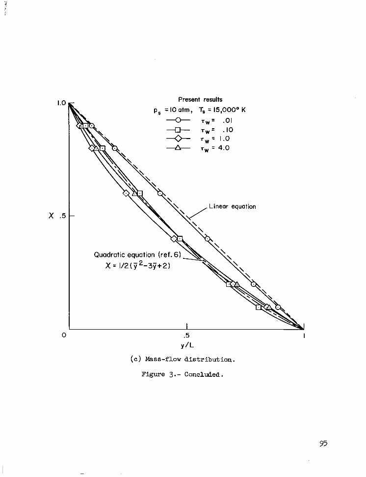
I .o
x .5
0 .5 Y/L
( c ) Mass-flow dis t r ibu t ion .
Present results
p, = IO atm, T, = 15,000° K
T w = .01 -E+ T W = -10 + r w = 1.0 & T~ = 4.0
I
Figure 3 . - Concluded.
95

. I -
-- Plane shock flow ( y = 0) Stagnation flow (y= I )
I I .--=;d ... - - ~ ~ . . ~ -~~
0 I 2 t W
(a) p, = 1 a t m , Ts = 15,000° K
a .-
.2
r
. I
0 T W
(b) p, = 10 a t m , T, = 15,00O0 K
Figure 4.- Radiative heat fluxes a t t he shock and a t the wall.

.4
x
.2
0
.4
x
.2
0
(a) V, 30 h / s e c , H 67 lan.
- I I I I .2 .4 .6 .8
T W
(b) V, 30 km/sec, H = 49 km.
Figure 5.- Radiative heat a t the shock and a t the w a l l ( 7 = 1).
97

I .o-
.6 -
.4 -
0 Howe and Viegas 0 Wilson and Hoshizaki
ps = I atm
ps = IO atm A Howe and Viegas
ps = I atm Ts = 15,000° K
nl I I 70-2 Io-' I IO'
xo =(2 q0)/1/2 Pa, vm3
( c ) Effect of nonadiabatic flow on radiative heat at the w a l l .
Figure 4.- Concluded.

I.0-
.8 - "= latm }V'= 30km/sec
A ps= IOatm
.4 - ps = I atm
vref = 15 km/sec TS = 15,000" K
.2 -
01 I 10-2 10-1 I IO1 IO2
(c ) Effect of nonadiabatic flow on radiative heat a t the w a l l .
Figure 5.- Concluded.

I lIIll11111l11111ll 1ll1l1llll1l 1ll111l1l1l1l I1 I I1
I .o
.0
.6
- h
.4
.2
0
I .o
.8
.6
- h
.4
.2
0
(a) p, = 1 a t m , T, = 1.5,000° K
.2 .4 .6 .0 I .o
Shock
- r Wal I
(b) p, = IU a t m , xs = 13,uuu K
Figure 6 .- Enthalpy d is t r ibu t ion a s a function of op t ica l thickness ( y = 1).
100

I .o
.a
T
.6
.4
.2
0
dr a 7
-. 2
-.4
.04
.02
r
0
- .02
- \ \ b \ \ \ \
\ \
ps IO atm, Ts 15,000" K 0 Y = .59 (rW = ,051 0 u 1.87 (rW = 1.0)
T \ aria i
r \
\ 4
'4
I I I I I -.04
i
Figure 7.- Distributions of temperature, radiat ive heat f lux, and heat-flux der ivat ive in shock l ayer .
101

1.0 -
.8 -
T, = 15,00O0 K
.6 -
.4 -
\
.2 -
01 I IO-^ 10-2 10-1 I IO'
I I I
f W
Figure 8.- Effect of absorption in shock layer on gas temperature a t the w a l l .

1.0 - p, = IO atm ps = latm
0 Howe and Viegas
--
T, = 15,000° K
\ \
\ \
\ \
YTS = 1510000
\ \ \
L - Lo
\
\ \ ‘\
T, = 35,OOOO K
.6 -
‘I. --
.4 L I
I I O
1 I 03
I I 04
Figure 9.- The effect of nonadiabatic flow on shock-standoff distance.
P 0 w

P 0 i=
I .o ps= IOatm Ts = I 5,000' K, Tw N 5,000' K cs = r s = rw =O
.€I -
.6 -
I
r w b 4wb =
.4 -
.2 -
0' I I
IO-^ 10-2 Io-' I IO' I Lb
TWb = 7 xOrWO KO B (a) Injection layer .
Figure 10.- Effect of absorption i n inject ion and ablat ion layer on radiat ive heat flux t o the w a l l .

Shock Interface Wall
.8 -
.6 -
.4 -
.2 -
/ I I
I I rwb
\ \
V, 12 km/sec ps N IO atm
5 5 X 1 0 7 J l k g
0 ’ I I I I 10-2 10-1 I IO’
PbKb
I-‘ 0 ul
ps “s
(b) Ablation layer.
Figure 10.- Concluded.
R

2.2-
2
#wp =
I
I
I
I - r w P
r w o I
2.0-
I .8- - r w P
r w o I .6-
I .4 -
Body radius, R, meter
(a) P, = 1 a t m , T, = 15,000° K (V, = 15 km/sec, H 58 km) . 2.2 -
/ Shock Wal I 2.0 -
1.8 -
1.6-
Body radius, R, meter
(b) ps = 10 a t m , T, = kO,OOOo K (V, 30 b/sec , H = 49 km) . Figure ll.- Effect of preheating on radiative heat t o the wall.
106

1.0-
.8 -
.6 -
q C - qco
.4 -
.2 -
h
Ts = 15,000° K
0 0 Howe and Viegas
ps = I O atm Y
ps = I atm
Figure 12.- The effect of radiative heat on convective heat to the wall.
P 0 -4

I20
100
80
E Y - I 6 60
a
U ¶ c c _- -
40
20
0
c
ps=10-3 atm
/ IO ,
5 IO 15 20 25 30 Velocity, Va, km/sec
(a) Pressure.
IO-^
10-6
1 0 ' ~
- IO-^
- 10-3
- 10'2
- IO"
- I
Figure 13.- Thermodynamic properties behind shock f o r equilibrium a i r .

0 5 10 15 20 25 30 Velocity, V,, km/sec
(b) Temperature.
Figure 13.- Continued.

I-' I20 I-' 0
too
80
E x
4c
2(
0 5 IO 15 20 25 30 Ve I oc i t y , V, , km /sec
( c ) Density r a t i o across shock.
Figure 13.- Concluded.

- 120 -
100 -
80
E Y
i 6 60
z '0 3 t c _-
40
20
0 IO 15 Velocity, V,, km/sec
(a) Radiative intensity.
20 25
Figure 14. - Radiative properties behind shock for equilibrium air.
30

RTo = 82.73 J/gm
2
-4
in
-6 - I I I I I I I I I I 20 30 40 50 60 70 80 90 100 0 IO
2/hlRTo (b ) Planck mean absorption coefficient.
Figure 14. - Concluded.

“The aeronautical and space activities of the United States shall be conducted so as to contribute . . . to the expansion of human Rnowl- edge of phenomena in the atmosphere and space. The Administration shall provide for the widest practicable and appropriate dissemination of information concerning its activitieJ and the results tbereof.”
-NATIONAL AERONAUTICS AND SPACE ACT OF 1958
NASA SCIENTIFIC AND TECHNICAL PUBLICATIONS
TECHNICAL REPORTS: Scientific and technical information considered important, complete, and a lasting contribution to existing knowldge.
TECHNICAL NOTES: Information less broad in scope but nevertheless of importance as a contribution to existing knowledge.
TECHNICAL MEMORANDUMS: Information receiving limited distribu- tion because of preliminary data, security classification, or other reasons.
CONTRACTOR REPORTS: Scientific and technical information generated under a NASA contract or grant and considered an important contribution to existing knowledge.
TECHNICAL TRANSLATIONS: Information published in a foreign language considered to merit NASA distribution in English.
SPECIAL PUBLICATIONS: Information derived from or of value to NASA activities. Publications include conference proceedings, monographs, data compilations, handbooks, sourcebooks, and special bibliographies.
TECHNOLOGY UTILIZATION PUBLICATIONS: Information on tech- nology used by NASA that may be of particular interest in commercial and other non-aerospace applications. Publications indude Tech Briefs, Technology Utilization Reports and Notes, and Technology Surveys.
Details on the availability of these publications may be obtained from:
SCIENTIFIC AND TECHNICAL INFORMATION DIVISION
NATIONAL AERONAUTICS AND SPACE ADMINISTRATION
Washington, D.C. PO546