ANALYSIS OF PRE-CAST WAFFLE SLABS USING YIELD LINE AND...
219
1 ANALYSIS OF PRE-CAST WAFFLE SLABS USING YIELD LINE AND RANKINE GRASHOFF THEORIES BY Joseph Olawale AKINYELE S.I 74757 B. Sc. (Hons), M. Sc. Civil Engineering (Ibadan) A Thesis in the Department of Civil Engineering, Submitted to the Faculty of Technology in partial fulfillment of the requirement for the Award of DEGREE OF DOCTOR OF PHILOSOPHY of the UNIVERSITY OF IBADAN, NIGERIA September, 2012.
Transcript of ANALYSIS OF PRE-CAST WAFFLE SLABS USING YIELD LINE AND...

1
ANALYSIS OF PRE-CAST WAFFLE SLABS USING YIELD LINE
AND RANKINE GRASHOFF THEORIES
BY
Joseph Olawale AKINYELE
S.I 74757
B. Sc. (Hons), M. Sc. Civil Engineering (Ibadan)
A Thesis in the Department of Civil Engineering,
Submitted to the Faculty of Technology
in partial fulfillment of the requirement for the Award of
DEGREE OF DOCTOR OF PHILOSOPHY
of the
UNIVERSITY OF IBADAN, NIGERIA
September, 2012.

2
ABSTRACT
Failure in pre-cast waffle slabs can be attributed to factors like analytical error, poor
handling during transportation and placement which factors often lead to partial/total failure of
slabs. The conventional method of analysing waffle slabs focuses on the ribs, while the slab
portions at the top are avoided. This has led to under reinforcement and subsequent failure of the
slab portions that are usually in direct contact with loads. In this study, a method that
incorporates both the slab and rib portions in the analysis of pre-cast waffle slabs was therefore
developed.
Yield Line and Rankine Grashoff Theories (YLRGT) were combined for the analysis of
pre-cast waffle slab. Six physical models of waffle slab were developed, each having five
replicates, with the following dimensions: W1 (1353 x 430 x 58 mm), W2 (900 x 300 x 50 mm),
W3 (1085 x 430 x 58 mm), W4 (407 x 364 x 50 mm), W5 (1312 x 300 x 58 mm) and W6 (860 x
360 x 50mm). Solid slabs of the same size and number designated S1, S2, S3, S4, S5 and S6
served as control. These models were validated using the slabs by testing for failure loads,
deflections and crack width. Each slab was subjected to incremental load of 1.0 kN until failure
occurred. Maximum bending moments were obtained for slab and rib portions using YLRGT, a
finite element based method called ETABS was also used to analyse the slabs and results
obtained were subjected to statistical analysis using ANOVA at p= 0.05.
The YLRGT analysis of the various physical models (slab portion, transverse and
longitudinal ribs) yielded the following bending moments: W1 (5526.0, 34.5, 918.3) Nm, W2
(1122.0, 279.2, 36.5) Nm, W3 (2880.0, 27.2, 619.9) Nm, W4 (590.0, 171.9, 160.9) Nm, W5
(947.0, 37.0, 4.4) Nm and W6 (1276.0, 90.4, 36.2) Nm respectively. The ETABS combined both
slab and ribs giving W1 (4729.0) Nm, W2 (581.0) Nm, W3 (3338.0) Nm, W4 (733.0) Nm, W5
(851.0) Nm and W6 (686.0) Nm. Deflections at failure for waffle slab were smaller compared to
solid slabs: (W1 = 1.19 and S1 =3.56) mm, (W2 = 3.64 and S2 =9.28) mm, (W3 = 3.90 and S3
=7.44) mm, (W5 = 8.17 and S5 =12.18) mm, (W6 = 3.29 and S6 =3.89) mm with the exception
of W4 (6.60 mm) and S4 (6.44mm), where deflection of waffle slab was higher than that of solid
slab. Mean deflection of S1 was significantly higher than W1, while S2 was significantly higher

3
than W2. Average crack width for waffle (0.48 mm) and solid slabs (0.99 mm) were significantly
different. High crack width in solid slab indicated lower shear strength.
The Yield Line and Rankine Grashoff Theories have facilitated the accurate analysis of
pre-cast waffle slabs by separating the slab and rib portions.
Keywords: Yield line theory, Rankine Grashoff theory, Waffle slabs, Crack width.
Word Count: 464
DEDICATION
Unto God, who was, who is and who is to come. To Him is all the Glory For Ever.

4
ACKNOWLEDGEMENTS
To God Almighty, the invincible, Immortal and the only wise God, author and
finisher of my faith, the maker of heaven and earth, for His grace, faithfulness, His
mercy, wisdom and the strength He gave me to finish this work, I am forever grateful for
this privilege.
I wish to express my profound gratitude to my supervisor, Dr. G.A. Alade, for his
fatherly counsel, guidance, useful suggestions and encouragement throughout the
duration of the study. You are a father and a good mentor indeed. May the Lord God
bless and keep you. Also to my Co-supervisor, Dr. B.I.O. Dahunsi, who took his time to
provide useful suggestions for the successful completion of this work.
My gratitude goes to the Heads of Department and members of staff of the
Department of Civil Engineering, University of Ibadan and Federal University of
Agriculture, Abeokuta for their moral supports and encouragements during the course of
this research work. I will not fail to mention the following people, Prof. O.A Agbede,
Prof. A.O. Coker, Dr. F.A.Olutoge, Dr.W.K. Kupolati, Dr.G.M. Ayinuola, Engr. W.O.
Ajagbe and Dr. (Mrs) F.O. Akintayo all of the University of Ibadan. Also to all my
colleagues at Federal University of Agriculture, Abeokuta (FUNAAB) and Mr. Dipo
Oyewole, also my professional colleagues, Dr H. Mohamed, Engr. Olaoye and Engr.
Labiran. I appreciate you all.
To the staff of the Mechanical Engineering Laboratory of The Polytechnic Ibadan,
and Civil Engineering Laboratories of University of Ibadan and FUNAAB, where all the
laboratory works were carried out, thank you all for the support and cooperation.
I will not forget to mention my mentor and counselor, Prof. and Dr. (Mrs.) J.O.
Akinyemi, you are blessed. My friends, Dr. (Mrs) Olutobi Oluwole, Debo and Tosin
Adesina, Seyi and Yinka Isola, Dr. and Dr. (Mrs.) Adebayo, Dr. Olawoyin and Aunty
Tolu and other friends that can not be mention, thank you all.
To my late father, Mr Philip Akinyele “BABA SOJA”, I wish you were alive to
see this day, but the Lord God has a better plan. And to my mother Mrs Modupeola
Akinyele, thank you for being there for me. My parent in-law, Mr and Mrs. Emmanuel
Onibokun, may the Lord preserve you and keep you so that you can eat the fruit of your
labour. To all my siblings, Aunty Yemisi (who passed on in the course of this
programme), „Egbon‟ Lekan and his family, Aunty Bose, Olakunle and his children of

5
blessed memory, Bukola Oke- Akinyele, Yinka and Seun Raji, Mr and Mrs Sola Jebutu
and Family, Dr. S.O.S. Akinyemi and family, Dr. and Dr. (Mrs.) Aduramigba-Modupe,
Dr. and Dr. (Mrs.) Sola Ojurongbe, Mr and Mrs. Sam. Olanipekun, Tunde and Debola
Folorunso, and Tolu „sholu‟, my uncles and aunties, I wish you all well.
To my Pastor and Spiritual guide, Rev. Abiodun Aladekomo and Mummy
Aladekomo, all the members of the New Covenant Church Basorun, Ibadan, Rev. Odunjo
& family, Rev. Adeniji and family, Pastor and Mrs Israel Adeyemi and family, Pastor
Dele Adeyemi and family, Rev. Akin Feyisetan and family, and many others that deserve
my appreciation.
To my beautiful daughters and little angels, Oreoluwa Oluwafeyijimi and
Ooreoluwa Olaoluwasubomi, and my little boy Adeoluwa Olorunjuwon Akinwumi, I just
love you all, you make my life worth it and thanks for all the disturbances, questions and
the „hiding‟ games, I really enjoy it all. To my Soul mate and confidant, Adejoke
Olukemi Akinyele, you are always there for me; I really love you from the depth of my
heart. Thank you for making my life great and better.

6
CERTIFICATION
I certify that this work was carried out by JOSEPH OLAWALE AKINYELE
in the Department of Civil Engineering, University of Ibadan, Nigeria.
------------------------------------------------------------
Supervisor
G. A. ALADE
B.Sc (Zaria), Ph.D (Leeds), FNSE
Department of Civil Engineering,
University of Ibadan, Nigeria.
------------------------------------------------------------
Co-Supervisor
B.I.O. Dahunsi
B.Sc (Ife), M.Sc, Ph.D (Ibadan), MNSE
Department of Civil Engineering,
University of Ibadan, Nigeria.

7
TABLE OF CONTENTS
page
TITLE ………………………………………………………………………….………...i
ABSTRACTS……………………………………………………………………………..ii
DEDICATION………………………………………………………………………. ….iv
ACKNOWLEDGEMENTS………………………………………………………………v
CERTIFICATION ……………………………………………………….…………….. vii
LIST OF TABLES ……………………………………………………….…………..… xi
LIST OF FIGURES ……………………………………………………….………….. xii
LIST OF PLATES ………………………………………………………….………… xiii
LIST OF SYMBOLS ………………………………………………………………….. xiv
CHAPTER ONE: INTRODUCTION 1
1.1 Background ………………………………………………….………...……….1
1.2 Aim and Objectives …………………………………………………………….5
1.3 Justification ………………………………………………………………...…..6
1.4 Scope of the study …………………………………………………………...…7
1.5 Problems Encountered ………………………………………………………….7
CHAPTER TWO: LITERATURE REVIEW 8
2.1 History of Reinforced Concrete…………………..…………………...………..8
2.2 Analysis of Waffle Slabs ……………………………………………....……….9
2.3 Analytical Procedures ………………………………………………….……..10
2.3.1 Finite element method ………………………………………………….……..10
2.3.2 Grillage analysis ……………………………………………………….……...12
2.3.3 The plate theory ………………………………………………………..……...15
2.4 Computer Programs ……………………………………………………..…..…18
2.4.1 Fortran 77…………………………………………………………………..…...18
2.4.2 SAP 2000 …………………………………………………………………..…..19
2.4.3 Adapt Floor Program ………………………………………………..………....20
2.4.4 SAFIR Program……………………………………………………..……..……21
2.4.5 RCC Program………………………………………………………..……...……21
2.4.6 ETABS……………………………………………………………..………...…..21

8
2.5 The Yield Line Theory ………..……….………………………………………..22
2.5.1 Energy dissipation ………………………..…………………………………….22
2.5.2 The contribution from the concrete ……………………………………..……….27
2.5.3 Contribution from reinforcement ………………...……………………………...30
2.6 Isotropic and Orthotropic Slabs…………………………………………………..33
2.7 Definition of upper and lower bound theorems..…………………………………33
2.8 Difference in load distribution in waffle and solid slabs ………………………...34
2.8.1 Load path designation in waffle slabs ………………………………………....35
2.8.2 Load path designation in solid slabs …………………………………………...36
CHAPTER THREE: METHODOLOGY 37
3.1 Preamble…………..…………………………………………………………....37
3.2 Mathematical Formulation for the Experimental Studies ……………………...37
3.2.1 Analysis of Slabs adopting Yield Line Theory…………………………………37
3.2.2 Analysis of ribs adopting the Rankine Grashoff Formulae…………….………51
3.3 Computer Program for The Analysis and Design of Waffle slabs…….…..…...52
3.4 Materials ……………………………………………………………………… 52
3.4.1 Concrete ……………………………………………………………………….52
3.4.2 Reinforcement ………………………………………………………………….52
3.5 Description of Specimens ……………………………………………………...54
3.5.1 Modelling of Specimens ……………………………………………………….58
3.6 Casting of Specimens ………………………………………………………….60
3.7 Instrumentation…………………………………………………………………61
3.8 Experimental Set-up and Procedure …………………………………………....61
3.9 The analysis of the Prototype……………………………………………..….…67
3.10 Analysis of Data…………………………………………………………..…….67
CHAPTER FOUR: RESULTS AND DISCUSSION 68
4.1 Structural Response of Specimens to Loads.………………………...…….…….68
4.1.1 General observation of structural response of specimens to load ……………..71

9
4.2 Bending Moments of Specimens…..……………………………………….....…81
4.2.1 Comparison of bending moments of waffle slabs and solid slabs……………….85
4.2.2 Effects of slab sizes and ribs on the bending moments of waffle slabs……….....86
4.2.3 Effects of slab size on the bending moments of solid slabs………….……….…88
4.3 Assessment of the Rankine Grashoff and BS8110 Slab Coefficients Factors……….90
4.4 Comparison of YLRGT and ETABS……………………………………………...…93
4.4.1 Outcome of W1 and W3………………………………………………………...…93
4.4.2 Results of W2 and W4…………………………………………………………..…93
4.4.3 Comparison of W5 and
W6…………………………………………………...……95
4.4.4 General observations on YLRGT and ETABS….....................................................95
4.5 Deflections in Specimens……………………..……………………………..…..…96
4.6 Mean Deflection in Waffle slabs and Solid
slabs…………………………..….......105
4.7 Correlation between the Deflection in slabs of Similar Support
Condition………...109
4.8 Flexural Cracking …………………………………………………………..………110
4.8.1 Comparison of mean crack width between Waffle slab and Solid slab…….…….112
CHAPTER FIVE: CONCLUSION AND RECOMMENDATIONS
114
5.1 Conclusions…..……………………………………………………………….…….11
4
5.2 Contribution to Knowledge ………………………………………..………….…..116
5.3 Recommendations ………………………………………………..……………….117
REFERENCES ………………………………………………………………………...118
APPENDICES..........................................................................................................…...125

10
LIST OF TABLES
Page
Table 3.1 Template for the computer analysis and design of simply supported waffle
slabs adopting the yield line theory( supported on all four
sides)…………..43
Table 3.2 Template for the computer analysis and design of simply supported waffle
slabs adopting the yield line theory ( supported on 3
sides)………….……….46
Table 3.3 Template for computer analysis and design of waffle slabs, supported on two
short sides, adopting the yield line
theory…………….……………..……….49
Table 3.4: Panel properties for waffle slab
prototypes.………………….…………........55
Table 3.5: Panel properties of the waffle models
…………………………….……...….56
Table 3.6: Panel properties of the solid slab models
…………………………….…..….57
Table 4.1 Deflection of Slabs under load
………………...…………………...…...…...69
Table 4.2 Crack properties of slabs under
load……………………..…………….…....70
Table 4.3 Comparison of theoretical and experimental bending moments
(Waffle
slab)………………………….……………………………………..82
Table 4.4 Comparison of theoretical and experimental bending moments
(Solid
slab)………...…………………………………………………….…..83
Table 4.5 Summary results for BS 8110 and Rankine theory ……………….…….....91
Table 4.6 Comparison of the bending moments of ETABS and
YLRGT………..…...94

11
Table 4.7 Least significant difference table for S1 and W1
………………….…...….106
Table 4.8 Least significant difference table for S2 and
W2…….………………….…107
Table 4.9 Crack width at failure and service
……………………………………….…111
Table 4.10 Least significant difference table for crack width of waffle and
Solid Slabs
……………..……………………………………………………113
LIST OF FIGURES
Page
Figure 1.1 Detailed View of a waffle slab Floor…………………………………..3
Figure 2.1: Plate Structure…………………………………………………………16
Figure 2.2: Yield line from the angle of a slab ……………………………………24
Figure 2.3: Displacement for two slab parts ……………………………….….…25
Figure 2.4: Geometry relation between rotations …………………………….…...26
Figure 2.5: Reinforcement arrangement ………………………………………….32
Figure 3.1: A simply supported one-way slab ……………………………………38
Figure 3.2: Yield line on two- way simple supported slab ……………………….40
Figure 3.3: Reinforcement arrangement for slab and ribs in waffle slabs…………..53
Figure 4.1 Variation in deflection of W1 and S1…………………………………..97
Figure 4.2 Variation in deflection of W2 and S2………………………………….98
Figure 4.3 Variation in deflection of W3 and S3………………………………….99
Figure 4.4 Variation in deflection of W4and S4…………………………………..100
Figure 4.5 Variation in deflection of W5 and S5…………………………………..101
Figure 4.6 Variation in deflection of W6 and S6………………………………….102

12
LIST OF PLATES
Page
Plate 1: Stacked slabs …………….…………………………………………………….63
Plate 2: Some samples of waffle slabs……………………………………………….…64
Plate 3: The universal testing machine with welded steel supports for slabs…………..65
Plate 4: Test arrangement for a slab sample…………………………………………….66
Plate 5: Crack pattern for waffle slabs W1 Supported on 2 short sides ……………..….72
Plate 6: Crack pattern for waffle slab W2 Supported on all 4 sides……..……….….…..73
Plate 7: Crack pattern for waffle slab W4 Supported on all 4 sides …..……………...…74
Plate 8: Crack pattern for solid slab S2 Supported on all 4 sides……………………......75
Plate 9: Crack pattern for solid slab S4 Supported on all 4 sides……………………......76
Plate 10: Crack pattern for waffle slab W5 Supported on 1 long side and 2 short sides...77
Plate 11: Crack pattern for solid slab S5 Supported on 1 long side and 2 short sides…...78
Plate 12: Crack pattern for solid slab S6 Supported on 1 long side and 2 short sides…...79
Plate 13: Crack pattern of a failed waffle slab bottom…………………………………...80
13
LIST OF SYMBOLS
The most commonly used symbols are listed below. Exceptions from the list may appear,
but this will then be noted in the text in connection with the actual symbol.
h = Height of a cross-section
A = Area of a cross-section
Ac = Area of a concrete cross-section
As = Area of reinforcement close to the bottom face
As’ = Area of reinforcement close to the top face
Asc = Area of reinforcement in compression
hc = Distance from the bottom face to the centre of the bottom reinforcement
hc’ = Distance from the top face to the centre of the top reinforcement
yo = Compression depth
L = Length of an element
Lx,Ly = Length of a slab in the x and y direction, respectively
e = Eccentricity
u = Deflection
um = Deflection in the mid section
x, y, z= Cartesian coordinates
fc = Compressive strength of concrete
fy = Yield strength of reinforcement
Reinforcement ratio
Degree of Reinforcement
x, y = Degree of Reinforcement in the x and y direction, respectively
p = Line load, uniform load per unit length
q = Surface load, uniform load per area unit
mp = yield moment in pure bending
mpx, mpy = yield moment in pure bending in the x and y direction, respectively
mf = yield moment for a given axial load
mfx, mfy = yield moment for a given axial load in the x and y direction, respectively
n = Axial load per unit length
nx, ny = Axial load per unit length in the x and y direction, respectively
Wi, We = internal and external work, respectively
Wc, Ws = concrete and reinforcement contribution to the dissipation, respectively
M = mass
T = time
N = load acting within a particular region (kN)
ζ = stress
= vertical displacement of the load N on each region expressed as a fraction of
Unity (m)

14
δ = unit weight
m = ultimate design moment of resistant for the slab (kNm)
θ = rotation of the region about its axis of rotation (m/m)
ar = reduced short span dimension
br = reduced long span dimension
k = a constant = 1
v = a variable = 0 < 0.5
i = the fixity ratio at supports, e.g i1, i2.
If : i1 = i2 = 1, that support is a continuous support
And i1 = i2 = 0 that support is a simple support.
a1 and b1 = are the spacing of the ribs on the short and long span respectively.
q = total load per unit area
q1 and q2 = the load shared on the short and long span respectively
a = Shorter dimension of grid
b = Longer dimension of grid
Mx and My = moments on the short and long span respectively
Qx and Qy = the shear forces on the short and long span respectively.
Lp = Diameter of bars in the prototype
Lm = Diameter of bars in the model
δp = Characteristic strength of steel used in the prototype
δm = Characteristic strength of steel used in the model

15
LIST OF APPENDICES
Page
Appendix 1: Theoretical result of waffle slab W1……………………………………126
Appendix 2: Theoretical result of waffle slab W2……………………………………128
Appendix 3: Theoretical result of waffle slab W3…………………………………....129
Appendix 4: Theoretical result of waffle slab W4…………………………………....129
Appendix 5: Theoretical result of waffle slab W5…………………………………....130
Appendix 6: Theoretical result of waffle slab W6…………………………………....131
Appendix 7: Theoretical result of solid slab S1………………………………………132
Appendix 8: Theoretical result of solid slab S2……………………………………....133
Appendix 9: Theoretical result of solid slab S3………………………………………134
Appendix 10: Theoretical result of solid slab S4…………………………………..…135
Appendix 11: Theoretical result of solid slab S5………………………………..……136
Appendix 12: Theoretical result of solid slab S6…………………………….……….137
Appendix 13: Experimental result of waffle slab W1…………………….………….138
Appendix 14: Experimental result of waffle slab W2………………………………..139
Appendix 15: Experimental result of waffle slab W3………………………………..140
Appendix 16: Experimental result of waffle slab W4…………………………….….141
Appendix 17: Experimental result of waffle slab W5………………………..………142
Appendix 18: Experimental result of waffle slab W6…………………….………….143
Appendix 19: Experimental result of solid slab S1…………………….…………….144
Appendix 20: Experimental result of solid slab S2………………….……………….145
Appendix 21: Experimental result of solid slab S3......................................................146
Appendix 22: Experimental result of solid slab S4…………….…………………….147
Appendix 23: Experimental result of solid slab S5………….………..……………..148

16
Appendix 24: Experimental result of solid slab S6………..…………….………...…149
Appendix 25: Result of waffle slab using the example in Mosley et al………....…..150
Appendix 26: Waffle slab results of Mosley et all. Adopting BS8110 Coefficients…..152
Appendix 27: Result of waffle W1 Theoretical (ETABS)…………………………….154
Appendix 28: Result of waffle W2 Theoretical (ETABS)……………………...……...157
Appendix 29: Result of waffle W3 Theoretical (ETABS)……………………...……...160
Appendix 30: Result of waffle W4 Theoretical (ETABS)……………………………..163
Appendix 31: Result of waffle W5 Theoretical (ETABS)……………………………..166
Appendix 32: Result of waffle W6 Theoretical (ETABS)……………………………..169
Appendix 33: Result of waffle W1 Experimental (ETABS)…………………………..172
Appendix 34: Result of waffle W2 Experimental (ETABS)…………………………..175
Appendix 35: Result of waffle W3 Experimental (ETABS)…………………...……...178
Appendix 36: Result of waffle W4 Experimental (ETABS)………………...………..181
Appendix 37: Result of waffle W5 Experimental (ETABS)…………………………..184
Appendix 38: Result of waffle W6 Experimental (ETABS)…………………………..187
Appendix 39: Test results for panel W1………………….………………….…….…..190
Appendix 40: Test results for panel W2……………………………………..……..….190
Appendix 41: Test results for panel W3……………………………………..………...191
Appendix 42: Test results for panel W4……………………………………………….191
Appendix 43: Test results for panel W5………………………………………………..192
Appendix 44: Test results for panel W6………………………………………………..192
Appendix 45: Test results for panel S1…………………………………………………193
Appendix 46: Test results for panel S2……………………………………………..….193
Appendix 47: Test results for panel S3……………………………………………..….194
Appendix 48: Test results for panel S4……………………………………………..….194
Appendix 49: Test results for panel S5……………………………………………..….195
Appendix 50: Test results for panel S6……………………………………………..….195
Appendix 51: Analysis of variance table for W1 and S1……………………….…..….196
Appendix 52: Analysis of variance table for W2 and S2……………………….…..….196
Appendix 53: Analysis of variance table for W3 and S3……………………….…..….196
Appendix 54: Analysis of variance table for W4 and S4……………………………….197
Appendix 55: Analysis of variance table for W5 and S5…………………………….....197

17
Appendix 56: Analysis of variance table for W6 and S6…………………………….....197
Appendix 57: Correlation analysis for W1 and W3……………………………….……198
Appendix 58: Correlation analysis for W2 and W4……………………………………198
Appendix 59: Correlation analysis for W5 and W6……………………………………198
Appendix 60: Correlation analysis for S1 and S3………………………………………199
Appendix 61: Correlation analysis for S2 and S4…………………………………...….199
Appendix 62: Correlation analysis for S5 and S6……………………………………....199
Appendix 63: Estimation of flexural crack width at service for Slab S1….………..…..200
Appendix 64: Analysis of variance table of crack width for Waffle and Solid slabs…..201

18
CHAPTER ONE
INTRODUCTION
1.1 Background
Reinforced concrete slabs are one of the most common structural engineering elements.
They are used as floors and roofs, to carry vertical loads in structures such as buildings
and bridges. A slab is part of a reinforced concrete structure which is often subjected to
bending (tensile or compressive) but in rare cases, subjected to shear, such as a bridge
deck. In most cases, slabs are horizontal members but they can be used as vertical
members, such as walls, to infill panels, side to drains and sewers appurtenances
(Oyenuga, 2001).
The various types of slabs include:
(a) Solid slab,
(b) Ribbed slab,
(c) Flat slab, and
(d) Waffle slab.
The type to be preferred may depend on:
(i) span of the slab,
(ii) use of the space which may determine the span,
(iii) load to be carried, and
(iv) architectural aesthetics that is required.
Most of the researches carried out on yield line theory have basically been on
solid slabs with little or no research on waffle slabs. According to Mosalam and Naito
(2002), a limited number of experimental studies exist in the literature concerning
waffle slabs.
Waffle slab has its genesis in a rather thick solid-slab floor from which the bottom
layer concrete in tension is partially replaced by their ribs along orthogonal directions.
19
The ribs are reinforced with steel to resist flexural tensile stresses. The dimensions and
spacing of ribs are decided in a manner so as to achieve better load distribution without
requiring the shear reinforcement (Prasad et al. 2005).
Waffle slabs are generally employed in large span slabs, as spans become larger
still, the required slab thickness for the flat plate and flat slab increases to the point
where the slab may be unable to carry its own weight. A solution to this is to provide
thickness so that reinforcement can be placed in a member at greater depth, but remove
concrete from regions of the slab not required for strength (Konda, 2003). It is an
extension of the ribbed floor slab in which the slab is ribbed in two directions. Hence,
an inverted pot-like hollow is formed which serves as the ceiling for the floor below,
(Figure 1.1.). Waffle slabs are all concrete. The inverted pot-like shape is formed
through the use of a special mould. When compared with the conventional solid flat
slab construction, waffle slabs allow a considerable reduction in dead load; can support
heavy loads over a long span (Daniel and Onur, 2005). It is commonly used in parking
garages of tall buildings with ramps and also in industrial facilities and warehouses
(Buildings, 2005) and meet fire proofing requirements (Sadusky, 2004; Kenichi and Ai,
2005). Also, it has the advantage of medium to long span, light weight, economical in
material usage and profiles may be expressed architecturally or used for heat transfer
(The concrete centre, 2006). This slab is usually employed for architectural and
structural reasons for large rooms such as auditoria, vestibules, theatre halls, show
rooms of shops where column-free-space is often the main requirement (Krishna Raju,
1988).

20
Figure 1.1: Detailed view of a waffle slab floor
According to Howard and Hansen (2002), waffle floors are used extensively in
semiconductor factories as they provide high impedance mounts for manufacturing
equipment that is extremely vibration sensitive. Also it has been used for cooling
21
towers, storage tanks, communication shelters, barriers and retaining walls, artificial
reefs, building walls, hybrid columns and beams (Waffle-Crete international, 2009).
Deflection or failure in slab can occur due to some factors like overloading,
under-reinforcement and poor span-depth ratio. Under overloading, failure of a slab
will occur when the reinforcement yields first in a region of high moments. According
to Wang et al (2003), when concrete is under triaxial compressive loading, both its
strength and ductility will have a significant increase as a result of resistance to the
compressive force by the concrete materials (molecules). Initially, at service load, the
response of a slab is elastic with maximum steel stress and deflection occurring at the
centre of the slab. At this stage, it is possible that some hairline cracking will occur on
the suffix where the flexural tensile capacity of the concrete has been exceeded at mid
span. Increasing the load hastens the formation of these hairline cracks. Further
increment of the load will increase the size of the cracks and induce yield of the
reinforcement, initiating the formation of large cracks emanating from the point of
maximum deflection (Kennedy and Goodchild, 2004). This portion acts like a plastic
hinge. On increasing the load further, the hinging region rotates plastically and the
moments due to additional loads are redistributed to adjacent sections, the concrete
section at the position of a yield line is incapable of carrying any further load, causing
them to collapse (Thompson and Haywood, 1986; Macgregor, 1997).
Yield line theory investigates failure mechanism at the ultimate limit state. It does
not deal with serviceability issues such as deflection per se. Nonetheless, deflection
can be dealt with by simple formulae based on yield line moment (Kennedy and
Goodchild, 2004). The basic assumption of the yield line theory is that a reinforced
concrete slab, similar to a continuous beam or frame of a perfectly plastic material will

22
develop yield line hinges under overload, but will not collapse until a mechanism is
formed (Dunham,1964). The theory also permits the prediction of the ultimate load of a
slab system by postulating a collapse mechanism which is compatible with the
boundary conditions (Buyukozturk 2004). Yield-line analysis is seen as a useful
technique to determine the collapse load of slabs (Johansen, 1963). The band in which
yielding has occurred are referred to as yield lines which divide the slab into a series of
elastic plates.
The use of yield line analysis requires knowledge of the plastic flexural capacity
of the slab, and the results serve as an upper bound on the ultimate load of the system.
The results of yield line analysis for a given slab are either correct or too high and are
highly dependent on proper selection of a failure mechanism (Park and Gamble, 2000).
The Rankine Grashoff theory of equating deflections at the junctions of ribs is
used for the analysis of ribbed or grid floors. The method considers the load in a slab
and distribute to all the ribs along both the longitudinal and transverse directions.
1.2 Aim and Objectives
The aim of this work was to develop a method of analysing precast waffle slabs of
different sizes, under various support conditions.
The objectives of this study are to:
i. Apply Yield Line and Rankine Grashoff Theories (YLRGT) to waffle slabs subjected
to axial loading.
ii. Determine the structural characteristics of waffle slabs.
iii. Develop a computer based method called YLRGT for the analysis and design of
waffle slabs.
iv. Validation of the program developed.

23
1.3 Justification
Structural failure in building was attributed to both technical and human errors by
Carper (1998). He listed some causes of failure in civil engineering structures to
include: programming deficiency, site selection and site development errors, design
errors, construction errors, material deficiencies, and operational errors. Of all the
causes mentioned, the programming and design errors were the main problems that this
study has tried to look at and proffer appropriate solutions.
Yield line design leads to slabs that are quick and easy to handle. The resulting
slabs are light and have very low amounts of reinforcement in very regular
arrangements. Above all, yield line design generates economic concrete slabs, because
it considers failures at the ultimate limit state (Kennedy and Goodchild, 2004). Since
waffle slab is considered to be economical due to its reduced concrete volume, if
compared with solid slabs, Yield line theory will be applied in order to investigate its
structural response to loading.
In most of the works that have been carried out on waffle slabs, it was only the
ribs that were analysed with the provision of adequate reinforcements, but the slab
portion has often being left unanalysed. Most designs simply provided wire meshes for
the slab portion. Mosley et al (1999) simply adopted 12% of the cross section area of
the slab portion as wire mesh reinforcements. However, this method has been found to
be adequate for slabs that are cast in-situ only, since they are not subjected to the same
eccentric forces generated as a result of lifting and transportation of precast waffle slab
from the manufacturing plant to the site. In some factories where precast waffle slabs
are manufactured using wire mesh in the slab portions, the precast slabs were subjected

24
to both hogging and sagging moments which resulted into cracks and some times
outright failures during loading and placement.
Considering the problems of precast with wire mesh reinforcements, it became
necessary to subject the loading conditions to further investigations. This study
therefore, developed a method (YLRGT) which is based on yield line and Rankine
Grashoff theories of analysis to provide adequate reinforcements for the precast slab.
1.4 Scope of the Study
Six waffle slabs were modelled as W1, W2, W3, W4, W5 and W6, in this
research work. Six solid slabs of the same shape and size as the models labeled, S1, S2,
S3, S4, S5 and S6, were constructed to serve as control to the models. Both one way
and two-way slabs with simple supports on four, three and two sides respectively were
investigated. The above specimens were used to determine and compare deflection,
crack width and the load bearing capacities of both waffle and solid slabs. The
computer program developed (YLRGT) was used to determine the bending moments of
both types of slab. The models were tested at the Department of Mechanical
Engineering laboratory of The Polytechnic, Ibadan, Oyo state.
1.5 Problems Encountered
(i.) The inability of the universal tensile machine to stop at every incremental load of
1 kN made the reading of the crack width difficult at this interval, hence the crack widths
were measured at failure loads only.
(ii.) The non-availability of crack meter or a crack detective microscope led to the use of
a Vernier caliper in determining the crack widths of all the models.
CHAPTER TWO

25
LITERATURE REVIEW
2.1 History of Reinforced Concrete
Concrete is a material used in building construction, consisting of hard, chemically
inert particulate substances, known as aggregates that is bonded by cement and water.
The Assyrians and Babylonians used clay as the bonding substance or cement.
The Egyptians used lime and gypsum cement. In 1756, British engineer, John Smeaton
made the first modern concrete (hydraulic cement) by adding pebbles as a coarse
aggregate and mixing powdered brick into the cement. In 1824, English inventor, Joseph
Aspdin invented Portland cement, which has remained the dominant cement used in
concrete production. Joseph Aspdin created the first true artificial cement by burning
ground limestone and clay together. The burning process changed the chemical properties
of the materials and he created cement, stronger than what using plain crushed limestone
would produce.
The other major part of concrete besides the cement is the aggregates which
include sand, crushed stone, gravel, slag, ashes, burned shale, and burned clay. Fine
aggregate (fine refers to the size of aggregate) is used in making concrete slabs and
smooth surfaces. Coarse aggregate is used for massive structures or sections of cement.
Concrete that includes imbedded metal (usually steel) is called reinforced
concrete or ferroconcrete. Reinforced concrete was invented in 1849 by Joseph Monier,
who received a patent in 1867. He was a Parisian gardener who made garden pots and
tubs of concrete reinforced with an iron mesh. Reinforced concrete combines the tensile
or bendable strength of metal and the compressional strength of concrete to withstand
heavy loads. Joseph Monier exhibited his invention at the Paris Exposition of 1867.
Besides his pots and tubs, He promoted reinforced concrete for use in railway ties, pipes,
floors, arches and bridges (Bellis, 2009).

26
Since the strength of concrete in tension is very poor, this disadvantage of low tensile
strength was overcome by the introduction of reinforcement. Hence; the name
„Reinforced Concrete‟ (Rajagopalan, 2005).
2.2 Analysis of Waffle Slabs
The exact analysis and design of waffle slab is complex, therefore designers
adopted simple procedure based on the use of certain coefficients to distribute the load
in both directions, with the assumption that the moment on parallel ribs in one direction
are equal (Abdel-Karim and Mahmood, 2006). This type of assumption is not so
reliable because so many parameters are left unconsidered during analysis. According
to Abdel-Karim and Mahmood (2006), the stiffnesses of the beams on which the ribs
are supported are not taken into consideration in distributing the moments along the
different parallel ribs in each direction, and this is a disadvantage to the results of such
analysis.
In the analysis of waffle slabs, Oyenuga (2001) used the coefficient for two-way
spanning solid slabs in the BS 8110 part 1(1997) code. The analysis considered the
pot/hollow dimensions of the waffle slabs in which provisions were made for top and
bottom reinforcements of the ribs only. Mosley et al (1999) designed a waffle slab for a
panel in which the ribs were designed as a “T” section. Adequate reinforcements were
provided and the deflection of the ribs was also determined. However, there was
provision for minimum reinforcements in the slab portion.
Rahman et al (2010), used a 3-D strut-and tie model to analyse waffle slab, the
thickness of the bottom tie, vertical ties, inclined strut and nodal zones at bottom were
taken as the thickness of the waffle ribs. Thickness of the top strut and nodal zones at
27
top was taken as the effective width of top slab and was less than or equal to the rib
spacing. It was observed from the work that the ribs were well analysed using the strut-
and tie model method, while the slab portion was not analysed.
2.3 Analytical Procedures
Different analytical methods had been developed in the past in order to solve the
problem of analysis of waffle slabs. According to Prasad et al (2005), waffle slabs were
generally analysed using the finite element method, grid or grillage analysis and
orthotropic plate theory.
2.3.1 Finite element method
The Finite Element Method (FEM) is based on the division of the structures into
small pieces (elements) whose behaviours are formulated to capture the local behaviour
of the structure. Each element‟s definition is based on its material properties, geometry,
location in the structure, and relationship with surrounding elements. These elements
can be in the form of line elements, two dimensional elements and three-dimensional
elements to represent the structure. The intersection between the elements are called
nodal points in one dimensional problems, while in two and three dimensional
problems, they are called nodal line and nodal planes respectively (Maher, 2007). At
the nodes, degrees of freedom (which are usually in the form of the nodal
displacements and/ or their derivatives, stresses, or combinations of these) are assigned.
Models which use displacements are called displacements models and some
models use stresses defined at the nodal points as unknown. Models based on stresses
are called force or equilibrium models, while those based on combination of both
displacements and stresses are termed mixed models or hybrid models (Beckett, 1973).

28
The mathematical assemblage of these elements into the complete structure allows for
automated computation of the response of the entire structure. With finite element
method, the entire floor can be analyzed at once.
Aalami and Kelly (2001), used FEM to analyze waffle slab, and two options
were adopted. The first option was the modelling of the floor system with each waffle
represented by its true geometry. Alternatively, the waffle stems were lumped together
and positioned along the lines of support without changing the area, moment of inertial
and section moduli of the structure. The result of the analysis was compared with two
other methods, namely the Simple Frame Method (SFM), and Equivalent Frame
Method (EFM). It was concluded that EFM was a refinement of the SFM, and that both
methods were approximate. The degree of approximation depends on the extent to
which a floor system deviates from a uniform, orthogonal support layout and constant
slab thickness.
Although both the EFM and SFM gave safe solutions, they are not as reliable as
the FEM. The study concluded that since the selection of load path is a prerequisite for
the design of a concrete floor, using the FEM was able to prove that the selection of
load path and analysis of the slab can be automated and give satisfactory results. This
method needs more time and efforts in modelling than the grillage. The results obtained
from the FEM depend on the mesh size, but by optimizing the mesh, the results of this
method are considered more accurate than grillage. The FEM is a well-known tool for
the solution of complicated structural engineering problems, as it is capable of
accommodating many complexities in the solution. (Maher, 2007).
Tiedman et al (1993) showed that FEM is a numerical method with powerful
technique for solution of complicated structural engineering problems. It most predicted

29
accurately the bridge behaviour under truck axle load. Quaqish (2005) presented the
effect of skew angle on distribution of bending moments in bridge slabs using FEM,
and the results were very reliable.
According to Bakht and Jaeger (1985), the finite element method has a number
of advantages. These include the ability to model irregular shaped bodies composed of
different materials, handle general loading and different kinds of boundary conditions.
2.3.2 Grillage analysis
This method is commonly used in the analysis of bridge decks. In this method,
the deck is represented by an equivalent grillage of beams. The orientation of the
longitudinal members should always be parallel to the free edges while the orientation
of transverse members can be either parallel to the supports or orthogonal to the
longitudinal beams (Maher, 2007). The method can be used to consider boundary
conditions in waffle slab analysis, in which the shear force and bending moments are
determined (Lee et al, 2006). The grillage numerical method has gained increased
popularity in the static and dynamic analysis of plate structures (Zeng et al, 2007).
West (1973) reported a study, where 53 models and full-sized bridges were
compared. The work recommended the use of grillage analysis for slabs and pseudo-
slabs bridge decks. Tan et al. (1998) reported that the accuracy, simplicity and speed of
grillage analysis make it the most suitable model for bridge analysis. It was found that
the results obtained from grillage analysis compared with experiments and more
rigorous method is accurate enough for design purposes (Maher, 2007).
Zeng et al (2007) in their work on grillage analysis of skewed bridges were
able to develop some governing equations of motion for transverse and torsional
vibration of the bridge deck as follows:

30
txfx
txwA
x
txwEI ,
,,2
2
4
4
……… …………….2.1
2
2
02
2 ,,
,
t
txItxm
x
txGJ
………. ………… .2.2
Where:
w(x,t) and θ(x,t) are the transverse and torsional displacements
EI and GJ are the flexural and torsional rigidity
ρ and A are the mass density and cross sectional area, Io is the mass moment of inertial
per unit length.
ƒ(x,t) and m(x,t) are the external transverse force (including bending moment) and
torsional moment per unit length, applied at the nodes.
The effective flexural or torsional rigidity of a grillage element is equivalent to the
corresponding rigidity of the strip of the plate,
EI = bD,
D = Eh3
/12(1-υ2),
GJ = bD,
Where:
h is the thickness of the plate
υ is the poison ratio, and
b is the width of a strip of the plate.
The deck was idealized as a grillage, with the girders and diaphragms coinciding
with certain torsion beam members. Close spacing between grillage members provides
accurate results, but increase computational efforts. The optimum assembly results
form a compromise between accuracy, simplicity and efficiency.

31
According to Jaeger and Bakht (1982), the grillage analysis has become popular
because of the following reasons:
a. It can be used in cases where the bridges exhibit complicating features such as a
heavy skew, edge stiffening and deep hunches over supports.
b. The representation of a bridge as a grillage is ideally suited to carrying out the
necessary calculations associated with analysis and design on digital computer.
c. The grillage representation is conducive to giving the designer an idea of both
the structural behaviour of the bridge and the manner in which bridge load is
distributed and eventually taken to the supports.
In grillage design, the central intersection point load may be used as a worst-case
loading condition, especially with a larger number of beams in each direction as long as
local collapse is prevented. But a point load may often move around on the grid system.
In such a case, the worst load point would not necessarily be at the central point. In this
case, the worst load point is located between intersections (Ki-Sung et al, 2001).
Recently, Gordon and May (2004), showed that under certain conditions, the
grillage analysis of slabs can give incorrect results, so that the use of FEM was
preferred in their study. Grillage analysis was applied to 3 slabs: a square plate simply
supported on four sides; a rectangular plate simply supported on two sides; and a skew
plate simply supported on two sides. The results were compared with those obtained
using a FEM software package (LUSAS), and where available, with theoretical
solutions. In certain cases the grillage results exhibit significant errors, and the situation
was not improved by a local refinements. It was concluded that the use of finite element
method (FEM) is to be preferred, and that the use of the grillage method should be
avoided.

32
2.3.3 The Plate theory
The plate theory is another method of analysing complex engineering problems
especially thin walled plate structures. This method involves the use of solution in the
form of simultaneous differential equations of the fourth order. Some assumptions are
made in the use of the plate theory in analysing thin walled structures.
From Fig.2.1, the assumptions are:
a. linear element of the plate extending through the plate thickness, normal to the
mid surface, x-y plane, in the unstressed state, upon the application of load:
i. Undergoes at most a translation and a rotation with respect to the original
coordinate system.
ii. Remains normal to the deformed middle surface.
b. A plate resists lateral and in-plane loads by bending, transverse shear stresses, and
in-plane action, not through block like compression or tension in the thickness
direction. This assumption results from the fact that h/a << 1 and h/b << 1.
From (ai), the following implied:
c. A linear element through the thickness does not elongate or contract.
d. The linear element remains straight upon load application.
e. A normal stress in the direction normal to the mid surface is negligibly small and
such can be discarded. (i.e. ∂z= 0). (Vinson, 1989).

33
Figure 2.1: Plate Structure
34
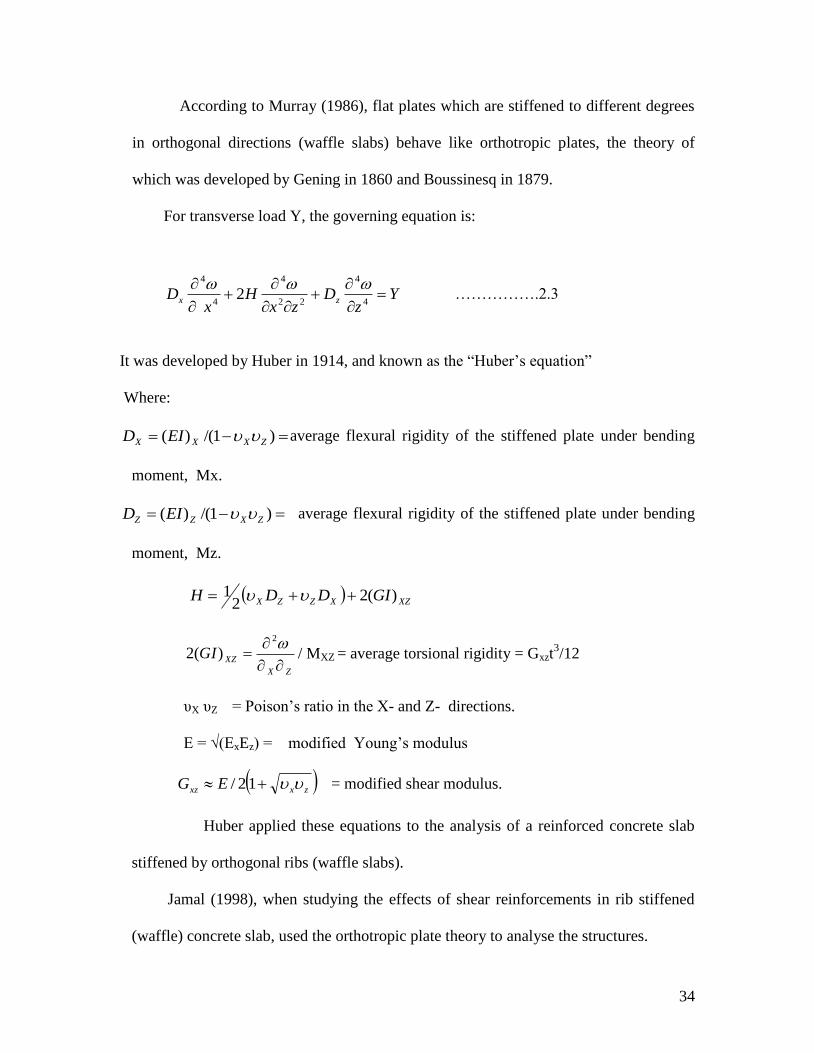
According to Murray (1986), flat plates which are stiffened to different degrees
in orthogonal directions (waffle slabs) behave like orthotropic plates, the theory of
which was developed by Gening in 1860 and Boussinesq in 1879.
For transverse load Y, the governing equation is:
Yz
Dzx
Hx
D zx
4
4
22
4
4
4
2
…………….2.3
It was developed by Huber in 1914, and known as the “Huber‟s equation”
Where:
)1/()( ZXXX EID average flexural rigidity of the stiffened plate under bending
moment, Mx.
)1/()( ZXZZ EID average flexural rigidity of the stiffened plate under bending
moment, Mz.
XZXZZX GIDDH )(22
1
ZX
XZGI
2)(2 / MXZ = average torsional rigidity = Gxzt
3/12
υX υZ = Poison‟s ratio in the X- and Z- directions.
E = √(ExEz) = modified Young‟s modulus
zxxz EG 12/ = modified shear modulus.
Huber applied these equations to the analysis of a reinforced concrete slab
stiffened by orthogonal ribs (waffle slabs).
Jamal (1998), when studying the effects of shear reinforcements in rib stiffened
(waffle) concrete slab, used the orthotropic plate theory to analyse the structures.

35
This theory assumes that the orthotropy of the structures may be replaced by the
orthotropy of the constituent material. Although the actual structural behaviour of a
stiffened slab cannot be entirely replaced by that of an equivalent orthotropic slab,
previous theoretical and experimental investigations indicated good agreement (El-
Sebakhly, 1979).
Abdul-Wahab and Khalil (2000) tested eight large-scale (1/4 scale) models of
reinforced concrete waffle slabs with varied rib spacing and rib depth to failure. The
results for the rigidities in the elastic-uncracked and elastic-cracked ranges were
compared with predicted values obtained from three different methods which included
the orthotropic plate theory. The theoretical analysis based on the conventional
orthotropic plate theory gave satisfactory predictions but involved an elaborate
procedure for determining the torsional rigidities.
2.4 Computer Programs
There have been different computer programs that were developed by different
researchers for the analysis of slabs of different shapes and configurations. It has been
discovered that most of these programs, except very few, adopted the FEM of analysis
of structures. Few of these programs are discussed here especially those that are
applicable to the analysis of waffle slabs.
2.4.1 Fortran 77
In their study of the determination of the optimum dimensions of waffle slabs for
medium size floors, Prasad et al (2005) adopted the computer program for grid
analysis, written in Fortran 77 (Formula Translation). Before adopting the said
program, waffle slabs were considered as made of grid or grillage beams. The loads

36
were distributed between longitudinal beams by bending and twisting of transverse
beams. The stiffness matrix is developed on the basis of writing joint equilibrium in
terms of stiffness co-efficients and unknown joint displacements. Straight members of
constant cross-section were considered. The deformations considered were two
orthogonal rotations in the horizontal plane and a vertical deflection at each node.
Nodal displacements in the horizontal plane and rotations along the vertical axis were
not considered keeping in view that they did not significantly contribute to the
structural behaviour and hence were ignored.
The computer analysis resulted in determining the moment, shear force and
torsion for each of the elements and deflection and rotation about the two orthogonal
axes at each of the nodes.
2.4.2 SAP 2000
Structural Analysis Program (SAP) is another computer based program that was used
to analyze both steel and concrete structures. Abdel-Karim and Mahmood (2006) used
SAP 2000 program to analyze two-way ribbed simply supported rectangular waffle slab
models, supported on beams of different stiffnesses. The analysis was done to
determine the moment and shear distribution in the ribs and beams in each direction, to
study the effect of the panel aspect ratio and the beam stiffnesses on the distribution of
moment and shear in each reaction.
The model was a grid system and the ribs were 0.5 m apart in each direction. The
slab rested on four pin supports at the corners. The used load was 2 kN/m2. The results
of the analysis gave the shear force and moment values at each joint from which the
load factors could be calculated using empirical equations such as:

37
Ma = Ca wla2 /8 ………… 2. 4
Where:
Ca= moment load factor in certain direction.
W = uniform load per metre square.
la = span length.
From the results of analysis, it was discovered that the distribution of moments
and shear in each direction depended on the panel aspect ratio and the perimeter beam
stiffnesses. In actual fact, these factors depended on the relative stiffnesses of the
perimeter beams to the slab or ribs stiffnesses and not the absolute stiffnesses of the
beams.
The beam shear load factors in each direction were calculated by the shear
values in the beams from the results of the analysis using SAP 2000. Part of the
conclusion reached was that, the results of the research could be used to calculate the
moments and shears in the perimeter beams and in the ribs in each direction for the
given aspect ratio; panel dimension; slab thickness, and beams dimensions for a given
slab load.
2.4.3 Adapt Floor Program
This program also adopts FEM for the analysis of waffle slabs. It was found to
be good for the analysis and design of post-tensioned waffle slabs, in which iron rod is
replaced by cables that are under tension as in pre-stressed concrete design. The cables
were placed between the waffle ribs and held under tension, while wire mesh was used
in the slab area (Adapt Technical Note, 2006).

38
2.4.4 SAFIR Program
In his work on membrane action in fire exposed concrete floor system, Lim (2003)
used this program to analyse slabs that are subjected to fire.
SAFIR is a non-linear finite element program which was developed at the
University of Liege, Belgium, and is based on an earlier program, CEFICOSS. It consists
of thermal and structural analysis components integrated into a single program. The
thermal analysis component was used to determine the temperature distributions of the
structural members which were used in the structural analysis. SAFIR‟s structural
analysis capabilities include 2D and 3D analysis of steel, concrete and composite
members and can account for geometrical and material non-linearity.
2.4.5 RCC Program
The Reinforced Concrete Council (RCC) also developed a computer program that
adopted the Microsoft excel package to analyse and design different civil engineering
structures based on BS 8110, and the results of this program have been found to be
appropriate.
2.4.6 ETABS
ETABS is a program that can greatly enhance an engineer's analysis and design
capabilities for structures. Part of that power lies in an array of options and features. The
other part lies on the simplicity of its use.
The basic approach for using the program is very straightforward. The user
establishes grid lines, places structural objects relative to the grid lines using points, lines
and areas, and assigns loads and structural properties to those structural objects. (For
example, a line object can be assigned section properties; a point object can be assigned

39
spring properties; an area object can be assigned slab or deck properties). Analysis and
design are then performed based on the structural objects and their assignments. Results
are generated in graphical or tabular form that can be forwarded to a printer or to a file
for use in other programs. (ETABS User guide, 2005).
2.5 The Yield Line Theory
Yield line theory is an ultimate load analysis. It establishes either the moments
in an element (e.g. a load) at the point of failure or at which an element will fail. Yield
lines not only signify the location of maximum principal moments (where yielding
occurs), but also the location of zero shears (Gohnert, 2006). The shapes and locations
of Yield zone are affected by the support structures and their rigidity (Geng et al,
2006). The theory gives a conservative estimate of strength (Ferguson, 1965). It may be
applied to many slabs both with and without beams. It can deal with openings, holes,
irregular shapes and with any support condition (Punmia et al, 2006; Chee et al 2008).
Yield line design is a plastic method: it is different from „normal‟ elastic method
(Kennedy and Goodchild, 2004).The technique requires the postulation of a
kinematically admissible yield-line or fracture pattern from which the corresponding
collapse load is determined through the principle of virtual displacements (Ramsay and
Johnson, 1997).
2.5.1 Energy dissipation
In order to calculate the load-carrying capacity from an upper bound solution, the
energy dissipation has to be known. In yield line theory, it is the energy dissipated that
is used in the analysis of the slabs, because both the external energy and internal energy
dissipated must be considered.

40
Gudmand-Høyer (2003) calculated dissipation in a yield line on the basis of
Coulomb yield condition for concrete in order to verify K.W. Johansen‟s method. An
effort was made to evaluate the error made using Johansen‟s proposal for orthotropic
rectangular slabs and it was found that the method is sufficiently correct for practical
purposes. Also, for deflected slabs that are believed to have a high load carrying
capacity, it was assumed that the axis of rotation corresponds to the neutral axis of a
slab part and dissipation was found from the moment capacities about these axes. The
Johansen‟s proposal was also used to find the load carrying capacities in these cases.
He compared his results with that of numerical calculations of the dissipation and
generated some numerical equations for energy dissipation in slabs, based on
contribution from concrete and the reinforcements. Some of the equations are shown
below in conjunction with Figures 2.2, 2.3 and 2.4.
If the axes of rotation for two slab parts are not at the same depth measured
from the slab surface, the relative displacement discontinuity is no longer perpendicular
to the yield line. The angle between the displacement discontinuity and the yield line
changes with the depth from the slab surface and this must be taken into account when
calculating the dissipation (Figure 2.2).

41
Figure 2.2: Yield line from the angle of a slab ( Source: Gudmand-Hoyer 2003)

42
Figure 2.3: Displacement for slab parts ( Source: Gudmand-Hoyer 2003)

43
Figure 2.4: Geometry relation between rotations (Source: Gudmand-Hoyer 2003)

44
2.5.2 The contribution from the concrete:
The concrete contribution from the yield line was calculated from the dissipation
formulas for plane stress assuming a modified Coulomb material. Setting the tensile
strength of concrete to zero, the contribution to the dissipation (per unit length) from
the concrete was calculated as:
Wc= dxufc
h
))sin(1(2
1
0 ………… 2.5
u being the relative displacement and α the angle between the displacement and the
yield line, Figure 2.3.
But u and α depend on z, which is the depth from the top surface to the point
considered. u1 and uII are the displacements of slab part I and II, respectively, u was
calculated as:
)cos(222
1 wuuuuu IIIII …………. 2.6
The angle between the displacement and the yield line α varies with respect to uI and uII
depending on whether they are positive or negative.
The relationship between the two rotations about I and II were found from the
geometrical conditions demanding the same displacement at a point of yield line.
From Figure 2.4, the rotations may be calculated as:

45
)sin( vw
I
…………. 2.7
)sin(v
II
Here ω is the rotation of slab part line about an axis along the yield line.
In the calculation of the displacement, it was assumed that the rotation is small and
the displacement may therefore be calculated as the product of rotation and the height.
The displacements uI , uII and u was calculated as:
h
z
h
h
vwh
u
h
z
h
h
vwhu
II
II
)sin(
1
)sin(
…………… 2.8
h
z
h
h
vh
u
h
z
h
h
vhu
IIII
IIII
)sin(
1
)sin(
………….. 2.9
.

46
Inserting (2.8) and (2.9) into (2.6) leads to:
)cos()sin()sin(
2
)sin()sin(
22
wh
z
h
h
vh
h
z
h
h
vwh
h
z
h
h
vh
h
z
h
h
vwh
u
III
III
………2.10
)sin()sin(
)cos(2
)sin()sin(
22
vvw
wh
z
h
h
h
z
h
h
v
h
z
h
h
vw
h
z
h
h
h
uIIIIII
The angle α varies and if the situation in which:
(uI > 0 & uII > 0): is considered, then α can be calculated as:
uu
uuuArcv
II
III
2cos
2
222 ………2.11
It is seen that the contribution to the dissipation from the concrete is a function of both
the position of the axis of rotation hI , hII, and h, the rotation ω and the compressive
strength, cf . The dissipation may be calculated in a dimensionless form as:
1
02))sin(1(
2
1
h
zd
h
u
fh
W
c
c
……………… 2.12

47
2.5.3 Contribution from reinforcement
Gudmand-Høyer went further to determine the contribution from the
reinforcement, based on Figure 2.5. If the reinforcement is placed in a direction
perpendicular to the axis of rotation at a distance from the slab surface as shown in
Figure 2.5, the contribution from the reinforcement to the dissipation per unit length
becomes:
cIIIIIIsIIcIIIIs
cIIIsIcIIsIS
hhAhhhAv
hhAhhhAvwW
,,2
,,
cos
cos
…………… 2.13
Where ωI and ωII are the rotations about axis I and II, respectively. These are
determined in Equation 2.6 and the expression may be written as:
h
h
h
h
h
h
h
h
v
h
h
h
h
h
h
h
h
vwfh
W
cIIIIII
IIcIIII
cIII
IcII
c
s
,0,0
,0,02
1tan
1
1tan
1
…………… 2.14
If the corner is right-angled the dissipation becomes:
h
h
h
h
h
h
h
h
v
h
h
h
h
h
h
h
hv
fh
W
cIIIIII
IIcIII
clII
IcII
c
s
'
,0,0
''
,0,02
1tan
1
1tan
………….2.15
Finally, the results from the theoretical equations derived were compared with
those obtained from laboratory test specimens, where some slabs were loaded to failure.

48
It was discovered that the theoretical load – carrying capacity was too high. This
phenomenon was ascribed to the fact that concrete does not behave entirely according
to plastic theory and an effectiveness factor was proposed to make the theory reliable.
Beside the load-carrying capacity, it was discovered that the deflection was
wrong. Not only wrong when it came to numerical value, but also when it came to the
relationship between axial force and deflection. However, the comparison with test
results showed that the theory developed may be used if the deflection at failure is
known and a proper effectiveness factor is introduced. But if deflection at failure is not
known, a conservative simplified method, which will lead to a large underestimation
for low axial forces was proposed, the method was therefore recommended as rough
estimate.

49
Figure 2.5: Reinforcement arrangement

50
2.6 Isotropic and Orthotropic Slabs
The arrangement of reinforcements in slabs has given rise to both isotropic and
orthotropic slabs. An isotropic slab is one with the same amount of bottom reinforcement
both ways. This is because the yield moments on both ways are equal, and by assuming
equal effective depth, this type of slab is easy to deal with when using the yield line
analysis and design method. Orthotropic slabs have different amounts of reinforcements
in the two directions; in this case, the yield moments in both axes are mutually
perpendicular to each other (Nilson, 1997: Buyukozturk, 2004).
According to Kennedy and Goodchild (2004), the analysis of such orthotropic slabs
can be done using the affine transformation. In these, the stronger direction is assumed to
have the moment capacity, M, and in the weaker direction the capacity of the slab is
assumed to be μM. The value of μ is usually based on the relative amounts of
reinforcement the designer wishes to use in the two directions. The use of μ will help to
transform the orthotropic slabs to isotropic slabs and can be treated as such, applying all
the usual formulae and methods.
2.7 Definition of Upper Bound and Lower Bound Theorem
i. The lower bound of the true collapse load is that external load for which a
distribution of moments can be found satisfying the requirements of equilibrium and
boundary conditions so that the moments at any location do not exceed the yield moment.
ii. The upper bound of the true collapse load is that external load for which the
internal work done by the slab for a small increment of displacement is equal to the
51
external work done by that external load for the same amount of small increment of
displacement.
Thus, the collapse load satisfying the lower bound theorem is always lower than
or equal to the true collapse load. On the other hand, the collapse load satisfying the
upper bound theorem is always higher than or equal to the true collapse load. The yield
line analysis is an upper bound method in which the predicted failure load of a slab for
given moment of resistance (capacity) may be higher than the true value. Thus, the
solution of the upper bound method (yield line analysis) may result into unsafe design if
the lowest mechanism could not be chosen. However, it has been observed that the
prediction of the most probable true mechanism in slab is not difficult. Thus, the solution
is safe and adequate in most of the cases (Kharagpur, 2009).
2.8 Difference in Load Distribution in Waffle Slabs and Solid Slabs
Load distribution in waffle slabs and solid slabs are different due to the
orientation of these slabs. Waffle slabs have hollows in between the slabs, while solid
slabs have no hollow in between. The arrangement of reinforcements in both slabs is
different as a result of the hollow in the waffle slabs. Due to the arrangements of
reinforcement and the span ratio of solid slab, there is possibility for one-way slab,
however, waffle slabs do not have a one-way slab because of the reinforcement
orientation and the presence of ribs within the slab. In a typical one-way slab, the floor
comprises beams spanning in one direction between columns and a slab spanning
between them. The system is designated as one-way slab because all loads in the slab
are transferred primarily in one direction (to the beams), since the transverse slab span
is infinite.

52
For a typical two-way slab, the floor comprises beams spanning both directions
between columns, and a slab framing between the beams. The system is designated
two-way because, in a situation where the aspect ratio of the slab has a value near unity,
the slab transfers load to the beams in two directions. This type of floor system is
generally quite efficient.
2.8.1 Load path designation in waffle slabs
In waffle slabs, loads are transferred from the slabs to the ribs and to the
perimeter beams. Abdel-Karim and Mahmood (2006), when investigating the effect of
beam stiffnesses on the load distribution in waffle slabs, was able to discover that the
distribution of moments along the parallel ribs in the short and long directions depends,
on the panel aspect ratio, the relative stiffness of the slab ribs and on the beams on
which these ribs are supported.
From the model analysis of slabs, using SAP2000, the following observations
were made. It was noticed that, as the beam stiffness was increased, the shear load
factor in the short direction increased for a specified panel aspect ratio. Also, as the
panel aspect ratio was increased, the beam shear load factor increased in the short
direction and decreased in the long direction. It was also observed that moments varied
in each direction along the panel width. It was seen that edge strip ribs had larger
moments than the middle strip ribs for beams with small cross section (moment of
inertia: stiffness) and the middle strip ribs had larger moments than the edge strip ribs
for larger beams cross section(moment of inertia: stiffness). Hence, the ribs gave
different bending moments and shear forces in each direction as a result of varying
stiffnesses. The orientation and the amount of the reinforcement provided depended on
53
the bending moments (the function of the reinforcements is to resist the bending
moment).
2.8.2 Load path designation in solid slabs
Reinforced concrete is very unique in it behaviour, and this has made it popular
as construction material. In solid slabs; at flexural failure, concrete slabs develop hinge
lines. A hinge line causes much of the reinforcement passing through it to resist the
moment along it length, contributing to the safety of the slab.
Once a slab has cracked, the reinforcement determines the manner in which the
applied load is resisted; it is the orientation and the amount of reinforcement that
govern the path that the load takes to the supports (Aalami, 2005).
Prior to the calculation of the design moments and shears, the first thing that must
be considered is to anticipate the load path, which set the orientation and position of the
reinforcement. Sivagamasundari and Kumara, 2008, opined that the major work of the
longitudinal reinforcement is to provide flexural strength for the concrete slab. For
example, in a solid two-way slab, the function of the distribution bar is to distribute the
load from the slab to the bottom or main bar, while the bottom bar will distribute the
load to the supports at the edges of the slab, both the distribution and main bars are
designed for in this type of slab. The amount of bending moment in each direction will
depend on the ratio of the two spans and the condition of restraint at each support
(Mosley and Bungey, 1990), while in one-way slab it is only the main bars that is
designed, although appropriate provision is made for distribution bar in this type of
slab. Top (torsion) reinforcement is provided at the supports or edges of slabs to
prevent cracks as concrete is known to be weak in tension (BS 8110, 1997).
54
CHAPTER THREE
METHODOLOGY
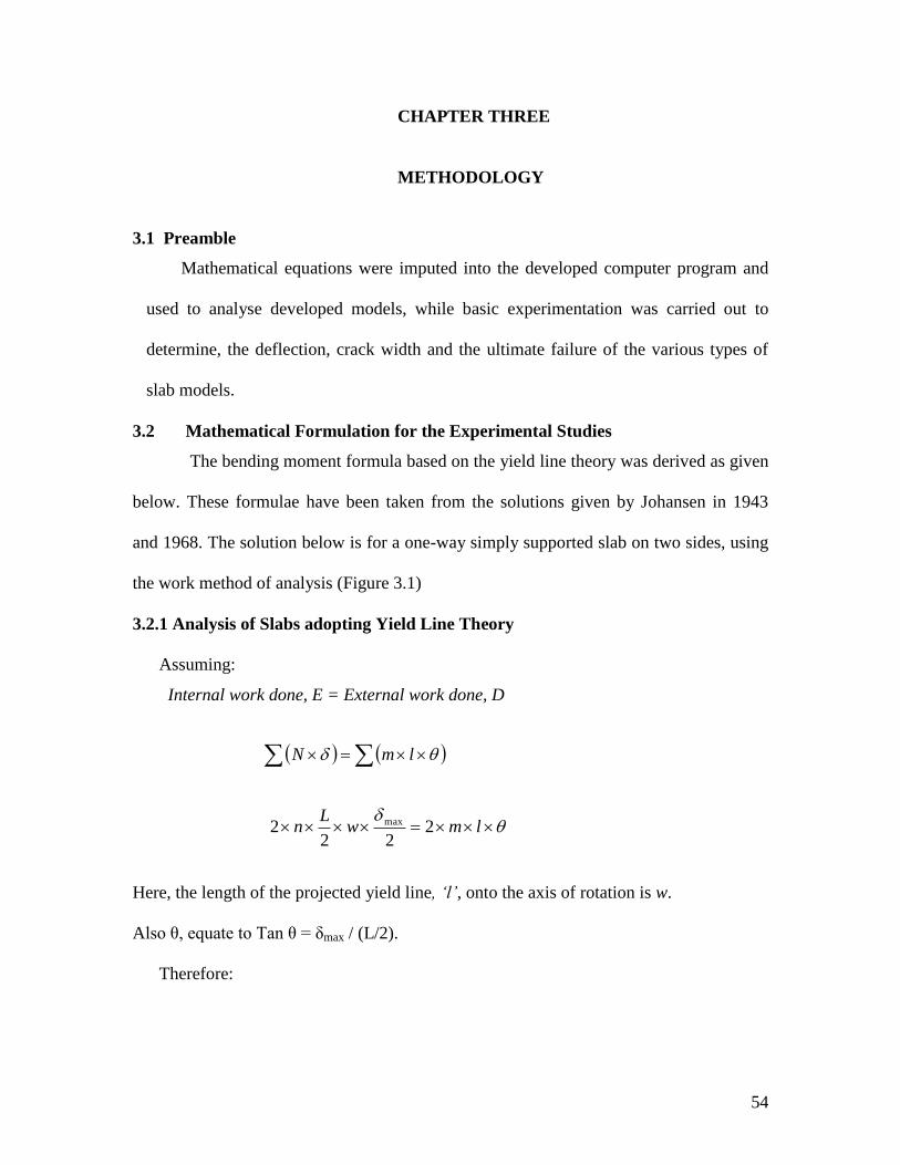
3.1 Preamble
Mathematical equations were imputed into the developed computer program and
used to analyse developed models, while basic experimentation was carried out to
determine, the deflection, crack width and the ultimate failure of the various types of
slab models.
3.2 Mathematical Formulation for the Experimental Studies
The bending moment formula based on the yield line theory was derived as given
below. These formulae have been taken from the solutions given by Johansen in 1943
and 1968. The solution below is for a one-way simply supported slab on two sides, using
the work method of analysis (Figure 3.1)
3.2.1 Analysis of Slabs adopting Yield Line Theory
Assuming:
Internal work done, E = External work done, D
lmN
lmwL
n 222
2 max
Here, the length of the projected yield line, ‘l’, onto the axis of rotation is w.
Also θ, equate to Tan θ = δmax / (L/2).
Therefore:

55
2
222
2 maxmax
Lmw
nLw
Figure 3.1: Simply supported one-way slab

56
L
mnL 4
4
2
Rearranging
8
2nLm ……………. 3.1
For two way slabs, the equation can be developed using Fig 3.2, as follows,
(Kong and Evans, 1987):
Assuming the slab measures b and L.
LmN
DE
E = external energy.
E =
LbLbN )21(
2
1
3
12
236
NbL
……………….3.2
D= internal energy.
Energy dissipation for yield line AE
L
b
b
Lm
2/
2/
Energy dissipation for yield line EF

57
2/
)21(2
b
Lm
Figure 3.2: Yield lines on two-way simply supported slab

58
Therefore, total energy dissipation for yield lines AE, DE, BF, CF, and EF
= 2/
)21(2
2/
2/4
b
Lm
L
b
b
Lm
)21(2 2
m (Where λ = l/b) …………. 3.3
Equating (3.2) and (3.3)
D = E
)23(6
)21(2 2
NbLm
2
2
21
)23(.
12
NLm ………….. 3.4
Equations 3.1 and 3.4 have been simplified by Kennedy and Goodchild (2004), to
accommodate different boundary conditions expected in a slab. Equation 3.1 was
simplified to 3.5, while 3.4 became 3.6. Furthermore, equation 3.6 has been modified
in this work to equation 3.7, in order to take care of the conservative nature of yield
line theory in solid slabs, (Akinyele 2011). Equations 3.5 and 3.7 were therefore
adopted in the computer program in Tables 3.1, 3.2 and 3.3.
221
2
112 ii
nLm
………….3.5

59
r
r
r
r
rr
b
a
a
b
banm
18
………………3.6
)(
18
vk
b
a
a
b
banm
r
r
r
r
rr
…………………..3.7
Where:
N = load acting within a particular region (kN)
= vertical displacement of the load N on each region expressed as a fraction of
Unity (m)
m = ultimate design moment of resistant for the slab (kNm)
L = length of slab (m)
θ = rotation of the region about its axis of rotation (m/m)
n = the ultimate uniformly distributed load (kN/m2)
ar = reduced short span dimension
br = reduced long span dimension
k = is a constant = 1
v = is a variable = 0 < 0.5
i = the fixity ratio at supports, e.g i1, i2.
If : i1 = i2 = 1, that support is a continuous support
And i1 = i2 = 0 that support is a simple support.

60
Table 3.1: Template for the computer analysis and design of simply supported
waffle slab adopting the yield line theory.
References Calculation/output
1 ANALYSIS AND DESIGN OF WAFFLE
SLABS USING THE YIELD LINE
THEORY
2 CODE BS. 8110 PARTS 1 1997.
3 Designed by: AKINYELE J.O
4 Simply supported on all Four Sides
5 Slab Long Span (ly) (m) 0.00
6 Slab Short Span (lx) (m) 0.00
7 Rib Width (mm) 0.00
8 Distance between ribs on Long Span (m) 0.00
9 Distance between ribs on Short Span (m) 0.00
10 Depth of Slab portion (mm) 0.00
11 Depth of ribs (mm) 0.00
12 Total depth of Slab (mm) =SUM(H10,H11)
13 Effective depth of slab (mm) =H10-H29
14 Slab dead load (kN/m2) =H10*24*10^-3*1.4
15 Imposed load on Slab (kN/m2) 0.00
16 Finishes and partition loads 0.00
17 Total load on slab (kN/m2) = SUM(H14:H15:H16)
18 For discontinuous supports, fixity 0.00
19 For continuous supports on any side, fixity 1
20 Fixity ratio for short span left. I1 0.00
21 Fixity ratio for long span bottom. I2 0.00
22 Fixity ratio for short span right. I3 0.00
23 Fixity ratio for long span top. I4 0.00
24 Reduced side ar =2*H6/(SQRT(1+H21)+SQRT(1+H23))
25 Reduced side br =2*H5/(SQRT(1+H20)+SQRT(1+H22))
26 Bending moment in slab (kNm) =1.0*H17*H24*H25/(8*(1+(H25/H24)+(H24/H25)))
27
28 DESIGN
29 Cover to reinforcement (mm) 0.00
30 Concrete characteristic strength (N/mm2) 0.00
31 Steel characteristic strength (N/mm2) 0.00
32 Maximum lever arm factor 0.95

61
33 Maximum K-value 0.156
34 Moment M =H26*1.0E06
35 K-value =H34/(H30*1.0E03*H13^2)
36 Lever arm factor =0.5+SQRT(0.25-H35/0.9)
37 Used Lever arm =MIN(H32,H36)
38 Area of Steel (mm2) =H34/(0.95*H31*H37*H13)
39 PROVIDE=
40 ANALYSIS & DESIGN OF RIBS
41 Adopting Rankine Grashoff theory
42 Number of ribs on long span 0.00
43 Number of ribs on short span 0.00
44 Weight of slab (kN/m2) =H17
45 Total load on slab (kN) =H44*H5*H6
46 Weight of ribs kN/m =(H7*H11)*1.0E-06*24
47 Total weight of ribs on long span (kN) =H42*H46*H5
48 Total weight of ribs on short span (kN) =H43*H46*H6
49 Total weight of Finishes (kN) =H5*H6*1.0
50 Total Live load (kN) =H5*H6*1.5
51 Total load on grid floor (kN) =H45+H47+H48+H49+H50
52 Q= load per area (W2) =H51/(H5*H6)
53 Denominator for Qx and Qy =SUM(H5^4,H6^4)
54 Load sheared on short span Qx (kN/m2) =H52*(H5^4/H53)
55 Load sheared on long span Qy (kN/m2) =H52*(H6^4/H53)
56 Moment on short span Mx (kNm) =(H54*H9*H6^2)/8
57 Moment on Long Span My (kNm) =(H55*H8*H5^2)/8
58 Shear force on short span Vx (kN) =(H54*H8*H6)/2
59 Shear force on long span Vy (kN) =(H55*H9*H5)/2
60 DESIGN
61 Steel characteristic strength (N/mm2) 0.00
62 Short span design moment (kNm) =H56*1.0E06
63 Cover to ribs 0.00
64 Effective depth of ribs =H11-H63
65 K-value =H62/(H30*H7*H64^2)
66 Lever arm factor =0.5+SQRT(0.25-H65/0.9)
67 Used lever arm =MIN(H66,H32)
68 Area of steel (mm2) =H62/(0.95*H61*H67*H64)
69 PROVIDE

62
70 Long span design moment (kNm) =H57*1.0E06
71 K-value =H70/(H30*H7*H64^2)
72 Lever arm factors =0.5+SQRT(0.25-H71/0.9)
73 Used laver arm =MIN(H72,H32)
74 Area of steel (mm2) H70/(0.95*H61*H73*H64)
75 PROVIDE
76 END DESIGN

63
Table 3.2: Template for the computer analysis of simply supported waffle slab
adopting the yield line theory (3 sides simply supported)
References Calculation / output
1 ANALYSIS AND DESIGN OF WAFFLE
SLAB USING THE YIELD LINE THEORY
2 CODE B.S. 8110 PART 1 1997.
3 Designed by: Akinyele J.O
4 Supported on 3-sides
5 Slab long Span (ly) (m) 0.00
6 Slab short Span (lx) (m) 0.00
7 Depth of slab part (mm) 0.00
8 Distance between ribs on long span (m) 0.00
9 Distance between ribs on short span (m) 0.00
10 Rib width (mm) 0.00
11 Depth of ribs (mm) 0.00
12 Total depth of slab (mm) =SUM(H7,H11)
13 Cover to reinforcements (mm) 0.00
14 Effective depth of slab (mm) =H7-H13
15 Slab Dead load (kN/m2) =H7*24*10^-3*1.4
16 Slab Imposed load (kN/m2) 0.00
17 Finishes and Partition loads 0.00
18 Total load on Slab (kN/m2) =SUM(H15:H16:H17)
19 CASE 1 = h1 + h2 < b
20 Fixity for 1st short Span I1 0.00
21 Fixity for supported long span I2 0.00
22 Fixity for 2nd
short span I3 0.00
23 Reduced span br =2*H5/(SQRT(1+H20)+SQRT(1+H22))
24 K‟= redistribution factor =2*H6/(3*H23)
25 .h = factor to determine yield length =H6/H24+SQRT(H24^2+(H21+H23+H24/2*H6)
+1)
26 Bending moments in slab (kN.m) =1.0*(H18*H6*H23)/
8*(((H21*H23)/4*H6)+(H6/H25))
27 CASE 2 = h1+ h2 = b
28 .b‟ = dimensions =2*H6/SQRT(1+H21)
29 Bending moments in slab (kN.m) =1.0*(H18*H23*H28)/
8*(1+(H28/H23)+(H23/H28))
30 Design

64
31 Concrete characteristic strength 0.00
32 Steel characteristic strength 0.00
33 Maximum lever arm factor 0.95
34 Maximum K-value 0.156
35 Used bending moment =MAX(H26,H29)
36 Moments M H35*1.0E06
37 K-value =H36/(H31*1.0E03*H14^2)
38 Lever arm factor =0.5+SQRT(0.25-H37/0.9)
39 Used laver arm =MIN(H33,H38)
40 Area of steel (mm2) =H36/(0.95*H32*H39*H14)
41 Provide
42 Analysis and design of ribs
43 ADOPTING RANKINE GRASHOFF
THEORY
44 No of ribs on long span (ly) 0.00
45 No of ribs on short span (lx) 0.00
46 Weight of slab (kN/m2) =H18
47 Total load on slab (kN) =H46*H5*H6
48 Weight of ribs (kN/m) =(H10*H11)*1.0E-06*24
49 Total weight of ribs on long span(kN) =H44*H48*H5
50 Total weight of ribs on short span(kN) =H45*H48*H6
51 Total weight of finishes (kN) =H5*H6*1
52 Total Live Load (kN) =H5*H6*1.5
53 Total load on grid floor (kN) =H47+H49+H50+H51+H52
54 .q = load per area (m2) =H53/(H5*H6)
55 Denominator for qx and qy =SUM(H5^4,H6^4)
56 Load sheared on short span qx(kN/m2) =H54*(H5^4/H55)
57 Load sheared on long span qy (kN/m2) =H54*(H6^4/H55)
58 Moments on short span Mx (kNm) =(H56*H9*H6^2)/8
59 Moments on long span My (kNm) =(H57*H8*H5^2)/8
60 Shear force on short span Vx (kN) =(H56*H8*H6)/ 2
61 Shear force on long span Vy (kN) =(H57*H9*H5)/ 2
62 Design
63 Steel characteristic strength (N/mm2) 0.00
64 Short span design moment (kNm) =H58*1.0E06
65 Cover to ribs 0.00
66 Effective depth of ribs =H11-H65

65
67 K-value =H64/(H31*H10*H66^2)
68 Lever arm factor =0.5+SQRT(0.25-H67/ 0.9)
69 Used lever arm =MIN(H33,H68)
70 Area of steel (mm2) =H64/(0.95*H63*H66*H69)
71 Provide
72 Long span design moments (kNm) =H59*1.0E06
73 k-value =H72/(H31*H10*H66^2)
74 Lever arm factor =0.5+SQRT(0.25-H73/ 0..9)
75 Used lever arm =MIN(H74,H33)
76 Area of steel (mm2) =H72/(0.95*H63*H75*H66)
77 Provide
78 END DESIGN

66
Table 3.3: Template for computer analysis of waffle slabs, supported on two short sides, adopting the
yield line theory.
References Calculation / output
1 ANALYSIS AND DESIGN OF WAFFLE SLAB
USING THE YIELD LINE THEORY
2 CODE B.S. 8110 PART 1 1997.
3 Designed by: Akinyele J.O
4 Simply supported on two sides
5 Slab long Span (ly) (m) 0.00
6 Slab short Span (lx) (m) 0.00
7 Depth of slab part (mm) 0.00
8 Distance between ribs on long span (m) 0.00
9 Distance between ribs on short span (m) 0.00
10 Rib width (mm) 0.00
11 Depth of ribs (mm) 0.00
12 Total depth of slab (mm) =SUM(H7,H11)
13 Cover to reinforcements (mm) 0.00
14 Effective depth of slab (mm) =H12-H13
15 Slab Dead load (kN/m2) =H7*24*10^-3*1.4
16 Slab Imposed load (kN/m2) 0.00
17 Finishes and Partition loads 0.00
18 Total load on Slab (kN/m2) =SUM(H15:H16:H17)
19 Fixity for 1st support I1 0.00
20 Fixity for 2nd
support I2 0.00
21 Bending moments in slab (kN.m) =H17*H5^2/(2*(((SQRT(1+ H19)) +
(SQRT(1+H20)))^2))
22 Design of slab
23 Concrete characteristic strength 0.00
24 Steel characteristic strength 0.00
25 Maximum lever arm factor 0.95
26 Maximum K-value 0.156
27 Moments M =H21*1.0E06
28 K-value =H27/(H23*1.0E03*H14^2)
29 Lever arm factor =0.5+SQRT(0.25-H28/ 0.9)
30 Used lever arm =MIN(H25,H29)
31 Area of steel (mm2) =H27/(0.95*H24*H30*H14)
32 Provide

67
33 ANALYSIS & DESIGN OF RIBS
34 Adopting Rankine Grashoff theory
35 Number of ribs on long span 0.00
36 Number of ribs on short span 0.00
37 Weight of slab (kN/m2) =H18
38 Total load on slab (kN) =H37*H5*H6
39 Weight of ribs kN/m =(H10*H11)*0.000001*24
40 Total weight of ribs on long span (kN) =H35*H39*H5
41 Total weight of ribs on short span (kN) =H36*H39*H6
42 Total weight of Finishes (kN) =H5*H6*1
43 Total Live load (kN) =H5*H6*1.6
44 Total load on grid floor (kN) =H38+H40+H41+H43+H42
45 Q= load per area (m2) =H44/(H5*H6)
46 Denominator for Qx and Qy =SUM(H5^4,H6^4)
47 Load sheared on short span Qx (kN/m2) =H45*(H5^4/H46)
48 Load sheared on long span Qy (kN/m2) =H45*(H6^4/H46)
49 Moment on short span Mx (kNm) =(H47*H9*H6^2)/8
50 Moment on Long Span My (kNm) =(H48*H8*H5^2)/8
51 Shear force on short span Vx (kN) =(H47*H8*H6)/2
52 Shear force on long span Vy (kN) =(H48*H9*H5)/2
53 DESIGN
54 Steel characteristic strength (N/mm2) 0.0
55 Short span design moment (kNm) =H49*1.0E06
56 Cover to ribs 0.00
57 Effective depth of ribs =H11-H56
58 K-value =H55/(H23*H10*H57^2)
59 Lever arm factor =0.5+SQRT(0.25-H58/0.9)
60 Used lever arm =MIN(H59,H25)
61 Area of steel (mm2) =H55/(0.95*H54*H60*57)
62 PROVIDE
63 Long span design moment (kNm) =H50*1.0E06
64 K-value =H63/(H23*H10*H57^2)
65 Lever arm factors =0.5+SQRT(0.25-H64/0.9)
66 Used laver arm =MIN(H65,25)
67 Area of steel (mm2) =H63/(0.95*H54*H66*H57)
68 PROVIDE
69 END DESIGN

68
3.2.2 Analysis of ribs adopting the Rankine Grashoff Formulae
The Rankine Grashoff formulae were adopted for the analysis of the rib portion of the
waffle slab, the formulae are very simple and they considered both the bending moments
and shear forces at the ribs which are designed as flanged sections. This formulae were
developed by Grashoff. (Krishna Raju, 1988).
The parameters for the equation are as follows;
- a1 and b1 = are the spacing of the ribs on the short and long span respectively.
- q = total load per unit area
- q1 and q2 = the load shared on the short and long span respectively
- a = Shorter dimension of grid
- b = Longer dimension of grid
- Mx and My are moments on the short - and long- span ribs respectively
- Qx and Qy are the shear forces on the short and long span ribs respectively.
Grashoff equations were derived as follows:
44
4
1ba
bqq and
44
4
2ba
aqq …………….. 3.8
The bending moment were given as shown below:
8
2
11 abqM x and
8
2
12 baqM y …………………3.9
The shear force equation was given as shown below:
2
11 abqQx and
2
12 baqQy …………………. 3.10

69
3.3 Computer Program for the Analysis and Design of Waffle Slab.
The computer program YLRGT for the analysis and design of waffle slab was
developed adopting the Microsoft excel package. The complete templates for the program
are shown in Tables 3.1, 3.2 and 3.3.
3.4 Materials
3.4.1 Concrete
The ordinary Portland cement was used in the concrete, mixed with fine aggregate
(sand) and coarse aggregate (granite), the maximum size of the granite was limited to
9.5 mm (3/8 in). This is because of the small models used and narrow dimensions
between the sides of the form work.
The combined aggregate were prepared based on the recommendation of BS
1881 Part 116; natural clean water without contamination was used in the concrete mix.
Water cement ratio of 0.5 was selected to achieve the required 28-day concrete strength
of 20 N/mm2.
, as was used in the case study; concrete samples were taken for the cube
test (BS 1881, 1971).
3.4.2 Reinforcement
The steel reinforcements used in the case study were, 2Y20 mm for main ribs, 2Y12
mm for minor ribs, and Y10-200 mm c/c distribution steel in the slab for panels P1, P5,
and for P3, (Figure 3.3), 2Y16mm was adopted for the main ribs and 2Y12 mm for
minor ribs. When ratio 1:4 was adopted for the model, the main reinforcement became
1Y8 mm for the major ribs and 1R6 mm steel for the minor ribs, while plain 2.5 mm
/D98 wire mesh was used in the slab as distribution steel.
For panels P2, P4 and P6, in the prototype, 2Y12 mm was used in the major and
minor ribs respectively. And Y8-200 mm c/c distribution steel was used in the slab.
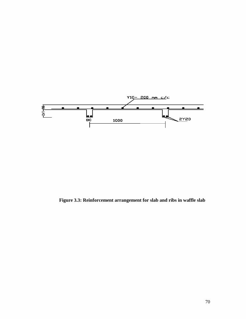
70
Figure 3.3: Reinforcement arrangement for slab and ribs in waffle slab
71
Adopting ratio 1:4, the major and minor ribs became 1R6 mm steel as main steel, while
2.5 mm/D98 wire mesh was also adopted as distribution steel in our models. The wires
were cut to sizes and cleaned from rust using metal brush, in such a way to keep the
bond forces that will be developed between the interface of concrete and steel. These
bond forces are essential to prevent slip from occurring at the interfaces (Nilson and
Winter, 1991).
3.5 Description of the Specimens
A total of sixty model samples were used for the experiment. Thirty samples
each were used for the waffle and solid slabs respectively. These samples were
subjected to axial loads, five samples per panel. Six types of panels were used for each
of the waffle slabs and solid slabs respectively. Table 3.4 shows the geometric
properties of waffle slab prototypes, while Tables 3.5 and 3.6 show the scaled down
geometric description of the panel properties of the models for both the waffle and solid
slabs respectively.
Different support conditions were adopted for all the slabs. Slabs W1, W3, S1
and S3 were supported on the two short sides, slabs W5, W6, S5 and S6 were all
supported on three sides, i.e. two short and one long sides, while slabs W2, W4, S2 and
S4 were supported on all the four sides. The reason for the different support conditions
is to apply eccentric loading in the slabs.
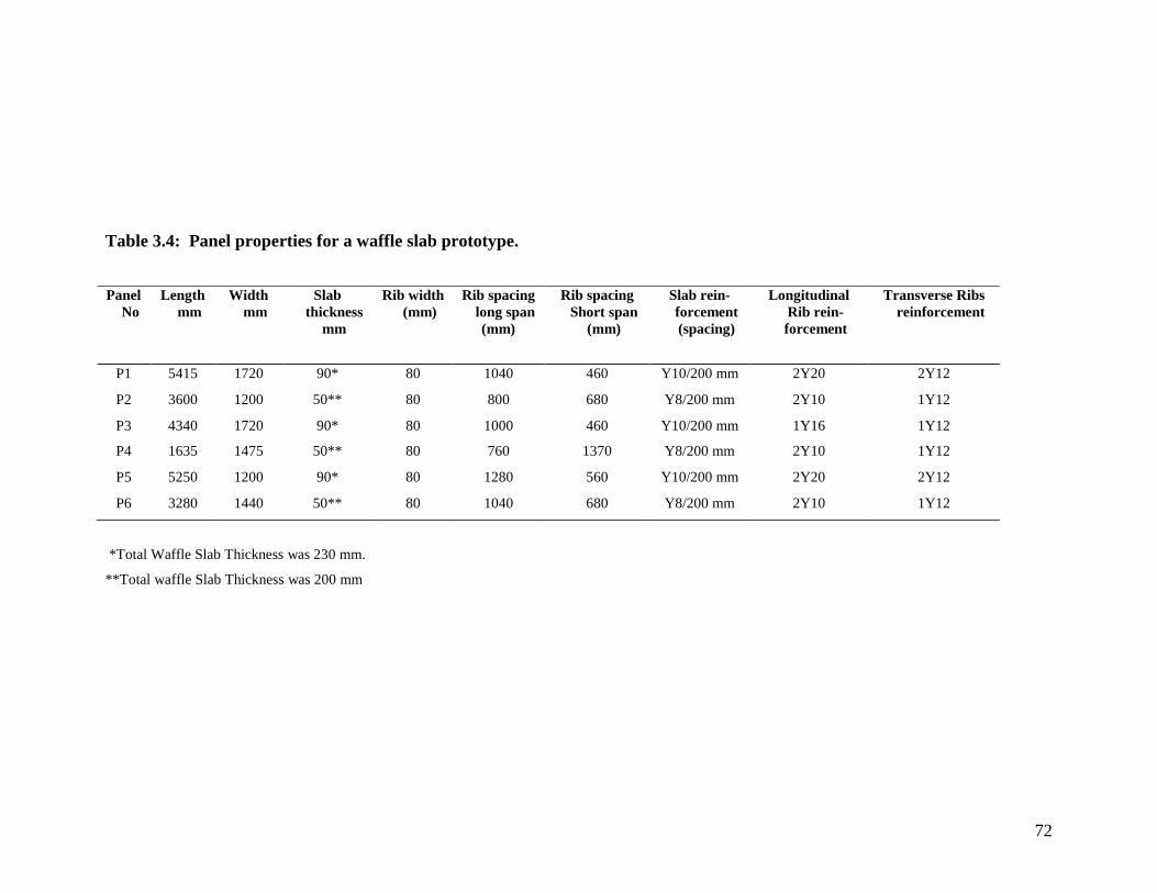
72
Table 3.4: Panel properties for a waffle slab prototype.
Panel
No
Length
mm
Width
mm
Slab
thickness
mm
Rib width
(mm)
Rib spacing
long span
(mm)
Rib spacing
Short span
(mm)
Slab rein-
forcement
(spacing)
Longitudinal
Rib rein-
forcement
Transverse Ribs
reinforcement
P1 5415 1720 90* 80 1040 460 Y10/200 mm 2Y20 2Y12
P2 3600 1200 50** 80 800 680 Y8/200 mm 2Y10 1Y12
P3 4340 1720 90* 80 1000 460 Y10/200 mm 1Y16 1Y12
P4 1635 1475 50** 80 760 1370 Y8/200 mm 2Y10 1Y12
P5 5250 1200 90* 80 1280 560 Y10/200 mm 2Y20 2Y12
P6 3280 1440 50** 80 1040 680 Y8/200 mm 2Y10 1Y12
*Total Waffle Slab Thickness was 230 mm.
**Total waffle Slab Thickness was 200 mm

73
Table 3.5. Panel properties of the waffle models. (Scale ¼)
Panel
No
Length
mm
Width
mm
Slab
thickness
(mm)
Rib width
(mm)
Rib spacing
Long span
(mm)
Rib spacing
short span
(mm)
Slab rein-
forcement
(spacing)
Longitudinal
Rib rein-
forcement
Transverse Ribs
reinforcement
W1 1353 430 22.5* 20 260 135 2.5/D98 1Y8 1R6
W2 900 300 12.5** 20 200 170 2.5/D98 1R6 1R6
W3 1085 430 22.5* 20 250 135 2.5/D98 1R6 1R6
W4 407 364 12.5** 20 190 344 2.5/D98 1R6 1R6
W5 1312 300 22.5* 20 320 140 2.5/D98 1Y8 1R6
W6 860 360 12.5** 20 260 170 2.5/D98 1R6 1R6
*Total Waffle slab Thickness was 58 mm.
**Total Waffle slab Thickness was 50 mm.
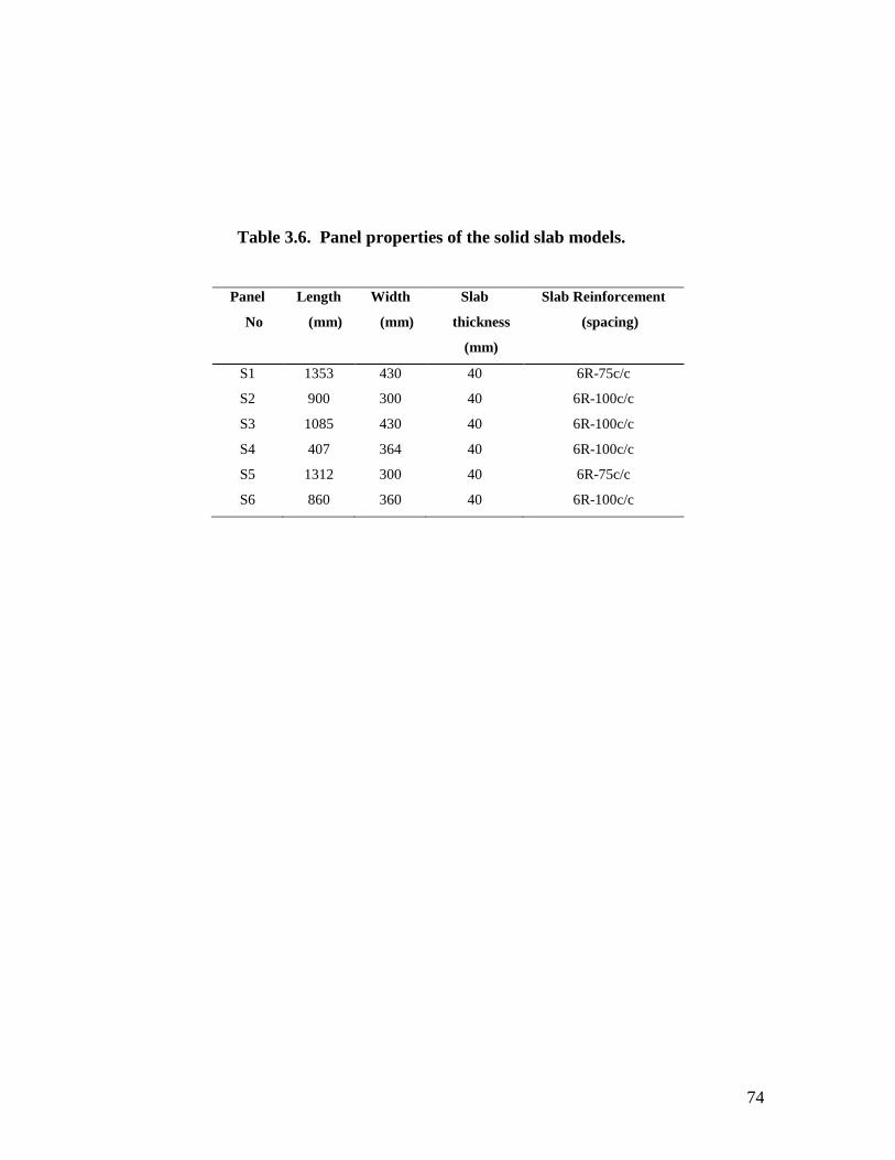
74
Table 3.6. Panel properties of the solid slab models.
Panel
No
Length
(mm)
Width
(mm)
Slab
thickness
(mm)
Slab Reinforcement
(spacing)
S1 1353 430 40 6R-75c/c
S2 900 300 40 6R-100c/c
S3 1085 430 40 6R-100c/c
S4 407 364 40 6R-100c/c
S5 1312 300 40 6R-75c/c
S6 860 360 40 6R-100c/c
75
3.5.1 Modelling of specimens
The areas of reinforcements for the models were obtained from equation 3.11, and
the equation is derived below.
Adopting dimensional analysis, (Rajput, 1998: Bankole, 2007).
Using stresses relationship between the prototype and the model,
For Prototype.
Stress ζ = Area
Force = Mp . Lp
-1. T p
-2
And for the Model.
Stress ζ = Area
Force = Mm . Lm
-1. Tm
-2
Where
M = Mass
L = length
T = Time
Subscript p and m are symbol for the prototype and model respectively.
At scale 1 : 4
4. Mm . Lm -1
. Tm-2
= 1. Mp . Lp -1
. T p -2
……………………….. i
Substituting Mass as a function of reinforcement unit weight in dimensions symbol,
Unit weight = weight / Volume = δ
δ = M.L-2
T-2
M = δ L 2 T
2 ………………………. ii

76
Substituting for M in equation i,
4. (δ. L 2 T
2)m Lm
-1. Tm
-2 = 1. (δ. L
2 T
2)p Lp
-1. T p
-2 ……… iii
From equation iii:
4. δm Lm = 1. δp Lp
Lm = 4.
1..
m
pp L
…………………………….. 3.11
But Lp = Diameter of bars in the prototype
Lm = Diameter of bars in the model
δp = Characteristic strength of steel used in the prototype
δm = Characteristic strength of steel used in the model
For example, the area of the steel reinforcement for the major rib in panel P1 of the
prototype is as follows
2Y20 = 628 mm2
But for the model W1 using equation 3.11 above,
Lm = 410. 20. 1 = 5 mm
410 . 4
The bar size is 5 mm diameter (area=19.64 mm2), and since 2Y20 was required from the
prototype, hence, 2 No.5 mm diameter bar will be obtained (area= 39.27 mm2). Since
there is no 5 mm diameter bar available in the market, then 1Y8 bar (area= 50 mm2) was
adopted for the main rib of the model W1.
For the solid slab models, the reinforcement was obtained as follows:

77
The reinforcement in the prototype was calculated to be Y12- 275 mm c/c.
For panel S1,
L= 5415 mm, total length.
Hence, 19275
5415
19 bars were used,
Total area of bars per length = 113 x 19 = 2147 mm2
At scale 1 : 4 , area required = 2147 / 4 = 537 mm2
Area of 5 mm bar = 19.64 mm2, (since Y12 will give 5 mm bar from scale 1:4)
No of bar required = 537 / 19.64 = 27
Since there is no 5mm available in the market,
Adopt 6R- 75 mm c/c. (377 mm2).
Hence, Length of model = 1354mm
05.1875
1354 Say 19
19 x 28.30 = 538 mm2 area of bars required is O.K
3.6 Casting of Specimens
All specimens were cast in forms made of plywood. The voids between the ribs
were made by gluing Polystyrene blocks to the plywood form by following a marked
pattern on the plywood. The reinforcement was then placed between the Polystyrene
blocks in both directions. The reinforcement in the longer direction was placed first on
small concrete blocks (biscuit) to keep it 5 mm from the bottom of the forms. This
provided for the minimum cover required for the steel. The steel in the shorter direction
was then placed on the top of the reinforcement in the longer direction. Both layers of

78
reinforcement were tied together with thin binding wire for stability during casting of the
concrete. The wire mesh was placed and fixed properly.
The concrete was then cast, tamped and vibrated to prevent honey comb. After that,
the top surface of the concrete was given a smooth final finish with the use of hand
trowel. All specimens were moist cured for 28 days which helped the concrete to stabilize
its own properties, like compressive strength and modulus of elasticity. To determine the
compressive strength of the concrete, 150 x 150 mm concrete cubes were cast with the
specimen. These cubes were submerged in water for curing and crushed at 7, 21 and 28
days (BS 1881, 1971).
3.7 Instrumentation
The deflections of the concrete specimens for the bending test were measured by
means of a digital dial gauge with sensitivity of 0.01 mm. The dial gauges were placed at
the top of the slab and held in place by the use of steel frame clamped on to the test
machine. The crack widths were measured using a vernier caliper. Plate 1 showed both
the dial gauge and the vernier caliper.
3.8 Experimental Set-up and Procedure
The slabs were loaded using Universal tensile testing machine. The slabs were placed
on welded steel frame to give it a good support, and placed in between the loading
machine. The machine loader applies the loads to the slabs from the top.
Deflections of the slabs were measured at load increment of 1 kN, and these were
done during the loading of the concrete specimen. Crack widths were measured at failure
load. The average mean value of the five results for each of the models samples was used.

79
The bending moments of each slab were obtained using the yield line theory formulae
(equations 3.5 and 3.7.).
Plates 1 and 2 showed the precast waffle and solid slabs well stacked waiting
transportation to the laboratory. Plate 3 showed the universal tensile testing machine
while Plate 4 showed the test arrangements in the machine.

80
Plate 1: Stacked slabs.

81
Plate 2: Some samples of waffle slabs
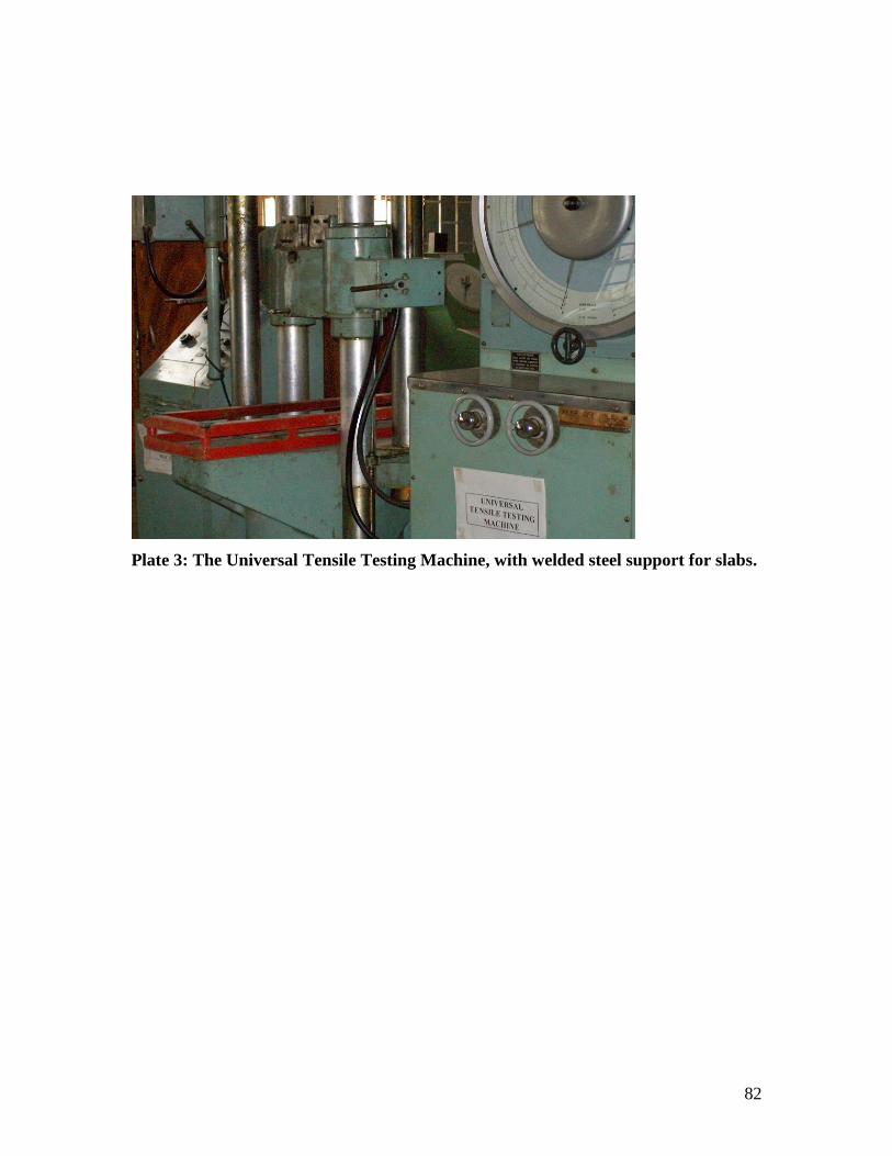
82
Plate 3: The Universal Tensile Testing Machine, with welded steel support for slabs.

83
Plate 4: Test arrangement for a slab sample
84
3.9 The Analysis of the Prototype
The Prototype was analysed by the Grillage analysis method which is mainly used
in the analysis of bridges.
In grillage analysis, the longitudinal members are arranged to represent the main
beams with the transverse members representing the deck slab and diaphragm beams. All
loads are proportioned to the grillage members (longitudinal members only) and grillage
joints before the moments, shear and torsion are calculated. The loads are applied to each
longitudinal member as uniformly distributed loads (Childs, 2008). Hence the transverse
members are neglected in this analytical method. This method may not be the most
reliable for the analysis of waffle slabs because the transverse members in the waffle slab
also carry some proportion of loads which should not be neglected. This might have led
to some of the discrepancies observed in the laboratory results.
This study adopted the Rankine Grashoff theory which accommodated loading in both
the longitudinal and transverse members of the waffle slab.
3.10 Analysis of Data
With the experimental set up above, coupled with the equations, some data were
generated at the end of the work. The results obtained from both the waffle slabs and the
solid slabs were subjected to Descriptive statistics and analysis of variance (ANOVA).
Significant means were separated using least significant difference (LSD).

85
CHAPTER FOUR
RESULTS AND DISCUSSION
4.1 Structural Response of Specimens to Loads
Waffle slabs and solid slabs were all simply supported, deflection was
observed from the dial gauge immediately loading started. The cracks emerged from the
middle of the slabs where the load was being applied and extended toward the slab edges,
the crack width continued to expand until the failure load was reached .The cracks at the
surface of the slab were very small compared to the ones formed at the slab bottom. This
is as a result of the weakness of concrete in tension as the bottom parts of the slabs are
under tension.
Deflection and the extent of cracking of a reinforced concrete slab are highly
dependent on its support conditions, nonlinear and inelastic properties of concrete and the
surrounding structure (Gilbert and Guo, 2005). The initial load at which deflection was
observed, failure load and final deflection are showed in Table 4.1, for example, W1
started deflecting at 2 kN and the initial deflection was 0.10 mm, the final deflection was
1.19 mm at 18 kN failure load, while the load at which the first crack was observed was
9 kN and the final crack width was 0.60 mm, at a failure load of 18 kN. Table 4.2,
showed the initial and final loads for the crack width of other slabs. The final crack
patterns on the slab surface are showed in Plates 5 – 12. Each crack pattern for solid slabs
depends on the support condition and loading orientation, whereas the crack pattern in
waffle slabs did not show define pattern, Plate 13 showed the crushing of a waffle slab
ribs.

86
Table 4.1: Deflection of slabs under load
Specimens Initial Load
(kN)
Failure load
(kN)
Initial deflection
(mm)
Deflection
at failure load
(mm)
W1 2.00 18.00 0.10 1.19
W2 1.00 9.00 0.34 3.64
W3 4.00 12.00 1.11 3.90
W4 1.00 6.00 1.45 6.60
W5 1.00 8.00 1.44 8.17
W6 2.00 12.00 0.43 3.28
S1 2.00 12.00 0.73 3.56
S2 1.00 7.00 1.10 9.28
S3 2.00 14.00 0.71 7..44
S4 1.00 6.00 1.19 6.44
S5 1.00 6.00 2.14 12.18
S6 2.00 10.00 0.14 3.89

87
Table 4.2: Crack properties of slabs under load
Specimens Initial crack load
(kN)
Final crack load
(kN)
Crack width
at failure
(mm)
Crack patterns
W1 9.00 18.00 0.60 Plate 5
W2 6.00 9.00 0.35 Plate 6
W3 6.00 12.00 0.34 -
W4 3.00 6.00 0.25 Plate 7
W5 4.00 8.00 0.75 Plate10
W6 7.00 12.00 0.62 -
S1 5.00 12.00 1.20 -
S2 2.00 7.00 0.75 Plate 8
S3 6.00 14.00 0.90 -
S4 2.00 6.00 0.70 Plate 9
S5 3.00 6.00 1.10 Plate 11
S6 4.00 10.00 1.30 Plate 12

88
4.1.1 General observation of structural response of specimens to load
Generally, it was observed that the crack widths on all the waffle slabs were small
compared to the corresponding solid slabs. The crack patterns in the solid slabs were
more definite than those of waffle slabs.
This was due to the presence of ribs at the bottom and was also responsible for the
small crack width and irregular crack pattern observed on the toping of the waffle slabs.
The ribs were in the tension zone and were subjected to direct tensile stresses, unlike the
solid slab where the bottom part was exposed directly to the tensile force.
In the waffle slabs, the ribs failed first before the slab portion started showing any
sign of distress. The different crack patterns formed were as a result of the type of
support (boundary) conditions that each slab was exposed to. Appendices 39 to 50 show
details of the loads, deflections and crack widths of the slabs.

89
Plate 5: Crack pattern for waffle slab W1 supported on 2 short sides

90
Plate 6: Crack pattern for waffle slab W2 Supported on all 4 sides

91
Plate 7: Crack pattern for waffle slab W4 Supported on all 4 sides

92
Plate 8: Crack pattern for Solid Slab S2 supported on all 4 sides

93
Plate 9: Crack pattern for solid slab S4 supported on all 4 sides

94
Plate 10: Crack pattern for waffle slab W5 Supported on 1 long side and 2 short
sides
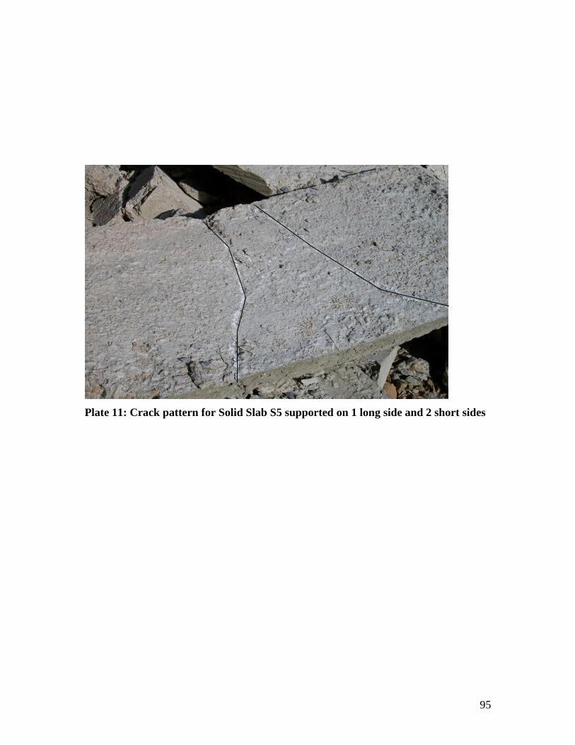
95
Plate 11: Crack pattern for Solid Slab S5 supported on 1 long side and 2 short sides

96
Plate 12: Crack pattern for Solid Slab S6 supported on 1 long side and 2 short sides

97
Plate 13: Crack pattern of a failed waffle slab bottom

98
4.2 Bending Moments of Specimens
The theoretical bending moments of the panels were compared with the
experimental bending moments. The results for that of waffle and solid slabs are
presented in Tables 4.3 and 4.4 respectively. The theoretical collapse load was obtained
using the design load of 2.0 kN/m2, Live load (for Hostels) and Dead load based on the
depth of each slab, finishes and partition. The factors of safety 1.4 for dead load and 1.6
for live load were applied.
The experimental collapse load was obtained from the results of the laboratory
work. The bending moments were obtained using the yield line theory for all the different
supports conditions such as: simply supported on two, three, and four sides respectively.
From the results in Tables 4.3 and 4.4, it was observed that the experimental
bending moments of the various panels were higher than the theoretical values (both for
waffle and solid slabs). This is in contrast with the findings of Gudmand-Høyer in his
work on yield line theory for concrete slabs subjected to axial forces, but concluded that
the findings could be a rough estimate and an effectiveness factor could be introduced to
make the findings reliable (Gudmand-Høyer 2003). Although it is expected that the
experimental results be greater than the theoretical, because the final reinforcement
provided is expected to be higher than the designed reinforcement area due entirely to the
safety of the structure. But the difference between the theoretical results and the real
results (experimental) should not be too high, since the economy of the structures is also
very important. The differences may be as a result of the following factors:
The design package used in the (Prototypes) experiment was different from the
one used in the theoretical analysis.

99
Table 4.3: Comparison of theoretical and experimental bending moments
(Waffle slab)
Theoretical Experimental
Panels
Bending Moments
(kNm)
Bending
Moments (kNm)
Deflection
(mm)
W1 2.157 5.526 1.19
W2 0.084 1.122 3.64
W3 1.653 2.880 3.90
W4 0.066 0.590 6.60
W5 0.436 0.947 8.17
W6 0.297 1.276 3.29

100
Table 4.4: Comparison of theoretical and experimental bending moments
(Solid slab)
Theoretical Experimental
Panels
Bending
Moments (kNm)
Bending Moments (kNm) Deflection
(mm)
S1 2.257 3.684 3.56
S2 0.0924 0.872 9.28
S3 1.452 3.360 7.44
S4 0.072 0.590 6.44
S5 0.459 0.710 12.18
S6 0.324 1.062 3.89
101
The theoretical results are based on ideal situations that are assumed to be perfect,
while the practical results are based on the situation on ground which may not be
as perfect as expected due to various unforeseen conditions.
The reinforcements provided to resist bending moments of reinforced concrete
were sometimes over estimated. This was evident in all the reinforcements
provided in the ribs of the prototypes. For example, panel P1 which had the
largest dimensions of 5415 mm x 1720 mm, had reinforcement of 2Y20 (628
mm2) in the long ribs and 2Y12 (226 mm
2) was provided in the short ribs. In the
model, this was scaled down to ratio (1/4), and dimension 1353 mm x 430 mm
was obtained. Using dimensional analysis, the reinforcements for the long ribs
were 1Y8 (50 mm2), and 1R6 (28 mm
2) for the short ribs (Tables 3.4 and 3.5). In
the analysis of the ribs adopting the Rankine Grashoff theory (Appendix 1), the
area of reinforcements for both long and short ribs were 3.320 mm2 and 1.136
mm2 respectively. This implies that if a reinforcement of 1R2.5 (5 mm
2) was used
for both ribs, the bending moment would be supported without causing any
structural problem. The use of 1R2.5 in the model suggested that 1Y10 (79mm2)
steel could be used in both ribs for the prototype P1. In order to reduce service
stress in the steel, 2Y10 could also be used. The reinforcements used in the ribs of
the prototype were very high and this was not economical. The reason for the high
number of reinforcements was because the grillage analytical method that was
used in the analysis of the prototype allowed excess load in the longitudinal ribs,
the method did not distribute any load to the transverse ribs (nominal
reinforcements were provided for the transverse ribs). This might have led to the

102
over reinforcement in the main ribs, thus affecting the bending moment of the
structure. The grillage method is good for the analysis of bridge decks, not for
precast waffle slab (Akinyele and Alade, 2011).
The discrepancies in the results might also be due to the fact that concrete does
not behave entirely as an elastic material (Mindes and Young, 1981; Neville,
1990). This is because, concrete was assumed to be elastic during the design
stage. The analysis and design of other slabs can be seen in Appendices 2-24.
4.2.1 Comparison of bending moments of waffle slabs and solid slabs
The results for waffle W1 and solid S1 showed that the bending moments of the
waffle slab were higher than that of the solid slabs by 33 %. Both slabs were supported
on two short sides. For W2 and S2, the waffle was 22 % greater than that of solid slab in
strength; both slabs were supported on four sides. Waffle slab W3 was 16.7% lower than
solid slab S3, although they were supported on two sides. SlabsW4 and S4 gave the same
results. However, these were supported on four sides.
The bending moments of W5 was 24.96 % higher than that of S5 while W6 was
16.67% greater than that of S6. These slabs were supported on three sides. Apart from the
slabs that gave the same results (Tables 4.3 and 4.4); it was generally observed that
waffle slabs had higher bending moments than solid slabs. This supports the advantages
of waffle slabs over solid slabs in terms of ability to support heavy loads over a long span
without increasing the depth.
This advantage was as a result of the presence of ribs in waffle slabs which act as
flanged beams within the slab system. The bulk of the tensile load was carried by the ribs
that spanned in both ways. This helped in the equal distribution of the load over the entire
103
span to the supports. The contribution of reinforcement to this advantage can not be ruled
out also, because the presence of reinforcement in the slab portion and the ribs of waffle
slabs gave it advantage over solid slabs which had reinforcement in it tensile zone only.
4.2.2 Effects of slab sizes and ribs on the bending moments of waffle slabs
The effects of the sizes of slabs on their bending moments were investigated. The
sizes of waffle slabs that were set up under the same support conditions were compared
with each other. The collapse loads (ultimate load) were used to determine the bending
moments and the following observations were made.
4.2.2.1 Comparison of Bending moments of W1 and W3
Waffle slabs W1 and W3 were both simply supported on two sides, along the small
spans while the large spans were free. From Table 3.5; it was observed that W1 has a
larger dimension than W3. The collapse load of W1 was 18 kN, the bending moment
obtained was 5.526 kNm, while for W3, the collapse load was 12 kN and bending
moment was 2.88 kNm, W1 gave a 9 kN shear force at the supports while the shear force
for W3 was 6 kN at the supports.
The above results showed that W1 has a higher bending moments than W3 despite it
long span (Theoretically, slabs with long span are expected to fail earlier than those with
short span for the same depth). The higher collapse load and moment may be attributed to
the number of ribs in slab W1 which had four equally spaced ribs on the long axis while
W3 had only three that were also equally spaced. They both had two ribs each on their
short sides.

104
4.2.2.2 Evaluation of the bending moments of W2 and W4
Waffle slab W2 had larger dimensions than W4 (Table 3.5). The collapse load of
W2 was 9 kN, and the bending moments was 1.122 kNm. The slab W4 had a collapse
load of 6 kN, and its bending moments was 0.590 kNm. W4 was smaller in size; it had
the lower collapse load and bending moments. This can be attributed to the single rib in it
soffit, unlike W2 that had 3 short ribs and two long ribs in its soffit (plate 13), and both
slabs were supported on all four sides.
4.2.2.3 Assessment of the bending moments of W5 and W6
The two waffle slabs W5 and W6 were supported on three sides, leaving one of the
long span free. W5 had an ultimate load of 8 kN, and a bending moment of 0.947 kNm,
while W6 had an ultimate load of 12 kN, and a bending moment of 1.276 kNm. It can be
observed that although W5 had the higher dimension (Table 3.5), both the ultimate load
and bending moment were lower than those of W6. While W5 had three ribs on the long
side compared to the two of W6, they both had one rib each on the shorter side.
The reason for the low bending moment of W5 can be attributed to the type of
support and the length of the long span. The length of W5 was about 1.5 times that of
W6, this created a kind of in-balance in the slab. This also had effect on the load carrying
ability of the slab since loads that were distributed to the unsupported long span area
caused the early failure of the slab. The other area of the slab that were supported could
not carry the excess load from the unsupported long span because the three ribs on the
long span were responsible for the transfer of the load from the middle of the slab to the
edge ribs. Since the edge ribs were to convey the loads to the supports, the edge rib on the
unsupported side was under greater tensile stress as it had no supports under it. The three

105
mid ribs that transfered the load from the middle of the slab acted like a point load on this
unsupported but long edge rib. The reinforcements on the edge rib could not withstand
the excess load on its rib; therefore it yielded earlier, leading to the eventual failure of the
slab system. Although W6 also reacted like W5 in terms of load distribution, it did not
yield earlier than W5 because the edge rib (long span) was shorter than that of W6.
4.2.3 Effects of slab size on the bending moments of solid slabs
The sizes of solid slabs were also investigated to determine their contribution to the
bending moment of solid slabs. Slabs with the same support conditions were compared
with each other and the results discussed below:
4.2.3.1 Relationship between the bending moments of S1 and S3
The two solid slab samples were simply supported on the two short spans and the
long spans were free. S1 was larger than S3, and both slabs were one way slab. It was
observed that the collapse load for S1 was 12 kN, while the bending moment was 3.684
kNm; S3 had 14 kN for its collapse load, while bending moment of 3.36 kNm was
generated, slab S1 had a shear force of 6 kN while S3 had 7 kN at the support
respectively (Appendices 19 and 21).
From the above results, it was observed that both slabs had different collapse
loads, but the bending moment generated in S1 was higher than S3 when the analytical
method of a uniform load over part of a simply supported slab was used. This difference
was because the span/ depth ratio of S1 was higher than that of S3, so that an appropriate
reinforcement could be provided to resist the excess bending moment generated as a
result of the longer span in the slab. If the result is compared to the corresponding waffle

106
slabs W1 and W3, the absence of ribs that would have provided additional rigidity to the
solid slab also contributed to the lower collapse load in S1.
4.2.3.2 Difference in the bending moments between S2 and S4
The collapse load for S2 was 7 kN, and its bending moment was 0.872 kNm. Solid
slab S4 gave a collapse load of 6 kN, and bending moment of 0.590 kNm. Both slabs
were supported on four sides. The bending moment of S4 was 1.4 times smaller when
compared to that of S2. The above results had shown that the size of a slab had a way of
contributing to the amount of bending moment generated in the structure.
4.2.3.3 Comparison of the bending moments of S5 and S6
The results in slabs S5 and S6 showed that S5 had a collapse load of 6 kN and a
bending moment of 0.710 kNm. The result of S6 gave a collapse load of 10 kN, while its
bending moment was 1.062 kNm.
Both slabs were supported on three sides while one large side was free. They both
had the same depth, and were both one way slabs. This condition gave rise to the lower
collapse load of the longer slab S5. The in-balance was a result of one long side not
supported, causing the tensile or bottom parts of the slabs to be over stressed, especially
the non-supported slab edge. It can be recalled that all loads were transferred from the
middle of the slabs where the load was being applied to the edges. Since there were no
ribs on this edge as it was in waffle slabs, the bottom reinforcement in this part of the slab
yielded easily, leading to the eventual failure of the entire slab system. It was the same
failure mode that happened in slab S6, but the amount of failure was lower when
compared with S5.
107
4.3 Assessment of the Rankine Grashoff and BS 8110 Slab Coefficients Factors
The BS 8110 slab coefficients factor was compared with the Rankine Grashoff
theory in the analysis of waffle slab ribs. This factor was used to analyse a waffle slab
with dimension 6000 mm by 5000 mm. Ribs spacing was 400 mm while the total depth
of waffle slab was 200 mm. The topping was 60 mm depth and rib depth was 140 mm.
This example was obtained from Mosley et al (1999) (Appendices 25 and 26).
The appropriate coefficient from BS 8110 (for slab analysis) was used for the ribs
analysis, while minimum reinforcement was obtained by adopting 0.12bh (sectional area)
for the toping or slab portion of the waffle slabs. But in this work, the ribs were analysed
using the Rankine Grashoff theory of ribs analysis, while the toping was analyzed using
the Yield line theory.
The section used was a waffle slab for an internal panel of a floor system. The
characteristic material strengths for concrete and steel were fcu = 30 N/mm2
and fy = 460
N/mm2 respectively. The design ultimate load was 12.4 kN/m
2. The moment coefficients
were taken from Table 3.14 of BS 8110 with ly/lx = 1.2. The results are shown in Table
4.5. From the results obtained, it was observed that the BS 8110 gave very low values for
the moments generated in the ribs for each direction compared to the analysis using the
Rankine theory. The moments obtained were 1.3 times greater than BS 8110 coefficients
along the long span, and 1.4 times greater along the short span. The required area of steel
from the Rankine theory was higher than the BS 8110 for both spans. The difference was
between 1.8 – 2.0 times more than that of BS 8110 slab coefficients.
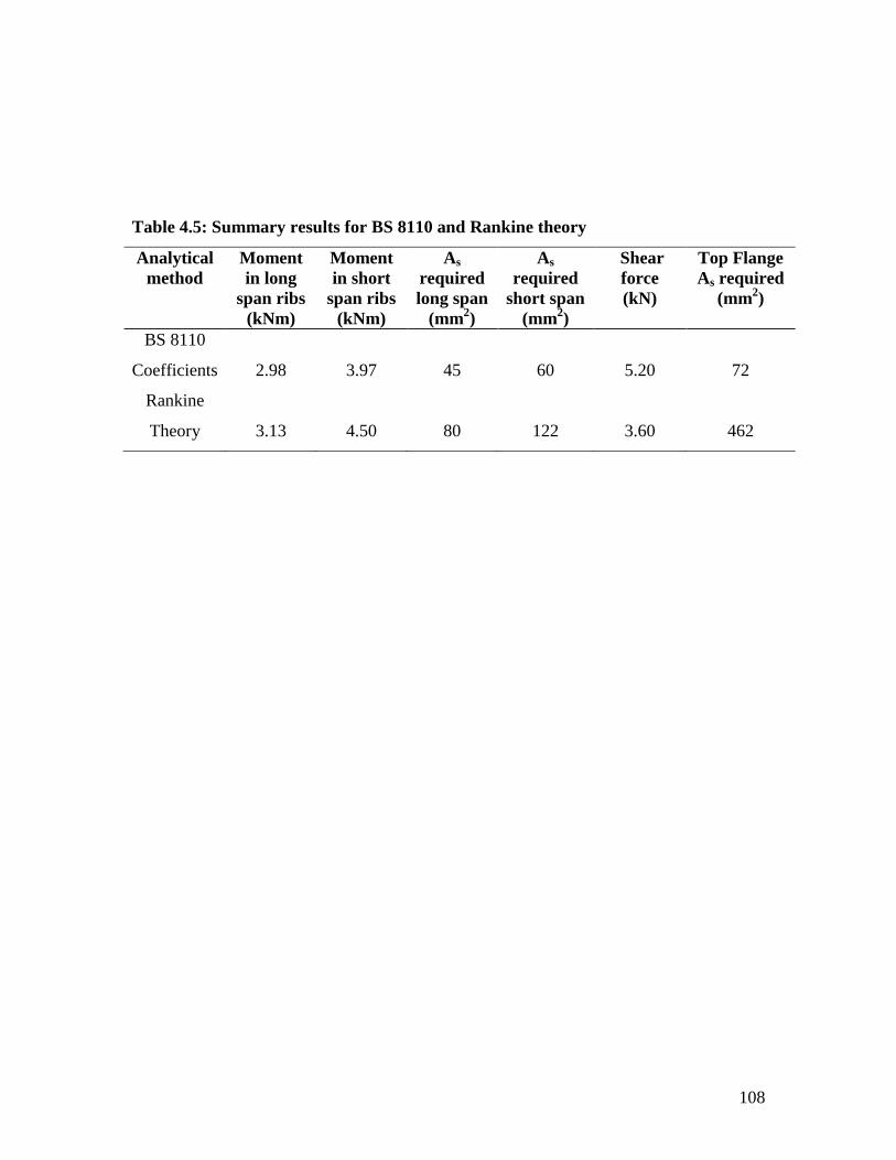
108
Table 4.5: Summary results for BS 8110 and Rankine theory
Analytical
method
Moment
in long
span ribs
(kNm)
Moment
in short
span ribs
(kNm)
As
required
long span
(mm2)
As
required
short span
(mm2)
Shear
force
(kN)
Top Flange
As required
(mm2)
BS 8110
Coefficients
2.98
3.97
45
60
5.20
72
Rankine
Theory
3.13
4.50
80
122
3.60
462
109
Although Mosley et al (1999) provided 2T10 bars in each rib at the bottom (As
=157 mm2) which was adequate to cater for the required steel area and also adequate for
the results from Rankine analysis. But the low analytical results from the use of BS 8110
coefficients may lead to under reinforcements of the ribs and hence allow for service
stress in the steel provided. For the topping or slab portion, the use of 0.12bh gave the
required area of steel to be 72 mm2 which was the minimum required, and a wire mesh
D98 (As=98 mm2) was provided. If this is compared to the yield line analysis results of
462 mm2 with the provision of Y8@100 mm c/c (503 mm
2), then the yield line results
was adequate for the type of eccentric loading that the slabs in the prototypes were
subjected to during loading and transportation to the site.
As discussed in chapter one, the reason for cracks and sometimes outright
failures in the initial waffle slab panels was due to the use of wire mesh that can not
withstand the eccentric load from cranes and transportation to site and eventual
placements of the slabs to their positions on the site. The results obtained for the
minimum reinforcements might be adequate for casting in-situ waffle slabs that were not
exposed to eccentric forces, but not for precast waffle slabs that would be transported
from the factory to the site and subjected to different types of loading conditions.
The reason for the cracks and failure in the precast slab of this research prototype
was because the topping of the slab was subjected to both sagging and hogging moments
during lifting. Since this portion of the slab was not designed to resist tensile moments
(sagging / hogging), the forces generated as a result of lifting produced the tensile force
that caused the slab topping to fail.

110
4.4 Comparison of YLRGT and ETABS
The computer program ETABS (developed by computers and structures Inc.) was also
compared with the Yield line and Rankine Grashoff theory (YLRGT) in order to test the
reliability of the proposed computer program. The result is showed in Table 4.6.
4.4.1 Outcome of W1 and W3
It was observed that the new program gave a higher moment of 2.157 kNm in
the theoretical and 5.526 kNm in the experimental results of waffle W1 while ETABS
results were 1.925 kNm and 4.729 kNm for theory and experiment respectively.
Also the new program gave the results for W3 as 1.653 kNm and 2.880 kNm for theory
and experiment respectively whereas ETABS gave 1.613 kNm and 3.338 kNm for both
theoretical and experimental result respectively for the same panel W3.
Both W1 and W3 were simply supported on the two short sides. The results showed that
ETABS was conservative in the analysis of a simply supported waffle slabs on two short
sides, although the difference in the results of both analysis was about 10% which is still
reliable for any analysis.
4.4.2 Results of W2 and W4
The yield line result for W2 was 0.084 kNm for theory and 1.122 kNm for the
experiment, while ETABS result was 0.502 kNm for theory and 0.581 kNm for
experiment. Also W4 gave 0.066 kNm for theory and 0.590 kNm for experiment in yield
line, whereas ETABS gave the theoretical result to be 0.472 kNm and experimental to be
0.733 kNm. Both slabs were simply supported on all four sides; yield line gave
conservative results in the theory for both slab and the experimental result for W4, while
ETAB gave conservative result in the experimental results of W2.

111
Table 4.6: Comparison of the bending moment of ETABS and YLRGT
ETABS YLRGT
Panels Theoretical
(kNm)
Experimental
(kNm)
Theoretical (kNm) Experimental (kNm)
SP L. Rib S. Rib SP L. Rib S. Rib
W1 1.925 4.729 2.157 0.0074 0.0378 5.526 0.9183 0.0345
W2 0.502 0.581 0.084 0.0031 0.0240 1.122 0.0365 0.2792
W3 1.613 3.338 1.653 0.0112 0.0370 2.880 0.6199 0.0272
W4 0.427 0.733 0.066 0.0200 0.0213 0.590 0.1609 0.1710
W5 0.568 0.851 0.436 0.0023 0.1898 0.947 0.0044 0.0370
W6 0.530 0.686 0.297 0.0102 0.0255 1.276 0.0362 0.0904
SP = Slab portion of waffle
L. Rib = Long rib of waffle
S. Rib = Short rib of waffle
112
4.4.3 Comparison of W5 and W6
The results for W5 were 0.436 kNm theoretical and 0.947 kNm experimental for
yield line, while ETABS was 0.568 kNm theoretical and 0.851 kNm experimental.
Waffle slab W6 gave theoretical result to be 0.297kNm and experimental result of 1.276
kNm for the yield line theory, while ETABS results were 0.530 kNm and 0.686 kNm for
both theoretical and experimental results respectively. The experimental results showed
that ETABS was conservative for both type of waffle slabs, whereas yield line was
conservative in the theoretical results. The differences in all the values obtained varied
and the variation had to do with the support conditions, size of slabs and the magnitude of
load that caused the bending moments in each slab type. Both slabs were supported on
three sides.
4.4.4 General observations of YLRGT and ETABS
Generally, it was observed that both analytical methods showed variation in the
analysis of waffle slabs. The differences in their moments generated were very minimal
and it all depended on the size of the slabs and support conditions. ETABS gave
conservative results in slabs simply supported on two short sides, YLRGT gave
conservative results in slabs supported on four sides, while the results in slabs supported
on three sides varies between the two methods. These observations have showed that
YLRGT method for the analysis of waffle slabs was reliable if compared with existing
methods of analysis. Its advantage over ETABS is the ability to analyse the slab portion
and ribs part of a waffle slab separately as shown in Table 4.6.
In the design of concrete elements, ETABS and other existing programs have a
constant figure of 460 N/mm2 for high yield steel and 250 N/mm
2 for low yield steel as
recommended by BS 8110. Also, in most of these packages, the characteristic strength of

113
concrete had a minimum value of 30 N/mm2 because they were developed to meet the
environmental challenges of specific countries. Most of these programs are not suitable
for the peculiar conditions that are prevalent in Nigeria.
In a research, Salau and Farayola (2006) carried out chemical and mechanical
tests on some samples of locally available steel reinforcing bars in Nigeria, it was
discovered that the chemical contents of all the steel did not conform to international
standards. This non-conformity led to the poor performance of all the locally available
steel bars under the tensile strength test. It was recommended that the characteristics yield
strength of between 280 N/mm2 and 300 N/mm
2 should be adopted during the design
stage. Consequently, YLRGT has introduced some flexibility to all these parameters so
that the designer can use any value desired, which must be within the recommendation of
BS 8110.
This will therefore enhance the acceptability of the proposed method in countries
like Nigeria where most of the steel that are used as reinforcement in a good number of
sites have yield strength that are lower than the BS 8110 recommended values.
Meanwhile, the common concrete characteristic strength that is used in Nigeria is
between 20 N/mm2 and 30 N/mm
2. Hence, this program is friendly to the Nigerian
environment.
4.5 Deflections in Specimens
The deflection of each slab was obtained, the variation in the results of waffle slabs
and the corresponding solid slabs were compared with each other and the graph of load
against deflection was plotted (Figures 4.1 to 4.6).

114
Deflection mm
0.5
12.5
0.0
10.0
7.5
17.5
1.5
15.0
2.5 3.5
5.0
2.5
0.01.0 2.0 3.0
Loa
d
kN
Solid_S1
Waffle_W1
Figure 4.1: Variation in the deflection of W1 and S1

115
Deflection mm
20
8
6
6
4
84
2
0
Lo
ad
k
N
Sol id_slab_S2
Waffle_W2
Figure 4.2: Variation in the deflection of W2 and S2

116
Deflection mm
1
8
0
6
4
12
3
10
5 7
2
02 64
Lo
ad
k
N
Solid_slab_S3
Waffle_W3
Figure 4.3: Variation in the deflection of W3 and S3

117
Deflection mm
1
5
0
4
3
3
6
5
2
1
04 62
Loa
d
kN
Solid_slab_S4
Waffle_W4
Figure 4.4: Variation in the deflection of W4 and S4

118
Deflection mm
2
7
0
6
5
6
8
10
4
3
2
1
80
124
Loa
d
kN
Solid_slab_S5
Waffle_W5
Figure 4.5: Variation in the deflection of W5 and S5

119
Deflection mm
0.5
8
0.0
6
4
12
1.5
10
2.5 3.5
2
01.0 3.02.0
Loa
d
k
N
Solid_slab_S6
Waffle_W6
Figure 4.6: Variation in the deflection of W6 and S6

120
It was observed from Figure 4.1, that solid slab S1 deflected more than waffle slab
W1. The deflection of S1 continued gradually forming a curve until there was a sudden
change in direction at 10 kN. This continued on a straight line until failure at 12 kN. The
waffle W1 curve was gradual; in fact it maintained a parallel deflection below 1mm for a
long time until it got to 12kN where the elastic limit was exceeded. The same condition
applied to S1, when it got to 10 kN, the elastic limit was exceeded. The rate at which slab
S1 deflected showed that its ability to fail rapidly under overload was higher compared
with W1 and it actually failed earlier. This confirmed that it can not withstand as much
load as the corresponding waffle slab. Both slabs were simply supported on two sides.
Figure 4.2, showed the graph of waffle slab W2 and solid slab S2, it was observed that
there was gradual deflection in W2. The curve formed between 1 kN and 7 kN was
gradual until a sudden change at 7 kN which was the elastic limit. S2 also showed a
gradual curve from the beginning until it got to 3 kN where it maintained a straight line to
7 kN which was the failure point. The elastic limit was exceeded at the 3 kN. The amount
of deflection in S2 was greater than that of W2, hence it showed signs of failure earlier
than W2. Both slabs were supported on four sides.
The graph of W3 and S3 (Figure 4.3) showed that S3 failed at 14 kN, and the
amount of deflection in S3 is greater than that of W3. Both graphs showed gradual
deflection from the beginning but as soon as W3 got to 12 kN it collapsed. The elastic
limit for S3 was exceeded at 10 kN. Both slabs were simply supported on two sides.
The graph of W4 and S4 showed some differences when compared with the
previous graphs Figure 4.4. In this case, W4 showed a slightly higher amount of
121
deflection over S4. The curve at W4 was constant until it got to 4 kN where it maintained
a straight line to 6 kN. The elastic limit was exceeded after the 4 kN load point. S4 was
able to maintain its curve to the 2 kN before its changes it directions. Both slabs failed at
the 6 kN, they were supported on four sides.
In the W5 and S5 graph Figure 4.5, the slab S5 showed a gradual rise to 1 kN and
maintain a curve to 2 kN, and change the direction of the curve up to 4 kN. The elastic
limit was exceeded after the 4 kN. The amount of deflection in this slab was higher than
that of its W5 counterpart. The W5 waffle slabs also showed a gradual rise from the
beginning to 2 kN, it then sustained its curve between the 2 kN and 5 kN, after which a
straight line was formed to the 8 kN failure point. The elastic limit was exceeded after the
5 kN load. Both slabs were supported on three sides during the test.
Figure 4.6 showed that, Slab W6 maintained a good curve from the beginning to the
12 kN load point. The amount of deflection in this slab is lower than that of S6. The
shape of S6 showed that it maintained a curve from the beginning to 4 kN and the elastic
limit was exceeded at this point and it eventually failed at 10 kN. Both slabs were
supported on three sides.
All slabs with higher amount of displacements have lower slab stiffness when
compared with those with lower amount of displacements. Waffle W1 had higher slab
stiffness than solid S2; waffle W2 had better stiffness than solid S2, while waffle W3
showed good slab stiffness over solid S3. However, waffle W4 had a lower stiffness
when compared with solid slab S4. Waffle W5 had better slab stiffness than solid S5
while waffle W6 also showed good slab stiffness over solid S6. All the slabs maintained
their stiffnesses within the elastic limit stage, but lost it when ever the elastic limit was

122
exceeded, if the loads were removed before the loss of stiffnesses, there is tendency for
the slab to return to it initial stage, but after losing its stiffnesses, the slab will never
recover it pre-loading stage because the elastic limit was exceeded.
In general, it was observed that all the waffle slab specimens, with the exception of
waffle W4, had better slab stiffness over corresponding solid slab. This must be as a
result of the presence of ribs that was under tension in the various waffle slabs, and also
the slab thickness.
If the corresponding solid slab was to have the same amount of slab stiffness like
the waffle slab, the depth of such solid slab and the reinforcement provided would have
to be increased. This solution was not the best and it was not economical. The nature of
all the curves (both for waffle and solid slabs) had shown that concrete is ductile, and it
can be classified as an elastoplastic material. Such material behave in an elastic manner
until the elastic limit is reached after which they behave plastically (Megson, 2002).
4.6 Mean Deflection in Waffle Slabs and Solid Slabs
Mean deflections in waffle and solid slabs were compared using analysis of variance
(ANOVA) (Miller and Freund, 1987). Mean deflection for waffle slab W1 and solid slab
S1 were significantly different at 5% probability level (Appendix 51). Least significant
difference was used to separate the means (Table 4.7). The results showed that S1 had the
higher mean value of 2.405 mm.
The results of W2 and S2 (Appendix 52) showed that the mean deflection for both slabs
were significantly different at 5% probability level. Least significant difference was also
used to separate the means (Table 4.8). However, S2 had the higher mean of 4.46 mm.

123
Table 4.7: Least significant difference table for S1 and W1
Parameters Deflection Means LSD P 0.05
S1 2.405a 1.885 0.955
W1 0.520b
Means with the same letter under each column are not different at P=0.05.
Means with different letters under each column are different at P=0.05

124
Table 4.8: Least significant difference table for S2 and W2
Parameters Deflection Means LSD P= 0.05
S2 4.46a 2.970 2.520
W2 1.49b
Means with the same letter under each column are not different at P=0.05.
Means with different letters under each column are different at P=0.05

125
The W3 and S3 analysis (Appendix 53) showed that there was no significant
difference in the deflections of both slab at the 5% probability level, since the calculated
variance ratio (F) 3.637 was less than the tabulated (F) 4.96, S3 gave a mean value of
4.15 mm, which was higher than that of W3 (2.04 mm).
In the analysis of W4 and S4 (Appendix 54), the results also showed that there was
no significant difference in the mean deflection for both slabs at the 5% probability level.
The calculated variance ratio (F) 0.591 is less than the tabulated (F) 4.60. W4 had the
higher mean value of 5.68 mm compared to the 4.65 mm of S4.
From Appendix 55, the results also showed that there was no significant difference in
the average mean values of both slab W5 and S5, as the calculated (F) 2.076 is less than
the tabulated (F) 4.75. Solid slab S5 showed a higher mean value of 8.18 mm, compared
with 5.82 mm of W5.
Waffle slab W6 and solid slab S6 also did not reflect any significant difference in their
mean values. This is because the calculated (F) 0.000 is far below the tabulated (F) 4.96.
The mean value of both slab was 1.91 mm, this same mean value contributed to the 0.00
variance ratio obtained (F). (Appendix 56)
Apart from slabs W1, S1, W2 and S2 that showed significant difference in their mean
deflections with standard deviations of +1.131, +0.388, +3.080, +1.025 respectively , all
other slab samples showed that there was no significant difference in their mean value at
p<0.05 level. It can be generally concluded that despite the ability of solid slabs to fail
earlier than waffle slabs, due to its low stiffness which resulted in higher deflection value,
it can still maintain its stiffness up to p<0.05 level with its corresponding waffle slabs in

126
the case of solid slabs S1 and S2. The remaining results showed that there was minimal
difference between the mean deflection of solid and waffle slabs.
4.7 Correlation between the Deflections in Slabs of Similar Support Condition
The Pearson‟s correlation analysis method was used to determine the correlation
of the deflections of slabs that are subjected to the same boundary conditions but of
different sizes. From Appendix 57, the result of the analysis shows that the correlation
coefficient in the deflection of both slab W1 and W3 is 0.984 and it is significant at 0.01
levels.
For slabs W2 and W4, the correlation coefficient is 0.988, and it is significant at 0.01
levels. See Appendix 58. Waffle slabs W5 and W6 showed a correlation coefficient of
0.919 and it is also significant at 0.01 levels (Appendix 59). The results for S1 and S3
also gave a correlation coefficient of 0.983, and it is significant at 0.01 levels as well. See
Appendix 60. S2 and S4 gave a coefficient of 0.997 and were significant at the 0.01
levels (Appendix 61). From Appendix 62, solid slabs S5 and S6 gave a coefficient of
0.974 values, and it is also significant at 0.01 levels.
It can be generally concluded that the results obtained in the comparison showed
that the deflections were within the same range, indicating a good relationship between
the displacements values and positive correlation results. All results were significant at
the 0.01 levels. This can imply that slabs of the same boundary conditions have
corresponding displacement, not withstanding the sizes of the slabs.

127
4.8 Flexural Cracking
Members subjected to bending generally exhibit a series of distributed flexural
cracks, even at service load. These cracks are harmless and can not cause any damage to
the structure unless the widths become excessive (Mosley et al, 1999). Excessively wide
cracks can be unsightly and spoil the appearance of an exposed concrete surface. They
can allow the ingress of moisture and accelerate corrosion of the reinforcement and
durability failure. In exceptional cases; they can reduce the contribution of the concrete to
the shear strength of a member (Gilbert, 2001).
The crack width at service for both the waffle and solid slabs were estimated,
Table 4.9, the example in Appendix 63 is the estimated crack width for solid slab S1 at
service. The results showed that all the solid slabs have lower crack widths at service,
when compared with corresponding waffle slabs. This is because the estimated crack
width in waffle at service was based on the slab portions only, the ribs were not
considered. The depth of the slab portion was small if compared with that of the solid
slab, also the size of reinforcement used (wire mesh) in the slab portion was small if
compared to the steel reinforcement used in the solid slabs and these were the parameters
used to determine the estimated crack width. In the experiment, the crack widths at
failure in waffle slabs were smaller than those of solid slabs. The presence of ribs in the
waffle reduced the effect of load on the slab portion, since the ribs were directly exposed
to tensile forces instead of the slab portion. The solid slabs were however exposed to the
direct tensile forces which resulted in the flexural cracks that were formed.

128
Table 4.9: Crack width at failure and service
Specimens Crack width at
failure load (mm)
Estimated crack width
at service (mm)
W1 0.60 0.425
W2 0.35 0.065
W3 0.34 0.232
W4 0.25 0.063
W5 0.35 0.054
W6 0.62 0.283
S1 1.20 0.035
S2 0.75 0.002
S3 0.90 0.049
S4 0.70 0.003
S5 1.10 0.006
S6 1.30 0.009

129
4.8.1 Comparison of mean crack width between waffle slab and solid slab
Crack width mean at failure load in waffle and solid slabs were compared using
analysis of variance. The crack width mean for waffle slab and solid slab were
significantly different at 5% probability level (Appendix 64). Least significant difference
was used to separate the means, and the results showed that the differences in means were
very minimal (Table 4.10). The results showed that solid slab had the higher mean value
of 0.99 mm, compared to that of waffle slab which is 0.48 mm. These results confirmed
that the crack widths formed in solid slabs were wider than those of waffle slabs in the
experiment.
Consequently, the presence of excess crack width in solid slabs samples must have
contributed to their earlier failure when compared with corresponding waffle slabs.
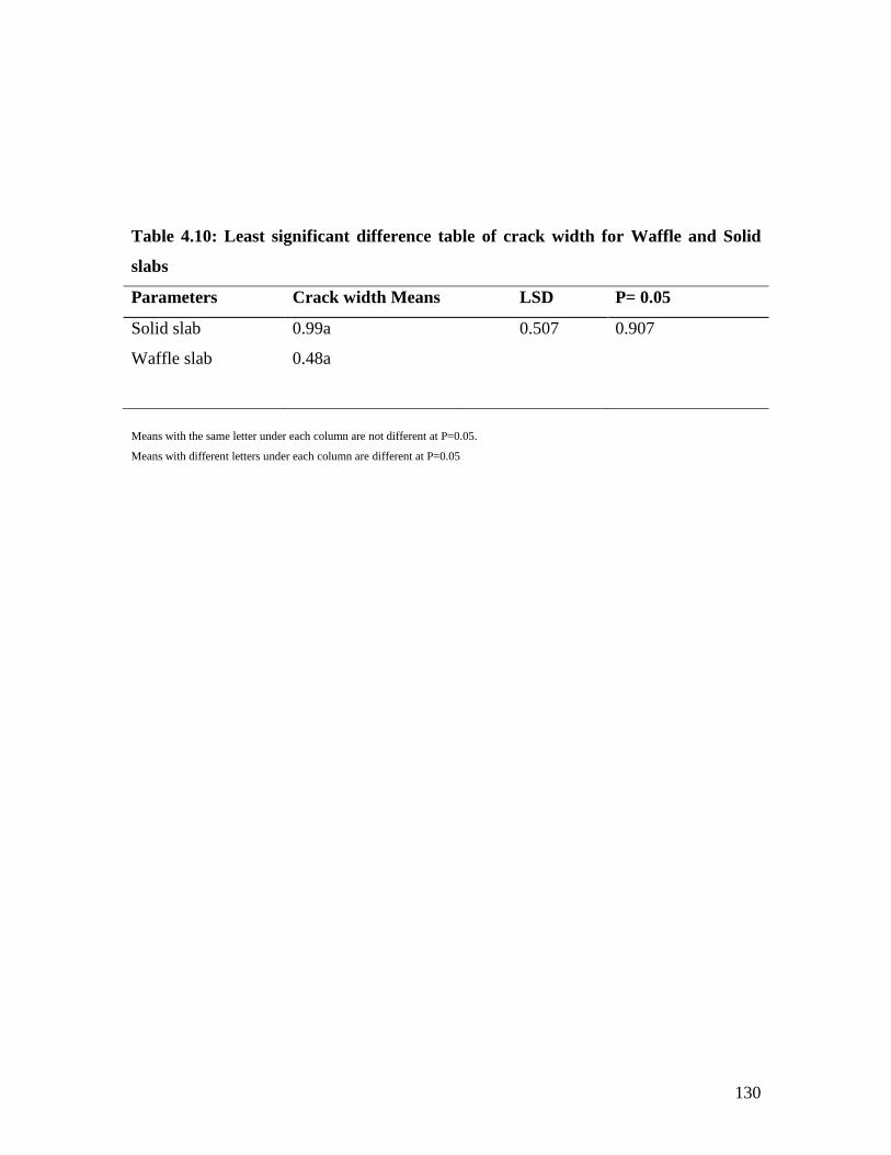
130
Table 4.10: Least significant difference table of crack width for Waffle and Solid
slabs
Parameters Crack width Means LSD P= 0.05
Solid slab 0.99a 0.507 0.907
Waffle slab 0.48a
Means with the same letter under each column are not different at P=0.05.
Means with different letters under each column are different at P=0.05

131
CHAPTER FIVE
CONCLUSIONS AND RECOMMENDATIONS
5.1 Conclusions
The structural characteristics of waffle slabs have been determined through the
investigation of the slabs and its response to applied loads. The bending moments of the
slabs were determined using YLRGT.
i. The response of waffle slabs to load afforded their advantages over solid slabs
because the crack width formed as a result of loading to failure is generally small
when compared to corresponding solid slabs. The crack patterns formed in solid slabs
follow the effects of the types of support conditions which the slabs were exposed to,
unlike waffle slabs where the crack patterns were not precise and did not follow a
particular pattern. This was due to the presence of ribs in the waffle slabs.
ii. The bending moments of waffle slabs are generally higher than that of solid slabs in
all the tests carried out except in two cases where the collapse load of both slabs were
equal. This implied that the stiffness of waffle slab is higher than that of solid slabs in its
response to failure loads.
iii. The grillage analytical method that was used in the analysis of the ribs in the
prototype was defective because it considered moments in the longitudinal ribs only
while neglecting the transverse ribs, although nominal reinforcements were provided for
the transverse ribs, this eventually led to over reinforcement of the ribs. The Rankine
Grashoff method adopted in the analysis of the model was able to overcome this
defect in the prototype by providing appropriate reinforcement for both transverse
and longitudinal ribs.

132
iv. Statistical analysis revealed that solid slabs generally have higher mean deflections
than waffle slabs. However, solid slab S1 and S2 are significantly different in mean
deflections at (p=0.05) over the corresponding waffle slabs W1 and W2 respectively. The
significant difference between the other solid slabs and corresponding waffle slabs are
less than 1%. This implied that solid slabs deflect more than waffle slabs under failure
loads.
v. The graph of load against deflection also showed the gradual deflection of both waffle
and solid slabs, but solid slabs generally deflect more than waffle slabs.
vi. The Pearson‟s correlation analysis method revealed that slabs that are subjected to the
same boundary conditions showed positive correlation results in their deflections and are
all significant at 0.01 levels.
vii. The crack width formed in solid slab is significantly different from that of waffle
slabs at the (p=0.05) probability level, although the difference is very minimal. This
implied that the average crack width in solid slab is wider than that of waffle
slab at failure load. This must have contributed to the low flexural strength of solid slabs
if compared with waffle slabs.
viii. YLRGT also gave more dependable results when it was compared with the BS 8110
slab coefficients method that some engineers have adopted in the analysis of the waffle
slab ribs.
ix. The study has showed that the reason for the failures observed in the prototype was
as a result of approximate analytical procedures adopted in the design of the waffle slabs
and the provision of inadequate reinforcements at the slab portions while the ribs were
over reinforced.

133
x. YLRGT developed in this study for solving the problem was validated in the case
study; by comparing the results of YLRGT analytical method with the results obtained
from ETABS which is based on the finite element method (FEM). The results obtained
showed good relationship between the two methods. However, the advantage of YLRGT
over ETABS is the analysis of the slab portion separately using the Yield line theory and
the rib portion by adopting the Rankine Grashoff theory in waffle slabs, the program can
also be effectively used for the analysis of solid slabs.
xi. The introduction of YLRGT has facilitated the improved analysis of pre-cast waffle
slabs. The use of YLRGT will enhance the structural integrity of pre-cast waffle slab as
revealed when compared with the finite element method. The program is safe and it is
very easy to use.
5.2 Contribution to Knowledge
i. This research has provided an improved method of analysing and designing separately,
the slab and rib of waffle slabs. Adequate reinforcements can therefore be put in the
appropriate sections to ensure structural integrity and reliability.
ii. The new method of analysis (YLRGT) can also be used in solving the problems of
solid slabs.
5.4 Recommendations for Further Research
The following suggestions are recommended for further research as extension of this
investigation:
(i.) Equipment that can give incremental results for every crack width measured is
recommended.

134
(ii) The use of crack measuring meter or crack detecting microscope instead of Vernier
caliper is suggested to give correct values of all measured crack widths.
(iii). During the conception and design of civil engineering structures, efforts should be
made by the design engineer to adopt effective and reliable analytical methods in order to
avoid the type of problems encountered in this study.

135
REFERENCES
Aalami, B.O.and Kelly, G.S. (2001). Design of Concrete Floors with Particular reference
to Post- Tensioning, PTI technical notes, Issue 11. 1717 West Northern Avenue,
Suite 114, Phoenix Arizona 85021.
Aalami, B.O. (2005). Structural modelling and analysis of concrete floor slabs.
Concrete international, December edition.
Abdel-Karim, R. and Mahmood , I.M.A. (2006). The effect of beams stiffnesses on the
load distribution in a single simply supported two-way ribbed slab, The Islamic
University Journal (series of natural studies and engineering), Vol. 14, No.1, pp
191-208.
Abdul-Wahab, H.M.S. and Khalil, M.H. (2000). Rigidity and strength of orthotropic
reinforced concrete waffle slabs, Journal of Structural Engr.Vol.126, Issue 2,
Pp 219-227.
Adapt Technical Note. (2006). Structural concrete soft ware system, Waffle slab design.
www.adaptsoft.com. 1733 Woodside road, Suite 220, Redwood City,
California, USA.
Akinyele, J.O. and Alade G.A. (2011).The use of effective methods in the analysis of
civil engineering structures. Book of Abstracts, Science Engineering and
Technology (SET) Conference, 2011. Osun State University,
Oshogbo, Nigeria.
Akinyele, J.O. (2011). Comparison of computer based Yield line theory with
Elastic theory and Finite element methods for solid slabs.
Intrenational Journal of Engineering and Technology. Vol.3 (1), 2011. pp1-5.
Bakht, B. and Jaegar, L.G. (1985). Bridge Analysis Simplified, McGraw Hill Book
Company, New York, pp 24-27.
Bankole, I.O. (2007). Modeling the structural behaviour of non-prismatic slab bridge.
A Ph.D Thesis, submitted to the Department of Civil Engineering, University of
Ibadan, Ibadan Nigeria.
Beckett, D. (1973). An Introduction to structural design. Vol.1, Surrey University press.
Pp26-33.

136
Bellis, M. (2009). The history of concrete and cement. Retrieved January 20, 2009 from
www.About.com.
British Standard Institution.(1971).Method of making and curing test
specimens.BS1881: part 3. London.
British Standard Institution. (1971).Method of testing for strength.BS1881: part 4.
London.
British Standard Institution. (1983). Method of normal curing of test
specimens.BS1881:part111. London.
British Standard Institution. (1997). Structural Use of Concrete, BS 8110: Part 1.
London.
Buildings. (2005). An Engineers guide to: Economical Concrete Floor Systems (IS063).
Portland cement Association, Skokie IL, www.cement.org
Retrieved March 2005.
Buyukozturk, O. (2004). Mechanics and Design of concrete structures. Massachusetts
Institute of Technology.
Carper, K.L. (1998). Current structural safety topics in North America. The Structural
Engineer, Vol. 76, No. 12. pp 233-237.
Chee, K.N. Timothy, J.E. and Daniel, K.T.L.(2008). Theoretical evaluation on effects of
opening on ultimate load carrying capacity of square slabs. Electronic Journal of
Structural Engineering, Volume 8. http://www.ejse.org. Retrieved May 2008
Childs, D. (2008). Tutorials on the Grillage analysis of bridge decks.
http://www.childs-ceng.demon.co.uk. Retrieved May 2008
Daniel, A.S. and Onur, G. (2005). The design of William J.Clinton Presidential Centre.
The civil Engineering Magazine, March edition.
Dunham, C.W. (1964). Advanced reinforced concrete, Mc-Graw-Hill book
Company, New York.
El-Sebaskly, I.S. (1979). Behaviour of Reinforced and Pre-strengthed Waffle Slabs.
Thesis. University of Windsor, Windsor, Ontario, Canada.
ETABS User guide. (2005). Integrated Building Design Software.
Computers and Structures Inc. 1995, University Avenue, Berkeley, California.
94704. USA

137
Ferguson, P.M. (1965). Reinforced Concrete Fundamentals with emphasis on ultimate
strength, 2nd
edition. John Wiley & Sons Ltd New York Pp 319.
Geng, H, Chang, N.Y, and Wang, T. (2006). Definition of yield zone on concrete barrier
structure under a transverse impact load. Proceedings of ASCE 9th
International
Conference. Pp 190-195.
Gilbert, R.I. (2001). Shrinkage, Cracking and Deflection-the Serviceability of Concrete
Structures. Electronic Journal of Structural Engineering, Volume 1.
http://www.ejse.org.
Gilbert, R.I. and Guo, X.H. (2005). Time-Dependent deflection and deformation of
reinforced concrete flat slabs. An experimental study. ACI Structural Journal,
May/June edition.
Gohnert,M.(2006). Postulate on shear in reinforced concrete. Journal of the South
African Institution of Civil Engineering. Vol. 48, No 4, Paper 609, Pp 9-13
Gordon, S.R. and May, I. M. (2004). Observations on the grillage analysis of slabs.
The structural Engineers’ Journal, Vol.82, No. 3, pp 35-38.
Gudmand-Høyer, T. (2003). Yield line theory for concrete slabs subjected to axial force.
Thesis. Department of Structural Engineering and Materials, Technical
University of Denmark.
Howard, C.Q. and Hansen, C.H. (2002). Vibration analysis of waffle floors. Unpublished
Department of Mechanical Engineering, University of Adelaide, South Australia.
Jaeger, L.G. and Bakht, B. (1982). The grillage analogy in bridge analysis. Canadian
Journal of Civil Engineering, Vol. 9, part 2, pp 224-235.
Jamal, A.(1998). Studies on the effects of Shear Reinforcement in Rib-stiffened
Reinforced Concrete Slabs. Thesis. University of Windsor, Ontario,
Canada.
Johansen, K.W. (1963). Yield-line theory. Portland Cement Institute
Kenichi,I and Ai.S.(2005). Collapse mechanism of the Windsor building by fire in
Madrid and the plan for its demolition process. International Workshop on
Emergency and Rescue. October31- November1.

138
Kennedy, G and Goodchild, C.H, (2004). Practical yield line design. The concrete centre,
Riverside house, 4 Meadows Business Park, station approach, Camberly, Surrey.
Kharagpur, I.I.T.(2009). Yield line analysis for slabs, Reinforced concrete design,
module12, version 2, www.freeebook.com Retrieved January 2009.
Ki-Sung, K. Ki-Sup,H. and Sang-Chol, L. (2001).Plastic analysis of simply-supported
grillage under a point load. International Journal of Offshore and Polar
Engineering,Vol. 11, No. 4.
Konda, T.F. (2003). Construction and Evaluation of the first Modified Beam-in Slab
Bridge. A paper presented to Department of Civil and Construction
Engineering, Iowa State University
Kong, F.K and Evans, R.H. (1987).Reinforced and Prestressed Concrete.
Chapman and Hall, 2-6 Boundary Row, London SE1 8HN. Pp 304-305.
Krishna Raju, N.(1988). Advanced reinforced concrete design. CBS Publishers, 485, Jain
Bhawan, Shahadra, Delhi.
Lee, K.S. Song, J.Y. Su-kim, K. Kim, S.C. & Kim, J.H.(2006). Application of the refined
mesh method for the strength estimation around openings. Key Engineering
Materials,Vol. 321-323, Pp 16-19.
Lim, C.S.L. (2003). Membrane action in fire exposed concrete floor system,
Ph.D Thesis, Department of Civil Engineering, University of Canterbury,
Christchurch, New Zealand.
Macgregor, J.G. (1997). Reinforced concrete Mechanism and design. 3rd
edition, Prentice
and Hall, Upper Saddle River, New Jersey.
Maher, K. (2007). Bending moment distribution at the main structural elements of skew
deck- slab and their implementation on cost effectiveness, American Journal of
Applied Science 4(12): 1036-1039.
Megson, T.H.G. (2002).Structural and Strength analysis, Butterworth – Heinemann,
Linacre house, Jordan Hill, Oxford Ox 28 DP. Pp182.
Miller, I. and Freund, J.E. (1987). Probability and statistics for engineers, 3rd edition
Prentice-Hall of India, New Delhi.
Mindes, S and Young, J.F. (1981). Concrete, Prentice-Hall, Inc.
Englewood Cliffs, N.J 07632 . Pp 473.
139
Mosalam, K.M. and Naito, C.J. (2002). Seismic evaluation of gravity-load-designed
column-grid system, Journal of Structural Engineering, Vol.128, No.2.
Mosley, W.H. and Bungey, J.H.(1990).Reinforced concrete design, 4th
edition,
Macmillan Education Limited, Houndmills, Basingstoke, Hampshire. Pp209.
Mosley, W.H., Bungey, J.H. and Hulse. R.(1999). Reinforced concrete design, 5th
edition,
Macmillan Education Limited, Houndmills, Basingstoke, Hampshire RG21 6XS.
Pp207.
Murray, N.W. (1986). Introduction to the theory of thin walled structure, The Oxford
Engineering Science Series 13, Clarendon press, Oxford.
Neville, A.M. (1990). Concrete Technology, Longman Group UK Ltd, Longman House,
Burnt Mill Harlow. Essex CM 20.2JE, England. Pp 209.
Nilson, A.H., and Winter, G. (1991).Design of concrete structures. Eleventh Edition.
McGraw-Hill Book Company. New York.
Nilson, A.H.(1997). Design of concrete structures. Twelfth Edition. McGraw-Hill Book
Company. New York.
Oyenuga,V.O.(2001). Simplified reinforced concrete design, Astros Ltd, Surulere, Lagos,
Nigeria.
Park, R . and Gamble, W.L. (2000). Reinforced Concrete Slabs – Second Edition, John Wiley &
Sons,Inc., NY, 551-620.
Punmia, B.C., Ashok, K.J. and Arun, K.J. (2006). Reinforced Concrete Structures,
10th Edition, Laxim Publications Ltd, New-Delhi.
Prasad, J. Chander, S. and Ahuja, A.K. (2005). Optimum dimensions of waffle slabs for
medium size floors. Asian journal of civil engineering (Building and Housing)
Vol.6, No.3 Pp 183-197.
Quaqish, M.S.(2005).Effect of Skew Angle on Distribution of Bending Moments in
Bridge Slabs, Journal of Applied Sciences.
Rahman, M.K. Pillai, S.K.G and Baluch, M.H. (2010). Strut-and- tie model for waffle
slabs. Advanced and trends in Structural Engineering, Mechanics and
Computation. The proceeding of the 4th
International conference on Structural
Engineering Mechanics and Computations, (SEMC 2010), Taylor and Francis
Group, London. Pp 193.

140
Rajagopalan, N. (2005).Prestressed Concrete, 2nd
Edition. Narosa Publishing
House PVT. Ltd. 22 Delhi Medical Association Road, Daryaganji, New Delhi.
Rajput, R.K. (1998). A text book of fluid Mechanics and Hydraulic Machines.
Chand & Company Ltd Delhi India. Pp421.
Ramsay, A.C.A. and Johnson, D.(1997). Geometric optimization of yield-line patterns
using a direct search method. Journal of Structural optimization, Vol.14
Pp 108- 115.
Sadusky, K.M. (2004). Pro-con Structural study of alternative floor system. Technical
Assignment Journal No 2.
Salau, M.A. and Farayola, A.F.(2006). Structural engineering characteristics of locally
available steel reinforcing bars in Nigeria. NSE Technical Transactions. Vol. 41,
No.4 Pp 34-50. October – November, National Engineering Centre,
No.1 Engineering Close, Victoria Island, Lagos, Nigeria.
Sivagamasundari, R and Kumara, G. (2008). A comparative study on the flexural
behaviour of one-way concrete slabs reinforced with GFRP reinforcements and
conventional reinforcements when subjected to monotonic and repeated loading.
The open Civil Engineering Journal, Vol. 2. pp24-34.
Tan, G.H. Brameld, G.H. and Thambiratman, D.P. (1998). Development of an analytical
model for treating bridge-vehicle intersection. Engineering Structures, Vol. 20,
Nos 1-2, pp 54-61.
The Concrete Centre, (2006). Waffle slabs. http://www.concretecentre.com
Retrieved ( May 2006).
Thompson, F. and Haywood, G.G. (1986). Structural analysis using virtual work,
Chapman and Hall Ltd. 11 New Fetter Lane, London EC4P 4EE.. pp253.
Tiedman, J. Albrecht, P. and Cayes, L. (1993). Behaviour of two-span continuous bridge
under axle loading. Journal of Structural Engineering 119 (4): 1234-1250.
Vinson, J.R. (1989). The behaviour of thin walled structures: Beams, Plates and Shells.
Mechanics of surface structures, Kluwer Academic Publishers, Dordrecht, The
Netherland.

141
Waffle-Crete International.( 2009). The multiple use of waffle-crete.
www.waffle-crete.com. Accessed, March, 2009.
Wang, T. Lu, M. Wang, L. (2003). Strength-strain relation for concrete under triaxial
loading. ASCE Engineering Mechanics Conference, July 16-18.University
of Washington, Seattle.
West, R. (1973).Recommendations on the use of grillage analysis for slab and pseudo-
slab bridge decks, Cement and Concrete Association and Construction Industry
Research and Information Association, London, UK.
Zeng, H. Kuen, J. Sun, J. & Stalford, H. (2007). An Analysis of Skewed Bridge/Vehicle
Intersection Using the Grillage Method. Centre for Structural Control,
University of Oklahoma, Norman, OK 73072.

142
APPENDICES

143
Appendix 1: Theoretical result of waffle slab W1.
ANALYSIS OF WAFFLE SLABS USING YIELD LINE THEORY
CODE B.S.8110 PART1 1997
Designed by Akinyele J.O
simply supported on two sides
Slab Long span (ly) (m) 1.353
Slab Short span (lx) (m) 0.43
Depth of Slab part (mm) 27
Distance between ribs on Long Span (m) 0.26
Distance between ribs on Short Span (m) 0.135
Rib width (mm) 20
Depth of ribs (mm) 33
Total depth of slab (mm) 60
Cover to reinforcement (mm) 5
Effective depth of slab (mm) 22
Slab dead load (kN/m2) 0.9072
Slab imposed load (kN/m2) 3.2
Finishes and Partitions 5.32
Total load on slab (kN/m2) 9.4272
I1 fixity at 1st support 0
I2 fixity at 2nd support 0
Bending moment in Slab (KNm) 2.15719
DESIGN OF SLAB
Concrete characteristic strength (N/mm2) 20
Steel characteristic strength (N/mm2) 250
Maximum Lever arm factor 0.95
Maximum K- value 0.156
Moment M 2157190
K-value 0.22285
Lever arm Factor 0.54887
Used Lever arm 0.54887
Area of Steel (mm2) 752.192
Provide B785 structural mesh@100mmc/c bottom (785mm
2)
ANALYSIS AND DESIGN OF RIBS
Adopting the Rankine Grashoff Theory.
Number of Ribs on Long Span (ly) 4
Number of Ribs on Short Span (lx) 2
Weight of Slabs (kN/m2) 9.4272
Total Load on Slab (KN) 5.48465
Weight of Ribs (kN/m) 0.01584
Total weight of Ribs on long span (ly), (kN) 0.10715
Total weight of Ribs on Short span (lx), (kN) 0.01362
Total weight of Finishes (kN) 0.58179
Total Live Load (kN) 0.93086
Total Load on grid floor (kN) 7.11808
q=Load per Area (m2) 12.2348
Denominator for qx and qy 3.38531
Load sheared on short span (qx), (KN/m2) 12.1112
Load sheared on Long span (qy), (kN/m2) 0.12355

144
Moment on short span Mx (kN.m) 0.03778
Moment on long span My (kN.m) 0.00735
Shear force on short span, Vx, (kN) 0.67701
Shear force on long span, Vy, (kN) 0.01128
DESIGN
Steel characteristic strength (N/mm2) 250
Short span design moment (Nmm) 37789.3
Cover to ribs (mm) 5
Effective depth of ribs 28
K.value 0.12050
Lever arm Factor 0.84074
Used Lever arm 0.84074
Area of Steel (mm2) 3.32020
Provide 1R6@Bottom-28mm2
Long span design moment (Nmm) 7351.06
K.value 0.02344
Lever arm Factor 0.97323
Used Lever arm 0.97323
Area of Steel (mm2) 1.13582
Provide 1R6@Bottom-28mm2
END DESIGN

145
Appendix 2: Theoretical results of waffle slab W2.
ANALYSIS AND DESIGN OF WAFFLE SLABS USING THE YIELD LINE THEORY.
CODE B.S. 8110: PART 1: 1997.
Designed By : Engr. Akinyele J.O
Simply supported on all four sides.
Slab Length(Long span) (ly) (m) 0.9
Slab Width (Short span) (lx) (m) 0.3
Rib width (mm) 20
Distance between ribs on Long span (m) 0.2
Distance between ribs on Short span (m) 0.17
Depth of slab portion (mm) 15
Depth of ribs (mm) 35
Total depth of slab (mm) 50
Effective depth of slab (mm) 10
Slab dead load kN/m2
0.504
Imposed load on slab kN/m2
5.32
Finishes and Partition load 3.2
Total load on slab (kN/m2) 9.024
ANALYSIS OF SLABS.
Fixity ratio for continuous supports on any side
Fixity ratio short span left side I1 0
Fixity ratio long span bottom I2 0
Fixity ratio short span right side I3 0
Fixity ratio long span top I4 0
Reduced sides ar' 0.3
Reduced sides br' 0.9
Bending moments in slab (KNm) 0.08434
DESIGN
Cover to reinforcement. (mm) 5
Concrete characteristic stress (N/mm2) 30
Steel Characteristic Stress (N/mm2) 250
Maximum lever arm factor 0.95
Maximum K- Value 0.156
Moment M 84339.69
K- value 0.028113
Lever arm factor 0.967721
Used Lever arm 0.95
Area of steel (mm2) 37.38047
Provide R2.5@100mmc/c(49mm2)
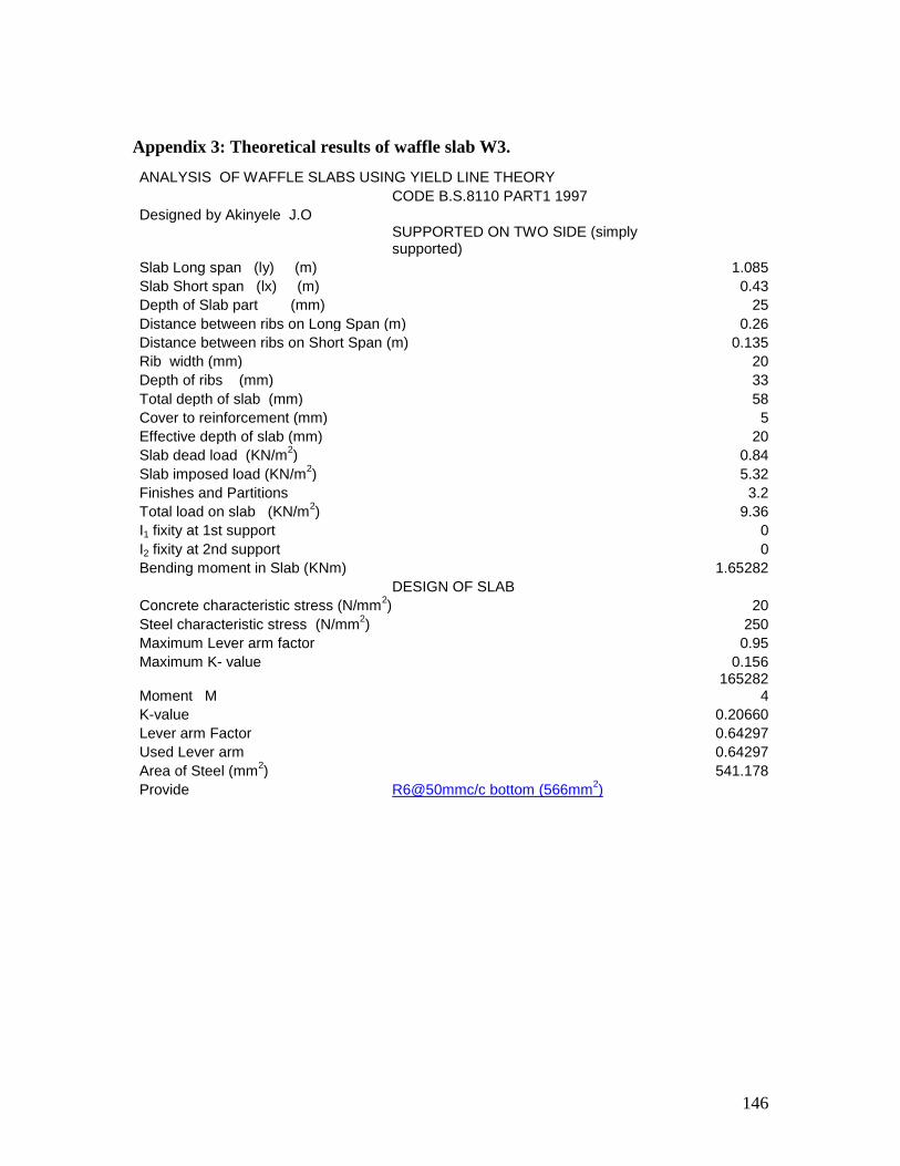
146
Appendix 3: Theoretical results of waffle slab W3.
ANALYSIS OF WAFFLE SLABS USING YIELD LINE THEORY
CODE B.S.8110 PART1 1997
Designed by Akinyele J.O
SUPPORTED ON TWO SIDE (simply supported)
Slab Long span (ly) (m) 1.085
Slab Short span (lx) (m) 0.43
Depth of Slab part (mm) 25
Distance between ribs on Long Span (m) 0.26
Distance between ribs on Short Span (m) 0.135
Rib width (mm) 20
Depth of ribs (mm) 33
Total depth of slab (mm) 58
Cover to reinforcement (mm) 5
Effective depth of slab (mm) 20
Slab dead load (KN/m2) 0.84
Slab imposed load (KN/m2) 5.32
Finishes and Partitions 3.2
Total load on slab (KN/m2) 9.36
I1 fixity at 1st support 0
I2 fixity at 2nd support 0
Bending moment in Slab (KNm) 1.65282
DESIGN OF SLAB
Concrete characteristic stress (N/mm2) 20
Steel characteristic stress (N/mm2) 250
Maximum Lever arm factor 0.95
Maximum K- value 0.156
Moment M 165282
4
K-value 0.20660
Lever arm Factor 0.64297
Used Lever arm 0.64297
Area of Steel (mm2) 541.178
Provide R6@50mmc/c bottom (566mm2)

147
Appendix 4: Theoretical results of waffle slab W4.
ANALYSIS AND DESIGNED OF WAFFLE SLABS USING THE YIELD LINE THEORY.
CODE B.S. 8110: PART 1: 1997.
Designed By : Engr. Akinyele J.O
Simple supported on all four sides.
Slab Length(Long span) (ly) (m) 0.407
Slab Width (Short span) (lx) (m) 0.364
Rib width (mm) 20
Distance between ribs on Long span (m) 0.2
Distance between ribs on Short span (m) 0.17
Depth of slab portion (mm) 15
Depth of ribs (mm) 35
Total depth of slab (mm) 50
Effective depth of slab (mm) 10
Slab dead load kN/m2
0.504
Imposed load on slab kN/m2
5.32
Finishes and Partition load 3.2
Total load on slab (kN/m2) 9.024
ANALYSIS OF SLABS.
Fixity ratio for continuous supports on any side
Fixity ratio short span left side I1 0
Fixity ratio long span bottom I2 0
Fixity ratio short span right side I3 0
Fixity ratio long span top i4 0
Reduced sides ar' 0.364
Reduced sides br' 0.407
Bending moments in slab (KNm) 0.066567
DESIGN
Cover to reinforcement. (mm) 5
Concrete characteristic stress (N/mm2) 20
Steel Characteristic Stress (N/mm2) 250
Maximum lever arm factor 0.95
Maximum K- Value 0.156
Moment M 66567.44
K- value 0.033284
Lever arm factor 0.961539
Used Lever arm 0.95
Area of steel (mm2) 29.50357
Provide R2.5@100mmc/c(49mm2)

148
Appendix 5: Theoretical results of waffle slab W5.
ANALYSIS AND DESIGNED OF WAFFLE SLABS USING THE YIELD LINE THEORY CODE: B.S. 8110: Part 1 1997 Designed By : Akinyele J.O
Simply supported on 3 sides
Slab Long Span (ly) (m) 1.312
Slab Short Span (lx) (m) 0.3
Depth of Slab part (mm) 25
Distance between ribs on long span (m) 0.32
Distance between ribs on short span (m) 0.14
Rib width (mm) 20
Rib depth (mm) 33
Total depth of slab (mm) 58 Cover to reinforcement (mm) 5 Effective depth of slab (mm) 20
Slab dead load (kN/m2) 0.84
Slab imposed load (kN/m2) 5.32
Finishes and Partition load 3.2 Total load on Slab (kN/m
2) 9.36
For case A, = h1+h3 <b
I1= fixity1 for left side of short span 0
I2= fixity2 for supported side of long span 0
I3= fixity3 for right side of short span 0
Reduced span br (m) 1.312
K'= redistribution factor 0.152439
h= factor to determine yield length 0.236725
1st Bending moment in slab (kNm) 0.436058
For case B, = h1+h3 =b
b' = dimensions 0.6
2nd.Bending moment in slab (kNm) 0.303302
DESIGN
Concrete characteristic stress (N/mm2) 20
Steel Characteristic Stress (N/mm2) 250
Maximum Lever arm factor 0.95
Maximum K- value 0.156 Used Bending moment (KNm) 0.436058
Moment M 436058.3
K-value 0.054507
Lever arm factor 0.935243
Used Lever arm 0.935243
Area of Steel (mm2) 98.15818
Provide [email protected]/c bottom(196mm
2)

149
Appendix 6: Theoretical result of waffle slab W6.
ANALYSIS AND DESIGNED OF WAFFLE SLABS USING THE YIELD LINE THEORY CODE: B.S. 8110: Part 1 1997 Designed By : Akinyele J.O
Simply supported on 3 sides
Slab Long Span (ly) (m) 0.86
Slab Short Span (lx) (m) 0.36
Depth of Slab part (mm) 15
Distance between ribs on long span (m) 0.32
Distance between ribs on short span (m) 0.14
Rib width (mm) 20
Rib depth (mm) 35
Total depth of slab (mm) 50 Cover to reinforcement (mm) 5 Effective depth of slab (mm) 10
Slab dead load (kN/m2) 0.504
Slab imposed load (kN/m2) 5.32
Finishes and Partition load 3.2 Total load on Slab (kN/m
2) 9.024
For case A, = h1+h3 <b
I1= fixity1 for left side of short span 0
I2= fixity2 for supported side of long span 0
I3= fixity3 for right side of short span 0
Reduced span br (m) 0.86
K'= redistribution factor 0.27907
H= factor to determine yield length 0.255007
1st Bending moment in slab (kNm) 0.296852
For case B, = h1+h3 =b
b' = dimensions 0.72
2nd.Bending moment in slab (kNm) 0.276466
DESIGN
Concrete characteristic stress (N/mm2) 20
Steel Characteristic Stress (N/mm2) 250
Maximum Lever arm factor 0.95
Maximum K- value 0.156 Used Bending moment (KNm) 0.296852
Moment M 296852.4
K-value 0.148426
Lever arm factor 0.791688
Used Lever arm 0.791688
Area of Steel (mm2) 157.8784
Provide R5/B196Struct.mesh100mmc/c

150
bottom(196mm2)
Appendix 7: Theoretical result of solid slab S1.
ANALYSIS OF WAFFLE SLABS USING YIELD LINE THEORY
CODE B.S.8110 PART1 1997
Designed by Akinyele J.O
simply supported on two short sides
Slab Long span (ly) (m) 1.353
Slab Short span (lx) (m) 0.43
Depth of Slab part (mm) 40
Distance between ribs on Long Span (m) 0
Distance between ribs on Short Span (m) 0
Rib width (mm) 0
Depth of ribs (mm) 0
Total depth of slab (mm) 40
Cover to reinforcement (mm) 5
Effective depth of slab (mm) 35
Slab dead load (kN/m2) 1.344
Slab imposed load (kN/m2) 3.2
Finishes and Partitions 5.32
Total load on slab (kN/m2) 9.864
I1 fixity at 1st support 0
I2 fixity at 2nd support 0
Bending moment in Slab (kNm) 2.25714
DESIGN OF SLAB
Concrete characteristic strength (N/mm2) 20
Steel characteristic strength (N/mm2) 250
Maximum Lever arm factor 0.95
Maximum K- value 0.156
Moment M 225714
K-value 0.09212
Lever arm Factor 0.88423
Used Lever arm 0.88423
Area of Steel (mm2) 307.086
Provide R6@75mmc/c bottom (377mm2)

151
Appendix 8: Theoretical result of solid slab S2.
ANALYSIS AND DESIGNED OF WAFFLE SLABS USING THE YIELD LINE THEORY.
CODE B.S. 8110: PART 1: 1997.
Designed By : Engr. Akinyele J.O
Simply supported on all four sides.
Slab Length(Long span) (ly) (m) 0.9
Slab Width (Short span) (lx) (m) 0.3
Rib width (mm) 0
Distance between ribs on Long span (m) 0
Distance between ribs on Short span (m) 0
Depth of slab portion (mm) 40
Depth of ribs (mm) 0
Total depth of slab (mm) 40
Effective depth of slab (mm) 35
Slab dead load kN/m2
1.344
Imposed load on slab kN/m2
3.2
Finishes and Partition load 5.32
Total load on slab (kN/m2) 9.864
ANALYSIS OF SLABS.
Fixity ratio for continuous supports on any side
Fixity ratio short span left side i1 0
Fixity ratio long span bottom i2 0
Fixity ratio short span right side i3 0
Fixity ratio long span top i4 0
Reduced sides ar' 0.3
Reduced sides br' 0.9
Bending moments in slab (kN.m) 0.092425
DESIGN
Cover to reinforcement. (mm) 5
Concrete characteristic strength (N/mm2) 20
Steel Characteristic Strength (N/mm2) 250
Maximum lever arm factor 0.95
Maximum K- Value 0.156
Moment M 92425.38
K- value 0.003136
Lever arm factor 0.996504
Used Lever arm 0.95
Area of steel (mm2) 9.728581
Provide R6@100mmc/c(283mm2)

152
Appendix 9: Theoretical result of solid slab S3.
ANALYSIS OF WAFFLE SLABS USING YIELD LINE THEORY
CODE B.S.8110 PART1 1997
Designed by Akinyele J.O
simply supported on two short sides
Slab Long span (ly) (m) 1.085
Slab Short span (lx) (m) 0.43
Depth of Slab part (mm) 40
Distance between ribs on Long Span (m) 0
Distance between ribs on Short Span (m) 0
Rib width (mm) 0
Depth of ribs (mm) 0
Total depth of slab (mm) 40
Cover to reinforcement (mm) 5
Effective depth of slab (mm) 35
Slab dead load (kN/m2) 1.344
Slab imposed load (kN/m2) 3.2
Finishes and Partitions 5.32
Total load on slab (kN/m2) 9.864
I1 fixity at 1st support 0
I2 fixity at 2nd support 0
Bending moment in Slab (kNm) 1.4515
1
DESIGN OF SLAB
Concrete characteristic strength (N/mm2) 20
Steel characteristic strength (N/mm2) 250
Maximum Lever arm factor 0.95
Maximum K- value 0.156
Moment M 145151
K-value 0.0592
Lever arm Factor 0.9291
Used Lever arm 0.9291
Area of Steel (mm2) 187.93
Provide R6@100mmc/c bottom (283mm2)

153
Appendix 10: Theoretical result of solid slab S4.
ANALYSIS AND DESIGNED OF WAFFLE SLABS USING THE YIELD LINE THEORY.
CODE B.S. 8110: PART 1: 1997.
Designed By : Engr. Akinyele J.O
Simply supported on all four sides.
Slab Length(Long span) (ly) (m) 0.407
Slab Width (Short span) (lx) (m) 0.364
Rib width (mm) 0
Distance between ribs on Long span (m) 0
Distance between ribs on Short span (m) 0
Depth of slab portion (mm) 40
Depth of ribs (mm) 0
Total depth of slab (mm) 40
Effective depth of slab (mm) 35
Slab dead load kN/m2
1.344
Imposed load on slab kN/m2
3.2
Finishes and Partition load 5.32
Total load on slab (KN/m2) 9.864
ANALYSIS OF SLABS.
Fixity ratio for continuous supports on any side
Fixity ratio short span left side i1 0
Fixity ratio long span bottom i2 0
Fixity ratio short span rigth side i3 0
Fixity ratio long span top i4 0
Reduced sides ar' 0.364
Reduced sides br' 0.407
Bending moments in slab (kN.m) 0.071637
DESIGN
Cover to reinforcement. (mm) 5
Concrete characteristic strength (N/mm2) 20
Steel Characteristic Strength (N/mm2) 250
Maximum lever arm factor 0.95
Maximum K- Value 0.156
Moment M 71637.56
K- value 0.002475
Lever arm factor 0.997242
Used Lever arm 0.95
Area of steel (mm2) 7.678552
Provide R6@100mmc/c(283mm2)

154
Appendix 11: Theoretical result of solid slab S5.
ANALYSIS AND DESIGNED OF WAFFLE SLABS USING THE YIELD LINE THEORY CODE: B.S. 8110: Part 1 1997
Designed By : Akinyele J.O
Simply supported on 3 sides
Slab Long Span (ly) (m) 1.312
Slab Short Span (lx) (m) 0.3
Depth of Slab part (mm) 40
Distance between ribs on long span (m) 0
Distance between ribs on short span (m) 0
Rib width (mm) 0
Rib depth (mm) 0
Total depth of slab (mm) 40
Cover to reinforcement (mm) 5
Effective depth of slab (mm) 35
Slab dead load (kN/m2) 1.344
Slab imposed load (kN/m2) 3.2
Finishes and Partition load 5.32
Total load on Slab kN/m2
9.864
For case A, = h1+h3 <b
I1= fixity1 for left side of short span 0
I2= fixity2 for supported side of long span 0
I3= fixity3 for right side of short span 0
Reduced span br (m) 1.312
K'= redistribution factor 0.152439
h= factor to determine yield length 0.236725
1st Bending moment in slab (KNm) 0.458949
For case B, = h1+h3 =b
b' = dimensions 0.6
2nd.Bending moment in slab (KNm) 0.3196344
DESIGN
Concrete characteristic strength (N/mm2) 20
Steel Characteristic Strength (N/mm2) 250
Maximum Lever arm factor 0.95
Maximum K- value 0.156
Used Bending moment (kNm) 0.458949
Moment M 458949.6
K-value 0.015631
Lever arm factor 0.98232
Used Lever arm 0.95
Area of Steel (mm2) 48.49369
Provide R6@100mmc/c bottom(283mm
2)
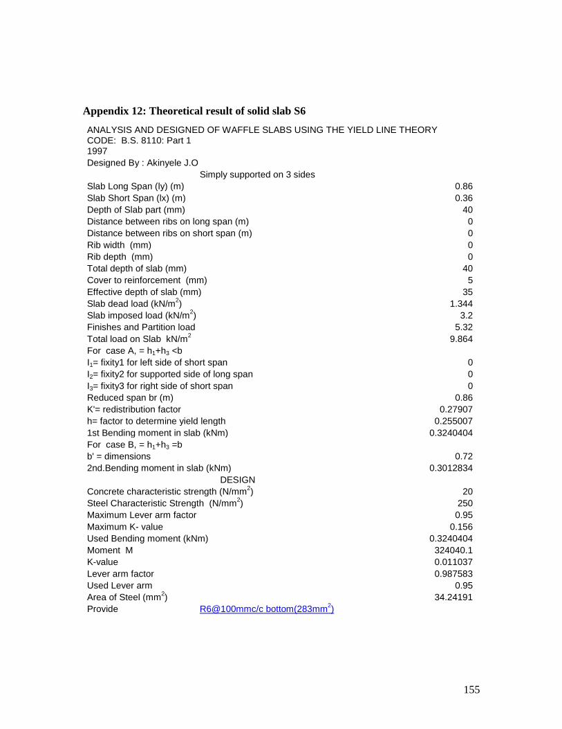
155
Appendix 12: Theoretical result of solid slab S6
ANALYSIS AND DESIGNED OF WAFFLE SLABS USING THE YIELD LINE THEORY CODE: B.S. 8110: Part 1 1997
Designed By : Akinyele J.O
Simply supported on 3 sides
Slab Long Span (ly) (m) 0.86
Slab Short Span (lx) (m) 0.36
Depth of Slab part (mm) 40
Distance between ribs on long span (m) 0
Distance between ribs on short span (m) 0
Rib width (mm) 0
Rib depth (mm) 0
Total depth of slab (mm) 40
Cover to reinforcement (mm) 5
Effective depth of slab (mm) 35
Slab dead load (kN/m2) 1.344
Slab imposed load (kN/m2) 3.2
Finishes and Partition load 5.32
Total load on Slab kN/m2
9.864
For case A, = h1+h3 <b
I1= fixity1 for left side of short span 0
I2= fixity2 for supported side of long span 0
I3= fixity3 for right side of short span 0
Reduced span br (m) 0.86
K'= redistribution factor 0.27907
h= factor to determine yield length 0.255007
1st Bending moment in slab (kNm) 0.3240404
For case B, = h1+h3 =b
b' = dimensions 0.72
2nd.Bending moment in slab (kNm) 0.3012834
DESIGN
Concrete characteristic strength (N/mm2) 20
Steel Characteristic Strength (N/mm2) 250
Maximum Lever arm factor 0.95
Maximum K- value 0.156
Used Bending moment (kNm) 0.3240404
Moment M 324040.1
K-value 0.011037
Lever arm factor 0.987583
Used Lever arm 0.95
Area of Steel (mm2) 34.24191
Provide R6@100mmc/c bottom(283mm2)
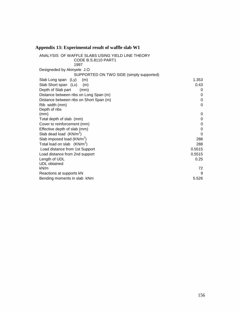
156
Appendix 13: Experimental result of waffle slab W1
ANALYSIS OF WAFFLE SLABS USING YIELD LINE THEORY
CODE B.S.8110 PART1 1997
Designeded by Akinyele J.O
SUPPORTED ON TWO SIDE (simply supported)
Slab Long span (Ly) (m) 1.353
Slab Short span (Lx) (m) 0.43
Depth of Slab part (mm) 0
Distance between ribs on Long Span (m) 0
Distance between ribs on Short Span (m) 0
Rib width (mm) 0 Depth of ribs (mm) 0
Total depth of slab (mm) 0
Cover to reinforcement (mm) 0
Effective depth of slab (mm) 0
Slab dead load (KN/m2) 0
Slab imposed load (KN/m2) 288
Total load on slab (KN/m2) 288
Load distance from 1st Support 0.5515
Load distance from 2nd support 0.5515
Length of UDL 0.25 UDL obtained kN/m 72
Reactions at supports kN 9
Bending moments in slab kNm 5.526

157
Appendix 14: Experimental result of waffle slab W2
ANALYSIS AND DESIGNED OF WAFFLE SLABS USING THE YIELD LINE THEORY.
CODE B.S. 8110: PART 1: 1997. Designed By : Engr. Akinyele J.O
Simply supported on all four sides.
Slab Length(Long span) (ly) (m) 0.9
Slab Width (Short span) (lx) (m) 0.3
Rib width (mm) 0 Distance between ribs on Long span (m) 0 Distance between ribs on Short span (m) 0
Depth of slab portion (mm) 0 Depth of ribs (mm) 0
Total depth of slab (mm) 0
Effective depth of slab (mm) 0
Slab dead load kN/m2
0
Imposed load on slab kN/m2
144
Finishes and Partition load 0
Total load on slab (kN/m2) 1
ANALYSIS OF SLABS. Fixity ratio for continuous supports on any side
Fixity ratio short span left side i1 0
Fixity ratio long span bottom i2 0
Fixity ratio short span right side i3 0
Fixity ratio long span top i4 0 Reduced sides ar' 0.3 Reduced sides br' 0.9
Bending moments in slab (kN.m) 1.121538

158
Appendix 15: Experimental result of waffle slab W3
ANALYSIS OF WAFFLE SLABS USING YIELD LINE THEORY
CODE B.S.8110 PART1 1997
Designed by Akinyele J.O
SUPPORTED ON TWO SIDE (simply supported)
Slab Long span (Ly) (m) 1.085
Slab Short span (Lx) (m) 0.43
Depth of Slab part (mm) 0
Distance between ribs on Long Span (m) 0
Distance between ribs on Short Span (m) 0
Rib width (mm) 0 Depth of ribs (mm) 0
Total depth of slab (mm) 0
Cover to reinforcement (mm) 0
Effective depth of slab (mm) 0
Slab dead load (kN/m2) 0
Slab imposed load (kN/m2) 192
Total load on slab (kN/m2) 192
Load distance from 1st Support 0.4175
Load distance from 2nd support 0.4175
Length of UDL 0.25 UDL obtained kN/m 48
Reactions at supports kN 6
Bending moments in slab kNm 2.88

159
Appendix 16 Experimental result of waffle slab W4
ANALYSIS AND DESIGNED OF WAFFLE SLABS USING THE YIELD LINE THEORY.
CODE B.S. 8110: PART 1: 1997.
Designed By : Engr. Akinyele J.O
Simple supported on all four sides.
Slab Length(Long span) (Ly) (m) 0.407
Slab Width (Short span) (Lx) (m) 0.364 Rib width (mm) 20
Distance between ribs on Long span (m) 0.4
Distance between ribs on Short span (m) 0.4
Depth of slab portion (mm) 0 Depth of ribs (mm) 0
Total depth of slab (mm) 0
Effective depth of slab (mm) 0
Slab dead load kN/m2
0
Imposed load on slab kN/m2
96
Finishes and Partition load 0
Total load on slab (kN/m2) 96
ANALYSIS OF SLABS.
Fixity ratio for continuos supports on any side
Fixity ratio short span left side i1 0
Fixity ratio long span bottom i2 0
Fixity ratio short span rigth side i3 0
Fixity ratio long span top i4 0 Reduced sides ar' 0.364 Reduced sides br' 0.407
Bending moments in slab (kN.m) 0.590137

160
Appendix 17: Experimental result of waffle slab W5
ANALYSIS AND DESIGNED OF WAFFLE SLABS USING THE YIELD LINE THEORY
CODE: B.S. 8110: Part 1 1997
Designed By : Akinyele J.O
Simply supported on 3 sides
Slab Long Span (ly) (m) 1.312
Slab Short Span (lx) (m) 0.3
Depth of Slab part (mm) 0
Distance between ribs on long span (m) 0
Distance between ribs on short span (m) 0
Rib width (mm) 0
Rib depth (mm) 0
Total depth of slab (mm) 0
Cover to reinforcement (mm) 0
Effective depth of slab (mm) 0
Slab dead load (kN/m2) 0
Slab imposed load (kN/m2) 15.01
Finishes and Partition load 5.32
Total load on Slab (kN/m2) 20.33
For case A, = h1+h3 <b
I1= fixity1 for left side of short span 0
I2= fixity2 for supported side of long span 0
I3= fixity3 for right side of short span 0
Reduced span br (m) 1.312
K'= redistribution factor 0.152439
h= factor to determine yield length 0.236725
1st Bending moment in slab (kNm) 0.947269
For case B, = h1+h3 =b
b' = dimensions 0.6
2nd.Bending moment in slab (kNm) 0.657679

161
Appendix 18: Experimental result of waffle slab W6
ANALYSIS AND DESIGNED OF WAFFLE SLABS USING THE YIELD LINE THEORY
CODE: B.S. 8110: Part 1 1997
Designed By : Akinyele J.O
Simply supported on 3 sides
Slab Long Span (ly) (m) 0.86
Slab Short Span (lx) (m) 0.36
Depth of Slab part (mm) 0
Distance between ribs on long span (m) 0
Distance between ribs on short span (m) 0
Rib width (mm) 0
Rib depth (mm) 0
Total depth of slab (mm) 0
Cover to reinforcement (mm) 5
Effective depth of slab (mm) 0
Slab dead load (kN/m2) 0
Slab imposed load (kN/m2) 33.44
Finishes and Partition load 5.32
Total load on Slab (kN/m2) 38.76
For case A, = h1+h3 <b
I1= fixity1 for left side of short span 0
I2= fixity2 for supported side of long span 0
I3= fixity3 for right side of short span 0
Reduced span br (m) 0.86
K'= redistribution factor 0.27907
h= factor to determine yield length 0.255007
1st Bending moment in slab (kNm) 1.27624
For case B, = h1+h3 =b
b' = dimensions 0.72
2nd.Bending moment in slab (kNm) 1.1147

162
Appendix 19: Experimental result of solid slab S1
ANALYSIS OF WAFFLE SLABS USING YIELD LINE THEORY
CODE B.S.8110 PART1 1997
Designed by Akinyele J.O
SUPPORTED ON TWO SIDE (simply supported)
Slab Long span (Ly) (m) 1.353
Slab Short span (Lx) (m) 0.43
Depth of Slab part (mm) 0
Distance between ribs on Long Span (m) 0
Distance between ribs on Short Span (m) 0
Rib width (mm) 0 Depth of ribs (mm) 0
Total depth of slab (mm) 0
Cover to reinforcement (mm) 0
Effective depth of slab (mm) 0
Slab dead load (kN/m2) 0
Slab imposed load (kN/m2) 192
Total load on slab (kN/m2) 192
Load distance from 1st Support 0.5515
Load distance from 2nd support 0.5515
Length of UDL 0.25 UDL obtained kN/m 48
Reactions at supports kN 6
Bending moments in slab kNm 3.684

163
Appendix 20: Experimental result of solid slab S2
ANALYSIS AND DESIGNED OF WAFFLE SLABS USING THE YIELD LINE THEORY.
CODE B.S. 8110: PART 1: 1997.
Designed By : Engr. Akinyele J.O
Simply supported on all four sides.
Slab Length(Long span) (ly) (m) 0.9
Slab Width (Short span) (lx) (m) 0.3
Rib width (mm) 0
Distance between ribs on Long span (m) 0
Distance between ribs on Short span (m) 0
Depth of slab portion (mm) 0
Depth of ribs (mm) 0
Total depth of slab (mm) 0
Effective depth of slab (mm) 0
Slab dead load kN/m2
0
Imposed load on slab kN/m2
112
Finishes and Partition load 0
Total load on slab (kN/m2) 112
ANALYSIS OF SLABS.
Fixity ratio for continuous supports on any side
Fixity ratio short span left side i1 0
Fixity ratio long span bottom i2 0
Fixity ratio short span right side i3 0
Fixity ratio long span top i4 0
Reduced sides ar' 0.3
Reduced sides br' 0.9
Bending moments in slab (kN.m) 0.872308

164
Appendix 21: Experimental result of solid slab S3
ANALYSIS OF WAFFLE SLABS USING YIELD LINE THEORY
CODE B.S.8110 PART1 1997
Designed by Akinyele J.O
SUPPORTED ON TWO SIDE (simply supported)
Slab Long span (Ly) (m) 1.085
Slab Short span (Lx) (m) 0.43
Depth of Slab part (mm) 0
Distance between ribs on Long Span (m) 0
Distance between ribs on Short Span (m) 0
Rib width (mm) 0 Depth of ribs (mm) 0
Total depth of slab (mm) 0
Cover to reinforcement (mm) 0
Effective depth of slab (mm) 0
Slab dead load (kN/m2) 0
Slab imposed load (kN/m2) 244
Total load on slab (kN/m2) 244
Load distance from 1st Support 0.4175
Load distance from 2nd support 0.4175
Length of UDL 0.25 UDL obtained kN/m 56
Reactions at supports kN 7
Bending moments in slab kNm 3.360

165
Appendix 22: Experimental result of solid slab S4
ANALYSIS AND DESIGNED OF WAFFLE SLABS USING THE YIELD LINE THEORY.
CODE B.S. 8110: PART 1: 1997.
Designed By : Engr. Akinyele J.O
Simply supported on all four sides.
Slab Length(Long span) (ly) (m) 0.407
Slab Width (Short span) (lx) (m) 0.364
Rib width (mm) 0
Distance between ribs on Long span (m) 0
Distance between ribs on Short span (m) 0
Depth of slab portion (mm) 0
Depth of ribs (mm) 0
Total depth of slab (mm) 0
Effective depth of slab (mm) 0
Slab dead load kN/m2
0
Imposed load on slab kN/m2
96
Finishes and Partition load 0
Total load on slab (KN/m2) 96
ANALYSIS OF SLABS.
Fixity ratio for continuous supports on any side
Fixity ratio short span left side i1 0
Fixity ratio long span bottom i2 0
Fixity ratio short span right side i3 0
Fixity ratio long span top i4 0
Reduced sides ar' 0.364
Reduced sides br' 0.407
Bending moments in slab (kN.m) 0.590152
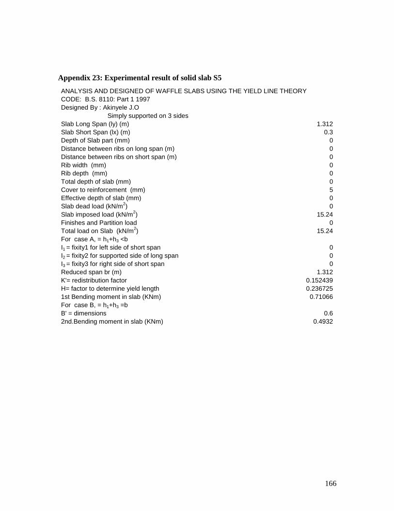
166
Appendix 23: Experimental result of solid slab S5
ANALYSIS AND DESIGNED OF WAFFLE SLABS USING THE YIELD LINE THEORY
CODE: B.S. 8110: Part 1 1997
Designed By : Akinyele J.O
Simply supported on 3 sides
Slab Long Span (ly) (m) 1.312
Slab Short Span (lx) (m) 0.3
Depth of Slab part (mm) 0
Distance between ribs on long span (m) 0
Distance between ribs on short span (m) 0
Rib width (mm) 0
Rib depth (mm) 0
Total depth of slab (mm) 0
Cover to reinforcement (mm) 5
Effective depth of slab (mm) 0
Slab dead load (kN/m2) 0
Slab imposed load (kN/m2) 15.24
Finishes and Partition load 0
Total load on Slab (kN/m2) 15.24
For case A, = h1+h3 <b
I1 = fixity1 for left side of short span 0
I2 = fixity2 for supported side of long span 0
I3 = fixity3 for right side of short span 0
Reduced span br (m) 1.312
K'= redistribution factor 0.152439
H= factor to determine yield length 0.236725
1st Bending moment in slab (KNm) 0.71066
For case B, = h1+h3 =b
B' = dimensions 0.6
2nd.Bending moment in slab (KNm) 0.4932
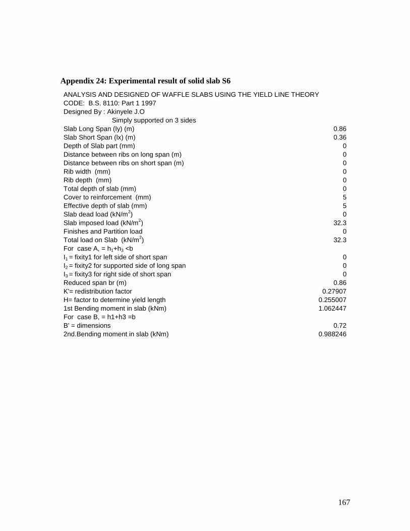
167
Appendix 24: Experimental result of solid slab S6
ANALYSIS AND DESIGNED OF WAFFLE SLABS USING THE YIELD LINE THEORY
CODE: B.S. 8110: Part 1 1997
Designed By : Akinyele J.O
Simply supported on 3 sides
Slab Long Span (ly) (m) 0.86
Slab Short Span (lx) (m) 0.36
Depth of Slab part (mm) 0
Distance between ribs on long span (m) 0
Distance between ribs on short span (m) 0
Rib width (mm) 0
Rib depth (mm) 0
Total depth of slab (mm) 0
Cover to reinforcement (mm) 5
Effective depth of slab (mm) 5
Slab dead load (kN/m2) 0
Slab imposed load (kN/m2) 32.3
Finishes and Partition load 0
Total load on Slab (kN/m2) 32.3
For case A, = h1+h3 <b
I1 = fixity1 for left side of short span 0
I2 = fixity2 for supported side of long span 0
I3 = fixity3 for right side of short span 0
Reduced span br (m) 0.86
K'= redistribution factor 0.27907
H= factor to determine yield length 0.255007
1st Bending moment in slab (kNm) 1.062447
For case B, = h1+h3 =b
B' = dimensions 0.72
2nd.Bending moment in slab (kNm) 0.988246

168
Appendix 25: Result of waffle slab using the example in Mosley et all
ANALYSIS AND DESIGNED OF WAFFLE SLABS USING THE YIELD LINE THEORY.
CODE B.S. 8110: PART 1: 1997.
Designed By : Engr. Akinyele J.O
Simple supported on all four sides.
Slab Length(Long span) (ly) (m) 6
Slab Width (Short span) (lx) (m) 5
Rib width (mm) 125
Distance between ribs on Long span (m) 0.4
Distance between ribs on Short span (m) 0.4
Depth of slab portion (mm) 60
Depth of ribs (mm) 140
Total depth of slab (mm) 200
Effective depth of slab (mm) 40
Slab dead load kN/m2
2.016
Imposed load on slab kN/m2
10.384
Finishes and Partition load 0
Total load on slab (kN/m2) 12.4
ANALYSIS OF SLABS.
Fixity ratio for continuous supports on any side
Fixity ratio short span left side i1 1
Fixity ratio long span bottom i2 1
Fixity ratio short span right side i3 1
Fixity ratio long span top i4 1
Reduced sides ar' 3.535534
Reduced sides br' 4.242641
Bending moments in slab (KN.m) 7.664835
DESIGN
Cover to reinforcement. (mm) 20
Concrete characteristic stress (N/mm2) 30
Steel Characteristic Stress (N/mm2) 460
Maximum lever arm factor 0.95
Maximum K- Value 0.156
Moment M 7664835
K- value 0.159684
Lever arm factor 0.769394
Used Lever arm 0.769394
Area of steel (mm2) 461.5702
Provide T8@100mmc/c(503mm2)
ANALYSIS AND DESIGN OF RIBS.
Adopting the Rankine Grashoff Theory.
Number of Ribs on Long Span (ly) 10
Number of Ribs on Short Span (lx) 8

169
Weight of Slabs (kN/m2) 1.44
Total Load on Slab (kN) 43.2
Weight of Ribs (kN/m) 0.42
Total weight of Ribs on long span (ly), (kN) 25.2
Total weight of Ribs on Short span (lx), (kN) 16.8
Total weight of Finishes (kN) 30
Total Live Load (kN) 45
Total Load on grid floor (KN) 160.2
Q=Load per Area (m2) 5.34
Denominator for qx and qy 1921
Load sheared on short span (qx), (kN/m2) 3.602624
Load sheared on Long span (qy), (kN/m2) 1.737376
Moment on short span Mx (kN.m) 4.50328
Moment on long span My (kN.m) 3.127277
Shear force on short span, Vx, (kN) 3.602624
Shear force on long span, Vy, (kN) 2.084852
DESIGNED
Steel characteristic stress (N/mm2) 460
Short span Designed moment (Nmm) 4503280
Cover to ribs (mm) 40
Effective depth of ribs 100
K.value 0.120087
Lever arm Factor 0.841423
Used Lever arm 0.841423
Area of Steel (mm2) 122.471
Provide 2T10@ bottom(157mm2)
Long span Designed moment (Nmm) 3127277
K.value 0.083394
Lever arm Factor 0.896661
Used Lever arm 0.896661
Area of Steel (mm2) 79.80989
Provide 2T10 Near bottom (157mm2)
END DESIGNED

170
Appendix 26: Waffle slab result of Mosley et all. Adopting BS 8110 coefficients.
Length = 6m
Breadth = 5m
Total depth of waffle slab = 200mm
Depth of slab portion= 60mm
Depth of ribs= 140mm
Cover to reinforcements= 40mm
Effective depth = 160mm
Spacing between ribs in both axis= 400mm
Designed ultimate load = 12.4kN/m2
Slab is an internal panel of a floor system
Using the slab coefficient of Table 3.14 of BS 8110.
Ly/lx = 6/5 = 1.2
βsx = +0.032
βsy = + 0.024
Moment at mid span along short span = 0.032 x 12.4 x 52 = 9.92kN/m/m
Moment carried by each rib= 0.4 x 9.92 = 3.97kNm
013.030160400
1097.32
6
2
xx
x
fbd
m
cu
26
6016095.046095.0
1097.3
95.0mm
xxx
x
zf
mA
y
s
Provide Two T10 bars in each rib along the small span.
Moment at Mid span along long span = 0.024 x 12.4 x 52=7.44kNm/m
Moment carried by each rib = 0.4 x 7.44= 2.98kNm
009.030160400
1098.22
6
2
xx
x
fbd
m
cu
mmxxx
x
zf
mA
y
s 4516095.046095.0
1098.2
95.0
6

171
Provide Two T10 bars in each rib along the Long span.
Reinforcements at the top flange (slab portion)
As= 0.12 x b x h/100 = 0.12 x 1000 x 60/100 = 72mm2 /m.
Provide D98 Mesh (98mm2).
Shear
From table 3.15 of BS 8110, the shear force coefficient for a continuous edge supports is
0.33. Hence, for one rib, the shear at supports
Vsx = βvxnlx x b = 0.33 x 12.4 x 5 x 0.4 = 8.18kN.
Maximum shear in the rib 0.6m from the centre line is
V = 8.18 – 0.6 x 12.4 x 0.4 = 5.20kN.

172
Appendix 27: Result of waffle W1 Theoretical (ETABS)
ETABS v9.0.0 File:WAFFLE W1THEORY Units:kN-m
PROJECT INFORMATION
Company Name = eng
ETABS v9.0.0 File:WAFFLE W1THEORY Units:kN-m
S T O R Y D A T A
STORY SIMILAR TO HEIGHT ELEVATION
STORY1 None 0.750 0.750
BASE None 0.000
ETABS v9.0.0 File:WAFFLE W1THEORY Units:kN-m
S T A T I C L O A D C A S E S
STATIC CASE AUTO LAT SELF WT
CASE TYPE LOAD MULTIPLIER
DEAD DEAD N/A 0.1000
LIVE REDUCE LIVE N/A 0.0000
ETABS v9.0.0 File:WAFFLE W1THEORY Units:kN-m
M A S S S O U R C E D A T A
MASS LATERAL LUMP MASS
FROM MASS ONLY AT STORIES
Masses Yes Yes
ETABS v9.0.0 File:WAFFLE W1THEORY Units:kN-m
D I A P H R A G M M A S S D A T A
STORY DIAPHRAGM MASS-X MASS-Y MMI X-M Y-M
STORY1 D1 3.0170 3.0170 1.1743 0.677 0.215
ETABS v9.0.0 File:WAFFLE W1THEORY Units:kN-m
A S S E M B L E D P O I N T M A S S E S
STORY UX UY UZ RX RY RZ
STORY1 3.017041 3.017041 0.0000 0.0000 0.000000 1.174264
BASE 0.752728 0.752728 0.000000 0.0000 0.000000 0.000000
Totals 3.769769 3.769769 0.000000 0.0000 0.000000 1.174264

173
ETABS v9.0.0 File:WAFFLE W1THEORY Units:kN-m May 9, 2009 4:47
C E N T E R S O F C U M U L A T I V E M A S S & C E N T E R
S O F R I G I D I T Y
STORY DIAPHRAGM /----------CENTRE OF MASS----------//--CENTRE
OF RIGIDITY--/
LEVEL NAME MASS ORDINATE-X ORDINATE-Y
ORDINATE-X ORDINATE-Y
STORY1 D1 3.0170 0.677 0.215
0.676 0.215
ETABS v9.0.0 File:WAFFLE W1THEORY Units:kN-m May 9, 2009 4:47
M O D A L P E R I O D S A N D F R E Q U E N C I E S
MODE PERIOD FREQUENCY CIRCULAR FREQ
NUMBER (TIME) (CYCLES/TIME) (RADIANS/TIME)
Mode 1 0.01249 80.04585 502.94288
Mode 2 0.01096 91.26274 573.42070
Mode 3 0.00990 101.02017 634.72843
ETABS v9.0.0 File:WAFFLE W1THEORY Units:KN-m
M O D A L P A R T I C I P A T I N G M A S S R A T I O S
MODE X-TRANS Y-TRANS Z-TRANS RX-
ROTN RY-ROTN RZ-ROTN
NUMBER %MASS <SUM> %MASS <SUM> %MASS <SUM> %MASS
<SUM> %MASS <SUM> %MASS <SUM>
Mode 1 0.00 < 0> 100.00 <100> 0.00 < 0> 100.00
<100> 0.00 < 0> 0.00 < 0>
Mode 2 100.00 <100> 0.00 <100> 0.00 < 0> 0.00
<100> 100.00 <100> 0.00 < 0>
Mode 3 0.00 <100> 0.00 <100> 0.00 < 0> 0.00
<100> 0.00 <100> 100.00 <100>
ETABS v9.0.0 File:WAFFLE W1THEORY Units:kN-m
M O D A L L O A D P A R T I C I P A T I O N R A T I O S
(STATIC AND DYNAMIC RATIOS ARE IN PERCENT)
TYPE NAME STATIC DYNAMIC
Load DEAD 0.0000 0.0000
Load LIVE 0.0000 0.0000
Accel UX 100.0000 100.0000
Accel UY 100.0000 100.0000
Accel UZ 0.0000 0.0000
Accel RX 100.0000 100.0000

174
Accel RY 100.0000 100.0000
Accel RZ 100.0000 100.0000
ETABS v9.0.0 File:WAFFLE W1THEORY Units:KN-m
TOTAL REACTIVE FORCES (RECOVERED LOADS) AT ORIGIN
LOAD FX FY FZ MX MY MZ
DEAD 0.00 0.00 7.10 1.525 -4.800 0.00
LIVE 0.00 0.00 1.86 0.400 -1.259 0.000

175
Appendix 28: Result of waffle W2 Theoretical (ETABS)
ETABS v9.0.0 File:WAFFLE W2THEORY Units:kN-m
PROJECT INFORMATION
Company Name = eng
ETABS v9.0.0 File:WAFFLE W2THEORY Units:kN-m
S T O R Y D A T A
STORY SIMILAR TO HEIGHT ELEVATION
STORY1 None 0.750 0.750
BASE None 0.000
ETABS v9.0.0 File:WAFFLE W2THEORY Units:kN-m
S T A T I C L O A D C A S E S
STATIC CASE AUTO LAT SELF WT
CASE TYPE LOAD MULTIPLIER
DEAD DEAD N/A 0.1000
LIVE REDUCE LIVE N/A 0.0000
ETABS v9.0.0 File:WAFFLE W2THEORY Units:kN-m
M A S S S O U R C E D A T A
MASS LATERAL LUMP MASS
FROM MASS ONLY AT STORIES
Masses Yes Yes
ETABS v9.0.0 File:WAFFLE W2THEORY Units:kN-m
D I A P H R A G M M A S S D A T A
STORY DIAPHRAGM MASS-X MASS-Y MMI X-M Y-M
STORY1 D1 2.2222 2.2222 0.4092 0.450 0.150
ETABS v9.0.0 File:WAFFLE W2THEORY Units:kN-m
A S S E M B L E D P O I N T M A S S E S
STORY UX UY UZ RX RY RZ
STORY1 2.222178 2.222178 0.000000 0.000000 0.000000 0.409217
BASE 0.752728 0.752728 0.000000 0.000000 0.000000 0.000000
Totals 2.974906 2.974906 0.000000 0.000000 0.000000 0.409217
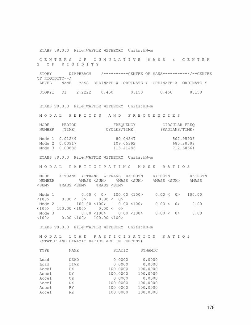
176
ETABS v9.0.0 File:WAFFLE W2THEORY Units:kN-m
C E N T E R S O F C U M U L A T I V E M A S S & C E N T E R
S O F R I G I D I T Y
STORY DIAPHRAGM /----------CENTRE OF MASS----------//--CENTRE
OF RIGIDITY--/
LEVEL NAME MASS ORDINATE-X ORDINATE-Y ORDINATE-X ORDINATE-Y
STORY1 D1 2.2222 0.450 0.150 0.450 0.150
ETABS v9.0.0 File:WAFFLE W2THEORY Units:kN-m
M O D A L P E R I O D S A N D F R E Q U E N C I E S
MODE PERIOD FREQUENCY CIRCULAR FREQ
NUMBER (TIME) (CYCLES/TIME) (RADIANS/TIME)
Mode 1 0.01249 80.04847 502.95938
Mode 2 0.00917 109.05392 685.20598
Mode 3 0.00882 113.41486 712.60661
ETABS v9.0.0 File:WAFFLE W2THEORY Units:kN-m
M O D A L P A R T I C I P A T I N G M A S S R A T I O S
MODE X-TRANS Y-TRANS Z-TRANS RX-ROTN RY-ROTN RZ-ROTN
NUMBER %MASS <SUM> %MASS <SUM> %MASS <SUM> %MASS
<SUM> %MASS <SUM> %MASS <SUM>
Mode 1 0.00 < 0> 100.00 <100> 0.00 < 0> 100.00
<100> 0.00 < 0> 0.00 < 0>
Mode 2 100.00 <100> 0.00 <100> 0.00 < 0> 0.00
<100> 100.00 <100> 0.00 < 0>
Mode 3 0.00 <100> 0.00 <100> 0.00 < 0> 0.00
<100> 0.00 <100> 100.00 <100>
ETABS v9.0.0 File:WAFFLE W2THEORY Units:kN-m
M O D A L L O A D P A R T I C I P A T I O N R A T I O S
(STATIC AND DYNAMIC RATIOS ARE IN PERCENT)
TYPE NAME STATIC DYNAMIC
Load DEAD 0.0000 0.0000
Load LIVE 0.0000 0.0000
Accel UX 100.0000 100.0000
Accel UY 100.0000 100.0000
Accel UZ 0.0000 0.0000
Accel RX 100.0000 100.0000
Accel RY 100.0000 100.0000
Accel RZ 100.0000 100.0000

177
ETABS v9.0.0 File:WAFFLE W2THEORY Units:kN-m
TOTAL REACTIVE FORCES (RECOVERED LOADS) AT ORIGIN
LOAD FX FY FZ MX MY MZ
DEAD 0.00 0.00 3.11 0.467 -1.401 0.000
LIVE 0.00 0.00 0.23 0.035 -0.105 0.000

178
Appendix 29: Result of waffle W3 Theoretical (ETABS)
ETABS v9.0.0 File:WAFFLE W3 THEORY Units:kN-m
PROJECT INFORMATION
Company Name = eng
ETABS v9.0.0 File:WAFFLE W3 THEORY Units:kN-m
S T O R Y D A T A
STORY SIMILAR TO HEIGHT ELEVATION
STORY1 None 0.750 0.750
BASE None 0.000
ETABS v9.0.0 File:WAFFLE W3 THEORY Units:kN-m
S T A T I C L O A D C A S E S
STATIC CASE AUTO LAT SELF WT
CASE TYPE LOAD MULTIPLIER
DEAD DEAD N/A 0.1000
LIVE REDUCE LIVE N/A 0.0000
ETABS v9.0.0 File:WAFFLE W3 THEORY Units:kN-m
M A S S S O U R C E D A T A
MASS LATERAL LUMP MASS
FROM MASS ONLY AT STORIES
Masses Yes Yes
ETABS v9.0.0 File:WAFFLE W3 THEORY Units:kN-m
D I A P H R A G M M A S S D A T A
STORY DIAPHRAGM MASS-X MASS-Y MMI X-M Y-M
STORY1 D1 2.5350 2.5350 0.6810 0.543 0.215
ETABS v9.0.0 File:WAFFLE W3 THEORY Units:kN-m
A S S E M B L E D P O I N T M A S S E S
STORY UX UY UZ RX RY RZ
STORY1 2.535048 2.535048 0.000000 0.000000 0.000 0.680962
BASE 0.752728 0.752728 0.000000 0.000000 0.0000 0.000000
Totals 3.287776 3.287776 0.000000 0.000000 0.0000 0.680962
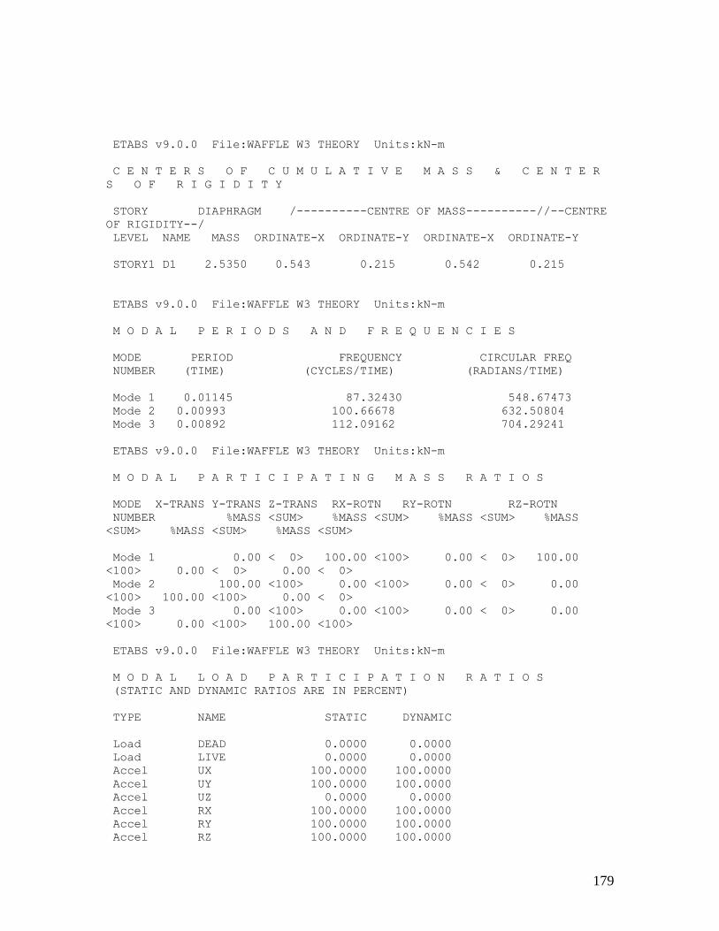
179
ETABS v9.0.0 File:WAFFLE W3 THEORY Units:kN-m
C E N T E R S O F C U M U L A T I V E M A S S & C E N T E R
S O F R I G I D I T Y
STORY DIAPHRAGM /----------CENTRE OF MASS----------//--CENTRE
OF RIGIDITY--/
LEVEL NAME MASS ORDINATE-X ORDINATE-Y ORDINATE-X ORDINATE-Y
STORY1 D1 2.5350 0.543 0.215 0.542 0.215
ETABS v9.0.0 File:WAFFLE W3 THEORY Units:kN-m
M O D A L P E R I O D S A N D F R E Q U E N C I E S
MODE PERIOD FREQUENCY CIRCULAR FREQ
NUMBER (TIME) (CYCLES/TIME) (RADIANS/TIME)
Mode 1 0.01145 87.32430 548.67473
Mode 2 0.00993 100.66678 632.50804
Mode 3 0.00892 112.09162 704.29241
ETABS v9.0.0 File:WAFFLE W3 THEORY Units:kN-m
M O D A L P A R T I C I P A T I N G M A S S R A T I O S
MODE X-TRANS Y-TRANS Z-TRANS RX-ROTN RY-ROTN RZ-ROTN
NUMBER %MASS <SUM> %MASS <SUM> %MASS <SUM> %MASS
<SUM> %MASS <SUM> %MASS <SUM>
Mode 1 0.00 < 0> 100.00 <100> 0.00 < 0> 100.00
<100> 0.00 < 0> 0.00 < 0>
Mode 2 100.00 <100> 0.00 <100> 0.00 < 0> 0.00
<100> 100.00 <100> 0.00 < 0>
Mode 3 0.00 <100> 0.00 <100> 0.00 < 0> 0.00
<100> 0.00 <100> 100.00 <100>
ETABS v9.0.0 File:WAFFLE W3 THEORY Units:kN-m
M O D A L L O A D P A R T I C I P A T I O N R A T I O S
(STATIC AND DYNAMIC RATIOS ARE IN PERCENT)
TYPE NAME STATIC DYNAMIC
Load DEAD 0.0000 0.0000
Load LIVE 0.0000 0.0000
Accel UX 100.0000 100.0000
Accel UY 100.0000 100.0000
Accel UZ 0.0000 0.0000
Accel RX 100.0000 100.0000
Accel RY 100.0000 100.0000
Accel RZ 100.0000 100.0000
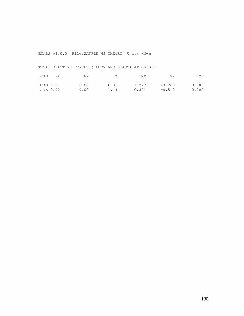
180
ETABS v9.0.0 File:WAFFLE W3 THEORY Units:kN-m
TOTAL REACTIVE FORCES (RECOVERED LOADS) AT ORIGIN
LOAD FX FY FZ MX MY MZ
DEAD 0.00 0.00 6.01 1.292 -3.260 0.000
LIVE 0.00 0.00 1.49 0.321 -0.810 0.000

181
Appendix 30: Result of waffle W4 Theoretical (ETABS)
ETABS v9.0.0 File:WAFFLE W4THEORY Units:kN-m
PROJECT INFORMATION
Company Name = eng
ETABS v9.0.0 File:WAFFLE W4THEORY Units:kN-m
S T O R Y D A T A
STORY SIMILAR TO HEIGHT ELEVATION
STORY1 None 0.750 0.750
BASE None 0.000
ETABS v9.0.0 File:WAFFLE W4THEORY Units:kN-m
S T A T I C L O A D C A S E S
STATIC CASE AUTO LAT SELF WT
CASE TYPE LOAD MULTIPLIER
DEAD DEAD N/A 0.1000
LIVE REDUCE LIVE N/A 0.0000
ETABS v9.0.0 File:WAFFLE W4THEORY Units:kN-m
M A S S S O U R C E D A T A
MASS LATERAL LUMP MASS
FROM MASS ONLY AT STORIES
Masses Yes Yes
ETABS v9.0.0 File:WAFFLE W4THEORY Units:kN-m
D I A P H R A G M M A S S D A T A
STORY DIAPHRAGM MASS-X MASS-Y MMI X-M Y-M
STORY1 D1 1.6142 1.6142 0.1072 0.204 0.182
ETABS v9.0.0 File:WAFFLE W4THEORY Units:kN-m
A S S E M B L E D P O I N T M A S S E S
STORY UX UY UZ RX RY RZ
STORY1 1.614198 1.614198 0.000000 0.000000 0.000000 0.107212
BASE 0.752728 0.752728 0.000000 0.000000 0.000000 0.000000
Totals 2.366926 2.366926 0.000000 0.000000 0.000000 0.107212

182
ETABS v9.0.0 File:WAFFLE W4THEORY Units:kN-m
C E N T E R S O F C U M U L A T I V E M A S S & C E N T E R
S O F R I G I D I T Y
STORY DIAPHRAGM /----------CENTRE OF MASS----------//--CENTRE OF
RIGIDITY--/
LEVEL NAME MASS ORDINATE-X ORDINATE-Y ORDINATE-X ORDINATE-Y
STORY1 D1 1.6142 0.204 0.182 0.203 0.182
ETABS v9.0.0 File:WAFFLE W4THEORY Units:kN-m
M O D A L P E R I O D S A N D F R E Q U E N C I E S
MODE PERIOD FREQUENCY CIRCULAR FREQ
NUMBER (TIME) (CYCLES/TIME) (RADIANS/TIME)
Mode 1 0.00974 102.65408 644.99462
Mode 2 0.00934 107.10545 672.96340
Mode 3 0.00686 145.86851 916.51886
ETABS v9.0.0 File:WAFFLE W4THEORY Units:kN-m
M O D A L P A R T I C I P A T I N G M A S S R A T I O S
MODE X-TRANS Y-TRANS Z-TRANS RX-ROTN RY-ROTN RZ-ROTN
NUMBER %MASS <SUM> %MASS <SUM> %MASS <SUM> %MASS
<SUM> %MASS <SUM> %MASS <SUM>
Mode 1 0.00 < 0> 100.00 <100> 0.00 < 0> 100.00
<100> 0.00 < 0> 0.00 < 0>
Mode 2 100.00 <100> 0.00 <100> 0.00 < 0> 0.00
<100> 100.00 <100> 0.00 < 0>
Mode 3 0.00 <100> 0.00 <100> 0.00 < 0> 0.00
<100> 0.00 <100> 100.00 <100>
ETABS v9.0.0 File:WAFFLE W4THEORY Units:kN-m
M O D A L L O A D P A R T I C I P A T I O N R A T I O S
(STATIC AND DYNAMIC RATIOS ARE IN PERCENT)
TYPE NAME STATIC DYNAMIC
Load DEAD 0.0000 0.0000
Load LIVE 0.0000 0.0000
Accel UX 100.0000 100.0000
Accel UY 100.0000 100.0000
Accel UZ 0.0000 0.0000
Accel RX 100.0000 100.0000
Accel RY 100.0000 100.0000

183
Accel RZ 100.0000 100.0000
ETABS v9.0.0 File:WAFFLE W4THEORY Units:kN-m
TOTAL REACTIVE FORCES (RECOVERED LOADS) AT ORIGIN
LOAD FX FY FZ MX MY MZ
DEAD 0.00 0.00 2.32 0.422 -0.473 0.000
LIVE 0.00 0.00 0.03 0.005 -0.005 0.000

184
Appendix 31: Result of waffle W5 Theoretical (ETABS)
ETABS v9.0.0 File:WAFFLE W5THEORY Units:kN-m
PROJECT INFORMATION
Company Name = eng
ETABS v9.0.0 File:WAFFLE W5THEORY Units:kN-m
S T O R Y D A T A
STORY SIMILAR TO HEIGHT ELEVATION
STORY1 None 0.750 0.750
BASE None 0.000
ETABS v9.0.0 File:WAFFLE W5THEORY Units:kN-m
S T A T I C L O A D C A S E S
STATIC CASE AUTO LAT SELF WT
CASE TYPE LOAD MULTIPLIER
DEAD DEAD N/A 0.1000
LIVE REDUCE LIVE N/A 0.0000
ETABS v9.0.0 File:WAFFLE W5THEORY Units:kN-m
M A S S S O U R C E D A T A
MASS LATERAL LUMP MASS
FROM MASS ONLY AT STORIES
Masses Yes Yes
ETABS v9.0.0 File:WAFFLE W5THEORY Units:kN-m
D I A P H R A G M M A S S D A T A
STORY DIAPHRAGM MASS-X MASS-Y MMI X-M Y-M
STORY1 D1 2.0627 2.0627 0.7605 0.656 0.150
ETABS v9.0.0 File:WAFFLE W5THEORY Units:kN-m
A S S E M B L E D P O I N T M A S S E S
STORY UX UY UZ RX RY RZ
STORY1 2.062712 2.062712 0.000000 0.000000 0.000000 0.760534
BASE 0.752728 0.752728 0.000000 0.000000 0.000000 0.000000
Totals 2.815440 2.815440 0.000000 0.000000 0.000000 0.760534

185
ETABS v9.0.0 File:WAFFLE W5THEORY Units:kN-m
C E N T E R S O F C U M U L A T I V E M A S S & C E N T E R
S O F R I G I D I T Y
STORY DIAPHRAGM /----------CENTRE OF MASS----------//--CENTRE
OF RIGIDITY--/
LEVEL NAME MASS ORDINATE-X ORDINATE-Y ORDINATE-X ORDINATE-Y
STORY1 D1 2.0627 0.656 0.150 0.656 0.150
ETABS v9.0.0 File:WAFFLE W5THEORY Units:kN-m
M O D A L P E R I O D S A N D F R E Q U E N C I E S
MODE PERIOD FREQUENCY CIRCULAR FREQ
NUMBER (TIME) (CYCLES/TIME) (RADIANS/TIME)
Mode 1 0.01247 80.18465 503.81500
Mode 2 0.00954 104.83219 658.68006
Mode 3 0.00954 104.87250 658.93333
ETABS v9.0.0 File:WAFFLE W5THEORY Units:kN-m
M O D A L P A R T I C I P A T I N G M A S S R A T I O S
MODE X-TRANS Y-TRANS Z-TRANS RX-ROTN RY-ROTN RZ-ROTN
NUMBER %MASS <SUM> %MASS <SUM> %MASS <SUM> %MASS
<SUM> %MASS <SUM> %MASS <SUM>
Mode 1 0.00 < 0> 100.00 <100> 0.00 < 0> 100.00
<100> 0.00 < 0> 0.00 < 0>
Mode 2 100.00 <100> 0.00 <100> 0.00 < 0> 0.00
<100> 100.00 <100> 0.00 < 0>
Mode 3 0.00 <100> 0.00 <100> 0.00 < 0> 0.00
<100> 0.00 <100> 100.00 <100>
ETABS v9.0.0 File:WAFFLE W5THEORY Units:kN-m
M O D A L L O A D P A R T I C I P A T I O N R A T I O S
(STATIC AND DYNAMIC RATIOS ARE IN PERCENT)
TYPE NAME STATIC DYNAMIC
Load DEAD 0.0000 0.0000
Load LIVE 0.0000 0.0000
Accel UX 100.0000 100.0000
Accel UY 100.0000 100.0000
Accel UZ 0.0000 0.0000
Accel RX 100.0000 100.0000
Accel RY 100.0000 100.0000
Accel RZ 100.0000 100.0000
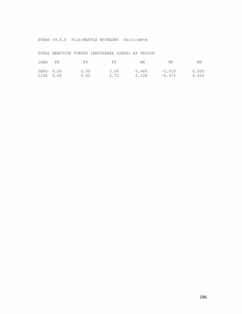
186
ETABS v9.0.0 File:WAFFLE W5THEORY Units:kN-m
TOTAL REACTIVE FORCES (RECOVERED LOADS) AT ORIGIN
LOAD FX FY FZ MX MY MZ
DEAD 0.00 0.00 3.06 0.460 -2.010 0.000
LIVE 0.00 0.00 0.72 0.108 -0.473 0.000

187
Appendix 32: Result of waffle W6 Theoretical (ETABS)
ETABS v9.0.0 File:WAFFLE W6THEORY Units:kN-m
PROJECT INFORMATION
Company Name = eng
ETABS v9.0.0 File:WAFFLE W6THEORY Units:kN-m
S T O R Y D A T A
STORY SIMILAR TO HEIGHT ELEVATION
STORY1 None 0.750 0.750
BASE None 0.000
ETABS v9.0.0 File:WAFFLE W6THEORY Units:kN-m
S T A T I C L O A D C A S E S
STATIC CASE AUTO LAT SELF WT
CASE TYPE LOAD MULTIPLIER
DEAD DEAD N/A 0.1000
LIVE REDUCE LIVE N/A 0.0000
ETABS v9.0.0 File:WAFFLE W6THEORY Units:kN-m
M A S S S O U R C E D A T A
MASS LATERAL LUMP MASS
FROM MASS ONLY AT STORIES
Masses Yes Yes
ETABS v9.0.0 File:WAFFLE W6THEORY Units:kN-m
D I A P H R A G M M A S S D A T A
STORY DIAPHRAGM MASS-X MASS-Y MMI X-M Y-M
STORY1 D1 1.6898 1.6898 0.3085 0.430 0.180
ETABS v9.0.0 File:WAFFLE W6THEORY Units:kN-m
A S S E M B L E D P O I N T M A S S E S
STORY UX UY UZ RX RY RZ
STORY1 1.689796 1.689796 0.000000 0.000000 0.000000 0.308515
BASE 0.752728 0.752728 0.000000 0.000000 0.000000 0.000000
Totals 2.442524 2.442524 0.000000 0.000000 0.000000 0.308515

188
ETABS v9.0.0 File:WAFFLE W6THEORY Units:kN-m
C E N T E R S O F C U M U L A T I V E M A S S & C E N T E R
S O F R I G I D I T Y
STORY DIAPHRAGM /----------CENTRE OF MASS----------//--CENTRE OF
RIGIDITY--/
LEVEL NAME MASS ORDINATE-X ORDINATE-Y ORDINATE-X ORDINATE-Y
STORY1 D1 1.6898 0.430 0.180 0.430 0.180
ETABS v9.0.0 File:WAFFLE W6THEORY Units:kN-m
M O D A L P E R I O D S A N D F R E Q U E N C I E S
MODE PERIOD FREQUENCY CIRCULAR FREQ
NUMBER (TIME) (CYCLES/TIME) (RADIANS/TIME)
Mode 1 0.01037 96.47473 606.16863
Mode 2 0.00834 119.94595 753.64261
Mode 3 0.00780 128.27638 805.98424
ETABS v9.0.0 File:WAFFLE W6THEORY Units:kN-m
M O D A L P A R T I C I P A T I N G M A S S R A T I O S
MODE X-TRANS Y-TRANS Z-TRANS RX-ROTN RY-ROTN RZ-ROTN
NUMBER %MASS <SUM> %MASS <SUM> %MASS <SUM> %MASS
<SUM> %MASS <SUM> %MASS <SUM>
Mode 1 0.00 < 0> 100.00 <100> 0.00 < 0> 100.00
<100> 0.00 < 0> 0.00 < 0>
Mode 2 100.00 <100> 0.00 <100> 0.00 < 0> 0.00
<100> 100.00 <100> 0.00 < 0>
Mode 3 0.00 <100> 0.00 <100> 0.00 < 0> 0.00
<100> 0.00 <100> 100.00 <100>
ETABS v9.0.0 File:WAFFLE W6THEORY Units:kN-m
M O D A L L O A D P A R T I C I P A T I O N R A T I O S
(STATIC AND DYNAMIC RATIOS ARE IN PERCENT)
TYPE NAME STATIC DYNAMIC
Load DEAD 0.0000 0.0000
Load LIVE 0.0000 0.0000
Accel UX 100.0000 100.0000
Accel UY 100.0000 100.0000
Accel UZ 0.0000 0.0000
Accel RX 100.0000 100.0000
Accel RY 100.0000 100.0000
Accel RZ 100.0000 100.0000
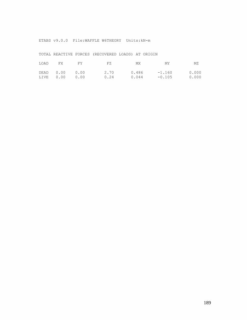
189
ETABS v9.0.0 File:WAFFLE W6THEORY Units:kN-m
TOTAL REACTIVE FORCES (RECOVERED LOADS) AT ORIGIN
LOAD FX FY FZ MX MY MZ
DEAD 0.00 0.00 2.70 0.486 -1.160 0.000
LIVE 0.00 0.00 0.24 0.044 -0.105 0.000

190
Appendix 33: Result of waffle W1 Experimental (ETABS)
ETABS v9.0.0 File:WAFFLE W1EXPERIMENT Units:kN-m
PROJECT INFORMATION
Company Name = eng
ETABS v9.0.0 File:WAFFLE W1EXPERIMENT Units:kN-m
S T O R Y D A T A
STORY SIMILAR TO HEIGHT ELEVATION
STORY1 None 0.750 0.750
BASE None 0.000
ETABS v9.0.0 File:WAFFLE W1EXPERIMENT Units:kN-m
S T A T I C L O A D C A S E S
STATIC CASE AUTO LAT SELF WT
CASE TYPE LOAD MULTIPLIER
DEAD DEAD N/A 0.1000
LIVE REDUCE LIVE N/A 0.0000
ETABS v9.0.0 File:WAFFLE W1EXPERIMENT Units:kN-m
M A S S S O U R C E D A T A
MASS LATERAL LUMP MASS
FROM MASS ONLY AT STORIES
Masses Yes Yes
ETABS v9.0.0 File:WAFFLE W1EXPERIMENT Units:kN-m
D I A P H R A G M M A S S D A T A
STORY DIAPHRAGM MASS-X MASS-Y MMI X-M Y-M
STORY1 D1 3.0170 3.0170 1.1743 0.677 0.215
ETABS v9.0.0 File:WAFFLE W1EXPERIMENT Units:kN-m

191
A S S E M B L E D P O I N T M A S S E S
STORY UX UY UZ RX RY RZ
STORY1 3.017041 3.017041 0.000000 0.000000 0.000000 1.174264
BASE 0.752728 0.752728 0.000000 0.000000 0.000000 0.000000
Totals 3.769769 3.769769 0.000000 0.000000 0.000000 1.174264
ETABS v9.0.0 File:WAFFLE W1EXPERIMENT Units:kN-m
C E N T E R S O F C U M U L A T I V E M A S S & C E N T E R
S O F R I G I D I T Y
STORY DIAPHRAGM /----------CENTRE OF MASS----------//--CENTRE
OF RIGIDITY--/
LEVEL NAME MASS ORDINATE-X ORDINATE-Y ORDINATE-X ORDINATE-Y
STORY1 D1 3.0170 0.677 0.215 0.676 0.215
ETABS v9.0.0 File:WAFFLE W1EXPERIMENT Units:kN-m
M O D A L P E R I O D S A N D F R E Q U E N C I E S
MODE PERIOD FREQUENCY CIRCULAR FREQ
NUMBER (TIME) (CYCLES/TIME) (RADIANS/TIME)
Mode 1 0.01249 80.04585 502.94288
Mode 2 0.01096 91.26274 573.42070
Mode 3 0.00990 101.02017 634.72843
ETABS v9.0.0 File:WAFFLE W1EXPERIMENT Units:kN-m
M O D A L P A R T I C I P A T I N G M A S S R A T I O S
MODE X-TRANS Y-TRANS Z-TRANS RX-ROTN RY-ROTN RZ-ROTN
NUMBER %MASS <SUM> %MASS <SUM> %MASS <SUM> %MASS <SUM>
%MASS <SUM> %MASS <SUM>
Mode 1 0.00 < 0> 100.00 <100> 0.00 < 0> 100.00
<100> 0.00 < 0> 0.00 < 0>
Mode 2 100.00 <100> 0.00 <100> 0.00 < 0> 0.00
<100> 100.00 <100> 0.00 < 0>
Mode 3 0.00 <100> 0.00 <100> 0.00 < 0> 0.00
<100> 0.00 <100> 100.00 <100>
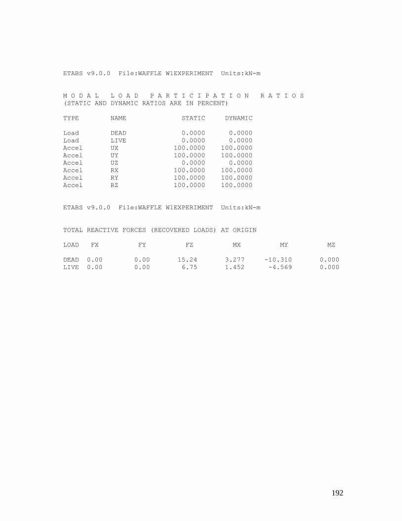
192
ETABS v9.0.0 File:WAFFLE W1EXPERIMENT Units:kN-m
M O D A L L O A D P A R T I C I P A T I O N R A T I O S
(STATIC AND DYNAMIC RATIOS ARE IN PERCENT)
TYPE NAME STATIC DYNAMIC
Load DEAD 0.0000 0.0000
Load LIVE 0.0000 0.0000
Accel UX 100.0000 100.0000
Accel UY 100.0000 100.0000
Accel UZ 0.0000 0.0000
Accel RX 100.0000 100.0000
Accel RY 100.0000 100.0000
Accel RZ 100.0000 100.0000
ETABS v9.0.0 File:WAFFLE W1EXPERIMENT Units:kN-m
TOTAL REACTIVE FORCES (RECOVERED LOADS) AT ORIGIN
LOAD FX FY FZ MX MY MZ
DEAD 0.00 0.00 15.24 3.277 -10.310 0.000
LIVE 0.00 0.00 6.75 1.452 -4.569 0.000

193
Appendix 34: Result of waffle W2 Experimental (ETABS)
ETABS v9.0.0 File:WAFFLE W2EXPERIMENT Units:kN-m
PROJECT INFORMATION
Company Name = eng
ETABS v9.0.0 File:WAFFLE W2EXPERIMENT Units:kN-m
S T O R Y D A T A
STORY SIMILAR TO HEIGHT ELEVATION
STORY1 None 0.750 0.750
BASE None 0.000
ETABS v9.0.0 File:WAFFLE W2EXPERIMENT Units:kN-m
S T A T I C L O A D C A S E S
STATIC CASE AUTO LAT SELF WT
CASE TYPE LOAD MULTIPLIER
DEAD DEAD N/A 0.1000
LIVE REDUCE LIVE N/A 0.0000
ETABS v9.0.0 File:WAFFLE W2EXPERIMENT Units:kN-m
M A S S S O U R C E D A T A
MASS LATERAL LUMP MASS
FROM MASS ONLY AT STORIES
Masses Yes Yes
ETABS v9.0.0 File:WAFFLE W2EXPERIMENT Units:kN-m
D I A P H R A G M M A S S D A T A
STORY DIAPHRAGM MASS-X MASS-Y MMI X-M Y-M
STORY1 D1 2.1975 2.1975 0.4053 0.454 0.150

194
ETABS v9.0.0 File:WAFFLE W2EXPERIMENT Units:kN-m
A S S E M B L E D P O I N T M A S S E S
STORY UX UY UZ RX RY RZ
STORY1 2.197480 2.197480 0.000000 0.000000 0.000000 0.405288
BASE 0.752728 0.752728 0.000000 0.000000 0.000000 0.000000
Totals 2.950208 2.950208 0.000000 0.000000 0.000000 0.405288
ETABS v9.0.0 File:WAFFLE W2EXPERIMENT Units:kN-m
C E N T E R S O F C U M U L A T I V E M A S S & C E N T E R
S O F R I G I D I T Y
STORY DIAPHRAGM /----------CENTRE OF MASS----------//--CENTRE OF
RIGIDITY--/
LEVEL NAME MASS ORDINATE-X ORDINATE-Y ORDINATE-X ORDINATE-Y
STORY1 D1 2.1975 0.454 0.150 0.474 0.150
ETABS v9.0.0 File:WAFFLE W2EXPERIMENT Units:kN-m
M O D A L P E R I O D S A N D F R E Q U E N C I E S
MODE PERIOD FREQUENCY CIRCULAR FREQ
NUMBER (TIME) (CYCLES/TIME) (RADIANS/TIME)
Mode 1 0.01283 77.94835 489.76390
Mode 2 0.00922 108.49457 681.69150
Mode 3 0.00892 112.12289 704.48889
ETABS v9.0.0 File:WAFFLE W2EXPERIMENT Units:kN-m
M O D A L P A R T I C I P A T I N G M A S S R A T I O S
MODE X-TRANS Y-TRANS Z-TRANS RX-ROTN RY-ROTN RZ-ROTN
NUMBER %MASS <SUM> %MASS <SUM> %MASS <SUM> %MASS <SUM>
%MASS <SUM> %MASS <SUM>
Mode 1 0.00 < 0> 99.82 <100> 0.00 < 0> 99.82
<100> 0.00 < 0> 0.16 < 0>
Mode 2 100.00 <100> 0.00 <100> 0.00 < 0> 0.00
<100> 100.00 <100> 0.00 < 0>
Mode 3 0.00 <100> 0.18 <100> 0.00 < 0> 0.18
<100> 0.00 <100> 99.84 <100>

195
ETABS v9.0.0 File:WAFFLE W2EXPERIMENT Units:kN-m
M O D A L L O A D P A R T I C I P A T I O N R A T I O S
(STATIC AND DYNAMIC RATIOS ARE IN PERCENT)
TYPE NAME STATIC DYNAMIC
Load DEAD 0.0683 0.0000
Load LIVE 0.0017 0.0000
Accel UX 100.0000 100.0000
Accel UY 100.0000 100.0000
Accel UZ 0.0000 0.0000
Accel RX 100.0000 100.0000
Accel RY 100.0000 100.0000
Accel RZ 104.3987 100.0000
ETABS v9.0.0 File:WAFFLE W2EXPERIMENT Units:kN-m
TOTAL REACTIVE FORCES (RECOVERED LOADS) AT ORIGIN
LOAD FX FY FZ MX MY MZ
DEAD 0.00 0.00 3.11 0.467 -1.401 0.000
LIVE 0.00 0.00 0.76 0.114 -0.399 0.000
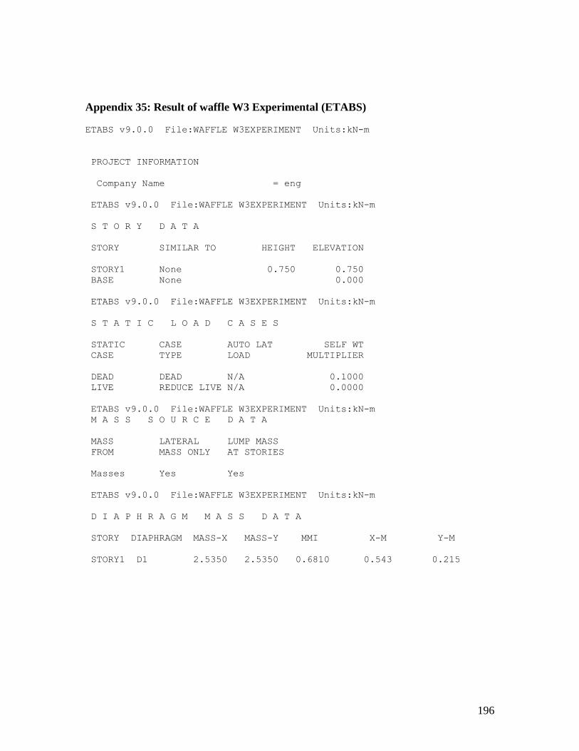
196
Appendix 35: Result of waffle W3 Experimental (ETABS)
ETABS v9.0.0 File:WAFFLE W3EXPERIMENT Units:kN-m
PROJECT INFORMATION
Company Name = eng
ETABS v9.0.0 File:WAFFLE W3EXPERIMENT Units:kN-m
S T O R Y D A T A
STORY SIMILAR TO HEIGHT ELEVATION
STORY1 None 0.750 0.750
BASE None 0.000
ETABS v9.0.0 File:WAFFLE W3EXPERIMENT Units:kN-m
S T A T I C L O A D C A S E S
STATIC CASE AUTO LAT SELF WT
CASE TYPE LOAD MULTIPLIER
DEAD DEAD N/A 0.1000
LIVE REDUCE LIVE N/A 0.0000
ETABS v9.0.0 File:WAFFLE W3EXPERIMENT Units:kN-m
M A S S S O U R C E D A T A
MASS LATERAL LUMP MASS
FROM MASS ONLY AT STORIES
Masses Yes Yes
ETABS v9.0.0 File:WAFFLE W3EXPERIMENT Units:kN-m
D I A P H R A G M M A S S D A T A
STORY DIAPHRAGM MASS-X MASS-Y MMI X-M Y-M
STORY1 D1 2.5350 2.5350 0.6810 0.543 0.215

197
ETABS v9.0.0 File:WAFFLE W3EXPERIMENT Units:kN-m
A S S E M B L E D P O I N T M A S S E S
STORY UX UY UZ RX RY RZ
STORY1 2.535048 2.535048 0.000000 0.000000 0.000000 0.680962
BASE 0.752728 0.752728 0.000000 0.000000 0.000000 0.000000
Totals 3.287776 3.287776 0.000000 0.000000 0.000000 0.680962
ETABS v9.0.0 File:WAFFLE W3EXPERIMENT Units:kN-m
C E N T E R S O F C U M U L A T I V E M A S S & C E N T E R
S O F R I G I D I T Y
STORY DIAPHRAGM /----------CENTRE OF MASS----------//--CENTRE OF
RIGIDITY--/
LEVEL NAME MASS ORDINATE-X ORDINATE-Y ORDINATE-X ORDINATE-Y
STORY1 D1 2.5350 0.543 0.215 0.542 0.215
ETABS v9.0.0 File:WAFFLE W3EXPERIMENT Units:kN-m
M O D A L P E R I O D S A N D F R E Q U E N C I E S
MODE PERIOD FREQUENCY CIRCULAR FREQ
NUMBER (TIME) (CYCLES/TIME) (RADIANS/TIME)
Mode 1 0.01145 87.32430 548.67473
Mode 2 0.00993 100.66678 632.50804
Mode 3 0.00892 112.09162 704.29241
ETABS v9.0.0 File:WAFFLE W3EXPERIMENT Units:kN-m
M O D A L P A R T I C I P A T I N G M A S S R A T I O S
MODE X-TRANS Y-TRANS Z-TRANS RX-ROTN RY-ROTN RZ-ROTN
NUMBER %MASS <SUM> %MASS <SUM> %MASS <SUM> %MASS
<SUM> %MASS <SUM> %MASS <SUM>
Mode 1 0.00 < 0> 100.00 <100> 0.00 < 0> 100.00 <100>
0.00 < 0> 0.00 < 0>
Mode 2 100.00 <100> 0.00 <100> 0.00 < 0> 0.00 <100>
100.00 <100> 0.00 < 0>
Mode 3 0.00 <100> 0.00 <100> 0.00 < 0> 0.00 <100>
0.00 <100> 100.00 <100>

198
ETABS v9.0.0 File:WAFFLE W3EXPERIMENT Units:kN-m
M O D A L L O A D P A R T I C I P A T I O N R A T I O S
(STATIC AND DYNAMIC RATIOS ARE IN PERCENT)
TYPE NAME STATIC DYNAMIC
Load DEAD 0.0000 0.0000
Load LIVE 0.0000 0.0000
Accel UX 100.0000 100.0000
Accel UY 100.0000 100.0000
Accel UZ 0.0000 0.0000
Accel RX 100.0000 100.0000
Accel RY 100.0000 100.0000
Accel RZ 100.0000 100.0000
ETABS v9.0.0 File:WAFFLE W3EXPERIMENT Units:kN-m
TOTAL REACTIVE FORCES (RECOVERED LOADS) AT ORIGIN
LOAD FX FY FZ MX MY MZ
DEAD 0.00 0.00 11.02 2.369 -5.978 0.000
LIVE 0.00 0.00 4.51 0.969 -2.445 0.000

199
Appendix 36: Result of waffle W4 Experimental (ETABS)
ETABS v9.0.0 File:WAFFLE W4EXPERIMENT Units:kN-m
PROJECT INFORMATION
Company Name = eng
ETABS v9.0.0 File:WAFFLE W4EXPERIMENT Units:kN-m
S T O R Y D A T A
STORY SIMILAR TO HEIGHT ELEVATION
STORY1 None 0.750 0.750
BASE None 0.000
ETABS v9.0.0 File:WAFFLE W4EXPERIMENT Units:kN-m
S T A T I C L O A D C A S E S
STATIC CASE AUTO LAT SELF WT
CASE TYPE LOAD MULTIPLIER
DEAD DEAD N/A 0.1000
LIVE REDUCE LIVE N/A 0.0000
ETABS v9.0.0 File:WAFFLE W4EXPERIMENT Units:kN-m
M A S S S O U R C E D A T A
MASS LATERAL LUMP MASS
FROM MASS ONLY AT STORIES
Masses Yes Yes
ETABS v9.0.0 File:WAFFLE W4EXPERIMENT Units:kN-m
D I A P H R A G M M A S S D A T A
STORY DIAPHRAGM MASS-X MASS-Y MMI X-M Y-M
STORY1 D1 1.6154 1.6154 0.1075 0.204 0.182

200
ETABS v9.0.0 File:WAFFLE W4EXPERIMENT Units:kN-m
A S S E M B L E D P O I N T M A S S E S
STORY UX UY UZ RX RY RZ
STORY1 1.615446 1.615446 0.000000 0.000000 0.000000 0.107542
BASE 0.752728 0.752728 0.000000 0.000000 0.000000 0.000000
Totals 2.368174 2.368174 0.000000 0.000000 0.000000 0.107542
ETABS v9.0.0 File:WAFFLE W4EXPERIMENT Units:kN-m
C E N T E R S O F C U M U L A T I V E M A S S & C E N T E R S
O F R I G I D I T Y
STORY DIAPHRAGM /----------CENTRE OF MASS----------//--CENTRE OF
RIGIDITY--/
LEVEL NAME MASS ORDINATE-X ORDINATE-Y ORDINATE-X ORDINATE-Y
STORY1 D1 1.6154 0.204 0.182 0.204 0.182
ETABS v9.0.0 File:WAFFLE W4EXPERIMENT Units:kN-m
M O D A L P E R I O D S A N D F R E Q U E N C I E S
MODE PERIOD FREQUENCY CIRCULAR FREQ
NUMBER (TIME) (CYCLES/TIME) (RADIANS/TIME)
Mode 1 0.00973 102.72929 645.46719
Mode 2 0.00934 107.06637 672.71782
Mode 3 0.00686 145.82088 916.21964
ETABS v9.0.0 File:WAFFLE W4EXPERIMENT Units:kN-m
M O D A L P A R T I C I P A T I N G M A S S R A T I O S
MODE X-TRANS Y-TRANS Z-TRANS RX-ROTN RY-ROTN RZ-ROTN
NUMBER %MASS <SUM> %MASS <SUM> %MASS <SUM> %MASS <SUM>
%MASS <SUM> %MASS <SUM>
Mode 1 0.00 < 0> 100.00 <100> 0.00 < 0> 100.00
<100> 0.00 < 0> 0.00 < 0>
Mode 2 100.00 <100> 0.00 <100> 0.00 < 0> 0.00
<100> 100.00 <100> 0.00 < 0>
Mode 3 0.00 <100> 0.00 <100> 0.00 < 0> 0.00
<100> 0.00 <100> 100.00 <100>

201
ETABS v9.0.0 File:WAFFLE W4EXPERIMENT Units:kN-m
M O D A L L O A D P A R T I C I P A T I O N R A T I O S
(STATIC AND DYNAMIC RATIOS ARE IN PERCENT)
TYPE NAME STATIC DYNAMIC
Load DEAD 0.0000 0.0000
Load LIVE 0.0000 0.0000
Accel UX 100.0000 100.0000
Accel UY 100.0000 100.0000
Accel UZ 0.0000 0.0000
Accel RX 100.0000 100.0000
Accel RY 100.0000 100.0000
Accel RZ 100.0000 100.0000
ETABS v9.0.0 File:WAFFLE W4EXPERIMENT Units:kN-m
TOTAL REACTIVE FORCES (RECOVERED LOADS) AT ORIGIN
LOAD FX FY FZ MX MY MZ
DEAD 0.00 0.00 2.45 0.446 -0.498 0.000
LIVE 0.00 0.00 1.58 0.287 -0.321 0.000

202
Appendix 37: Result of waffle W5 Experimental (ETABS)
ETABS v9.0.0 File:WAFFLE W5EXPERIMENT Units:kN-m
PROJECT INFORMATION
Company Name = eng
ETABS v9.0.0 File:WAFFLE W5EXPERIMENT Units:kN-m
S T O R Y D A T A
STORY SIMILAR TO HEIGHT ELEVATION
STORY1 None 0.750 0.750
BASE None 0.000
ETABS v9.0.0 File:WAFFLE W5EXPERIMENT Units:kN-m
S T A T I C L O A D C A S E S
STATIC CASE AUTO LAT SELF WT
CASE TYPE LOAD MULTIPLIER
DEAD DEAD N/A 0.1000
LIVE REDUCE LIVE N/A 0.0000
ETABS v9.0.0 File:WAFFLE W5EXPERIMENT Units:kN-m
M A S S S O U R C E D A T A
MASS LATERAL LUMP MASS
FROM MASS ONLY AT STORIES
Masses Yes Yes
ETABS v9.0.0 File:WAFFLE W5EXPERIMENT Units:kN-m
D I A P H R A G M M A S S D A T A
STORY DIAPHRAGM MASS-X MASS-Y MMI X-M Y-M
STORY1 D1 2.2570 2.2570 0.8492 0.668 0.147
ETABS v9.0.0 File:WAFFLE W5EXPERIMENT Units:kN-m
A S S E M B L E D P O I N T M A S S E S
STORY UX UY UZ RX RY RZ
STORY1 2.749433 2.749433 0.000000 0.000000 0.000000 0.849182
BASE 0.752728 0.752728 0.000000 0.000000 0.000000 0.000000
Totals 3.502160 3.502160 0.000000 0.000000 0.000000 0.849182
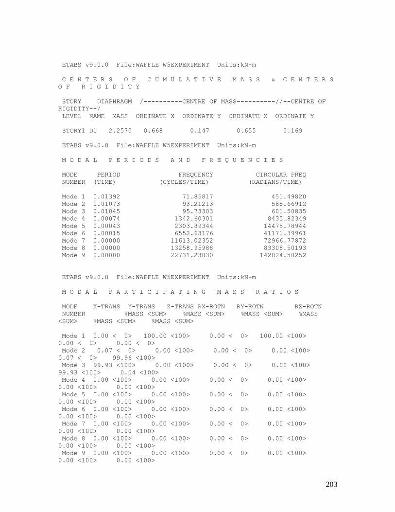
203
ETABS v9.0.0 File:WAFFLE W5EXPERIMENT Units:kN-m
C E N T E R S O F C U M U L A T I V E M A S S & C E N T E R S
O F R I G I D I T Y
STORY DIAPHRAGM /----------CENTRE OF MASS----------//--CENTRE OF
RIGIDITY--/
LEVEL NAME MASS ORDINATE-X ORDINATE-Y ORDINATE-X ORDINATE-Y
STORY1 D1 2.2570 0.668 0.147 0.655 0.169
ETABS v9.0.0 File:WAFFLE W5EXPERIMENT Units:kN-m
M O D A L P E R I O D S A N D F R E Q U E N C I E S
MODE PERIOD FREQUENCY CIRCULAR FREQ
NUMBER (TIME) (CYCLES/TIME) (RADIANS/TIME)
Mode 1 0.01392 71.85817 451.49820
Mode 2 0.01073 93.21213 585.66912
Mode 3 0.01045 95.73303 601.50835
Mode 4 0.00074 1342.60301 8435.82349
Mode 5 0.00043 2303.89344 14475.78944
Mode 6 0.00015 6552.63176 41171.39961
Mode 7 0.00000 11613.02352 72966.77872
Mode 8 0.00000 13258.95988 83308.50193
Mode 9 0.00000 22731.23830 142824.58252
ETABS v9.0.0 File:WAFFLE W5EXPERIMENT Units:kN-m
M O D A L P A R T I C I P A T I N G M A S S R A T I O S
MODE X-TRANS Y-TRANS Z-TRANS RX-ROTN RY-ROTN RZ-ROTN
NUMBER %MASS <SUM> %MASS <SUM> %MASS <SUM> %MASS
<SUM> %MASS <SUM> %MASS <SUM>
Mode 1 0.00 < 0> 100.00 <100> 0.00 < 0> 100.00 <100>
0.00 < 0> 0.00 < 0>
Mode 2 0.07 < 0> 0.00 <100> 0.00 < 0> 0.00 <100>
0.07 < 0> 99.96 <100>
Mode 3 99.93 <100> 0.00 <100> 0.00 < 0> 0.00 <100>
99.93 <100> 0.04 <100>
Mode 4 0.00 <100> 0.00 <100> 0.00 < 0> 0.00 <100>
0.00 <100> 0.00 <100>
Mode 5 0.00 <100> 0.00 <100> 0.00 < 0> 0.00 <100>
0.00 <100> 0.00 <100>
Mode 6 0.00 <100> 0.00 <100> 0.00 < 0> 0.00 <100>
0.00 <100> 0.00 <100>
Mode 7 0.00 <100> 0.00 <100> 0.00 < 0> 0.00 <100>
0.00 <100> 0.00 <100>
Mode 8 0.00 <100> 0.00 <100> 0.00 < 0> 0.00 <100>
0.00 <100> 0.00 <100>
Mode 9 0.00 <100> 0.00 <100> 0.00 < 0> 0.00 <100>
0.00 <100> 0.00 <100>
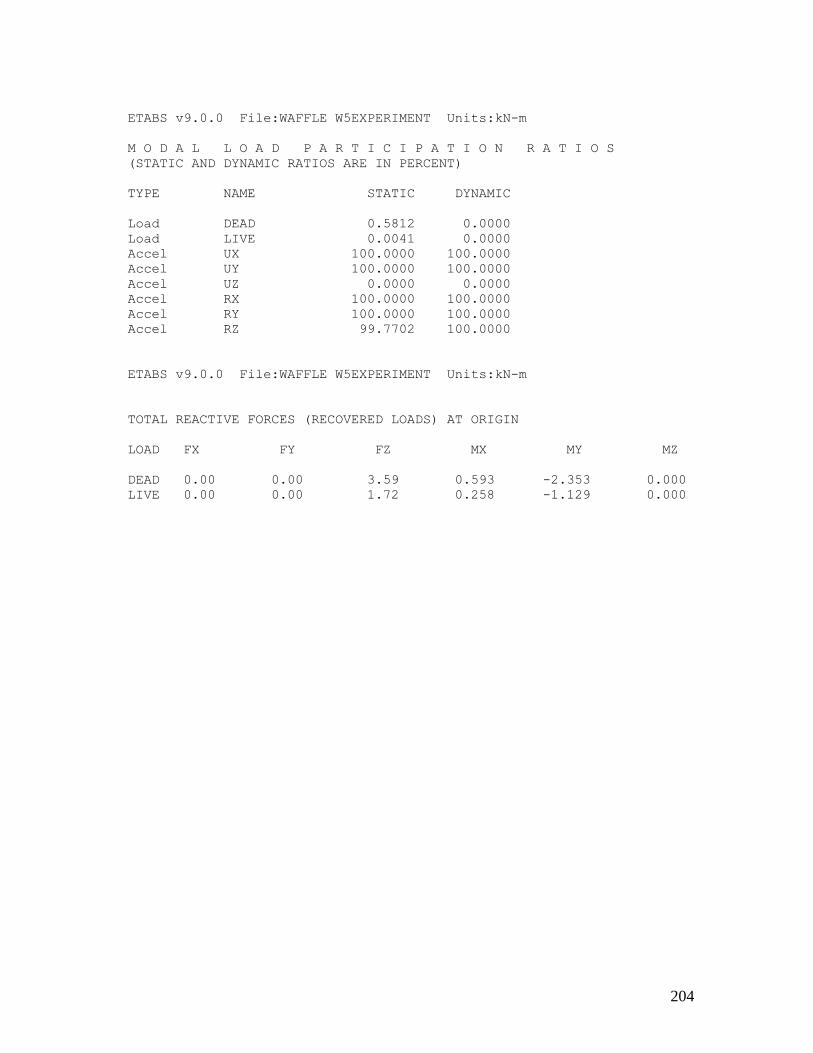
204
ETABS v9.0.0 File:WAFFLE W5EXPERIMENT Units:kN-m
M O D A L L O A D P A R T I C I P A T I O N R A T I O S
(STATIC AND DYNAMIC RATIOS ARE IN PERCENT)
TYPE NAME STATIC DYNAMIC
Load DEAD 0.5812 0.0000
Load LIVE 0.0041 0.0000
Accel UX 100.0000 100.0000
Accel UY 100.0000 100.0000
Accel UZ 0.0000 0.0000
Accel RX 100.0000 100.0000
Accel RY 100.0000 100.0000
Accel RZ 99.7702 100.0000
ETABS v9.0.0 File:WAFFLE W5EXPERIMENT Units:kN-m
TOTAL REACTIVE FORCES (RECOVERED LOADS) AT ORIGIN
LOAD FX FY FZ MX MY MZ
DEAD 0.00 0.00 3.59 0.593 -2.353 0.000
LIVE 0.00 0.00 1.72 0.258 -1.129 0.000

205
Appendix 38: Result of waffle W6 Experimental (ETABS)
ETABS v9.0.0 File:WAFFLE W6EXPERIMENT Units:kN-m
PROJECT INFORMATION
Company Name = eng
ETABS v9.0.0 File:WAFFLE W6EXPERIMENT Units:kN-m
S T O R Y D A T A
STORY SIMILAR TO HEIGHT ELEVATION
STORY1 None 0.750 0.750
BASE None 0.000
ETABS v9.0.0 File:WAFFLE W6EXPERIMENT Units:kN-m
S T A T I C L O A D C A S E S
STATIC CASE AUTO LAT SELF WT
CASE TYPE LOAD MULTIPLIER
DEAD DEAD N/A 0.1000
LIVE REDUCE LIVE N/A 0.0000
ETABS v9.0.0 File:WAFFLE W6EXPERIMENT Units:kN-m
M A S S S O U R C E D A T A
MASS LATERAL LUMP MASS
FROM MASS ONLY AT STORIES
Masses Yes Yes
ETABS v9.0.0 File:WAFFLE W6EXPERIMENT Units:kN-m
D I A P H R A G M M A S S D A T A
STORY DIAPHRAGM MASS-X MASS-Y MMI X-M Y-M
STORY1 D1 1.6898 1.6898 0.3085 0.430 0.180
ETABS v9.0.0 File:WAFFLE W6EXPERIMENT Units:kN-m
A S S E M B L E D P O I N T M A S S E S
STORY UX UY UZ RX RY RZ
STORY1 1.689796 1.689796 0.000000 0.000000 0.000000 0.308515
BASE 0.752728 0.752728 0.000000 0.000000 0.000000 0.000000

206
Totals 2.442524 2.442524 0.000000 0.000000 0.000000 0.308515
ETABS v9.0.0 File:WAFFLE W6EXPERIMENT Units:kN-m
C E N T E R S O F C U M U L A T I V E M A S S & C E N T E R S
O F R I G I D I T Y
STORY DIAPHRAGM /----------CENTRE OF MASS----------//--CENTRE OF
RIGIDITY--/
LEVEL NAME MASS ORDINATE-X ORDINATE-Y ORDINATE-X ORDINATE-Y
STORY1 D1 1.6898 0.430 0.180 0.430 0.180
ETABS v9.0.0 File:WAFFLE W6EXPERIMENT Units:kN-m
M O D A L P E R I O D S A N D F R E Q U E N C I E S
MODE PERIOD FREQUENCY CIRCULAR FREQ
NUMBER (TIME) (CYCLES/TIME) (RADIANS/TIME)
Mode 1 0.01037 96.47473 606.16863
Mode 2 0.00834 119.94595 753.64261
Mode 3 0.00780 128.27638 805.98424
ETABS v9.0.0 File:WAFFLE W6EXPERIMENT Units:kN-m
M O D A L P A R T I C I P A T I N G M A S S R A T I O S
MODE X-TRANS Y-TRANS Z-TRANS RX-ROTN RY-ROTN RZ-ROTN
NUMBER %MASS <SUM> %MASS <SUM> %MASS <SUM> %MASS
<SUM> %MASS <SUM> %MASS <SUM>
Mode 1 0.00 < 0> 100.00 <100> 0.00 < 0> 100.00 <100>
0.00 < 0> 0.00 < 0>
Mode 2 100.00 <100> 0.00 <100> 0.00 < 0> 0.00 <100>
100.00 <100> 0.00 < 0>
Mode 3 0.00 <100> 0.00 <100> 0.00 < 0> 0.00 <100>
0.00 <100> 100.00 <100>
ETABS v9.0.0 File:WAFFLE W6EXPERIMENT Units:kN-m
M O D A L L O A D P A R T I C I P A T I O N R A T I O S
(STATIC AND DYNAMIC RATIOS ARE IN PERCENT)
TYPE NAME STATIC DYNAMIC
Load DEAD 0.0000 0.0000
Load LIVE 0.0000 0.0000
Accel UX 100.0000 100.0000
Accel UY 100.0000 100.0000
Accel UZ 0.0000 0.0000
Accel RX 100.0000 100.0000
Accel RY 100.0000 100.0000
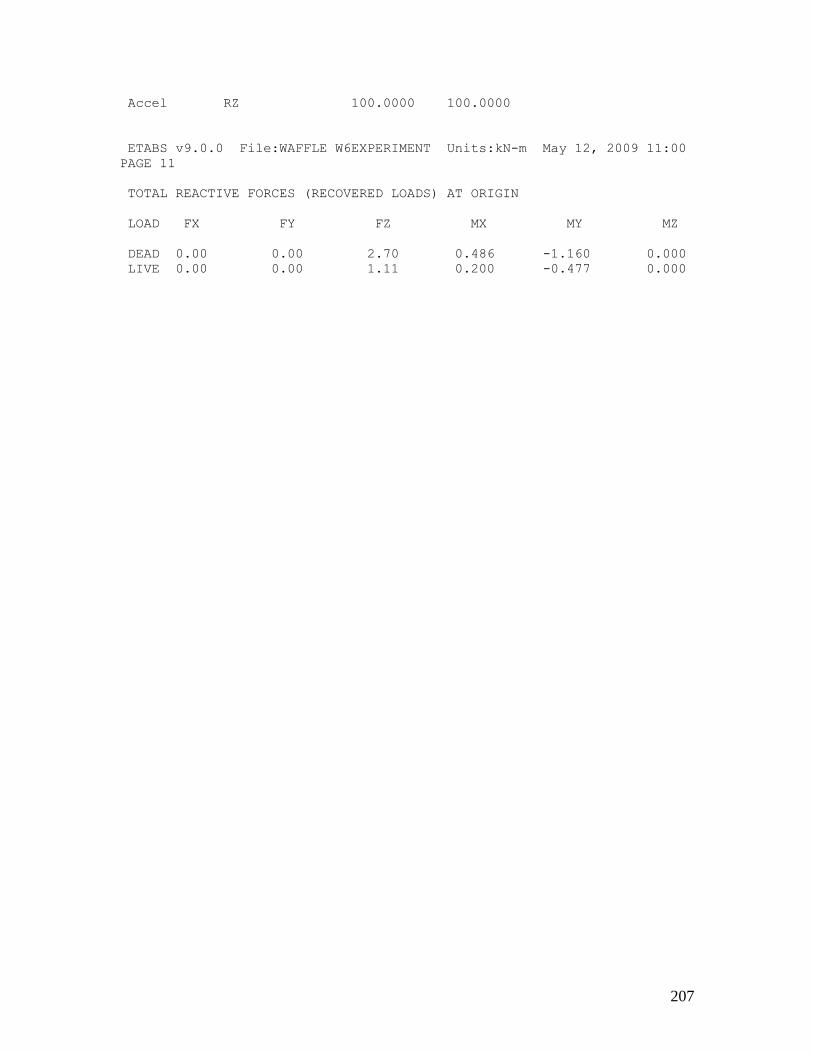
207
Accel RZ 100.0000 100.0000
ETABS v9.0.0 File:WAFFLE W6EXPERIMENT Units:kN-m May 12, 2009 11:00
PAGE 11
TOTAL REACTIVE FORCES (RECOVERED LOADS) AT ORIGIN
LOAD FX FY FZ MX MY MZ
DEAD 0.00 0.00 2.70 0.486 -1.160 0.000
LIVE 0.00 0.00 1.11 0.200 -0.477 0.000

208
Appendix 39: Test results for panel W1
Load (kN) Deflections (mm) Crack width
2 0.10 -
4 0.15 -
6 0.23 -
8 0.31 -
10 0.40 -
12 0.49 -
14 0.80 -
16 0.99 -
18 1.19 0.60
Appendix 40 : Test results for panel W2
Load (kN) Deflections (mm) Crack width (mm)
1 0.34 -
2 0.71 -
3 0.89 -
4 1.34 -
5 1.51 -
6 1.70 -
7 1.90 -
8 2.70 -
9 3.64 0.35

209
Appendix 41 : Test results for panel W3
Load (kN) Deflection (mm) Crack width (mm)
2 0 -
4 1.11 -
6 1.79 -
8 2.45 -
10 2.99 -
12 3.90 0.34
Appendix 42: Test results for panel W4
Load (kN) Deflection (mm) Crack width (mm)
1 1.45 -
2 3.31 -
3 4.69 -
4 5.90 -
5 6.16 -
6 6.60 0.25
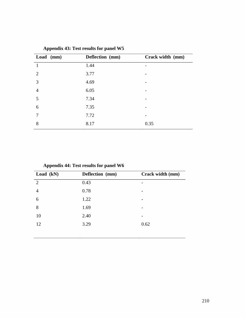
210
Appendix 43: Test results for panel W5
Load (mm) Deflection (mm) Crack width (mm)
1 1.44 -
2 3.77 -
3 4.69 -
4 6.05 -
5 7.34 -
6 7.35 -
7 7.72 -
8 8.17 0.35
Appendix 44: Test results for panel W6
Load (kN) Deflection (mm) Crack width (mm)
2 0.43 -
4 0.78 -
6 1.22 -
8 1.69 -
10 2.40 -
12 3.29 0.62
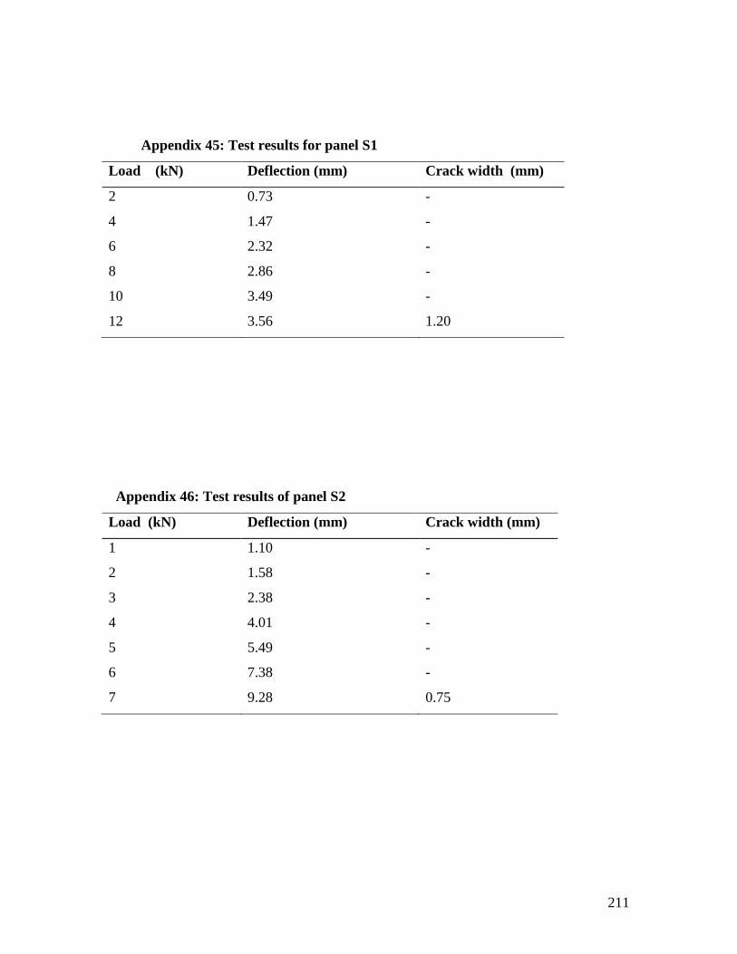
211
Appendix 45: Test results for panel S1
Load (kN) Deflection (mm) Crack width (mm)
2 0.73 -
4 1.47 -
6 2.32 -
8 2.86 -
10 3.49 -
12 3.56 1.20
Appendix 46: Test results of panel S2
Load (kN) Deflection (mm) Crack width (mm)
1 1.10 -
2 1.58 -
3 2.38 -
4 4.01 -
5 5.49 -
6 7.38 -
7 9.28 0.75
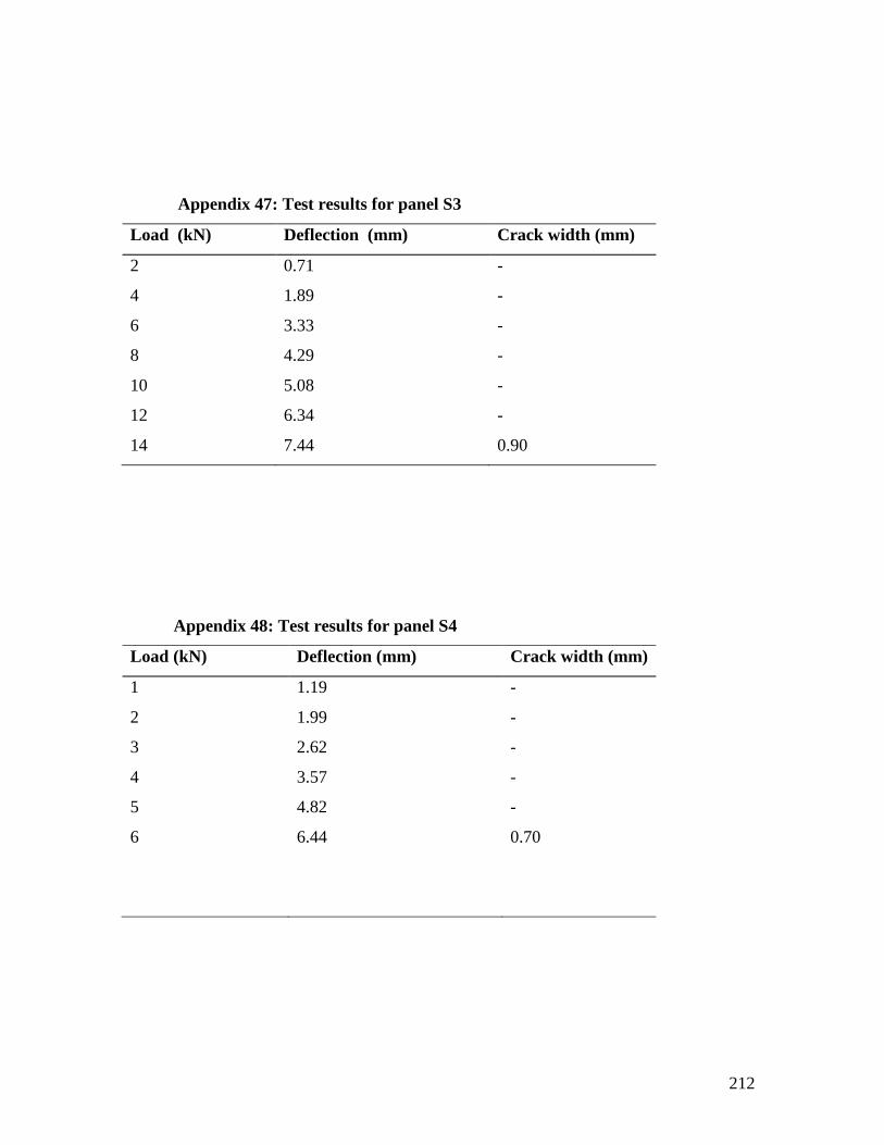
212
Appendix 47: Test results for panel S3
Load (kN) Deflection (mm) Crack width (mm)
2 0.71 -
4 1.89 -
6 3.33 -
8 4.29 -
10 5.08 -
12
14
6.34
7.44
-
0.90
Appendix 48: Test results for panel S4
Load (kN) Deflection (mm) Crack width (mm)
1 1.19 -
2 1.99 -
3 2.62 -
4 3.57 -
5 4.82 -
6 6.44 0.70

213
Appendix 49: Test results for panel S5
Load (kN) Deflection (mm) Crack width (mm)
1 2.14 -
2 6.18 -
3 7.52 -
4 9.30 -
5 11.75 -
6 12.18 1.10
Appendix 50: Test results for panel S6
Load (kN) Deflection (mm) Crack width (mm)
2 0.14 -
4 0.91 -
6 1.79 -
8 2.82 -
10 3.89 1.30

214
Appendix 51: Analysis of variance table for W1 and S1
Source
of variation
Degree
of freedom
Sum of square Mean square Variance ratio
F
Specimens 1 12.83 12.83 21.93**
Error 13 7.61 0.585
Total 14 20.44
F** >P0.05 significant
P0.05 = 4.67 ( F tabulated)
Appendix 52: Analysis of variance table for W2 and S2
Source
of variation
Degree
of freedom
Sum of square Mean square Variance ratio
F
Specimens 1 34.83 34.83 7.01**
Error 14 69.60 4.97
Total 15 104.43
F**>P0.05 significant
P0.05 = 4.60 (F tabulated)
Appendix 53: Analysis of variance table for W3 and S3
Source
of variation
Degree
of freedom
Sum of square Mean square Variance ratio
F
Specimens 1 14.46 14.46 3.637*
Error 11 43.74 3.98
Total 12 58.20
F* < P0.05 no significance
P0.05= 4.96 (F tabulated)

215
Appendix 54: Analysis of variance table for W4 and S4
Source
of variation
Degree
of freedom
Sum of square Mean square Variance ratio
F
Specimens 1 4.30 4.30 0.591*
Error 14 101.96 7.28
Total 15 106.26
F* < P0.05 no significance
P0.05= 4.60 (F tabulated)
Appendix 55: Analysis of variance table for W5 and S5
Source
of variation
Degree
of freedom
Sum of square Mean square Variance ratio
F
Specimens 1 18.94 18.94 2.076*
Error 12 109.42 9.12
Total 13 128.36
F* < P0.05 no significance
P0.05= 4.75 (F tabulated)
Appendix 56: Analysis of variance table for W6 and S6
Source
of variation
Degree
of freedom
Sum of square Mean square Variance ratio
F
Specimens 1 0.00 0.00 0.000*
Error 10 61.532 6.153
Total 11 61.532
F*< P0.05 no significance
P0.05= 4.96 (F tabulated)
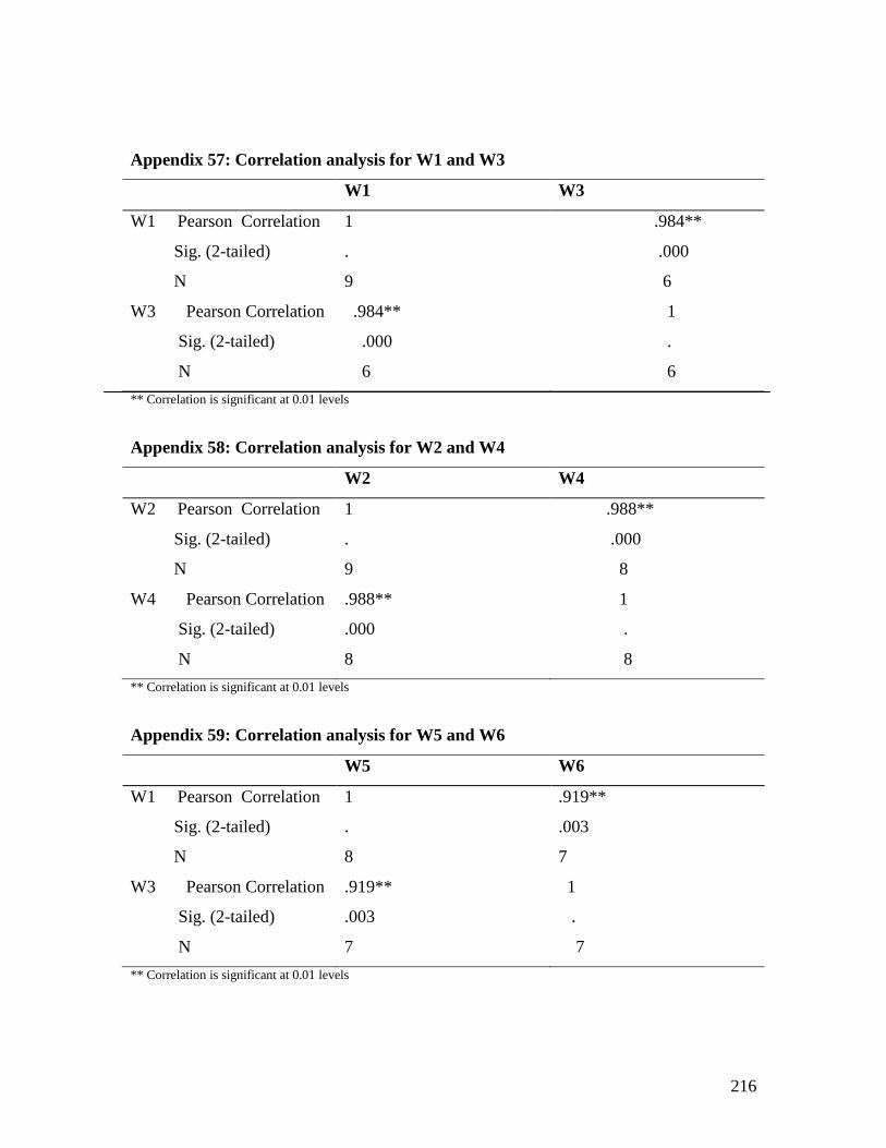
216
Appendix 57: Correlation analysis for W1 and W3
W1 W3
W1 Pearson Correlation
Sig. (2-tailed)
N
1
.
9
.984**
.000
6
W3 Pearson Correlation
Sig. (2-tailed)
N
.984**
.000
6
1
.
6
** Correlation is significant at 0.01 levels
Appendix 58: Correlation analysis for W2 and W4
W2 W4
W2 Pearson Correlation
Sig. (2-tailed)
N
1
.
9
.988**
.000
8
W4 Pearson Correlation
Sig. (2-tailed)
N
.988**
.000
8
1
.
8
** Correlation is significant at 0.01 levels
Appendix 59: Correlation analysis for W5 and W6
W5 W6
W1 Pearson Correlation
Sig. (2-tailed)
N
1
.
8
.919**
.003
7
W3 Pearson Correlation
Sig. (2-tailed)
N
.919**
.003
7
1
.
7
** Correlation is significant at 0.01 levels

217
Appendix 60: Correlation analysis for S1 and S3
S1 S3
W1 Pearson Correlation
Sig. (2-tailed)
N
1
.
6
.983**
.000
6
W3 Pearson Correlation
Sig. (2-tailed)
N
.983**
.000
6
1
.
6
** Correlation is significant at 0.01 levels
Appendix 61: Correlation analysis for S2 and S4
S2 S4
W1 Pearson Correlation
Sig. (2-tailed)
N
1
.
7
.997**
.000
7
W3 Pearson Correlation
Sig. (2-tailed)
N
.997**
.000
7
1
.000
8
** Correlation is significant at 0.01 levels
Appendix 62: Correlation analysis for S5 and S6
S5 S6
W1 Pearson Correlation
Sig. (2-tailed)
N
1
.
6
.974**
.005
5
W3 Pearson Correlation
Sig. (2-tailed)
N
.974**
.005
5
1
.
5
** Correlation is significant at 0.01 levels

218
Appendix 63: Estimation of flexural crack width at service for Slab S1
Modulus of elasticity of steel Es = 200 kN/mm2.
Calculate neutral axis position and steel stress.
Instantaneous modulus of elasticity = 20 kN/mm2
Ec = 20/2 = 10 kN/mm2
The neutral axis position is giving by
02
1 2 dAE
ExA
E
Ebx s
s
ss
c
s
In this case As = area of distribution bars in the slab = 377mm2
Effective depth, d = 40 – (5+3) = 32 mm
Thus 03237710
200377
10
2001000
2
1 2 xx
71.152
48341515 2
x
The neutral axis X = 15.71 mm
The stress in the reinforcement at the crack section,
fs = sAxd
M
3/ =
377)8.432(
10684.3 6
= 359 N/mm
2
ε1 = s
s
E
f
xd
y.
= 6
310101
10200
359.
7.17
yy
y is the distance from the neutral axis to the bottom of the slab = 25.7mm
ε1 = 25.7 x 101 x 10-6
= 2.58 x 10⁻³
εm = the average concrete strain,

219
33
1 10529.210)7.173772003
7.25407.2540100031.3(
3
'
xdAE
xaxhb
ss
tm
mm
xh
ca
aw
cr
mcr 035.0
3.14
507.421
10529.207.43
21
3 3
min
max
The estimated maximum crack width at service = 0.035 mm.
Appendix 64: Analysis of variance table of crack width for Waffle and Solid slabs
Source
of variation
Degree
of freedom
Sum of square Mean square Variance ratio
F
Specimens 1 0.770 0.770 15.46*
Error 10 0.498 0.049
Total 11 1.268
F* > P0.05 there is significance difference
P0.05= 4.96 (F tabulated)