ANALYSIS OF PILED RAFT FOUNDATION USING MIDAS GTS NX · Generally foundations are of two types,...
9
International Research Journal of Engineering and Technology (IRJET) e-ISSN: 2395-0056 Volume: 06 Issue: 05 | May 2019 www.irjet.net p-ISSN: 2395-0072 © 2019, IRJET | Impact Factor value: 7.211 | ISO 9001:2008 Certified Journal | Page 5491 ANALYSIS OF PILED RAFT FOUNDATION USING MIDAS GTS NX Sonia Saini* 1 , Er. Tripti Goyal 2 * 1 M. Tech Student, Modern Institute of Engineering & Technology, Mohri (Haryana) 2 Head of Department, Civil Engineering, Modern Institute of Engineering & Technology, Mohri (Haryana) -----------------------------------------------------------------------------***----------------------------------------------------------------------------- Abstract: - Foundation is the structural element which connects the superstructure to the ground beneath it. Generally foundations are of two types, first is shallow foundation such as a raft and the second is deep foundation such as a pile. Traditionally it is a common practice in foundation design to consider first the use of a shallow foundation system such as a raft and if the shallow foundation was not adequate, a fully piled foundation taking the entire design load was designed. Rafts cover the entire area of the structure and transmit the load to the underlying soil. They do not require any deep excavations for their construction. Pile foundations require deep excavations and transmit the load to hard strata at deeper depths. In some cases the raft is capable of taking the structural loads efficiently but can’t control the settlements or differential settlements. In such a condition rather than increasing the thickness of the raft another alternative called the piled-raft foundation system can be adopted. The piles and raft act as a single unit in a pile-raft system. From the laboratory experiments and 3D simulation of piled raft in Midas GTS NX, the reduction in settlements with increase in diameter becomes insignificant after a certain range of diameter. The variation of pile length shows more influence on the settlements than the variation of pile diameter. The use of piled raft as an alternate for raft foundation results in around 30% decrease in raft thickness, along with 20% decrease in the settlements when the raft thickness was reduced to 50cm from 70cm.In order to bring down the settlement of 78.7mm in 70cm raft foundation, the first alternative of using a piled raft of 50cm thickness resulted in the decrease of settlement by about 20%. The introduction of piles irrespective of the raft thickness results in considerable decrease in the foundation settlements. Use of piled raft can be used to reduce the settlements of the raft as well as the material resources by reduction in the raft thickness. Midas GTS NX proves to be efficient software in the analysis of piled raft foundation with a user friendly interface and can aid in the analysis of complex problems. Key Words: Numerical modeling, piled raft, full-scale field tests, Midas GTS NX 1. INTRODUCTION Foundation is the structural element which connects the superstructure to the ground beneath it. Generally foundations are of two types, first is shallow foundation such as a raft and the second is deep foundation such as a pile. Traditionally it is a common practice in foundation design to consider first the use of a shallow foundation system such as a raft and if the shallow foundation was not adequate, a fully piled foundation taking the entire design load was designed. Rafts cover the entire area of the structure and transmit the load to the underlying soil. They do not require any deep excavations for their construction. Pile foundations require deep excavations and transmit the load to hard strata at deeper depths. In some cases the raft is capable of taking the structural loads efficiently but can’t control the settlements or differential settlements. In such a condition rather than increasing the thickness of the raft another alternative called the piled-raft foundation system can be adopted. The piles and raft act as a single unit in a pile-raft system. In a piled raft system the raft takes most of the load while the pile controls the settlement or differential settlement. The numerical calculations were performed using commercial software Midas GTS NX and concentrated on some specific aspects of numerical modeling applied to deep foundations, especially the influence of the soil constitutive model and the pile-soil interface elements on overall settlements. Midas GTS NX is a FEM based modeling software. It includes CAD based 2D and 3D commands for modeling. GTS NX analyses foundation stability subjected to lateral pressure and differential settlements. 2. OBJECTIVES:- 1. To evaluate the engineering properties of soil. 2. To study the effect on displacements of raft with the introduction of piles. 3. To study the piled raft interactions with variations in thickness of raft. 4. To study the piled raft interactions with variation in length and diameter of piles. 3. EXPERIMENTAL INVESTIGATION:- Three samples of soil at different elevations have been collected from study area. To analysis the piled raft foundations in Midas GTS NX, the foremost requirement is to determine the basic soil engineering properties of various soil types of that area. A series of test has been
Transcript of ANALYSIS OF PILED RAFT FOUNDATION USING MIDAS GTS NX · Generally foundations are of two types,...

International Research Journal of Engineering and Technology (IRJET) e-ISSN: 2395-0056
Volume: 06 Issue: 05 | May 2019 www.irjet.net p-ISSN: 2395-0072
© 2019, IRJET | Impact Factor value: 7.211 | ISO 9001:2008 Certified Journal | Page 5491
ANALYSIS OF PILED RAFT FOUNDATION USING MIDAS GTS NX
Sonia Saini*1, Er. Tripti Goyal2
*1 M. Tech Student, Modern Institute of Engineering & Technology, Mohri (Haryana) 2Head of Department, Civil Engineering, Modern Institute of Engineering & Technology, Mohri (Haryana)
-----------------------------------------------------------------------------***----------------------------------------------------------------------------- Abstract: - Foundation is the structural element which connects the superstructure to the ground beneath it. Generally foundations are of two types, first is shallow foundation such as a raft and the second is deep foundation such as a pile. Traditionally it is a common practice in foundation design to consider first the use of a shallow foundation system such as a raft and if the shallow foundation was not adequate, a fully piled foundation taking the entire design load was designed. Rafts cover the entire area of the structure and transmit the load to the underlying soil. They do not require any deep excavations for their construction. Pile foundations require deep excavations and transmit the load to hard strata at deeper depths. In some cases the raft is capable of taking the structural loads efficiently but can’t control the settlements or differential settlements. In such a condition rather than increasing the thickness of the raft another alternative called the piled-raft foundation system can be adopted. The piles and raft act as a single unit in a pile-raft system. From the laboratory experiments and 3D simulation of piled raft in Midas GTS NX, the reduction in settlements with increase in diameter becomes insignificant after a certain range of diameter. The variation of pile length shows more influence on the settlements than the
variation of pile diameter. The use of piled raft as an alternate for raft foundation results in around 30% decrease in raft thickness, along with 20% decrease in the settlements when the raft thickness was reduced to 50cm from 70cm.In order to bring down the settlement of 78.7mm in 70cm raft foundation, the first alternative of using a piled raft of 50cm thickness resulted in the decrease of settlement by about 20%. The introduction of piles irrespective of the raft thickness results in considerable decrease in the foundation settlements. Use of piled raft can be used to reduce the settlements of the raft as well as the material resources by reduction in the raft thickness. Midas GTS NX proves to be efficient software in the analysis of piled raft foundation with a user friendly interface and can aid in the analysis of complex problems. Key Words: Numerical modeling, piled raft, full-scale field tests, Midas GTS NX 1. INTRODUCTION Foundation is the structural element which connects the superstructure to the ground beneath it. Generally
foundations are of two types, first is shallow foundation such as a raft and the second is deep foundation such as a pile. Traditionally it is a common practice in foundation design to consider first the use of a shallow foundation system such as a raft and if the shallow foundation was not adequate, a fully piled foundation taking the entire design load was designed. Rafts cover the entire area of the structure and transmit the load to the underlying soil. They do not require any deep excavations for their construction. Pile foundations require deep excavations and transmit the load to hard strata at deeper depths. In some cases the raft is capable of taking the structural loads efficiently but can’t control the settlements or differential settlements. In such a condition rather than increasing the thickness of the raft another alternative called the piled-raft foundation system can be adopted. The piles and raft act as a single unit in a pile-raft system. In a piled raft system the raft takes most of the load while the pile controls the settlement or differential settlement. The numerical calculations were performed using commercial software Midas GTS NX and concentrated on some specific aspects of numerical modeling applied to deep foundations, especially the influence of the soil constitutive model and the pile-soil interface elements on overall settlements. Midas GTS NX is a FEM based modeling software. It
includes CAD based 2D and 3D commands for modeling. GTS NX analyses foundation stability subjected to lateral pressure and differential settlements. 2. OBJECTIVES:- 1. To evaluate the engineering properties of soil. 2. To study the effect on displacements of raft with the introduction of piles. 3. To study the piled raft interactions with variations in thickness of raft. 4. To study the piled raft interactions with variation in
length and diameter of piles. 3. EXPERIMENTAL INVESTIGATION:-
Three samples of soil at different elevations have been collected from study area. To analysis the piled raft foundations in Midas GTS NX, the foremost requirement is to determine the basic soil engineering properties of various soil types of that area. A series of test has been

International Research Journal of Engineering and Technology (IRJET) e-ISSN: 2395-0056
Volume: 06 Issue: 05 | May 2019 www.irjet.net p-ISSN: 2395-0072
© 2019, IRJET | Impact Factor value: 7.211 | ISO 9001:2008 Certified Journal | Page 5492
conducted to determine some pre-requisite properties of soil.
Determination of In-situ density, moisture content and dry density of various soil samples.
a) In-situ density: - The in-situ density is defined as the bulk density of soil measured at its actual depth. By conducting this test, it is possible to determine the field density of the soil. The moisture content is likely to vary from time and hence the field density also.
Table1:- calculation of In-situ density
S.No. Observations Soil 1 Soil 2 Soil 3 1. Weight of casing and soil
(w1) gm 2790 2780 2660
2. Weight of casing (w2) gm 1115 1115 1115 3. Volume of casing (v) cc 884 884 884 4. In-situ density (γf) =
g/cc
1.894 1.883 1.747
b) Natural moisture content: - The moisture content of soil also referred to as water content is an indicator of the amount of water present in soil. By definition, moisture content is the ratio of the mass of water in a sample to the mass of solids in the sample, expressed as a percentage.
Table 2:- calculation of natural moisture content
S. No. Observations Soil 1 Soil 2 Soil 3 1. Weight of soil sample + container
(w1) gm 140 150 165
2. Weight of oven dried sample + container (w2) gm
135 145 160
3. Weight of container (w3) gm 21 21.2 21 4. Moisture content (w) % =
4.4 4 3.6
c) Dry density: - The relationship between the density of a sample of soil in a dry state and its moisture content for a given degree of compaction.
Table 3:- calculation of dry density
S. No. Observations Soil 1 Soil 2 Soil 3 1. In-situ density (γf) g/cc 1.894 1.883 1.747 2. Moisture content (w) 4.4 4 3.6 3. Dry density (γd) g/cc= 1.814 1.81 1.686
d) Relative density test (ID):- Relative density is
considered as one of the most important index aggregate property of cohesion less soil as many
engineering properties of cohesion less soil depends on relative density. It gives a better idea of denseness of soil than the void ratio. Relative density of soil indicates the expected behaviour of soil under loading.
Figure 1:- Relative density apparatus
Table 4:- calculation of relative density
S. No.
Observations Soil 1 Soil 2 Soil 3
1. Weight of mould (w1) gm 10915 10915 10915
2. Weight of mould + soil (w2) gm 14730 14940 14930
3. Volume of soil in loosest state = Volume of mould (v1) cc
3000 3000 3000
4. Minimum density (γmin) = g/cc
1.271 1.342 1.338
5. Radius of mould (r) cm 7.5 7.5 7.5
6. Settlement in soil after 8 min. of compaction (h) cm
4.057 3.440 3.904
7. Volume of soil in compacted state (v2) = v1 - ℼr2h cc
2283.43 2399.475
2310.54
8. Maximum density (γmax) = g/cc
1.670 1.677 1.7375
9 Rel. density (Id) % =
94.1 94.18 91.8
e) Specific gravity test (G):- Specific gravity is defined as
ratio of mass of given volume of solids to the mass of an equal volume of water at 4o C. Specific gravity of both fine-grained and coarse-grained soils can be determined using Pycnometer method. It is used for determination of void ratio and particle size. Specific gravity of soils is determined using relation:
Specific gravity (G) =
Table 5:- determination of specific gravity using
Pycnometer
S.No. Observations Soil 1 Soil 2 Soil 3 1. Weight of empty
Pycnometer (w1) gm 563.8 563.8 563.8
2. Weight of Pycnometer + soil (w2) gm
765.4 764.7 799.4
International Research Journal of Engineering and Technology (IRJET) e-ISSN: 2395-0056
Volume: 06 Issue: 05 | May 2019 www.irjet.net p-ISSN: 2395-0072
© 2019, IRJET | Impact Factor value: 7.211 | ISO 9001:2008 Certified Journal | Page 5493
3. Weight of Pycnometer + soil + water (w3) gm
1567.9 1569.3 1593.4
4. Weight of Pycnometer + water (w4) gm
1449 1449 1449
5. Specific gravity (G) =
2.437 2.492 2.583
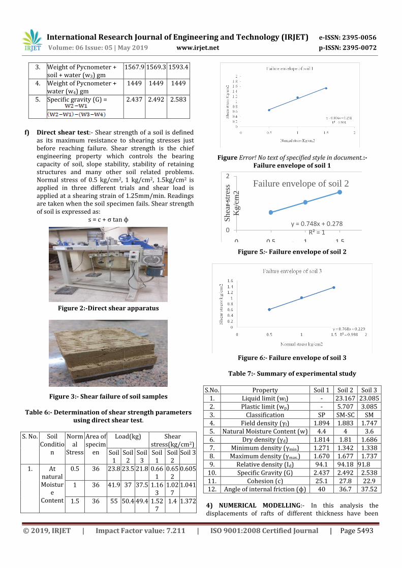
f) Direct shear test:- Shear strength of a soil is defined
as its maximum resistance to shearing stresses just before reaching failure. Shear strength is the chief engineering property which controls the bearing capacity of soil, slope stability, stability of retaining structures and many other soil related problems. Normal stress of 0.5 kg/cm2, 1 kg/cm2, 1.5kg/cm2 is applied in three different trials and shear load is applied at a shearing strain of 1.25mm/min. Readings are taken when the soil specimen fails. Shear strength of soil is expressed as:
s = c + σ tan ϕ
Figure 2:-Direct shear apparatus
Figure 3:- Shear failure of soil samples Table 6:- Determination of shear strength parameters
using direct shear test. S. No. Soil
Condition
Normal
Stress
Area of specim
en
Load(kg) Shear stress(kg/cm2)
Soil 1
Soil 2
Soil 3
Soil 1
Soil 2
Soil 3
1. At natural Moistur
e Content
0.5 36 23.8 23.5 21.8 0.661
0.652
0.605
1 36 41.9 37 37.5 1.163
1.027
1.041
1.5 36 55 50.4 49.4 1.527
1.4 1.372
Figure Error! No text of specified style in document.:- Failure envelope of soil 1
y = 0.748x + 0.278R² = 10
1
2
0 0.5 1 1.5 2
Sh
ear
stre
ss
Kg/c
m2
Normal stress Kg/cm2
Failure envelope of soil 2
Figure 5:- Failure envelope of soil 2
Figure 6:- Failure envelope of soil 3
Table 7:- Summary of experimental study
S.No. Property Soil 1 Soil 2 Soil 3 1. Liquid limit (wl) - 23.167 23.085 2. Plastic limit (wp) - 5.707 3.085 3. Classification SP SM-SC SM 4. Field density (γf) 1.894 1.883 1.747 5. Natural Moisture Content (w) 4.4 4 3.6 6. Dry density (γd) 1.814 1.81 1.686 7. Minimum density (γmin) 1.271 1.342 1.338 8. Maximum density (γmax.) 1.670 1.677 1.737 9. Relative density (Id) 94.1 94.18 91.8
10. Specific Gravity (G) 2.437 2.492 2.538 11. Cohesion (c) 25.1 27.8 22.9 12. Angle of internal friction (ϕ) 40 36.7 37.52
4) NUMERICAL MODELLING:- In this analysis the displacements of rafts of different thickness have been

International Research Journal of Engineering and Technology (IRJET) e-ISSN: 2395-0056
Volume: 06 Issue: 05 | May 2019 www.irjet.net p-ISSN: 2395-0072
© 2019, IRJET | Impact Factor value: 7.211 | ISO 9001:2008 Certified Journal | Page 5494
analysed under the same load by varying the pile length and pile thickness. In the first case, a 70cm thickness raft is analysed for displacements under a load of 250kN/m2. Displacements are obtained for the raft without piles and with 25 piles of 6.2 m length at varying diameter. In second case, the raft thickness has been reduced to 50cm and the displacements are obtained at varying pile length and diameter.
Displacements of raft at various conditions:-
a) Raft of thickness 70cm without any piles
Figure 7:- Displacements of raft without any piles
b) Displacements of piled-raft with piles of length 6.2m:-
Figure 8:- Displacements of piled-raft with piles of
length 6.2m and diameter 10cm
Figure9:- Displacements of piled-raft with piles of
length 6.2m and diameter 15cm
Figure10:- Displacements of piled-raft with piles of
length 6.2m and diameter 20cm.
Figure11:- Displacements of piled-raft with piles of length 6.2m and diameter 25cm.
Figure 12:- Displacements of piled-raft with piles of length 6.2m and diameter 30cm.

International Research Journal of Engineering and Technology (IRJET) e-ISSN: 2395-0056
Volume: 06 Issue: 05 | May 2019 www.irjet.net p-ISSN: 2395-0072
© 2019, IRJET | Impact Factor value: 7.211 | ISO 9001:2008 Certified Journal | Page 5495
Figure 13:- Settlements of 70cm thickness raft with 6.2m pile length at various diameters
c) Displacements of 70cm piled-raft with piles of
length 9m
Figure 14:- Displacements of piled-raft with piles of
length 9m and 30cm diameter.
Figure 15:- Comparison of 70cm raft with and without piles
Raft of thickness 50cm
d) Displacements of 50cmthickness raft without any piles
Figure 16:- Displacements of 50cm thickness raft
without any piles
Displacements of 50cm thickness raft with piles of 6.2m length
Figure 17:- Displacements of piled-raft with piles of length 6.2m and 10cm diameter
Figure 18:- Displacements of piled-raft with piles of
length 6.2m and 15cm diameter
International Research Journal of Engineering and Technology (IRJET) e-ISSN: 2395-0056
Volume: 06 Issue: 05 | May 2019 www.irjet.net p-ISSN: 2395-0072
© 2019, IRJET | Impact Factor value: 7.211 | ISO 9001:2008 Certified Journal | Page 5496
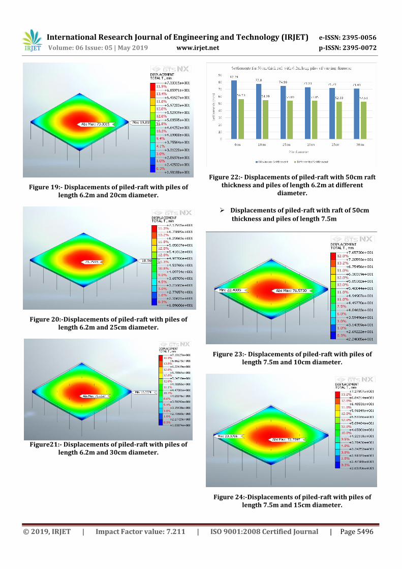
Figure 19:- Displacements of piled-raft with piles of length 6.2m and 20cm diameter.
Figure 20:-Displacements of piled-raft with piles of length 6.2m and 25cm diameter.
Figure21:- Displacements of piled-raft with piles of
length 6.2m and 30cm diameter.
Figure 22:- Displacements of piled-raft with 50cm raft thickness and piles of length 6.2m at different
diameter.
Displacements of piled-raft with raft of 50cm
thickness and piles of length 7.5m
Figure 23:- Displacements of piled-raft with piles of length 7.5m and 10cm diameter.
Figure 24:-Displacements of piled-raft with piles of length 7.5m and 15cm diameter.

International Research Journal of Engineering and Technology (IRJET) e-ISSN: 2395-0056
Volume: 06 Issue: 05 | May 2019 www.irjet.net p-ISSN: 2395-0072
© 2019, IRJET | Impact Factor value: 7.211 | ISO 9001:2008 Certified Journal | Page 5497
Figure 25:- Displacements of piled-raft with piles of
length 7.5m and 20cm diameter.
Figure 26:- Displacements of piled-raft with piles of length 7.5m and 25cm diameter.
Figure 27:- Displacements of piled-raft with piles of length 7.5m and 30cm diameter
Figure 28:- Displacements of piled-raft with 50cm raft thickness and piles of length 7.5m at different
diameter.
Displacements of piled-raft with raft of 50cm thickness and piles of length 9m
Figure 29:- Displacements of piled-raft with piles of
length 9m and 10cm diameter.
Figure 30:- Displacements of piled-raft with piles of length 9m and 15cm diameter.

International Research Journal of Engineering and Technology (IRJET) e-ISSN: 2395-0056
Volume: 06 Issue: 05 | May 2019 www.irjet.net p-ISSN: 2395-0072
© 2019, IRJET | Impact Factor value: 7.211 | ISO 9001:2008 Certified Journal | Page 5498
Figure 31:- Displacements of piled-raft with piles of
length 9m and 20cm diameter.
Figure 32:- Displacements of piled-raft with piles of length 9m and 30cm diameter.
Figure 33:- Displacements of piled-raft with piles of length 9m and 30cm diameter.
Figure 34:- Displacements of piled-raft with 50cm raft thickness and piles of length 9m at different diameter.
Raft of thickness 90cm
Figure 35:- Displacements of 90cm thickness raft
without any piles.
Figure 36:- Displacements of rafts of various thicknesses.
7. CONCLUSIONS
1. The introduction of piles irrespective of the raft thickness results in considerable decrease in the foundation settlements.

International Research Journal of Engineering and Technology (IRJET) e-ISSN: 2395-0056
Volume: 06 Issue: 05 | May 2019 www.irjet.net p-ISSN: 2395-0072
© 2019, IRJET | Impact Factor value: 7.211 | ISO 9001:2008 Certified Journal | Page 5499
2. Use of piled raft can be used to reduce the settlements of the raft as well as the material resources by reduction in the raft thickness. 3. Midas GTS NX proves to be efficient software in the analysis of piled raft foundation with auser friendly interface and can aid in the analysis of complex problems. 8. FUTURE SCOPE OF WORK
1. The behaviour of the piled raft foundation can be analysed for the increments in the pressure load on the raft.
2. The foundation system can be analysed with a change in the number of piles and their different arrangements.
3. In the present study the settlements corresponding to a uniformly distributed pressure load were studied. The analysis can also be performed for the case where the load is acting at the location of structural columns.
REFERENCES 1. Poulos, H. G. “Piled raft foundations: design and
applications’’ Geotechnique 51, No. 2, 95-113 (2001). 2. W. Allen. Mark “Effective use of Finite Element
Analysis in Geotech Engineering” 3. Goel Tarun, Sonthwal Vinod “A review on slope
stability analysis by strength reduction method using MIDAS GTS” International Journal of Innovative Research in Science, Engineering and Technology Vol. 6, Issue 8, August 2017 (2017)
4. Poulos, H. G. “Methods of analysis of piled raft foundations’’ International Society of Soil Mechanics and Geotechnical Engineering (2001)
5. Poulos H. G. “The piled raft foundation for the Burj Dubai – design and performance’’ IGS-Ferroco Terzaghi Oration (2008)
6. E.Y.Oh, Huang M, Surarak C “Finite element modelling for piled raft foundation in sand” EASEC-11, Taipei, Taiwan (2008)
7. Poulos H.G., J.C. Small and H. Chow “Piled Raft Foundations for Tall Buildings” Geotechnical Engineering Journal of the SEAGS & AGSSEA (2011)
8. Koch Edina, Szep Janos, Ray Richard “Modeling of Combined Pile Raft Foundation by Midas-GTS and Axis 3-D Software” (2011)
9. Sharma V.J, Vansanvala S.A, Solanki C.H “Composite piled raft foundation with intermediate cushion in layered soil under seismic forces“ComputationalMethods in Civil Eng., Vol. 3, 2 (2012) 15-28 (2012)
10. Srilakshmi G, Moudgalya N S Darshan “Analysis of piled raft foundation using finite element method” International Journal of Engineering research and science & technology ISSN 2319-5991 Vol. 2, No. 3 (2013)
11. Nguyen Chung Dinh Dang, Jo Seong-Bae, Kim Dong-Soo “Design method of piled-raft foundations under vertical load considering interaction effects” Computers and Geotechnics Volume 47, January 2013, Pages 16–27 (2013)
12. Radhika. R, .Jeyapriya S.P, Soundrapandiyan P “Parametric Study and Numerical Analysis of Piled Raft Foundation on Soft Clay” International journal for research in emerging science and technology, volume-2, issue-4, April-2015 (2015)
13. Batali Loretta “Numerical modelling of piled raft foundations. Modelling particularities and comparison with field measurements” International Conference on Soil Mechanics and Geotechnical Engineering, Seoul 2017(2017)