Analysis of Parallelism and Deadlocks in Distributed...
37
Analysis of Parallelism and Deadlocks in Distributed-Time Logic Simulation Larry Soule and Anoop Gupta Technical Report No. CSL-TR-89-378 May 1989 This research has been supported by DARPA contract NOOO14-87-K0828. Authors also acbowledge support from Digital Equipment Corp. and a Graduate Fellowship from the National Science Foundation.
Transcript of Analysis of Parallelism and Deadlocks in Distributed...

Analysis of Parallelism and Deadlocks inDistributed-Time Logic Simulation
Larry Soule and Anoop Gupta
Technical Report No. CSL-TR-89-378
May 1989
This research has been supported by DARPA contract NOOO14-87-K0828. Authorsalso acbowledge support from Digital Equipment Corp. and a GraduateFellowship from the National Science Foundation.
Analysis of Parallelism and Deadlocks inDistributed-Time Logic Simulation
Larry Soule and Anoop Gupta
Technical Report No. CSL-Tr-89-378
May 1989
Computer Systems LaboratoryDepartments of Electrical Engineering and Computer Science
Stanford UniversityStanford, CA 943054055
Abstract
This paper explores the suitability of the Chandy-Misra algorithm for digital logic simulation.We use four realistic circuits as benchmarks for our analysis, including the vector-unit controllerfor the Titan supercomputer from Ardent. Our results show that the average number of logicelements available for concurrent execution ranges from 10 to 111 for the four circuits, with anoverall average of 68. Although this is twice as much parallelism as that obtained by traditionalevent-driven algorithms for these circuits, we feel it is still too low. One major factor limitingconcurrency is the large number of global synchronization points --- “deadlocks” in theChandy-Mrsra terminology -- that occur during execution. Towards thenumber of deadlocks, the paper %
oal of reducing theeadlocks that occur
during digital logic simulation. 8resents a classification of the types ofour different
terms of circuit structure. Usin YEis are identified and described intuitively in
these deadlock occurrences an%domain specific owledge, we propose methods for reducinggive some preliminary results regarding the effectiveness of
these methods. For one of the benchmark circuits, the use of the{\em all} deadlocks and increased the average arallelism from i
roposed techniques eliminated0 to 160. We believe that the
use of such domain knowledge will make trle Chandy-Misra algorithm significantly moreeffective than it would be in its generic form, We also present some preliminary resultscomparing the performance of the Chandy-Misra algorithm versus a parallel event-drivenalgorithm.
Key Words and Phrases: Distributed Logic Simulation, Chandy- Msra algorithm, Deadlock.

-l-
Contents
1 Introduction 3
2 Background 4
3 Experimental Environment 6
3.1 Benchmark Circuits . . . . . . . . . . . . . . . . . . . . . . . . . . . . . . . . . . . . 6
3 . 2 SimulationModel . . . . . . . . . . . . . . . . . . . . . . . . . . . . . . . . . . . . . 7
3 . 3 HardwareDetails . . . . . . . . . . . . . . . . . . . . . . . . . . . . . . . . . . . . . 7
3.3.1 Multiprocessor Simulation With Tango . . . . . . . . . . . . . . . . . . . . . . 8
4 Parallelism Measurements 8
5 Characterizing Deadlocks 11
5.1 Registers and Generator Nodes . . . . . . . . . . . . . . . . . . . . . . . . . . . . . . 11
5.1.1 Proposed Solutions . . . . . . . . . . . . . . . . . . . . . . . . . . . . . . . . 12
5.2 Multiple Paths with Different Delays . . . . . . . . . . . . . . . . . . . . . . . . . . . 13
5.2.1 Proposed Solutions . . . . . . . . . . . . . . . . . . . . . . . . . . . . . . . . 14. 5.3 Order of Node Updates . . . . . . . . . . . . . . . . . . . . . . . . . . . . . . . . . . 14
5 . 3 . 1 ProposedSolutions . . . . . . . . . . . . . . . . . . . . . . . . . . . . . . . . 16
5 . 4 UnevaluatedPath . . . . . . . . . . . . . . . . . . . . . . . . . . . . . . . . . . . . . 16
5.4.1 Proposed Solutions . . . . . . . . . . . . . . . . . . . . . . . . . . . . . . . . 18
5.5 Summary of the Contributions From Each Deadlock Type . . . . . . . . . . . . . . . . 18
6 Preliminary Results 19
6 . 1 Speed-upCurves . . . . . . . . . . . . . . . . . . . . . . . . . . . . . . . . . . . . . . 19
6.2 Overheads in the Chandy-Misra and Event-Driven Algorithms . . . . . . . . . . . . . . 21
6.3 Maximum Parallelism Available From This Approach . . . . . . . . . . . . . . . . . . 21
6.4 Exploiting Element Behavior . . . . . . . . . . . . . . . . . . . . . . . . . . . . . . . 22
6 . 5 OneLevelChecking . . . . . . . . . . . . . . . . . . . . . . . . . . . . . . . . . . . . 25
6.6 Global Event Counting . . . . . . . . . . . . . . . . . . . . . . . . . . . . . . . . . . 28
6.7 Deadlock Avoidance by Always Sending NULLS . . . . . . . . . . . . . . . . . . . . . 29
7 Conclusions 29
- 2 -
8 Acknowledgments
A Implementing Inertial Delays
B Generalized Sensitization
30
32
32
Analysis of Parallelism and Deadlocks in Distributed-TimeLogic Simulation
Larry Soule and Anoop GuptaComputer Systems LaboratoryStanford University, CA 94305
Abstract
. .
This paper explores the suitability of the Chandy-Misra algorithm for digital logic simulation.We use four realistic circuits as benchmarks for our analysis, including the vector-unit controller for theTitan super-computer from Ardent- Our results show that the average number of logic elements availablefor concurrent execution ranges from 10 to 111 for the four circuits, with an overall average of 68.Although this is twice as much parallelism as that obtained by traditional event-driven algorithms forthese circuits, we feel it is still too low. One major factor limiting concurrency is the large numberof global synchronization points - “deadlocks” in the Chandy-Misra terminology - that occur duringexecution. Towards the goal of reducing the number of deadlocks, the paper presents a classification ofthe types of deadlocks that occur during digital logic simulation. Four different types are identified anddescribed intuitively in terms of circuit structure. Using domain specific knowledge, we propose methodsfor reducing these deadlock occurrences and give some preliminary results regarding the effectivenessof these methods. For one of the benchmark circuits, the use of the proposed techniques eliminated aNdeadlocks and increased the average parallelism from 40 to 160. We believe that the use of such domainbaowledge will make the Chandy-Misra algorithm significantly more effective than it would be in itsgeneric form. We also present some preliminary results comparing the performance of the Chandy-Misraalgorithm versus a parallel event-driven algorithm I.
1 Introduction
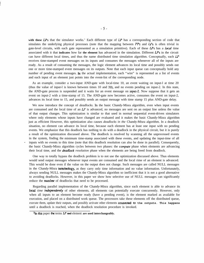
Logic simulation is a very common and effective technique for verifying the behavior of digital designs beforethey are physically built. A thorough verification can reduce the number of expensive prototypes that areconstructed and save vast amounts of debugging time. However, logic simulation is extremely time consumingfor large designs where verification is needed the most The result is that for large digital systems only partialsimulation is done, and even then the CPU time mquired may be days or weeks. The use of parallel computersto run these logic simulations offers one promising solution to the problem.
The two traditional parallel simulation algorithms for digital logic have been (i) compiled-mode simulationsand (ii) centralized time event-driven simulations. In compiled-mode simulations, each logic element in thecircuit is evaluated on each clock tick The main advantage is simplicity, with the main disadvantage being thatthe processors do a lot of avoidable work, since typically only a small fraction of logic elements change stateon any clock tick. The algorithm’s simplicity makes it suitable for direct implementation in hardware [2,6], but
‘A condensed version of the first part of this paper appears in the Proceedings of the 26th Degisn AutomationConferen@ 121.
-4-
such implementations make it difficult to incorporate user-defined models or represent the circuit elements atdifferent levels of abstraction. In the second approach of centralized time event-driven algorithms, only thoselogic elements whose inputs have changed are evaluated on a clock tick. This avoids the redundant work done inthe previous algorithm, however the notion of the global clock and synchronized advance of time for all elementsin the circuit limits the amount of concurrency [1,10,14]. These centralized time approachs work efficiently onmultiprocessors with 10 nodes or so [9,11], but for larger machines we need alternative approaches that moveaway from this centralized advance of the simulation clock.
The approach generating the most interest recently is the Btyant/Chandy-Mista distributed time discrete-eventsimulation algorithm [3,4]. It allows each logic element to have a local clock, and the elements communicatewith each other using time-stamped messages. In this paper, we explore the suitability of the Chandy-Misraalgorithm for parallel digital logic simulation. We use four realistic circuits as benchmarks for our analysis. Infack one of the circuits is the vector-unit controller for the Titan supercomputer from Ardent[7]. Our resultsshow that the basic unoptimized Chandy-Misra algorithm results in an average concurrency (by concurrency werefer to the number of logic elements that could be evaluated in parallel if there were infinite processors) of68 for the four circuits. For two of the benchmark circuits which were also studied in an earlier paper [lo),the unoprimized Chandy-Misra algorithm extracted 40% and 107% more parallelism than the centralized timeevent-driven simulation algorithm.
The 68-fold average concurrency observed in the four benchmark circuits, however, is still too low. Once allthe overheads (e.g. distributed deadlock detection, bus traffic, cache coherency, etc.) are taken into account, the68-fold concurrency may not result in much more than 20 fold speed-up. One major factor limiting concurrencyis the large number of global synchronization points - “deadlocks” in the Chandy-Misra terminology - thatoccur during execution We believe that understanding the nature of the deadlocks, why they occur and howtheir number can be reduced, is the key to getting increased concurrency from the Chandy-Misra algorithm. Tothis end, the paper presents a classification of the types of deadlocks that occur during digital logic simulation.Four different types are idatied and described. Using domain specific knowledge, we then propose methodsfor reducing these deadlock occurrences. For one benchmark circuit, we show how using information aboutlogic gates can eliminate all of the deadlocks. We believe that the use of such domain knowledge will makethe Chandy-Misra algorithm significantly more effective than it would be in its generic form. To get an ideaof how this average concurrency translates into real parallel performance, speed-up curves are presented for thealgorithms running on a simulated 60-processor machine.
The organization of the rest of the paper is as follows. The next section describes the basic Chandy-Misraalgorithm. Then we describe the four benchmark circuits that were simulated to get the measurements. Section 4presents mczurements of the parallelism extracted by the algorithm and Section 5 presents the classification ofthe deadlocks and ways for resolving them. Section 6 presents some speed-up curves comparing the Chandy-Misra algorithm and an event-driven algorithm along with some preliminary results on the proposed solutionsfor avoiding deadlock by exploiting knowledge of element behavior. Finally, Section 7 presents a summary ofthe results and discusses directions for future research
2 Background
We begin with a brief description of the basic Chandy-Misra algorithm [4] as applied to the domain of digitallogic simulation. The simulated circuit consists of several circuit elements (transistors, gates, latches, etc) calledphysical processes (PP). One or more of these PPs can be combined into a logical process (Lp), and it is
I
-5-
with these Lps that the simulator works.’ Each different type of L.P has a corresponding section of code thatsimulates the underlying physical processes (note that the mapping between PPs and Lps is often trivial ingate-level circuits, with each gate represented as a simulation primitive). Each of these Lps has a Zocaf timeassociated with it that indicates how far the element has advanced in the simulation. Different Lps in the circuitcan have different local times, and thus the name distributed time simulation algorithm. Conceptually, each Lpreceives time-stamped event messages on its inputs and consumes the messages whenever all of the inputs areready. As a result of consuming the messages, the logic element advances its local time and possibly sends outone or more time-stamped event messages on its outputs. Note that each input queue can conceptually hold anynumber of pending event messages. Ln the actual implementation, each “wire” is represented as a list of eventsand each input of an element just points into the event-list of the corresponding node.
As an example, consider a two-input AND-gate with local-time 10, an event waiting on input-l at time 20(thus the value of input-l is known between times 10 and 20). and no events pending on input-2. In this state,the AND-gate process is suspended and it waits for an event message on input-2. Now suppose that it gets anevent on input-2 with a time-stamp of 15. The AND-gate now becomes active, consumes the event on input-2,advances its local time to 15, and possibly sends an output message with time stamp 15 plus AND-gate delay.
We now introduce the concept of deadlocks. In the basic Chandy-Misra algorithm, even when input eventsare consumed and the local time of an LP is advanced, no messages are sent on an output line unless the valueof that output changes. This optimization is similar to that used in normal sequential event-driven simulatorswhere only elements whose inputs have changed are evaluated and it makes the basic Chandy-Misra algorithmjust as efficient However, this optimization also causes deadlocks in the Chandy-Misra algorithm. In a deadlocksituation, no element can advance its local time, because each element has at least one input with no pendingevents. We emphasize that this deadlock has nothing to do with a deadlock in the physical circuit, but it is purelya result of the optimization discussed above. The deadlock is resolved by scanning all the unprocessed eventsin the system, finding the minimum time-stamp associated with these events, and updating the input-time of all
- inputs with no events to this time (note that this deadlock resolution can also be done in parallel). Consequently,the basic Chandy-Misra algorithm cycles between two phases: the cornpure phase when elements are advancingtheir local time, and the deadlock resolution phase when the elements are being freed from deadlock.
One way to totally bypass the deadlock problem is to not use the optimization discussed above. Thus elementswould send output messages whenever input events are consumed and the local rime of an element is advanced.This would be done even if the value on the output does not change. Such messages are called NULL messagesin the Chandy-Misra terminology, as they carry only time information and no value information. Unfortunately,always sending NULL messages makes the Chandy-Misra algorithm so inefficient that it is not a good alternativeto avoiding deadlocks. However, in this paper we show how selective use of NULL messages can significantlyreduce the numbs of deadlocks that need to be processed.
Regarding parallel implementation of the Chandy-Misra algorithm, since each element is able to advance itslod time independentZy of other elements, all elements can potentially execute concurrently. However, onlywhen all inputs to an element become ready (have a pending event), is the element marked as available forexecution, and placed on a distributed work queue. The processors take these elements off the distributed queue,execute them, update their outputs, and possibly activate other elements co~ected to the outputs. This happensuntil a deadlock is reached, when the deadlock resolution procedure is invoked.
%I tfris paper the terms LP and element are used interchangeably.
- 6 -
3 Experimental Environment
This section describes the circuits used to evaluate the algorithms, the details of the simulator (e.g. the delaymodel used), and the hardware the experiments were run on.
3.1 Benchmark Circuits
In this section, we first provide a brief description of the benchmark circuits used in our study and then somegeneral statistics characterizing these circuits. The four circuits that we use are:
1. Ardent-l: This circuit is that of the vector control unit (VCU) for the Ardent Titan graphics supercomputer(7).The VCU is implemented in a 15/l CMOS gate array technology and it provides the interface among theinteger processing unit, the register file, and the memory. It also allows multiple scalar instructions to beexecuted concurrently by scoreboarding. It consists of approximately 45,000 two-input gates.
2. H-FRISC: A small RISC generated by the HERCULES [8] high-level synthesis system from the 1988 HighLevel Synthesis Workshop. The RISC instruction set is stack based and fairly simple. This circuit consistsof approximately 11,000 two-input gates.
3. Multiplier: This circuit represents the inner core of a custom 3/r CMOS combinational 16x16 bit integermultiplier. Multiplies are pipelined and have a latency time of 7Ons. The approximate complexity is 7,000two-input gates.
4. 8080: This circuit corresponds to a TT’L board design that implements the 8080 instruction set. The design ispipelined, runs 8080 code at a speed of 3-5 MIPS, and provides an interface that is “pin-for-pin” compatiblewith the 8080. The approximate complexity is 3,000 two-input gates.
We note that the benchmark circuits cover a wide range of design styles and complexity - we have a largemixed-level synchronous gate array; a medium gate-level synthesized circuit; a medium gate-level combinationalchip; and a smalI synchronous board-level design The fact that we have both synchronous pipelined circuitsand totally combinational circuits is also important, because they exhibit very different deadlock behavior duringsimulation.
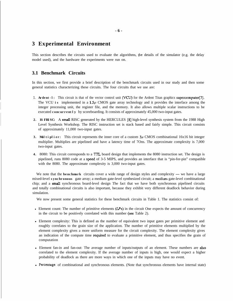
We now present some general statistics for these benchmark circuits in Table 1. The statistics consist of:
l Element count: The number of primitive elements (U’s) in the circuit One expects the amount of concurrencyin the circuit to be positively correlated with this number (see Table 2).
l Element complexity: This is defined as the number of equivalent two input gates per primitive element androughly correlates to the grain size of the application. The number of primitive elements multiplied by theelement complexity gives a more uniform measure for the circuit complexity. The element complexity givesan indication of the compute time reqired to evaluate a primitive element, and thus specifies the grain ofcomputation
l Element fan-in and fan-out: The average number of inputs/outputs of an element. These numbers are alsocorrelated to the element complexity. If the average number of inputs is high, one would expect a higherprobability of deadlock as there are more ways in which one of the inputs may have no event.
l Per c enta ge of combinational and synchronous elements. (Note that synchronous elements have internal state)
--J-
Table 1: Basic Circuit Statistics
statistic Ardent-lElement Count 13349Element Complexity 3.4Element Fan-m 2.72
11 Element Fanout II 1.296 Svnchronous Elements II 11.2% Comb. Elements II 88.8
c
H-FRLSC Mult-16 80808,076 4,990 281
1.4 1.4 12.02.14 2.14 5.781.0 1.0 2.632.8 0.0 16.7
l Net count: The number of wires in the circuit,
a Net fan-out: The average number of elements a wire is attached to. The Ardent and 8080 circuits have someglobal buses that affect many components thus their net fan-out numbers are high.
l Representation: The level of representation of the simulation primitives. A circuit made up of only logicgates and one-bit registers is at the gate-level while a design made up of ‘IX-chip components is at theRTL-IeveL
. . l Unit of delay: Each output pm of each element is assigned a delay value at netlistxompile time. The delayis specified in terms of the basic unit of delay.
3.2 Simulation Model
A fixed delay model is used and all delays are greater than zero. This means that each output pm of each elementis assigned a non-zero delay value at netlistcompile time. The propagation delays are all specified in terms ofthe basic unit of delay (see Table 1). Traditional event-driven simulators usually implement a more complexdelay model including inertial delays and spike analysis. These are implemented by canceling events alreadyscheduled in the future. These accuracy enhancements are more complicated to implement in a conservativedistributed-time simulation scheme since canceling an event violates the basic premise of “send an event onlywhen you’re swc it’s ok”. However, inertial delays and spike analysis can be implemented by adding some codeto the elements and nodes in question (see Appendix A for implementation details). This could cost as muchas 50% in terms of performance since the node evaluations take longer and may introduce deadlocks. If spikeanalysis or usage of inertial delays can be limited to only a portion of the circuit, the performance impact wouldbeminimaL
3.3 Hardware Details
Implementations in two environments were used in collecting the results. One implementation runs on theEncore Multimax, a shared-memory multiprocessor with sixteen NS32032 processors, each processor delivering
-8-
approximately 0.75 MIPS. The other implementation runs under a simulated multiprocessor environment calledTango [5].
33.1 Multiprocessor Simulation With Tango
Tango is a software tracing system that helps in evaluating parallel applications and multiprocessors. Tangosimulates multiprocessors by creating a real process for each process in the application code. These processesare then multiplexed onto a single processor. With this method, the system can simulate the timing behavior ofthe parallel application at three levels: at each global synchronization points, at each shared memory reference,or at each memory reference. This is done by associating a local clock with each user process being traced.The clocks are updated either at the end of each basic block, at each synchronization point, or at each memoryreference depending on the desired level of timing detail. Tango schedules the processes in such a way thatensures correctness between the process clocks at the level of the timing detail (the trade-off being wallclocktime vexsus timing accuracy). The methods used in Tango are not affected by the programming model or thearchitecture model.
4 Parallelism Measurements
In this section, we discuss how parallelism is exploited by the Chandy-Misra algorithm and present data regardingthe amount of concurrency available in the four benchmark circuits. We also present data regarding the granularityof computation, the number of deadlocks per clock cycle, and the amount of time spent in deadlock resolution.
Since we are interested in the parallel implementations of the Chandy-Misra algorithm, the first question thatr arises is how much speed-up can be obtained if there were arbitrarily many processors, and if there were no
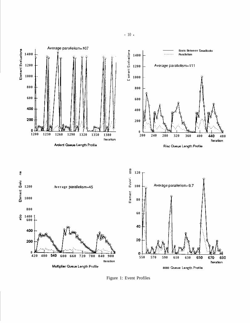
synchronization or scheduling overheads. We call this measure the concwrency or intrinsic parallelism of thecircuits under Chandy-Misra algorithm. For our concurrency data, we further assume that all element evaluationstake awtly one unit of time. Thus, the simulation proceeds as follows. After a deadlock and the ensuingdeadlock resolution phase, all elements that are activated (i.e., have at least one event on each of their inputs) areprocesstd. This happens in exactly one unitcost cycle as we assume arbitrarily many processors. The numberof elements that arc evaluated constitutes the concurrency for this izerafion. The evaluation of the elements, ofcourse, results in the activation of a whole new set of elements, and these are evaluated in one cycle in the nextiteration, The computation proceeds through these iterations until a deadlock is reached, and we start all overagain ‘Epically, four or five iterations are completed before a deadlock is reached.
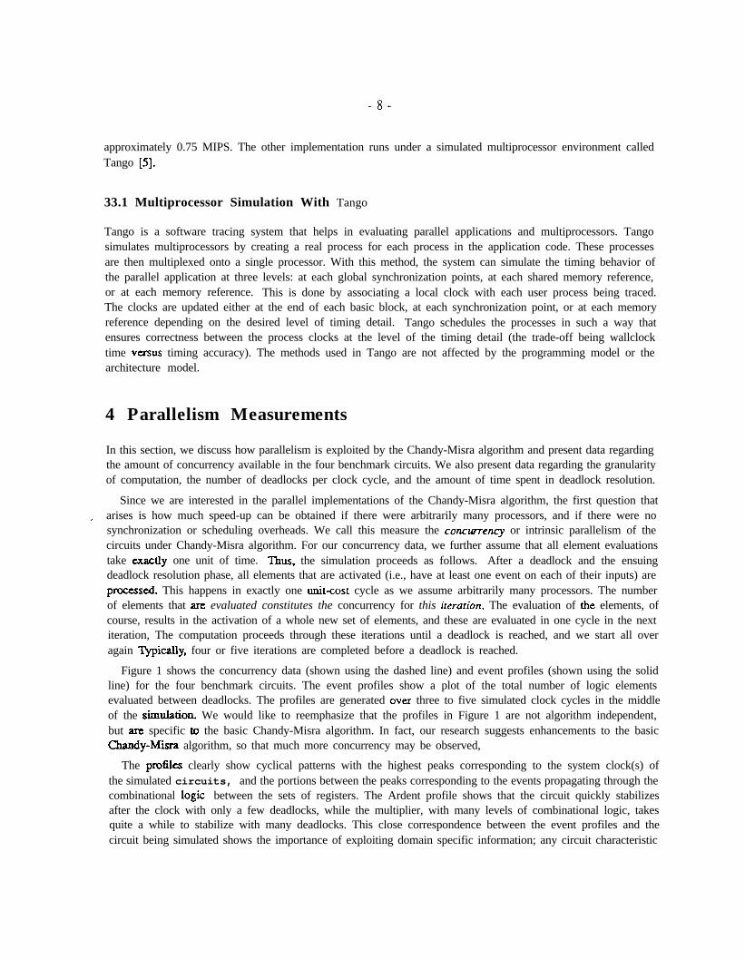
Figure 1 shows the concurrency data (shown using the dashed line) and event profiles (shown using the solidline) for the four benchmark circuits. The event profiles show a plot of the total number of logic elementsevaluated between deadlocks. The profiles are generated over three to five simulated clock cycles in the middleof the simu.latior~ We would like to reemphasize that the profiles in Figure 1 are not algorithm independent,but arc specific to the basic Chandy-Misra algorithm. In fact, our research suggests enhancements to the basicChandy-Miss algorithm, so that much more concurrency may be observed,
The profiles clearly show cyclical patterns with the highest peaks corresponding to the system clock(s) ofthe simulated circuits, and the portions between the peaks corresponding to the events propagating through thecombinational logic between the sets of registers. The Ardent profile shows that the circuit quickly stabilizesafter the clock with only a few deadlocks, while the multiplier, with many levels of combinational logic, takesquite a while to stabilize with many deadlocks. This close correspondence between the event profiles and thecircuit being simulated shows the importance of exploiting domain specific information; any circuit characteristic
-9-
Table 2: Simulation Statistics
statistic 11 Ardent-l 1 H-FRISC 1 Mult-16 1 8080
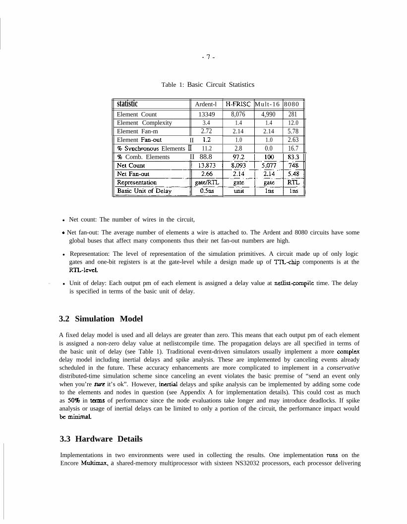
we change or exploit will be directly reflected in the event profiles. Understanding how these changes affectthe profiles and beiig able to predict them is important in obtaining better performance. A summary of theconcurrency information is also presented in Table 2. The top line of the table shows the concurrency asaveraged over all iterations in the simulation.
In addition to knowing how many concurrent element evaluations or tasks are available, we also need to knowthe task granularity and how often deadlocks (global processor synchronizations) occur. The granularity or basictask size for our application (a model evaluation) includes checking the input channel times, executing the modelcode, calculating the least next event and possibly activating the elements in its fan-out, The numbers discussingtask granularity and frequency of deadlocks are summari zed in Table 2. The table also presents the following
- ratios that help characterize the performance of the Chandy-Misra algorithm:
l Deadlock ratio (DR): Number of element evaluations divided by the number of deadlocks.
l Cycle ratio (CR): Number of element evaluations divided by the number of simulated clock cycles.
l Deadlocks per cycle: Number of deadlocks divided by the number of simulated clock cycles.
Since increased parallelism was the main motivation for using the Chandy-Misra algorithm, we now comparethe concurrency it obtains to that obtained using a traditional event-based algorithm. For our comparison, weusetheconcurrency data presented for the 8080 and multiplier circuits in a parallel event-driven environment in[ll,lO]. These papers showed that the available concurrency was about 3 for the 8080 and 30 for the multiplier.From Table 2, the corresponding numbers for the Chandy-Misra algorithm are 10 for the 8080 and 45 for themultiplier. The fact that the concurrency increases only by a factor of 15 for the multiplier and 3.3 for the8080 (only bringing it up to 10) is somewhat disappointing, since Chandy-Misra algorithm is more complexto implement, Howeva, we show that using the techniques proposed in the next section, the Chandy-Misraalgorithm can be suitably enhanced to show much higher concurrency.
The last two lines of Table 2 give data about the average time taken by each call to deadlock resolution and thetotal fraction of time spent in deadlock resolution. The cost of resolving a deadlock for the three larger circuitsis indeed high, especially when compared to the cost of evaluating a logic element (see the granularity line).In the time it takes to resolve one deadlock in the Ardent simulation, 700 logic element activations could havebeen processed. For the H-FRISC, 350 elements could have been evaluated, and in the multiplier, 275 elementscould have been evaluated. However, for the 8080 with 281 elements, the deadlock resolution overhead is not
E-g 1400 c
Aver
3?w 1200Ei!Qcil 1000
800
600
:
.
‘age parallelism=1 07
400
200
01200 1230 1260 1290 1320 1350 1380 200 240 280 320 360 400 440 480tteration Iteration
Ardent Queue Length Profile Rise Queue Length Profile
E
-2 1400
22Lu 1200
t
Average parallelism=45
FE@iz 1000
800
600t
0420 480 540 600 660 720 780 840 900
Iteration
Multiplier Queue Length Profile
- 10 -
?.z 14003-ii12 1200TitiQ)iii 1000
800
600
Evats Between Deadkxks. . . . . . . Parallelism
Average parallelism=1 11
if 120.-3sLs 100
E5111 80
60
550 570 590 610 630 6iO 690Iteration
8080 Queue Length Profile
Figure 1: Event Profiles

- 11 -
too high taking the time of only 4 element evaluations. This is because there are so few elements (only l/40 asmany elements as the Ardent-l) to be checked and because each evaluation of an RTL element is about 34 timeslonger than the evaluation of a typical logic gate. Unfortunately the trend that emerges is: the more elements inthe circuit, the larger the fraction of execution time consumed by deadlock resolution. This remains a problem,but in our research, we are also exploring techniques to reduce the deadlock resolution time significantly bycaching information from previous simulation runs of the same circuit. No results are available at this time.
5 Characterizing Deadlocks
Even though there is reasonable parallelism available in the execution phase of the Chandy-Misra algorithm,deadlock resolution is so expensive in the larger circuits that it consumes 40-60% of the total execution time.Clearly we have to reduce this percentage in order to get good overall parallel performance. The first step towardsthis reduction is understanding why deadlocks occur and how they can be avoided. The types of deadlock thatoccur in logic simulation are characterized in this section and this characterization gives us insight into whataspects of logic simulation can be effectively exploited to achieve good overall performance.
In the logic simulations that were studied, the elements that became deadlocked can be put into two categories:(i) those deadlocked due to some aspect of the circuit structure (e.g topology, nature of registers, feed-back) and(ii) those deadlocked due to low activity levels (e.g. typically only 0.1% of elements need to be evaluated oneach time step in eventdriven simulators[lO]). In the following subsections, descriptions and examples of eachof the types of deadlock are given, along with measurements that show how much each type contributes to thewhole.
5.1 Registers and Generator Nodes
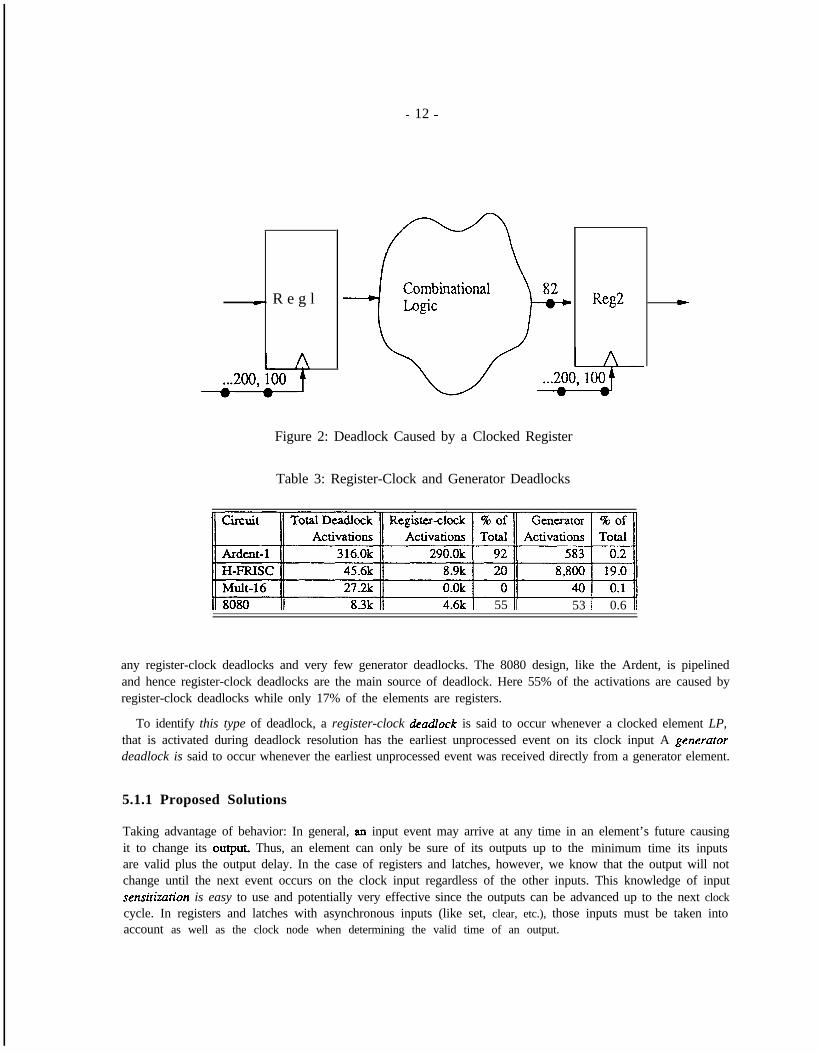
In a typical circuit, enough time is allowed for the changes in the output of one set of registers to propagate all theway to the next set of registers in the datapath and stabilize before the registers are clocked again For example,in Figure 2, the critical path of the combinational part of the circuit is 82~s. and the clock node changes every1OOns to allow everything to stabilize. Regl is clocked at the start of the simulation, and the events propagatethrough the combinational logic, generating an event at time 82. This event at time 82 is consumed by Reg2since the clock node is defined for all time in this cxample. However, the next event for Reg2 at time 100 is notconsumed since the input to the latch is only defined up to time 82, not 100. This causes Reg2 to block and thedeadlock resolution phase is entered
Generator deadlocks are similar to register deadlocks. Generators supply the external stimulus (e.g. systemclocks, reset, inputs, etc.), and usually have no inputs. Since they do not have any inputs, they can be evaluatedfor all time at the beginning of the simulation. The events output by these generators cause deadlocks just likethe register clocks in the previous example. Generators and register clocks combine to be a very large source ofdeadlocks since most circuits have many registers, latches and generator nodes.
In Table 6 we see that for the Ardent, registerclock deadlocks account for 92% of all the elements activatedin the deadlock resolution phase even though registers only make up 11% of the elements. This is mainly dueto the pipelined nature of the Ardent design where there is only a small amount of combinational logic betweenregister stages. In the case of the RISC design, there is more combinational logic between the registers thanthe Ardent and more logic gates connected to the input stimulus generators. Thus registerclock and generatordeadlocks both cause around 20% of the deadlock activations for a total of 40%. In the multiplier design, thereare many levels of logic between the inputs and outputs and does not have any registers. Thus there can not be
- 12 -
# R e g l Reg2
Figure 2: Deadlock Caused by a Clocked Register
Table 3: Register-Clock and Generator Deadlocks
8.3k 11 4.6k I 55 11 53 1 0.6 11
t
any register-clock deadlocks and very few generator deadlocks. The 8080 design, like the Ardent, is pipelinedand hence register-clock deadlocks are the main source of deadlock. Here 55% of the activations are caused byregister-clock deadlocks while only 17% of the elements are registers.
To identify this type of deadlock, a register-clock deadlock is said to occur whenever a clocked element LP,that is activated during deadlock resolution has the earliest unprocessed event on its clock input A generarordeadlock is said to occur whenever the earliest unprocessed event was received directly from a generator element.
5.1.1 Proposed Solutions
Taking advantage of behavior: In general, an input event may arrive at any time in an element’s future causingit to change its output. Thus, an element can only be sure of its outputs up to the minimum time its inputsare valid plus the output delay. In the case of registers and latches, however, we know that the output will notchange until the next event occurs on the clock input regardless of the other inputs. This knowledge of inputsensirization is easy to use and potentially very effective since the outputs can be advanced up to the next clockcycle. In registers and latches with asynchronous inputs (like set, clear, etc.), those inputs must be taken intoaccount as well as the clock node when determining the valid time of an output.
- 13 -
Figure 3: Deadlock Due to Paths of Different Delays
Fan-out Globbing: This technique reduces the overhead and the time needed to perform deadlock resolutionRecall that a particular Lp is composed of many PPs. These PPs can be combined in different ways to formlarger units. Combining many registers that share the same clock node will reduce the overhead of activatingeach register separately. Typically hundreds of one-bit registers and gates are co~ectai to the clock node(s) andoften times during deadlock resolution, the minimum event is on the clock node (as in the example above). Ifwe combine these registers and gates in groups of n, we call this grouping fan-our globbing with a clumping
. facror of n since we are combining the fan-out elements of the clock This reduces the overhead of insertingand deleting the elements in the evaluation queue. However, since it combines elements, it also reduces theparallelism available. We are currently looking into just how much reduction in overhead and parallelism thiscauses.
5.2 Multiple Paths with Different Delays
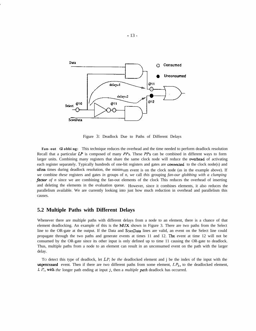
Whenever there are multiple paths with different delays from a node to an element, there is a chance of thatelement deadlocking. An example of this is the MUX shown in Figure 3. There are two paths from the Selectline to the OR-gate at the output. If the Data and ScanData lines are valid, an event on the Select line couldpropagate through the two paths and generate events at times 11 and 12. The event at time 12 will not beconsumed by the OR-gate since its other input is only defined up to time 11 causing the OR-gate to deadlock.Thus, multiple paths from a node to an element can result in an unconsumed event on the path with the largerdelay.
TO detect this type of deadlock, let LPi be the deadlocked element and j be the index of the input with theUXI~~OCCSS~~ event. Then if there are two different paths from some element, LPk, to the deadlocked element,L P,, with the longer path ending at input j, then a multiple path deadlock has occurred.
- 14 -
5.2.1 Proposed Solutions
Since this type of deadlock isHowever, there are a couple of
due to the local topology of the Cil-Cllit, there is no easy way of avoiding it.options.
Demand-driven: The elements that are affected by multiple paths could be marked either while compilingthe netlist or from previous simulation runs. When these elements are executed, a demand driven techniquecould be used. With a demand-driven technique, whenever an element can not consume an input event, requestsare made to its other fan-in elements (the ones driving its input pins) asking “Can I proceed to this time?“.These requests propagate backwards until a yes or no answer can be ensured. Propagating these requests can beexpensive especially if the fan-in factor for the elements is large or there are long feedback chains in the circuitThus we must be very selective in the elements we choose to use this technique with.
Structure globbing: If there are not too many elements involved in the multiple paths, we may be able tohi& the multiple paths by globbing those elements into one larger Lp. However, the composite behavior ofthe gates must be generated and the detailed timing information must be preserved. Preserving the exact timinginformation is non-trivial. In essence a state variable must be made for each of the internal nodes and the elementmay have to schedule itself to make the outputs change at the correct times. This self-scheduling may causethe element to deadlock because, by requesting itself to be evaluated at some time, it must wait until the inputsare valid up to that time just as before. If the detailed timing information does not need to be preserved, thecomposite behavior is easy to generate (compiled-code simulation techniques can be used on the small portionof the circuit that is being globbed together) and this deadlock type will be avoided.
Taking advantage of behavior: If we know the behavior of an element, it may be possible to advance thatelement even though some of its inputs are not known. For example in Figure 3, if the event at time 12 going
* into the OR-gate has a value of 1, the output is known to be I regardless of the value of the other input and theOR-gate need not deadlock. In a gate-level simulation, the behavior of most of the elements is very simple and. .can be readily exploited
5.3 Order of Node Updates
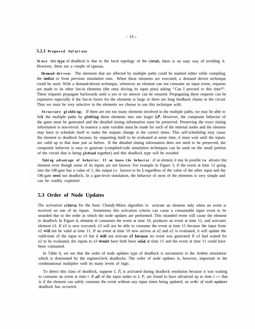
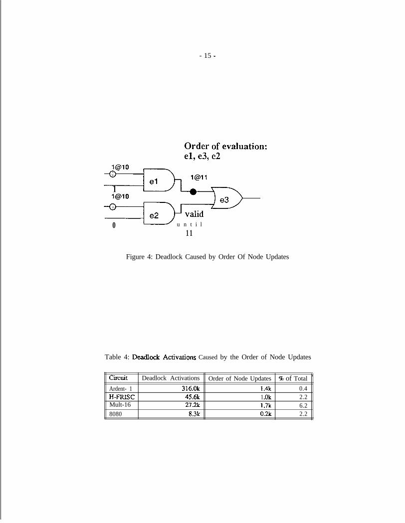
The activation crireria for the basic Chandy-Misra algorithm is: activate an element only when an event isreceived on one of its inputs. Sometimes this activation criteria can cause a consumable input event to bestranded due to the order in which the node updates are performed. This stranded event will cause the elementto deadlock In Figure 4, element el consumes the event at time 10, produces an event at time 11, and activateselement e3. If e3 is now executed, e3 will not be able to consume the event at time 11 because the input frome2 wilI not be valid at time 11. If an event at time 10 now arrives at e2 and e2 is evaluated, it will update thevalid-time of the input to e3 but it will not activate e3 because no event was generated If e3 had waited fore2 to be evaluated, the inputs to e3 would have both been valid at time 11 and the event at time 11 could havebeen consumed.
In Table 6, we see that the order of node updates type of deadlock is uncommon in the Ardent simulationwhich is dominated by the registerclock deadlocks. The order of node updates is, however, important in thecombinational multiplier with its many levels of logic.
To detect this class of deadlock, suppose L Pi is activated during deadlock resolution because it was waitingto consume an event at time 1. If all of the input nodes to L P, are found to have advanced up to time t - thatis if the element can safely consume the event without any input times being updated, an or&r of node up&mdeadlock has occurred.
- 15 -
Order of evaluation:el, e3, e2
0 u u n t i l11
Figure 4: Deadlock Caused by Order Of Node Updates
Table 4: Detadlock Actiwtions Caused by the Order of Node Updates
circuit Deadlock Activations Order of Node Updates % of Total7
Ardent- 1 316.0k 1.4k 0.4H-FRISC 45.6k 1 .Ok 2.2Mult-16 27.2k 1.7k 6.28080 8.3k 0.2k 2.2
- 16 -
53.1 Proposed Solutions
New activation criteria: The problem is that the activation criteria does not activate an element when the validtimes of its input node are updated. The problem can be eliminated if an element checks its fan-out elementswhen it updates the time of its output nodes. Any of those fan-out elements that have a real event at a timeless than or equal to the new valid-time, should be activated. In the example, e2 would activate e3 when itupdated the valid-time of its output to 11 since e3 has a real event at time 11. Note that this only works for thecase where the updated node is directly connected to the element with the unconsumed event. If there are anyintermediate elements the deadlock is considered to be caused by an unevaluated path which is explained in thenext subsection. If e3 had a third input, it still may not be able to consume the event at time 11 even after e2is evaluated This extra activation creates needless work and the effectiveness of this solution depends on therelative cost of performing a deadlock resolution on the particular circuit being simulated.
Rank ordering: The rank of an element is the maximum number of levels of logic between the element andany registers. It can be computed by assigning all registers and generator elements a rank of 0 and then iteratingthrough the combinational elements assigning them a rank of one plus the maximum rank of its input elements.If the elements in the evaluation queue are ordered by their rank, the node updates will proceed in a more orderedfashion (i.e. elements farther away from the registers and external inputs that affect it will be evaluated laterpossibly letting their inputs become defined). In the example, e2 would be inserted before e3 since the inputsto t3 depend on the outputs of e2. Since the rank information is easy to compute while compiling the netlist,the run-time cost is very little. Also, this technique may actually eliminate some extra activations so the overallcost is cheap.
. 5.4 Unevaluated Path
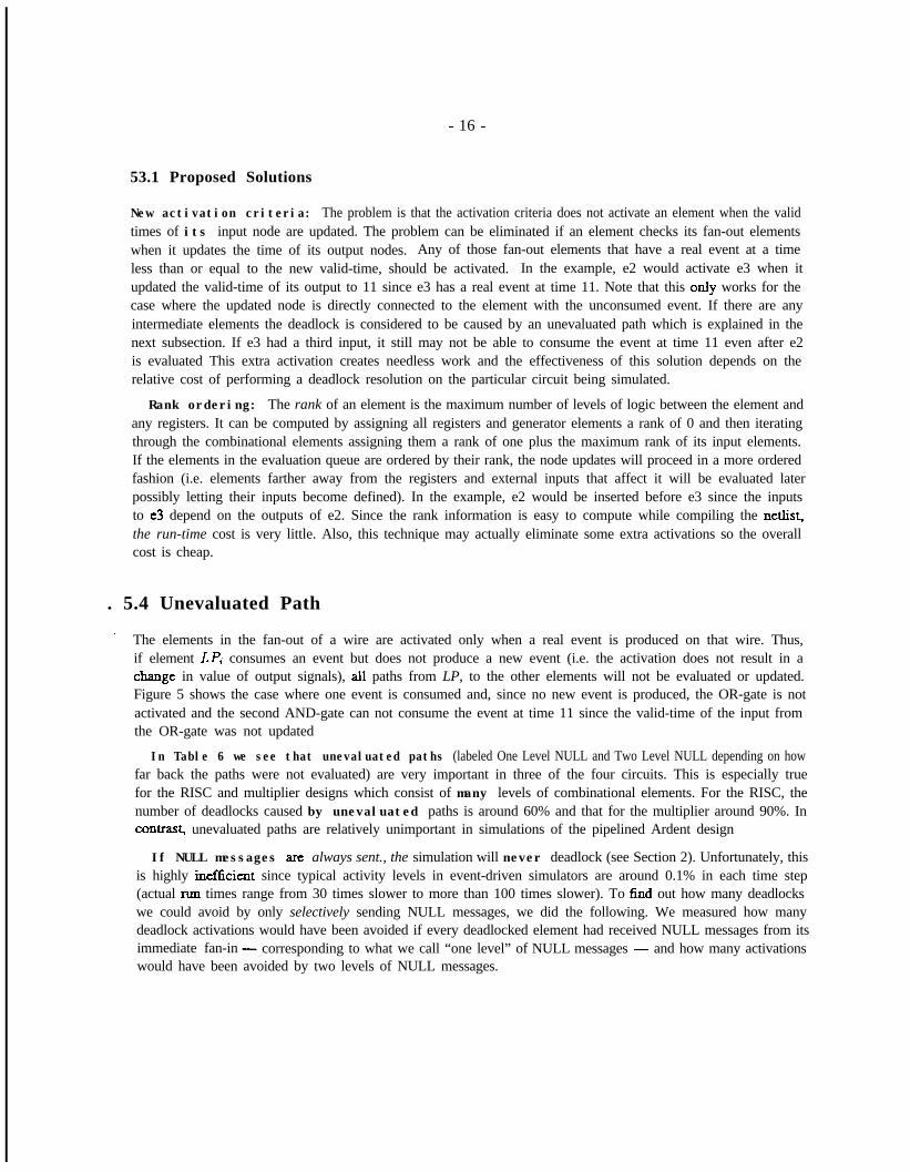
^ The elements in the fan-out of a wire are activated only when a real event is produced on that wire. Thus,if element LPi consumes an event but does not produce a new event (i.e. the activation does not result in achange in value of output signals), all paths from LP, to the other elements will not be evaluated or updated.Figure 5 shows the case where one event is consumed and, since no new event is produced, the OR-gate is notactivated and the second AND-gate can not consume the event at time 11 since the valid-time of the input fromthe OR-gate was not updated
In Table 6 we see that unevaluated paths (labeled One Level NULL and Two Level NULL depending on howfar back the paths were not evaluated) are very important in three of the four circuits. This is especially truefor the RISC and multiplier designs which consist of many levels of combinational elements. For the RISC, thenumber of deadlocks caused by unevaluated paths is around 60% and that for the multiplier around 90%. Incontrasf unevaluated paths are relatively unimportant in simulations of the pipelined Ardent design
If NULL messages arc always sent., the simulation will never deadlock (see Section 2). Unfortunately, thisis highly in&cient since typical activity levels in event-driven simulators are around 0.1% in each time step(actual nm times range from 30 times slower to more than 100 times slower). To find out how many deadlockswe could avoid by only selectively sending NULL messages, we did the following. We measured how manydeadlock activations would have been avoided if every deadlocked element had received NULL messages from itsimmediate fan-in - corresponding to what we call “one level” of NULL messages - and how many activationswould have been avoided by two levels of NULL messages.
- 17 -
no event
Figure 5: Deadlock Caused by Unevaluated Path
Table 5: Deadlock Activations Caused by Unevaluated Paths
-I
c i r c u i t Deadlock O n e % o f Two % of CombinedActivations Level Total Level Total %
Ardent-l 308.Ok 81.9k 26 221.9k 72.0 9 8H-FRISC 45.8k 35.7k 78 1.2k 2.6 81Muit- 27.2k 21.6k 79 1.6k 5.9 858080 83k 2.6k 32 0.9k 105 42
- 18 -
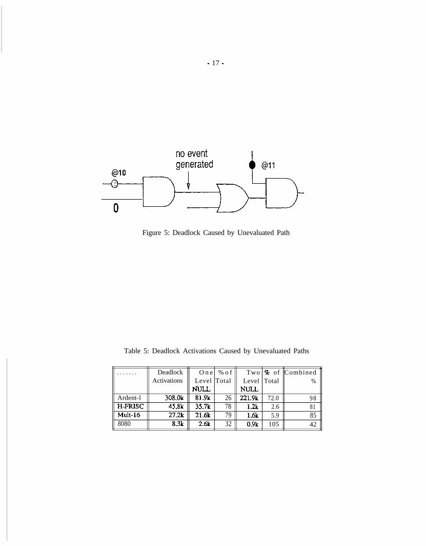
Table 6: Deadlock Activations Classified by Type
circuit Total Reg-clk Generator Order of One Level Two Level UnaccountedDeadlock Actv. Actv. Node NULL
Activations3 updatesArdent-l 308.0k 280.8k 0.8k 1.6k 81.9k 221.9k 543RISC 45.8k 8.9k 8.9k 1.2k 35.7k 12% 0Mult 23.4k O.Ok O-Ok 1.6k 21.6k 1.6k 2888080 . 8.3k 4.6k 4.6k 0.2k 2.6k 0.9k 265
54.1 Proposed Solutions
Caching: Since the activity levels are so low, we need to be very selective about which elements should sendNULL messages. The proposed selection process follows the concept of caching. By caching information fromprevious runs, we can identify the elements that repeatedly deadlock due to an unevaluated path as the simulationprogresses. When these elements get activated, they wiIl send out NULL messages whenever their outputs timesadvance. In order to be effective, the caching algorithm must be quick and efficient.
Taking advantage of behavior: See Section 52.1 for a description. As it turns out, this technique worksvery well for the combinational multiplier circuit. It eliminates all deadlocks and increases the parallelism from45 to 160.
5.5 Summary of the Contributions From Each Deadlock Type
A summary of the composition of deadlocks for the benchmark circuits is given in Table 6. In all but the Ardentand 8080 circuits, the main deadlock type is the one-level NULL caused by unevaluated paths which are, inturn, caused by the very low activity levels in digital logic simulations. The Ardent and 8080 deadlocks aremade up predominan tIy of register-clock deadlocks. They account for 91% and 55% of the deadlock activations,respectively, even though synchronous elements comprise only 11 to 17% of the total elements. This is mainlydue to the heavily pipelined nature of the two circuits - many of latches with only a few levels of logic inbetween. Thus most of the deadlocks occur when the registers and latches are waiting for their inputs to becomevalid.
The main contributors to deadlock in the RISC circuit, after the one-level NULL deadlocks, are generator andregisterclock deadlocks. This is due to the consistent control style used by the synthesis system. The systemclocks are generated wtema.lly and first pass through a level of logic that controls which parts of the design areactive. These qualified clocks are then distributed to their corresponding circuit sections - the result being thatmost registers are waiting on their inputs and the elements connected to the generator nodes are waiting on theirother inputs.
In COnbrast to the other three circuits, the muhiplier design is highly interconnected with many levels ofcombinational logic. Almost all of the deadlock activations are caused by the unevaluated paths in the circuit asshown by the two-level NULL column This is caused by a few paths that are active all the way from the inputsto the outputs while most of the paths do not have any activity at all after the first couple of levels.
3Each activation may have more than one cause so the sum of the deadlock activation types may be more than the total.

- 19 -
6 Preliminary Results
With the classifications of deadlock types presented in the previous section, we are now ready to evaluate theeffectiveness of the proposed solutions for avoiding deadlock The results and analysis presented in this sectionare a collection of the preliminary results we have obtained. Wherever possible, these results are related toaspects of the circuit being simulated or effects particular to digital logic simulation. The structure of this sectionis as follows. We first present speed-up curves for the event-driven algorithm and Chandy-Misra algorithm ona simulated 60-processor machine. Next, we quantify the overheads incurred by the Chandy-Misra algorithmin relation to the event-driven algorithm. Then we compare the achieved concurrency versus the maximumconcurrency as determined by the event distribution and structure of the circuit We then detail how we takeadvantage of element behavior and how effective it is in reducing execution times and deadlock activations.Finally we give results on the effectiveness of a one-level demand driven scheme and a global event countingscheme.
6.1 Speed-up Curves
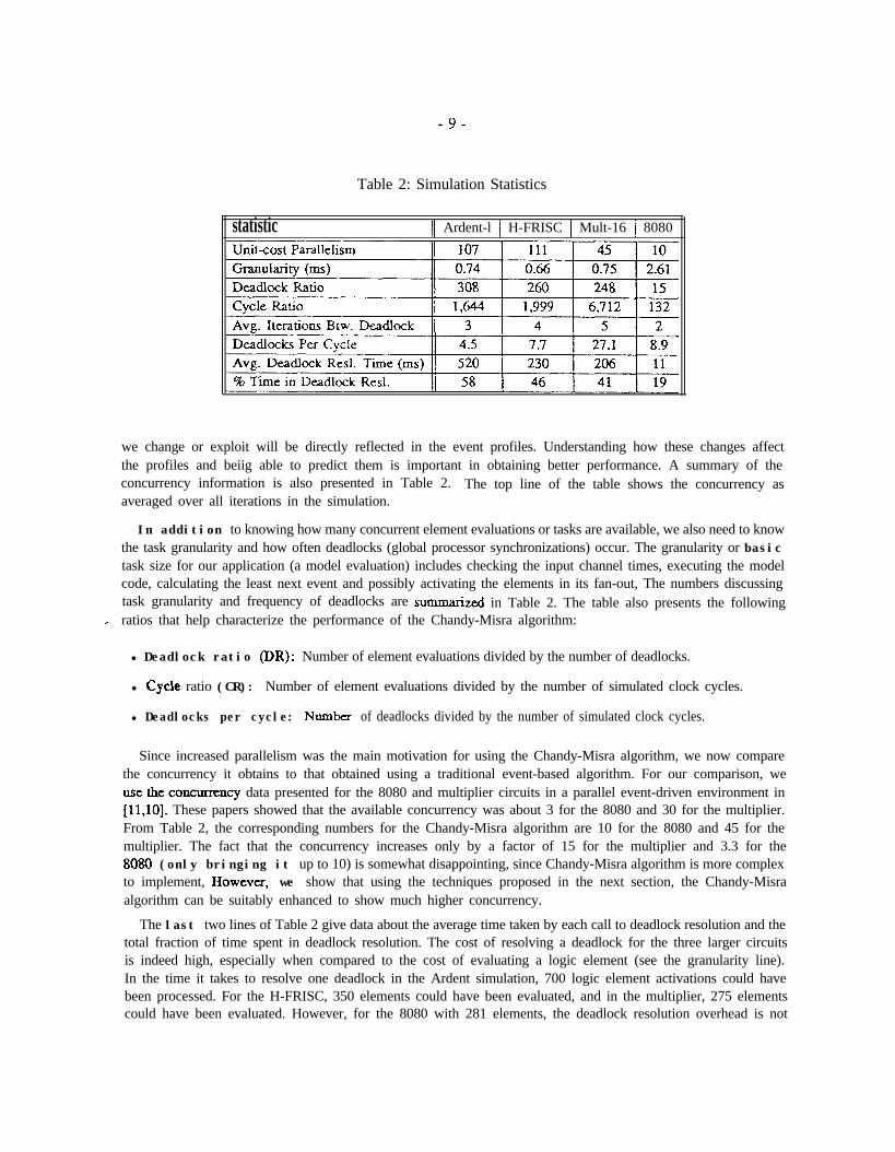
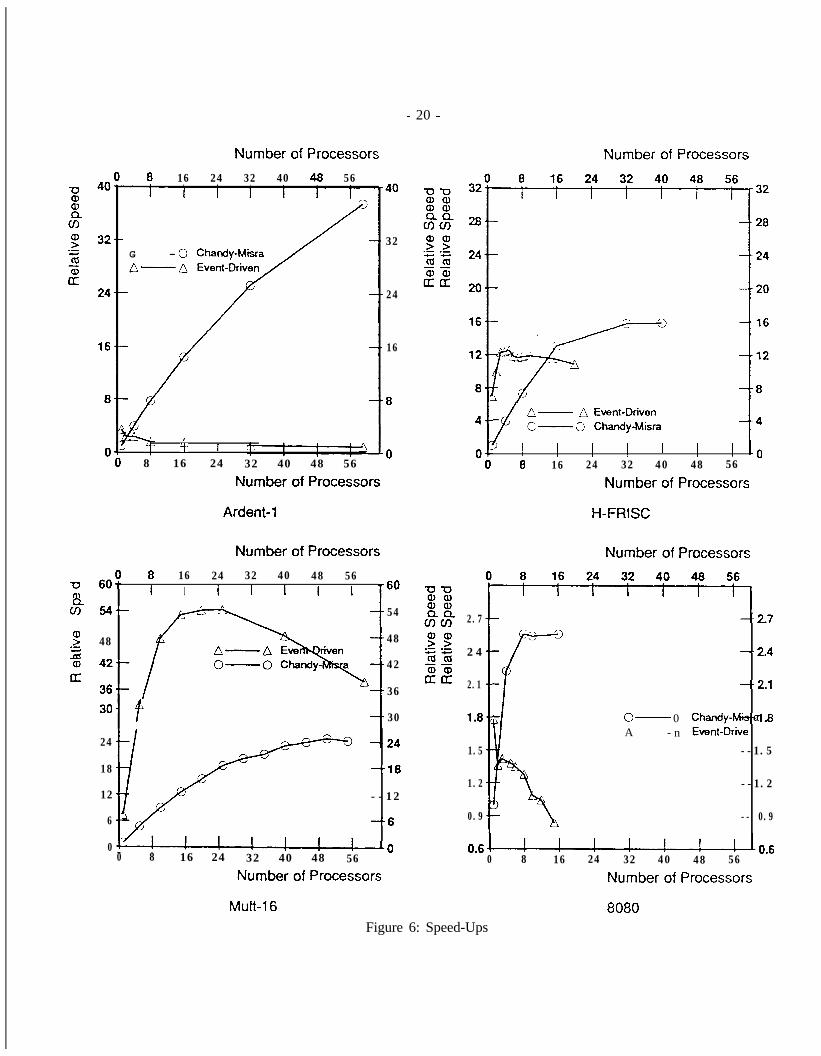
The first step in analyzing the Chandy-Misra algorithm and the various optimizations is to see how the idealconcurrency presented earlier translates into actual parallel performance and how this performance compares tothe parallel performance of the event-driven algorithm. This comparison is done with the help of the speed-up curves presented Figure 6. The four speed-up curves compare the generic Chandy-Misra implementationwith an eventdriven simulator described in [ll]. The “Relative Speed” axis on each plot is normalized tothe generic Chandy-Misra algorithm nxrning on one processor. The simulations were done using Tango[q, a
* simulated multiprocessor environment described in detail in Section 3.3.1. The results for each circuit will nowbe discussed in turn.
The Ardent-l simulation shows the most favorable performance comparison for the Chandy-Misra algorithmover the event-driven algorithm. Although the uniprocessor Chandy-Misra performs only about one-third as fastas the event driven algortihm, the Chandy-Misra algorithm exceeds the best event-driven performance when fouror more processors are used. Furthermore, the Chandy-Misra algorithm achieves a relative speed around 37 with60 processors while the event-driven algorithms best speed is only 3.5. The poor performance of the eventdrivenalgorithm is due to the distribution of the events across simulation time. A typical clock cycle consists of oneor two time-steps with around 1000 events and about thirty time-steps with l-10 events. Since the event-drivenalgorithm is forced to only look at one time-step at a time, the thirty or so time-steps with only l-10 events rumthe parallel performance (recall that each time-step also causes a global synchronization of all the processors).Thus, the event-driven algorithm is unable to exploit most of the parallelism uncovered by the Chandy-Misraalgorithm.
For the H-FRISC circuit, the pexformanc e for the event-driven algorithm starts out about six times faster thanthe Chandy-Misra algorithm and gets good speed-ups up to four processors. With more than four processors, theglobal synchronization of the processors at every time-step and low number of events in each time-step limitsthe performance to about 13 relative to the Chandy-Misra algorithm. Even though the Chandy-Misra starts atabout one-sixth the speed of the event-driven, it gets relatively good speed ups up to 24 processors, crossingthe event-driven performance at about 16 processors. W&h 32 processors, the Chandy-Misra algorithm performs3040% better than the best event-driven performance.
The Mu-h-16 simulation shows the most favorable results for the event-driven algorithm with its best parallelperformance achieving about twice the relative speed of the best parallel performance of the Chandy-Misraalgorithm. The event-driven relative performance tops out at 54 with 24 processors. With more than 24
- 20 -
Number of Processors Number of Processors8 16 24 32 40 48 56
32
24
16
G - O Chandy-MisraA-A Event-Driven
;/
A- A Event-Driven-i C-0 Chandy-Misra
r3- 1 I: ! ! ! ! I ! ! 10
8 16 24 32 40 48 560 8 16 24 32 40 48 56Number of Processors Number of Processors
Ardent-l H-FRISC
Number of Processors Number of Processors
6Oy8 16 24 32 40 48 56
0E
1 I I I I I I T60
2- 54.-
F 48.-zii.5 42.-u
36.-
54
48
42
36
30- f 30
24
18
12
6
0
---18
--12
---6
2.7
24
2.1
1.8
1.5
1.2
0.9
---2.7
-- 2.4
--221
chandy-MistKlsEvent-Drive
--1.5
--1.2
-- 0.9
O- 0A - n
0 8 16 24 32 40 48 56Number of Processors
0.6~0'60 8 16 24 32 40 48 56
Number of Processors
Mult-16 8080Figure 6: Speed-Ups

-2l-
processors, there are not enough available concurrent events relative to the cost of synchronizing and loadimbalance. The poor Chandy-Mism performance, reaching 24 with 48 processors, is due to the large numberof deadlocks that cause global processor synchronization (there are about 27 deadlocks per cycle - Section 6.4shows how all deadlocks in this simulation can be eliminated allowing the Chandy-Misra algorithm to performtwice as fast as the event driven algorithm).
For the 8080, both algorithms perform poorly. The event-driven algorithm starts out about twice as fast butachieves no speed-up with added processors. The Chandy-Misra algorithm achieves a 2.5 fold speed-up with8 processors and not much more as more processors are added. The reason for the poor performance for bothimplementations is the very low number of elements. The 8080 circuit only has 281 elements - there just isn’tmuch to work with.
6.2 Overheads in the Chandy-Misra and Event-Driven Algorithms
In the preceeding section, we observed that on a uniprocessor, the event-driven algorithm is roughly 2-6 timesfaster than the Chandy-Misra algorithm for the four circuits. This performance penalty is very large and, forthe Chandy-Misra algorithm to be practical, it must be reduced significantly. We are currently working on waysof reducing this overhead and have found that it consists of three components: deadlock resolution time, morecomplex element evaluations, and extra element evaluations. The contribution of each of these componentsis detailed in Table 7. We see that in the larger circuits, deadlock resolution accounts for 4060% of thetotal execution time. This alone causes a 2-fold slowdown over the event-driven algorithm. Secondly, eachelement evaluation is more complex than in an event-driven scheme. Both algorithms must compute the elementbehavior, but the Chandy-hGsra algorithm must also compute which input events can be consumed during thecurrent evaluation. Table 7 shows that the average element evaluation in the Chandy-Misra environment takesabout 86% longer than the corresponding evaluation in an event-driven environment. The last component ofoverhead is an average of 26% more element evaluations. As an example of how these extra evaluations occur,consider an AND-gate receiving an event at time 10. This event will cause the gate to be scheduled for evaluation.However, suppose this event can not consumed by the gate due to another of the gates inputs lagging behind insimulation time. The gate must then either wait for deadlock resolution to advance all nodes to time 10 or waitfor another event to arrive on one of its inputs. In either case, the original evaluation (caused by the receipt ofthe event at time 10) did not consume any events or advance the local time of the AND-gate. This event at time1ocallonlybeconswIl ed later by a second evaluation. In the eventdriven algorithm, only one evaluation wouldhave been necessary. These extra evaluations combined with the longer evaluation tunes and the overhead fordeadlock resolution cause the Chandy-Misra to execute 2-6 times slower on a uniprocessor. This overhead mustbe reduced in order to make the Chandy-Misra algorithm suitable for use with small-scale parallel systems. Weare currently looking at several methods to reduce each of three types of overheads including better activationcriteria, exploiting more domain specific knowledge about element behavior, and caching schemes in deadlockresolution.
6.3 Maximum Parallelism Available From This Approach
Since the Chandy-Misra algorithm executes 2-6 times slower than the event-driven algorithm on a uniprocessor,the Chandy-Misra algorithm had better uncover significantly more concurrency in order to be effective. Earlier,we showed that the Chandy-Misra algorithm achieved an average concurrency of 68 for the four benchmarkcircuits. To see just how much this concurrency can be increased, we performed simulation runs that computedthe maximum amount of exploitable concurrency constrained only by the distributed-time method itself, regardlessof the parti~ti choices of activation cirteria, deadlock resolution scheme, or parallel architecture used. The

- 22 -
Table 7: Overheads in the Chandy-Misra Algorithm
Element Evaluations Grain Size (Simulated Cycles) % Time InC-M [ Event-Driven C-M 1 Event-Driven Deadlock Resolution
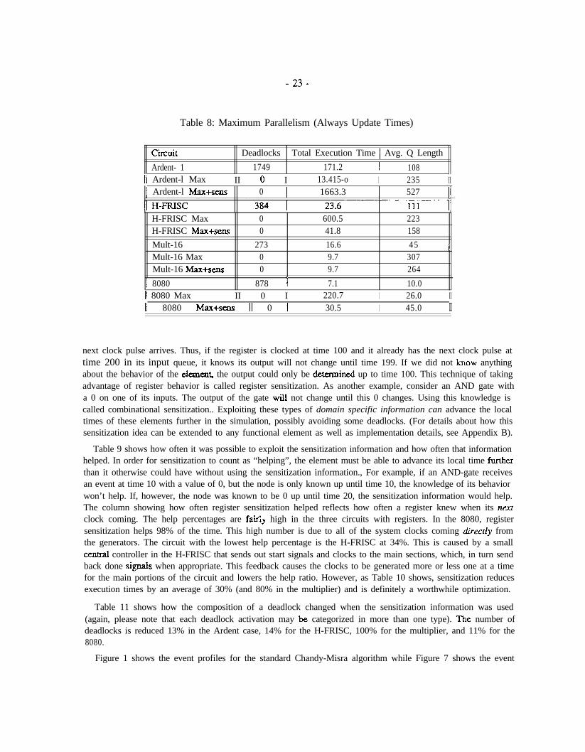
maximum concurrency that can be exploited by an event-based simulator depends on the dynamic dependenciesbetween the unprocessed events in the circuit, the topology of the circuit, and the behavior of the circuit. Thedependencies change as events are processed and new events are produced. Since the Chandy-Misra algorithmonly activates elements when an event arrives on one of its inputs and does not always propagate time updates, itdoes not extract the maximal concurrency; in order to find out what this maximum concurrency is, each elementevaluation that updates the valid-time of a wire, must propagate the effects of that update forward through thecircuit (this is similar to having every element send a NULL message after every evaluation as described inSection 2). The simulation execution times are very long with this “maximum propagation** turned on, but theresults are instructive. The average Q lengths obtained from these simulations show the maximum availableconcurrency constrained only by the dynamic interaction of the events in the system and the topology of thecircuit. Table 8 presents data showing how the concurrency and uni-processor run times are affected by this
. “ m a x i m u m propagation”. The average Q length in the “Max” runs represent the maximal concurrency. The“Max+sens” runs show how knowledge of the element behavior (sensitization) dramatically reduces the timetaken for deadlock avoidance (though still high when compared with deadlock detection) while still achievinghigh parallelism. Note that the Q lengths for the “Max+sens” runs can be greater than the “Max” runs, as they arefor the Ardent and 8080 circuits. The reason that sensitization can extract more than the “maximal” concurrencyis that incorporating element behavior into the simulation changes the behavior of the simulation.
Table 8 shows that for the Ardent-l, H-FRISC, and 8080 circuits, the generic Chandy-Mism algorithm extractsabout 40-50% of the maximum concurrency as constrained by the dynamic event distribution and topology of thecircuit For the Mult-16 circuit, the Chandy-Misra algorithm extracts only 15% of the maximum concurrency.This is much lower than the simulations of the other three circuits due to the high incidence of deadlock. Sincethere are 20 deadlocks per clock cycle in the multiplier simulations and the evaluation queue length must dwindledown to zero before each deadlock is detected, the average queue length is cut down to 15% of maximum. Thus,the generic Chandy-Misra algorithm exploits an average concurrency of 68. This concurrency is 34% of themaximal average concurrency of 198. However, if we change the simulation by introducing knowledge of thebehavior of some of the elements, the maximal average concurrency is increased to 249 and the concurrencyexploited by the Chandy-Misra is increased to 93 or 37% of maximal. In either case, the Chandy-Misra algorithmeffectively exploits a good portion of the actual concurrency present in the logic simulations.
6.4 Exploiting Element Behavior
In general, an element can safely advance its local time only when all of its inputs are ready. However, forsome types of elements it is known that the outputs will be stable for a certain period of time regardless of someof the other inputs. For example, for some simple registers, it is known the output will not change until the
- 23 -
Table 8: Maximum Parallelism (Always Update Times)
circuit Deadlocks Total Execution Time 1 Avg. Q LengthArdent- 1 1749 171.2 I 108
11 Ardent-l Max II 0 I 13.415-o I 235 II1 Ardent-l Max+sens 0 1663.3 527 I
vH-FRISC Max 0 600.5 223H-FRISC Max+sens 0 41.8 158Mult-16 273 16.6 4 5 1Mult-16 Max 0 9.7 307Mult-16 Max+sens 0 9.7 264
1 8080 878 I 7.1 10.011 8080 Max II 0 I 220.7 I 26.0 IItl 8080 Max+sens 11 0 1 30.5 I 45.0 II
next clock pulse arrives. Thus, if the register is clocked at time 100 and it already has the next clock pulse attime 200 in its input queue, it knows its output will not change until time 199. If we did not know anythingabout the behavior of the element, the output could only be detamined up to time 100. This technique of takingadvantage of register behavior is called register sensitization. As another example, consider an AND gate witha 0 on one of its inputs. The output of the gate wilI not change until this 0 changes. Using this knowledge iscalled combinational sensitization.. Exploiting these types of domain specific information can advance the localtimes of these elements further in the simulation, possibly avoiding some deadlocks. (For details about how thissensitization idea can be extended to any functional element as well as implementation details, see Appendix B).
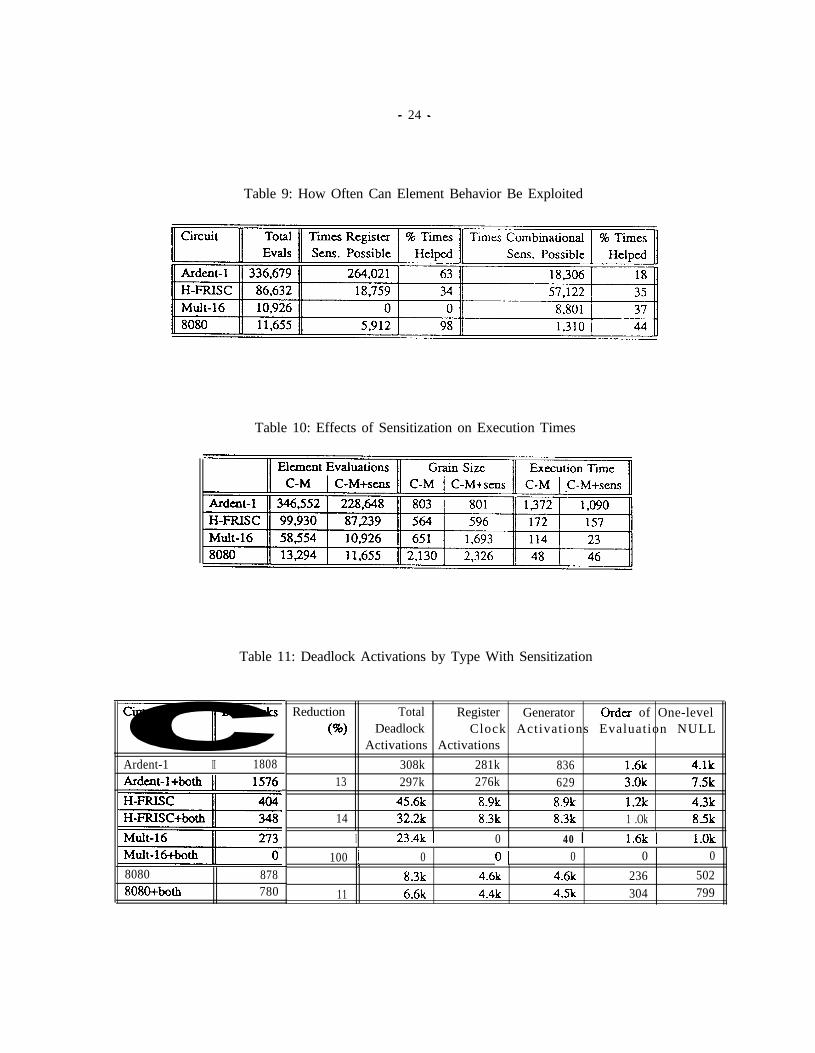
Table 9 shows how often it was possible to exploit the sensitization information and how often that informationhelped. In order for sensitization to count as “helping”, the element must be able to advance its local time furtherthan it otherwise could have without using the sensitization information., For example, if an AND-gate receivesan event at time 10 with a value of 0, but the node is only known up until time 10, the knowledge of its behaviorwon’t help. If, however, the node was known to be 0 up until time 20, the sensitization information would help.The column showing how often register sensitization helped reflects how often a register knew when its nextclock coming. The help percentages are fairly high in the three circuits with registers. In the 8080, registersensitization helps 98% of the time. This high number is due to all of the system clocks coming directZy fromthe generators. The circuit with the lowest help percentage is the H-FRISC at 34%. This is caused by a smallcentral controller in the H-FRISC that sends out start signals and clocks to the main sections, which, in turn sendback done signaIs when appropriate. This feedback causes the clocks to be generated more or less one at a timefor the main portions of the circuit and lowers the help ratio. However, as Table 10 shows, sensitization reducesexecution times by an average of 30% (and 80% in the multiplier) and is definitely a worthwhile optimization.
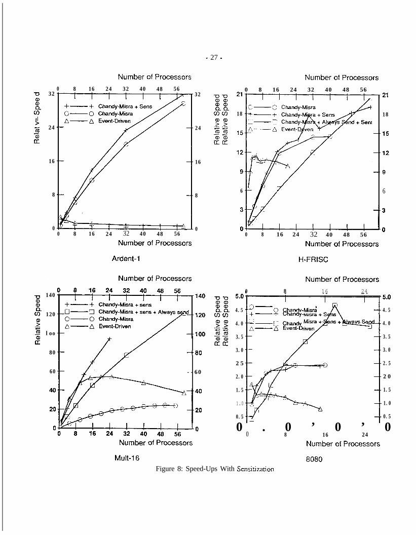
Table 11 shows how the composition of a deadlock changed when the sensitization information was used(again, please note that each deadlock activation may be categorized in more than one type). The number ofdeadlocks is reduced 13% in the Ardent case, 14% for the H-FRISC, 100% for the multiplier, and 11% for the8080.
Figure 1 shows the event profiles for the standard Chandy-Misra algorithm while Figure 7 shows the event
- 24 -
Table 9: How Often Can Element Behavior Be Exploited
Table 10: Effects of Sensitization on Execution Times
Table 11: Deadlock Activations by Type With Sensitization
Ardent-1 II 1808Ardmt-l+both
8080 878808O+both 780
Reduction Total Register Generator Order of One-level(W Deadlock Clock Activations Evaluation NULL
Activations Activations308k 281k 836 1.6k 4,lk
13 297k 276k 629 3.0k 7Sk45.6k 8.9k 8.9k 1.2k 4.3k
14 32.2k 8.3k 8.3k 1 .Ok 8.5kI 23.4k 1 0 40 I 1.6k I l.Ok
100 1 0 01 0 0 0
8.3k 4.6k 4.6k 236 50211 6.6k 4.4k 4.5k 304 799
-25-
profiles for the Chandy-Misra algorithm using sensitization information (the multiplier plot is not included sincethere were no deadlocks - a plot of the parallelism and activations per deadlock would be uninteresting). Thereis not too much difference, again excluding the multiplier circuit, in the appearance of the two sets of profiles.
Figure 8 shows the relative parallel for the Chandy-Misra algorithm with and without sensitizationinformation.
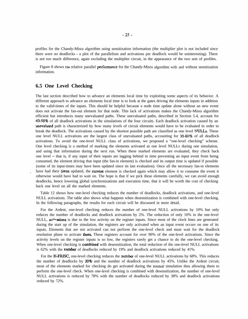
6.5 One Level Checking
The last section described how to advance an elements local time by exploiting some aspects of its behavior. Adifferent approach to advance an elements local time is to look at the gates driving the elements inputs in additionto the valid-times of the inputs. This should be helpful because a node time update alone without an new eventdoes not activate the fan-out element for that node. This lack of activations makes the Chandy-Misra algorithmefficient but introduces many unevaluated paths. These unevaluated paths, described in Section 5.4, account for40-98% of all deadlock activations in the simulations of the four circuits. Each deadlock activation caused by anunevaluted path is characterized by how many levels of circuit elements would have to be evaluated in order tobreak the deadlock. The activations caused by the shortest possible path are classified as one level NULLS. Theseone level NULL activations are the largest class of unevaluated paths, accounting for 30-80% of all deadlockactivations. To avoid the one-level NULL class of activations, we proposed a “one-level checking” scheme.One level checking is a method of marking the elements activated as one level NULLS during one simulation,and using that information during the next run. When these marked elements are evaluated, they check backone level - that is, if any input of their inputs are lagging behind in time preventing an input event from beingconsumed, the element driving that input (the fan-in element) is checked and its output time is updated if possible(some of its input-times may have been updated since its last evaluation). Once all the necessary fan-m elements
_ have had their times updated, the cument element is checked again which may allow it to consume the event itotherwise would have had to wait on. The hope is that if we pick these elements carefully, we can avoid enoughdeadlocks, hence lowering global synchronizations and execution time, that it will be worth the cost of checkingback one level on all the marked elements.
Table 12 shows how one-level checking reduces the number of deadlocks, deadlock activations, and one-levelNULL activations. The table also shows what happens when desensitization is combined with one-level checking.In the following paragraphs, the results for each circuit will be discussed in more detail.
For the Ardent, one-level checking reduces the number of one-level NULL activations by 10% but onlyreduces the number of deadlocks and deadlock activations by 2%. The reduction of only 10% in the one-levelNULL, activations is due to the low activity on the register inputs. Since most of the clock lines are generatedduring the start up of the simulation, the registers are only activated when an input event occurs on one of itsinputs. Elements that are not activated can not perform the one-level check and must wait for the deadlockresolution phase to activate them. These registers account for over 90% of the one-level activations. Since theactivity levels on the register inputs is so low, the registers rarely get a chance to do the one-level checking.When one-level checking is cornbind with desensitization, the total reduction of the one-level NULL activationsis 62% with the munbcr of deadlocks reduced by 19% and deadlock activations reduced by 41%.
For the H-FRISC, one-level checking reduces the number of one-level NULL activations by 68%. This reducesthe number of deadlocks by 20% and the number of deadlock activations by 45%. Unlike the Ardent circuit,most of the elements marked for checking do get activated during the normal simulation thus allowing them toperform the one-level check. When one-level checking is combined with desensitization, the number of one-levelNULL activations is reduced by 78% with the number of deadlocks reduced by 38% and deadlock activationsreduced by 72%.

800
600
400
200
0 i1200 1230 1260 1290 1320 1350 1380
Iteration
Ardent Queue Len9t.h Profile
800
600
400
200
070 110 150 190 230 270 310 350
6teration
H-FRISC Queue Length Profile
80
60
40
20
0430 450 470 490 510 530 550
tteration
8080 Queue Length Profile
Figure 7: Event Profiles With Sensitization
- 27 -
Number of Processors Number of Processors0 8
3216 24 32 40 48 56
-0ii8-al>.-3
24
E
16
8
00 8 16 24 32 40 48 56
Number of Processors
u 140iiic?- 120P.-3 loo2
80
60
Ardent- 1 H-FRISC
Number of Processors Number of Processors
32
24
16
8
0
---80
--60
Number of Processors
18
6
0 8 16 24 32 40 48 56
0 8 16 24 32 40 48 56Number of Processors
0 8 16 24
18
6
4.5
4.0
3.5
3.0
2 5
2.0
1.5
1.0
0.5
-0 Chandy-Misra
-+ chandy-
-----Cl Chandy-A Event-D
4.5
4.0
3.5
3.0
2.5
20
1.5
1.0
0.5
0 . 0 ’ 0 ’ 00 8 16 24
Number of Processors
Mutt-l 6 8080Figure 8: Speed-Ups With Sensitiztion
-2a-
Table 12: Deadlock Activations With One Level Checking - Part 1
circuit D e a d l o c k s % D e a d l o c k % One % ExecutionRedct. Actv. Redct Level Redct Tie
1 NULL
Ardent-l 1749 306.0k 80.3k 1372Ardent- 1 +Chk 1710 2.2 299.3k 2-2 72.0k 10.3 1539Ardent- I +Sens 1512 13.6 197.8k 35.3 45.4k 1090Ardent-l+Chk+Sens 1406 19.1 181.8k 40.6 30.8k 61.6H-FRISC 384 45.8k 35.7k I72H-FRISC+Chlc 307 20.0 25.lk 45.2 115k 67.8 168H-FRISC+Sens 327 14.8 32.3k 29.5 23.2k 157
11 H-FRISC+Chlc+Sens 11 236- -1 38.5 13.6k 70.3 7.7k 78.4 137I 1 II I I, 0
Mull-16 I! 273 11 27.2k ] 11 21.6k 1 115- _- I !!R
I[ Mult-16Khk II 269 1 1.5 11 104k I 61.8 II 6.8k 1 68.5 11 126 IIn Mult-16+Sens II 0 I 100.0 II 0 I 100.0 II 0 I II 23 n11 Mult-16+Chk+Sen.s 11 0 1 100.0 11 c IlOO.OtI 0 I 11 23 11
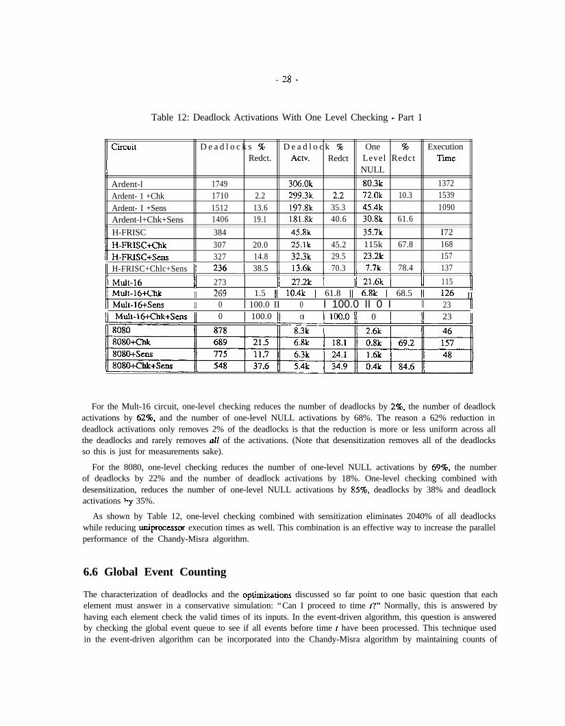
For the Mult-16 circuit, one-level checking reduces the number of deadlocks by 2%. the number of deadlockactivations by 62%~~ and the number of one-level NULL activations by 68%. The reason a 62% reduction indeadlock activations only removes 2% of the deadlocks is that the reduction is more or less uniform across allthe deadlocks and rarely removes all of the activations. (Note that desensitization removes all of the deadlocksso this is just for measurements sake).
For the 8080, one-level checking reduces the number of one-level NULL activations by 69%, the numberof deadlocks by 22% and the number of deadlock activations by 18%. One-level checking combined withdesensitization, reduces the number of one-level NULL activations by 85%, deadlocks by 38% and deadlockactivations hy 35%.
As shown by Table 12, one-level checking combined with sensitization eliminates 2040% of all deadlockswhile reducing uniprocessor execution times as well. This combination is an effective way to increase the parallelperformance of the Chandy-Misra algorithm.
6.6 Global Event Counting
The characterization of deadlocks and the optimizations discussed so far point to one basic question that eachelement must answer in a conservative simulation: “Can I proceed to time t?” Normally, this is answered byhaving each element check the valid times of its inputs. In the event-driven algorithm, this question is answeredby checking the global event queue to see if all events before time z have been processed. This technique usedin the event-driven algorithm can be incorporated into the Chandy-Misra algorithm by maintaining counts of

- 29 -
Table 13: Deadlock Activations With Cycle Counting
c i r c u i t
Ardent-l
P
Deadlocks % Deadlock % Avg QueueReduction Activations Reduction Length
I 1749 11 306.0k 108II Ardent-l+Count II 1350 I 22.9 11 305.4k 1 0.2 11 122 II
H-FRISC 384 45.8k 111H-FRISCiCount 335 12.8 36.7k 19.9 104Mult-16 273 23.4k 4 5Mult-16iCount 272 0.4 23.4k 0 4 5
4. I II i
8080 878 8.3k 10.0808O+Count 733 16.5 4.4k 47.0 9.3
the unprocessed events in the system with event-times below some time t. Unfortunately, keeping counts of theevents left at each time-step would cause serious bottlenecks at the counter locks. To avoid these bottlenecks,we decided to keep a counter of the events left in each clock cycle. When the number of events reaches 0 forthis clock cycle, the valid times for all nodes can be implicitly updated to the beginning of the next clock cycle.This allows elements to start consuming events in the next clock cycle thus eliminating one deadlock per clockcycle. Table 13 presents a performance summary of this technique. Since it removes one deadlock per clockcycle, the reduction in the number of deadlocks depends only on the number of deadlocks per cycle.
.. 6.7 Deadlock Avoidance by Always Sending NULLS
As pointed out in Section 6.3, one way to completely avoid deadlocks is to always send out a NULL messageafter every element evaluation. Unfortunately, when used in digital logic simulations, this causes a flood ofNULL messages and simulation times increase 10 or lOO-fold. However, if we use sensitization information inconjunction with always sending NULLs, the simulation times become reasonable and the exploited concurrencyincreases about lo-fold. The speed-up cures in Figure 8 show some very preliminary results for the Chandy-Misra algorithm using this “Always Send+Sens” technique. For the H-FRISC and 8080 circuits, always sendinga NULL message achieves the best overall performance on a 60-processor machine. However, the Ardentsimulation using this technique did not finish after 8 hours of simulation (typical runs were around lo-15minutes) and for the circuits it did work on, large numbers of processors were needed to outperform the othervariants of the Chandy-Misra algorithm. These results are prehminary but we feel the limited success warrantsfurther study into this optimization.
7 ConclusionsIn characterizing the parallelism in distributed-time simulations of real circuits, we have shown that the Chandy-Misra algorithm extracts an average parallelism of 68 for the four benchmark circuits used. While this is 1.5 timesbetter than traditional parallel event-driven algorithms, it is still too low to be used effectively in large parallelprocessing systems. Since deadlocks are the major factor limiting parallelism and the overall performance, thepaper focused on understanding the nature of deadlocks. We classify the deadlocks that occur in logic simulationinto four types: register clocks and generator nodes, multiple paths, unevaluated paths and the order of node
- 30 -
Table 14: Best Performance on a 60 Processor Machine (Times for each circuit are normalized to theChandy-Misra performance on 1 processor)
Circuit Event-Driven Chandy-Misra Chandy-Misra Ratio of Best CM to EV rlWith Optimizations
Ardent-l 35 375 40.2 11.4H-FRISC 12.6 15.9 22.5 1.8Mult-16 54.3 24.4 121.8 2.2
8080 1.7 2.6 4.9 2.9
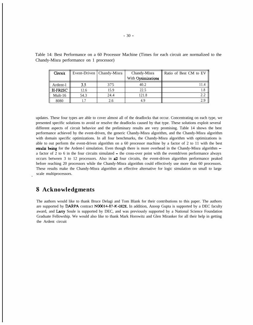
updates. These four types are able to cover almost all of the deadlocks that occur. Concentrating on each type, wepresented specific solutions to avoid or resolve the deadlocks caused by that type. These solutions exploit severaldifferent aspects of circuit behavior and the preliminary results are very promising. Table 14 shows the bestperformance achieved by the event-driven, the generic Chandy-Misra algorithm, and the Chandy-Misra algorithmwith domain specific optimizations. In all four benchmarks, the Chandy-Misra algorithm with optimizations isable to out perform the event-driven algorithm on a 60 processor machine by a factor of 2 to 11 with the bestresuhs beiig for the Ardent-l simulation. Even though there is more overhead in the Chandy-Misra algorithm -a factor of 2 to 6 in the four circuits simulated - the cross-over point with the eventdriven performance alwaysoccurs between 3 to 12 processors. Also in all four circuits, the event-driven algorithm performance peakedbefore reaching 20 processors while the Chandy-Misra algorithm could effectively use more than 60 processors.These results make the Chandy-Misra algorithm an effective alternative for logic simulation on small to largescale multiprocessors.
8 Acknowledgments
The authors would like to thank Bruce Delagi and Tom Blank for their contributions to this paper. The authorsare supported by DARF’A contract NO001487-K-0828. In addition, Anoop Gupta is supported by a DEC facultyaward, and Earry Soule is supported by DEC, and was previously supported by a National Science FoundationGraduate Fellowship. We would also like to thank Mark Horowitz and Glen Miranker for all their help in gettingthe Ardent circuit
- 31 -
References
[l] M. Bailey and L. Snyder. An Empirical Study of On-Chip Parallelism. In 25th Design AutomationConference, pages 160-165. University of Washington, June 1988.
[2] Tom Blank. A Survey of Hardware Accelerators Used in Computer-Aided Design. IEEE Transactions onDesign and Test, pages 21-39, August 1984.
[3] R. E. Bryant Simulation of packet communication architecture computer systems. Technical ReportMIT,LCS,TR-188, MIT, July 1977.
[4] K. M. Chandy and J. Misra. Asynchronous Distributed Simulation Via a Sequence of Parallel Computations.Comm of rhe ACM, 24(11):198-206, April 1981.
(51 Helen Davis and Steven Goldschmidt. Tango: A multiprocessor simulation and tracing system. March1989.
[6] Monty Denneau. The Yorktown Simulation Engine. In 19th Design Atiomation Conference, pages 55-59.ACM/IEEE, 1982.
[7] Tom Diede, Carl Hagenmaier, Glen Miranker, Johnathan Rubinstein, and William Worley. The TitanGraphics Supercomputer Architecture. Computer, 21(9):13-30, September 1988.
{8] David Ku and Giovanni DeMicheli. HERCULES - A System for High-Level Synthesis. In 25th DesignAutomation Conference, pages 483-488. ACM/IEEE, June 1988.
{9] J. Smith, K. Smith, and R. Smith. Faster Architectural Simulation Through Parallelism. In 24rh DesignAutomarion Conference, pages 189-194. ACM/IEEE, June 1987.
[lo] Larry Soule and Tom Blank. Statistics for Parallelism and Abstraction Level in Digital Simulation. InProceedings of the 24th Design Automation Conference, pages 588-591. Stanford University, 1987.
[ll] Larry Soule and Tom Blank. Parallel Logic Simulation on General Purpose Machines. In Proceedings ofthe 2Sth Design Automation Conference, pages 16171. Stanford University, 1988.
[12] Larry Soule and Anoop Gupta. Characterization of Parallelism and Deadlocks in Distributed Digital LogicSimulation. Ia Proceedings of the 26th Design Automation Conference, page Session 7.1. Stanford Univer-sity, 1989.
[13] Steven Swope and Richard Fujimoto. Optimal performance of distributed simulation programs. TechnicalReport UUCS-87-023, University of Utah, Department of Computer Science, 1987.
1141 K. F. Wong, M. A. Franklin, R. D. Chamberlain, and B. L. Shing. Statistics on Logic Simulation. In 23rdDesign Automation Conference, pages 13-19. ACM/IEEE, July 1986.
- 32 -
APPENDICES
A Implementing Inertial Delays
Most commercial event-driven simulators support a more detailed delay model than the one presented here. Thisappendix shows how this approach can be extended to support inertial delays and spike analysis. Figure 9 showthe basic mechanism for implementing inertial delays. The code for the new component, cm-inv looks like:
if (Check cancel input has not changed from the last time we were called){/T We ju% have an event on the normal input */
if (Test == 1){ /* We can always pass falling output transitions */Test b = 0;last-fall = current time;
) else {--
Toggle Check cancel-output;-I
} else {/* Check to see if we should cancel the rising transition on the output
or not */if (last fall -
Test-b = 1;current-time > rise-delay-fall-delay)
- /* It's ok to send out the rising transition */celse
*//* Do nothing since we don't want to send out the rising transition
Since either rising or falling transitions (whichever has the shortest delay) can always be passed through, theycause no degradation in pcrformanc e. The transition type with the longer delay will cause the element to beevaluated twice (once on receiving the input event and once when checking for cancellation). Thus for everycycle ofrisingandfalling transitions we will have tbrcx evaluations whereas we would have two inertial delayswere not impleme.nti, yielding a potential performance degradation of 50%.
B Generalized Sensitization
The previous two sections described how to “desensitize” logic gates and synchronous registers. Since we have avery flexible functional simulator that can use any type of functional element, we want to generalize this conceptof sensitization to work for all functional elements. For example, if a two-input MUX knows the value of itsselect line, it will be able to ignore one of the inputs which may allow it to advance its local time more that ifit were treated as a generic element. This generalized desensitization is represented just like the fixxtionality isrepresented. For the MUX example, there is a routine which determines the values of the outputs based on theinputs just like any functional simulator. There is also a routine which determines the valid times of the outputsbased on the values and valid-times of the inputs. Code for the MUX implementation looks like:
- 33 -
/* Standard functional code */MUX(inputs, select line,- output){
if (select line == 0)-output = inputs[O];
else if (select line == 1)-output = inputs[l];
elseoutput = Undefined; /* select 1- ine is undefined or floating */
/* Timing code *//* "signal" time is the maximum valid time of the */-/* input or the time of the next event on "signal" */MUX-time(inputs, inputs time, select line, select line time, output time) {- - - - -
/* If we know select line is a 0 or a 1, the output is valid until *//* the selected input changes or the select-line changes. */
if (select line == 0)-output time- = Minimum(inputsfime[O], select line time);- -
else if ( select line == 1)-output time =- Minimum(inputs_time[l], select line time);- -
C. /* The output is guaranteed not to change until *//* something happens on the select line */-c
output time = select line time;- - -
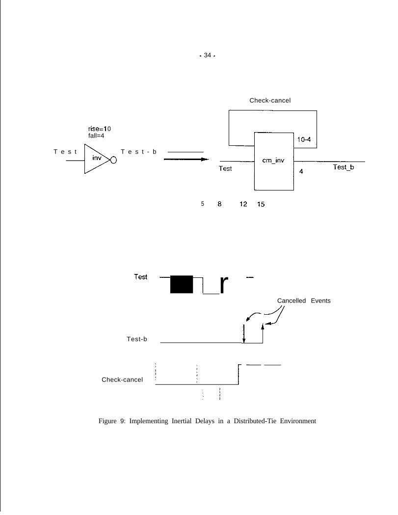
- 34 -
rise=1 0fall=4
T e s t b T e s t - b
5
Test
Check-cancel
rTest-b
Check-cancel_ i [
-
/-
Cancelled Events
1
J
Figure 9: Implementing Inertial Delays in a Distributed-Tie Environment