ANALYSIS OF MULTI-STORIED BUILDING OF VARYING … · Building models with shear walls are developed...
14
DOI:10.23883/IJRTER.2018.4316.CQ4HM 53 ANALYSIS OF MULTI-STORIED BUILDING OF VARYING THICKNESS OF SHEAR WALL ON SLOPING GROUND Ashwin Kumar S V 1 , Ashwini G 2 1 P G Student Department of civil engineering, EWIT, Karnataka, India 2 Assistant Professor, Department of civil engineering, EWIT, Karnataka, India Abstract—This study is to investigate the effect of different thickness of shear wall on sloping ground of multi-storied buildings. Building models with shear walls are developed using ETABS. The location of the shear walls are kept same and a comparative study is done for different thickness of the shear wall for different height of the building. In each of the cases corresponding Investigate is done for the effect of different thickness of shear wall on multi-storied building. Total number of models are considered =16 Thickness of shear wall 5”,10”,15” and 20” are considered Zones to be consider (Zone-II and Zone-V). Height of structure is considered as 10 storey and 15 storey. Keywords—Sloping ground, Seismic forces, Shear wall, RCC Building, Structural analysis, ETABS. I. INTRODUCTION SheareWalls are uniquely composed structuralswalls incorporated in the buildings to restrict horizontal forces that are convey in the plane of the wall due to wind, earthquake and distinctive forces. They are fundamentally flexural members and normally gave in high rise structures to avoid the total fall of the tall structure under the seismic forces. Walls can be designed as plain concrete walls when there is only compression with no tension in the section. else, they should be composed as reinforced concrete walls. The value of the Shear Walls in the confining of structures has sometimes been recognized. At the point when arranged in favourable places of structures, they give an sufficient power to oppose horizontal force resisting system, while at the same time satisfying other functional requirements. For structures up to 20 stories the utilization of shear walls is a decisions matter. For structure is more than 30 stories, shear walls may become basic from view point of economy and avoid of lateral deflection, Because a vast part of side long force on the structure and the lateral shear force usually from it is often assigned to such structural walls is known as “Shear Walls”. Shear walls are behaves like vertical oriented wide beams that conveys earthquake forces downwards to the establishment. That is the reason, it is always suitable to reliable them in structure built in regions likely to earthquake of high amount of intensity or large winds. II. RELATED WORK Sanjay Sengupta (2014) [1] -In this present study investigation done on the effect of varying thick of the shear wall and determining the corresponding percent of reinforcement in varying thicknesssof shearewall. For modelling and analysis developed by using the ETABS with. The position of shear walls are not changed and kept as same and a study they have done by varying thickness of the shear wall for different heights of structure (5 storied, 10 storied and 15 storied). In each cases following requirement reinforcement is found out. It is watched that for a steady thickness of shear divider, support rate increments with increment of the both seismicity and number of storie. It is likewise
Transcript of ANALYSIS OF MULTI-STORIED BUILDING OF VARYING … · Building models with shear walls are developed...
DOI:10.23883/IJRTER.2018.4316.CQ4HM 53
ANALYSIS OF MULTI-STORIED BUILDING OF VARYING
THICKNESS OF SHEAR WALL ON SLOPING GROUND
Ashwin Kumar S V1, Ashwini G2
1P G Student Department of civil engineering, EWIT, Karnataka, India 2Assistant Professor, Department of civil engineering, EWIT, Karnataka, India
Abstract—This study is to investigate the effect of different thickness of shear wall on sloping ground
of multi-storied buildings. Building models with shear walls are developed using ETABS. The location
of the shear walls are kept same and a comparative study is done for different thickness of the shear
wall for different height of the building. In each of the cases corresponding Investigate is done for the
effect of different thickness of shear wall on multi-storied building.
Total number of models are considered =16
Thickness of shear wall 5”,10”,15” and 20” are considered
Zones to be consider (Zone-II and Zone-V).
Height of structure is considered as 10 storey and 15 storey.
Keywords—Sloping ground, Seismic forces, Shear wall, RCC Building, Structural analysis, ETABS.
I. INTRODUCTION SheareWalls are uniquely composed structuralswalls incorporated in the buildings to restrict horizontal
forces that are convey in the plane of the wall due to wind, earthquake and distinctive forces. They are
fundamentally flexural members and normally gave in high rise structures to avoid the total fall of the
tall structure under the seismic forces.
Walls can be designed as plain concrete walls when there is only compression with no tension in the
section. else, they should be composed as reinforced concrete walls.
The value of the Shear Walls in the confining of structures has sometimes been recognized. At the
point when arranged in favourable places of structures, they give an sufficient power to oppose
horizontal force resisting system, while at the same time satisfying other functional requirements. For
structures up to 20 stories the utilization of shear walls is a decisions matter. For structure is more than
30 stories, shear walls may become basic from view point of economy and avoid of lateral deflection,
Because a vast part of side long force on the structure and the lateral shear force usually from it is often
assigned to such structural walls is known as “Shear Walls”.
Shear walls are behaves like vertical oriented wide beams that conveys earthquake forces downwards
to the establishment. That is the reason, it is always suitable to reliable them in structure built in regions
likely to earthquake of high amount of intensity or large winds.
II. RELATED WORK
Sanjay Sengupta (2014)[1] -In this present study investigation done on the effect of varying thick of
the shear wall and determining the corresponding percent of reinforcement in varying thicknesssof
shearewall. For modelling and analysis developed by using the ETABS with. The position of shear
walls are not changed and kept as same and a study they have done by varying thickness of the shear
wall for different heights of structure (5 storied, 10 storied and 15 storied). In each cases following
requirement reinforcement is found out. It is watched that for a steady thickness of shear divider,
support rate increments with increment of the both seismicity and number of storie. It is likewise

International Journal of Recent Trends in Engineering & Research (IJRTER) Volume 04, Issue 06; June - 2018 [ISSN: 2455-1457]
@IJRTER-2018, All Rights Reserved 54
watched that for all the zones, the support rate increments if the shear divider thickness increments for
a specific scope of thickness and after that abatements for a specific scope of thickness. Along these
lines the outcomes demonstrate that expansion of shear divider thickness isn't generally successful for
seismic tremor safe outline.
G.S Hiremath¹, Md Saddam Hussain² (2014)[2] - In the present study, investigation of 25 stories
workinggin zone IV is given some preparatory ivestigation to decrease the impact of quake
strengthened solid shear walls are utilized as a part of the building. These can be utilized for enhancing
seismic reaction of structures. The arrangement of shear walls in working to accomplish unbending
nature has been discovered successful and prudent. Shear dividers are anything but difficult to develop
and are productive, both regarding development cost and viability in limiting seismic tremor harm in
structural and non-basic components (like glass windows and building substance). This investigation
expects to chip away at impact of expansion of shear divider at various area and setup, additionally
think about have been finished with changing thickness of shear divider. The outcomes are arranged
by performing weakling investigation utilizing ETABS v 9.7.1 as relocations and story float.
Varsha R. Harne (2014)[3] - In this paper, accordingly, essential fixation is to choose the response for
shear wall zone in multi-story building. A RCC working of six story set in NAGPUR subjected to
seismic tremor stacking in zone-II is considered. A shudder stack is processed by seismic coefficient
method using IS 1893 (PART– I):2002. These investigation were performed using STAAD Pro. An
examination has been done to choose the nature of RC shear mass of a multi-storeyed working by
changing shear divider territory. Three exceptional occasions of shear divider position for a 6 story
building have been destitute down. Circuit of shear divider has ended up being unavoidable in multi-
story attempting to contradict sidelong powers.
Prasad Ramesh Vaidya (2015)[4] - This examination investigates the seismic execution of shear
divider developing inclining ground. The rule objective is to appreciate the lead of the developing
inclining ground for better places of shear dividers and to think about the ampleness of shear divider
on slanting ground. The execution of building has been considered with the help of four numerical
models. Exhibit one is of edge create essential structure and other three models are of twofold kind
(shear divider plot coordinated effort) fundamental system with three particular spots of shear dividers.
Response extend examination is finished by using restricted segment programming SAP 2000. The
execution of working concerning movement, story coast and most prominent powers in portions has
been displayed in this paper.
S K Hirde and N K Shelar (2015)[5] - In this paper they cleared up about The RCC building models
having G+6 stories with shear dividers and without shear dividers laying on plain and slanting ground
(incline 1V:2.33H) are considered for the examination. The response extend examination of building
is finished using essential outlining programming SAP 2000 V 15.2.2 and the seismic execution of
working with various shear dividers setups is stood out from reverence with parameters like base shear,
level movement, day and age and part controls.
S. Swathi , G.V. Rama Rao, R. A. B. Depaa (2015)[6] - In uneven domains structures depend on
inclining grounds. Exactly when the inclining areas go under the seismic zones, these structures are
significantly vulnerable against tremors. This is a direct result of the way that the areas in the ground
story are of different statures with the end goal that portion in one end is a short section and fragment
in inverse end is a long fragment. Nearby this if the building has an open ground story, the seismic
vulnerability is further additions. This paper deals with the relationship of seismic execution of
sensitive story developing slanting grounds and fragile story building retrofitted with shear divider.

International Journal of Recent Trends in Engineering & Research (IJRTER) Volume 04, Issue 06; June - 2018 [ISSN: 2455-1457]
@IJRTER-2018, All Rights Reserved 55
The purpose of the paper is to check if the seismic execution of the structure is upgraded when it is
retrofitted with shear divider.
Ashwinkumar B. Karnale and D.N. Shinde (2015)[7] - The study shows the results for different
courses of action of shear dividers for 6 story A case system structure that contains reinforced strong
building. The results considered in light of effect saw in view of stature of structure having shear
divider. In this paper The examination is enhanced the circumstance sidelong stacking. Weights used
are indistinguishable static load as tremor stack. Results obtained from examination plotted to balance
and with think about lead of RCC enclosed structures with shear dividers. The usage of shear divider
is capable at corner of the structure. in addition, less convincing when used as a piece of low climb
building.
S.P.Pawar and Dr.C.P.Pise (2016)[8] - The structures orchestrated on slant inclines in seismic tremor
slanted locales are generally capricious, torsional coupled. Thusly, subjected to genuine mischief when
affected by shake ground development. Such structures have mass and strength moving along the
vertical and level planes, occurring the point of convergence of mass and point of convergence of
inflexible nature don't blend on various floors, they ask for torsional examination, despite flat powers
under the action of tremors. This examination moves with an examinations on the seismic lead of
structures laying on inclining ground with a shear dividers. It is watched that the seismic direct of
structures on slanting ground differentiate from various structures. The distinctive floors of such
structures step backs towards slant. Most of the examinations agree that the structures laying on
inclining ground has higher migration and base shear diverged from structures laying on plain ground
and the shorter section attracts more powers and experience hurt when subjected to seismic tremor.
Progress back building could exhibit all the more unprotected against seismic excitation. Seismic
Performance, Sloping ground, Step back working with incline 100,200,300, Shear divider with
different game plan.
III. OBJECTIVES
1. To study behaviour of shear wall with different thickness on sloping ground.
2. To study the variations of displacement with respect to different thickness of shear walls.
3. To study the variations of base shear with respect to different thickness of shear walls.
4. To study the variations of storey shear with respect to different thickness of shear walls.
5. To study the variations of storey drift with respect to different thickness of shear walls.
6. To study the variations of mode period with respect to different thickness of shear walls
7. To suggest a suitable configuration of building to be used in hilly areas.
IV. METHODOLOGY
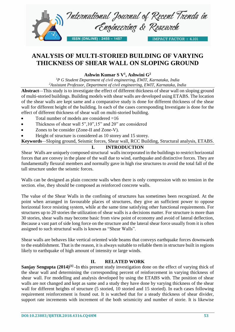
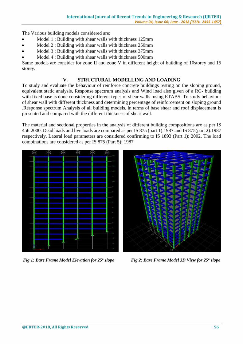
The present study is an effort towards analysis of the structure located on a sloping ground during the
earthquake. An ordinary moment resisting building of G+9 and G+14 stories located over a medium
soil is considered. The number of bays will be kept as 5 along both direction and the bay size will be
kept as 5m with the storey height being 3.5m. Slope of the ground will be kept at 25o. The building
will be analysed considering zone II and V by response spectra method using ETABS 2015 software.
Three dimensional space frame analysis will be carried out for four different building configurations
resting on sloping ground under the action of seismic load. The configurations include the thickness
of shear wall like 5”, 10”, 15”, and 20” on two different height building of 10 and 15 storeys. The main
frame remains same having constant height, constant area and constant exposures in all sides and
materials with same properties are considered for all configurations.
International Journal of Recent Trends in Engineering & Research (IJRTER) Volume 04, Issue 06; June - 2018 [ISSN: 2455-1457]
@IJRTER-2018, All Rights Reserved 56
The Various building models considered are:
Model 1 : Building with shear walls with thickness 125mm
Model 2 : Building with shear walls with thickness 250mm
Model 3 : Building with shear walls with thickness 375mm
Model 4 : Building with shear walls with thickness 500mm
Same models are consider for zone II and zone V in different height of building of 10storey and 15
storey.
V. STRUCTURAL MODELLING AND LOADING
To study and evaluate the behaviour of reinforce concrete buildings resting on the sloping ground,
equivalent static analysis, Response spectrum analysis and Wind load also given of a RC- building
with fixed base is done considering different types of shear walls using ETABS. To study behaviour
of shear wall with different thickness and determining percentage of reinforcement on sloping ground
.Response spectrum Analysis of all building models, in terms of base shear and roof displacement is
presented and compared with the different thickness of shear wall.
The material and sectional properties in the analysis of different building compositions are as per IS
456:2000. Dead loads and live loads are compared as per IS 875 (part 1):1987 and IS 875(part 2):1987
respectively. Lateral load parameters are considered confirming to IS 1893 (Part 1): 2002. The load
combinations are considered as per IS 875 (Part 5): 1987
Fig 1: Bare Frame Model Elevation for 25o slope Fig 2: Bare Frame Model 3D View for 25o slope

International Journal of Recent Trends in Engineering & Research (IJRTER) Volume 04, Issue 06; June - 2018 [ISSN: 2455-1457]
@IJRTER-2018, All Rights Reserved 57
Fig 3: Shear Wall - plan View Fig 4: Shear Wall for 25o slope - Elevation View
Fig 5: Shear Wall for 25o slope - 3D View
VI. RESULTS AND DISCUSSIONS
In this presence study the behaviour of each model is captured and results are tabulated in form of
percentage of reinforcement in shear wall, lateral displacement, storey drift, base shear, storey shear,
and time period response spectrum analysis. the performance of all the models are observed and
compare with the suitable model.

International Journal of Recent Trends in Engineering & Research (IJRTER) Volume 04, Issue 06; June - 2018 [ISSN: 2455-1457]
@IJRTER-2018, All Rights Reserved 58
6.1 Storey Displacement:
Maximum Lateral Storey Displacement in Storey 10 and Zone II
Maximum Lateral Storey Displacement in Storey 15 and Zone II
Maximum Lateral Storey Displacement in Storey 10 and Zone V
-4
-2
0
2
4
6
8
10
12
0 5 10 15 20
Sto
rey L
evel
LateralStorey Displacement in mm
Y-Direction Zone II 10 Storied Building
5 Inch
10 Inch
15 Inch
20 Inch
-5
0
5
10
15
20
0 10 20 30
Sto
rey L
evel
LateralStorey Displacement in mm
Y-Direction Zone II 15 Storied Building
5 Inch
10 Inch
15 Inch
20 Inch
-4
-2
0
2
4
6
8
10
12
0 20 40 60
Sto
rey L
evel
Lateral Storey Displacement in mm
Y-Direction Zone V 10 Storied Building
5 Inch
10 Inch
15 Inch
20 Inch
-4
-2
0
2
4
6
8
10
12
0 5 10 15 20
Sto
rey L
evel
LateralStorey Displacement in mm
X-Direction Zone II 10 Storied Building
5 Inch
10 Inch
15 Inch
20 Inch
-5
0
5
10
15
20
0 10 20 30
Sto
rey L
evel
LateralStorey Displacement in mm
X-Direction Zone II 15 Storied Building
5 Inch
10 Inch
15 Inch
20 Inch
-4
-2
0
2
4
6
8
10
12
0 20 40 60 80
Sto
rey L
evel
LateralStorey Displacement in mm
X-Direction Zone V 10 Storied Building
5 Inch
10 Inch
15 Inch
20 Inch

International Journal of Recent Trends in Engineering & Research (IJRTER) Volume 04, Issue 06; June - 2018 [ISSN: 2455-1457]
@IJRTER-2018, All Rights Reserved 59
Maximum Lateral Storey Displacement in Storey 15 and Zone V
Observation and Discussion on Lateral Displacement
By studying table 5.1 to table 5.8 and comparing their values it is observed that displacement values
are higher in zone v when compare to zone ii, however thickness of shear wall is increases the
displacement goes on decreases. The displacement Values in the structure is goes on increases from
lower storey to the higher storey in the structure.
It is observed that the displacement value in X-Direction is more when compare to Y-Direction. This
is majorly due to effect of sloping ground on the structure.
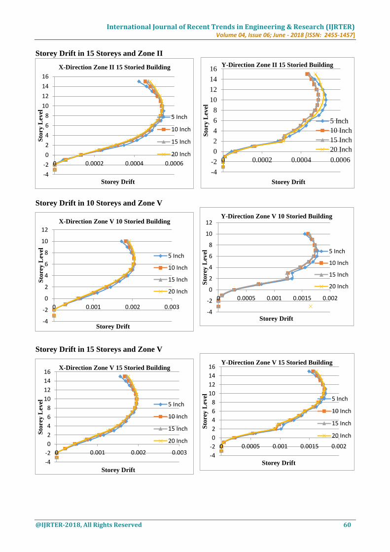
6.2 Storey Drift:
The maximum permissible Drift for an RC structure as IS 1893 – 2002 is 0.004 times of the storey
height. The maximum storey drift values for all building models in X and Y direction mentioned below.
Storey Drift in 10 Storeys and Zone II
-5
0
5
10
15
20
0 20 40 60 80
Sto
rey L
evel
LateralStorey Displacement in mm
Y-Direction Zone V 15 Storied Building
5 Inch
10 Inch
15 Inch
20 Inch
-4
-2
0
2
4
6
8
10
12
0 0.0002 0.0004 0.0006
Sto
ry L
evel
Storey Drift
Y-Direction Zone II 10 Storied Building
5 Inch
10 Inch
15 Inch
20 Inch
-4
-2
0
2
4
6
8
10
12
14
16
0 50 100
Sto
rey L
evel
LateralStorey Displacement in mm
X-Direction Zone V 15 Storied Building
5 Inch
10 Inch
15 Inch
20 Inch
-4
-2
0
2
4
6
8
10
12
0 0.0002 0.0004 0.0006 0.0008
Sto
ry L
evel
Storey Drift
X-Direction Zone II 10 Storied Building
5 Inch
10 Inch
15 Inch
20 Inch
International Journal of Recent Trends in Engineering & Research (IJRTER) Volume 04, Issue 06; June - 2018 [ISSN: 2455-1457]
@IJRTER-2018, All Rights Reserved 60
Storey Drift in 15 Storeys and Zone II
Storey Drift in 10 Storeys and Zone V
Storey Drift in 15 Storeys and Zone V
-4
-2
0
2
4
6
8
10
12
14
16
0 0.0002 0.0004 0.0006
Sto
ry L
evel
Storey Drift
Y-Direction Zone II 15 Storied Building
5 Inch
10 Inch
15 Inch
20 Inch
-4
-2
0
2
4
6
8
10
12
0 0.0005 0.001 0.0015 0.002
Sto
rey L
evel
Storey Drift
Y-Direction Zone V 10 Storied Building
5 Inch
10 Inch
15 Inch
20 Inch
-4
-2
0
2
4
6
8
10
12
14
16
0 0.0005 0.001 0.0015 0.002
Sto
rey L
evel
Storey Drift
Y-Direction Zone V 15 Storied Building
5 Inch
10 Inch
15 Inch
20 Inch
-4
-2
0
2
4
6
8
10
12
14
16
0 0.0002 0.0004 0.0006
Sto
ry L
evel
Storey Drift
X-Direction Zone II 15 Storied Building
5 Inch
10 Inch
15 Inch
20 Inch
-4
-2
0
2
4
6
8
10
12
0 0.001 0.002 0.003
Sto
rey L
evel
Storey Drift
X-Direction Zone V 10 Storied Building
5 Inch
10 Inch
15 Inch
20 Inch
-4
-2
0
2
4
6
8
10
12
14
16
0 0.001 0.002 0.003
Sto
rey L
evel
Storey Drift
X-Direction Zone V 15 Storied Building
5 Inch
10 Inch
15 Inch
20 Inch
International Journal of Recent Trends in Engineering & Research (IJRTER) Volume 04, Issue 06; June - 2018 [ISSN: 2455-1457]
@IJRTER-2018, All Rights Reserved 61
Observation and Discussion on Storey Drift
By studying it can be observed that drift values are more are less similar in Zone II and Zone V. In 10
storeys building drift values are goes on increases from base up to storeys 6 and reduces goes on to
higher stories. In 15 storied building storeys drift is gradually increases from base to storey 9 and
decreases higher storeys.
Then it observed that however thickness of shear wall increases slightly increases in storey drift also
and in storey drift values in X direction is lesser when compare to Y direction due to effect of sloping
along the Y direction.
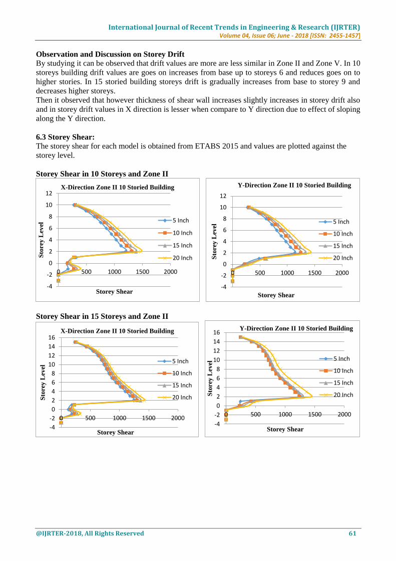
6.3 Storey Shear: The storey shear for each model is obtained from ETABS 2015 and values are plotted against the
storey level.
Storey Shear in 10 Storeys and Zone II
Storey Shear in 15 Storeys and Zone II
-4
-2
0
2
4
6
8
10
12
0 500 1000 1500 2000
Sto
rey L
evel
Storey Shear
Y-Direction Zone II 10 Storied Building
5 Inch
10 Inch
15 Inch
20 Inch
-4
-2
0
2
4
6
8
10
12
14
16
0 500 1000 1500 2000
Sto
rey L
evel
Storey Shear
Y-Direction Zone II 10 Storied Building
5 Inch
10 Inch
15 Inch
20 Inch
-4
-2
0
2
4
6
8
10
12
0 500 1000 1500 2000
Sto
rey L
evel
Storey Shear
X-Direction Zone II 10 Storied Building
5 Inch
10 Inch
15 Inch
20 Inch
-4
-2
0
2
4
6
8
10
12
14
16
0 500 1000 1500 2000
Sto
rey L
evel
Storey Shear
X-Direction Zone II 10 Storied Building
5 Inch
10 Inch
15 Inch
20 Inch

International Journal of Recent Trends in Engineering & Research (IJRTER) Volume 04, Issue 06; June - 2018 [ISSN: 2455-1457]
@IJRTER-2018, All Rights Reserved 62
Storey Shear in 10 Storeys and Zone V
Storey Shear in 15 Storeys and Zone V
Observation and Discussion on Storey Shear By Studying we can conclude that storey shear is highest at the base of the structure or where structure
meets the ground. This is because of bottom storey is level that is directly contact with the ground and
feels the maximum effect of lateral forces.
6.4 Base Shear: The base shear all values are obtained from ETABS 2015 and listed below
-4
-2
0
2
4
6
8
10
12
0 2000 4000 6000
Sto
rey L
evel
Storey Shear
Y-Direction Zone V 10 Storied Building
5 Inch
10 Inch
15 Inch
20 Inch
-2
0
2
4
6
8
10
12
14
16
0 2000 4000 6000
Sto
rey L
evel
Storey Shear
Y-Direction Zone V 15 Storied Building
5 Inch
10 Inch
15 Inch
20 Inch
-4
-2
0
2
4
6
8
10
12
0 2000 4000 6000
Sto
rey L
evel
Storey Shear
X-Direction Zone V 10 Storied Building
5 Inch
10 Inch
15 Inch
20 Inch
-2
0
2
4
6
8
10
12
14
16
0 2000 4000 6000
Sto
rey L
evel
Storey Shear
X-Direction Zone V 15 Storied Building
5 Inch
10 Inch
15 Inch
20 Inch

International Journal of Recent Trends in Engineering & Research (IJRTER) Volume 04, Issue 06; June - 2018 [ISSN: 2455-1457]
@IJRTER-2018, All Rights Reserved 63
Base Shear 10 Storeys and Zone II
Base Shear 10 Storeys and Zone V
0
200
400
600
800
1000
1200
1400
1600
1S
hea
r F
orc
e in
KN
Modal Type
Base Shear in 10 Storeys along Y Direction in Zone II
5 Inch
10 Inch
15 Inch
20 Inch
0
1000
2000
3000
4000
5000
6000
Sh
ear
Forc
e in
KN
Modal Type
Base Shear in 10 Storeys along Y Direction in Zone V
5 Inch
10 Inch
15 Inch
20 Inch
1200
1250
1300
1350
1400
1450
1500
1550
Sh
ear
Forc
e in
KN
Modal Type
Base Shear in 10 Storeys along X Direction in Zone II
5 Inch
10 Inch
15 Inch
20 Inch
0
1000
2000
3000
4000
5000
6000
7000
Sh
ear
Forc
e in
KN
Modal Type
Base Shear in 10 Storeys along X Direction in Zone V
5 Inch
10 Inch
15 Inch
20 Inch

International Journal of Recent Trends in Engineering & Research (IJRTER) Volume 04, Issue 06; June - 2018 [ISSN: 2455-1457]
@IJRTER-2018, All Rights Reserved 64
Base Shear 15 Storeys and Zone II
Base Shear 15 Storeys and Zone V
Observation and Discussion on Base Shear By studying it can be observed that however the thickness of shear wall increases the base shear values
also goes on increases. For change in thickness of shear wall the values increased about 6%.
6.5 Modal Time Period:
Time period required for each mode shape is obtained from ETABS and graph is plotted for Mode
Shape vs. Time Period.
1150
1200
1250
1300
1350
1400
1450
1500
1550
Sh
ear
Forc
e in
KN
Modal Type
Base Shear in 15 Storeys along Y Direction in Zone II
5 Inch
10 Inch
15 Inch
20 Inch
4200
4400
4600
4800
5000
5200
5400
5600S
hea
r F
orc
e in
KN
Modal Type
Base Shear in 15 Storeys along Y Direction in Zone V
5 Inch
10 Inch
15 Inch
20 Inch
1200
1250
1300
1350
1400
1450
1500
1550
1
Sh
ear
Forc
e in
KN
Modal Type
Base Shear in 15 Storeys along X Direction in Zone II
5 Inch
10 Inch
15 Inch
20 Inch
4400
4600
4800
5000
5200
5400
5600
5800
Sh
ear
Forc
e in
KN
Modal Type
Base Shear in 15 Storeys along X Direction in Zone V
5 Inch
10 Inch
15 Inch
20 Inch

International Journal of Recent Trends in Engineering & Research (IJRTER) Volume 04, Issue 06; June - 2018 [ISSN: 2455-1457]
@IJRTER-2018, All Rights Reserved 65
Observation and Discussion on Modal Time Period By studying it observed that modal time period is more 5 inch shear wall compare to other shear wall.
The thickness of shear wall increases time period goes on decrease.
VII. CONCLUSIONS
1. From the result it is concluded that when the seismic zone changes from Zone-II to Zone-V the
percentage of Reinforcement increases.
2. It is concluded that for better earthquake resisting design the thickness of shear wall is not useful.
3. Frommoverall observation it issfound that shear wall thickness of 10 inch for 10 storey and 15
storey levels provide proper seismic safeties with minimum amount of the reinforcement (in case
of Zone II to Zone V). The thickness of 20 inch shear wall provides proper seismic safety.
4. It cannbe conclude that 10 inch shear wall thickness will be the sufficient in the case of the low
rises to medium rises buildings, which will provided the lot of cost benefits.
5. In case off Zone V only 10 inch thick wall is founded to be most safe and economic thickness.
6. As the thickness of shear wall increases the displacement goes on decreases.
7. It can conclude that increasing shear wall thickness the time period goes on decreases.
8. It can conclude that increasing the thickness of shear wall the base shear is also increases.
0
0.2
0.4
0.6
0.8
1
1.2
1.4
1.6
1.8
1 2 3 4 5 6 7 8 9 10 11 12
Tim
e P
erio
d (
Sec
)
Modes
Time period for zone-II (sec) Storey 15
5 inch
10 inch
15 inch
20 inch
0
0.2
0.4
0.6
0.8
1
1.2
1.4
1.6
1.8
1 2 3 4 5 6 7 8 9 10 11 12
Tim
e P
erio
d (
Sec
)
Modes
Time period for zone-V (sec) Storey 15
5 inch
10 inch
15 inch
20 inch
0
0.2
0.4
0.6
0.8
1
1.2
1 2 3 4 5 6 7 8 9 10 11 12
Tim
e P
erio
d (
Sec
)
Modes
Time period for zone-II (sec) Storey 10
5 inch
10 inch
15 inch
20 inch
0
0.2
0.4
0.6
0.8
1
1.2
1 2 3 4 5 6 7 8 9 10 11 12
Tim
e P
erio
d (
Sec
)
Modes
Time period for zone-V (sec) Storey 10
5 inch
10 inch
15 inch
20 inch

International Journal of Recent Trends in Engineering & Research (IJRTER) Volume 04, Issue 06; June - 2018 [ISSN: 2455-1457]
@IJRTER-2018, All Rights Reserved 66
REFERENCES I. Likhitharadhya Y R, Praveen J V, Sanjith J and Ranjith “A Seismic Analysis of Multi-Storey Building Resting
on Flat Ground and Sloping Ground”, IJIRSET, Vol. 5, Issue 6, June 2016.
II. Md. Samdani Azad, Syed Hazni and Gani “Comparative Study of Seismic Analysis of Multi-storey Buildings
with Shear Walls and Bracing Systems”, IJASGE, Vol. 05, No. 03, July 2016
III. Manjunath C S and Siddu Karthik C S “Seismic Performance of R C Buildings on Sloping Grounds with Different
Types of Bracing Systems”, IJERT, Vol. 5, Issue 02, Feb. 2016
IV. Paresh G Mistry and Hemal J Shah “Seismic Analysis of Building on Sloping Ground Considering Bi-Directional
Earthquake”, IJSDR, Volume 1, Issue 4 April 2016
V. Sripriya Arjun and Arathi S A “Study on Dynamic Characteristics of RC Buildings on Hill Slopes”, IJSR, Volume
5, Issue 7, July 2016
VI. S K Hirde and N K Shelar “Effect of Positioning of RC Shear Walls on Seismic Performance of Buildings Resting
on Plain and Sloping Ground”, IJCET, Vol.5, No.3 June 2015
VII. Mohd. Atif, Prof. Laxmikant Vairagade and Vikrant Nair “Comparative Study on Seismic Analysis of Multi-
Storey Building Stiffened with Bracing and Shear Wall”, IRJET, Vol. 2, Issue 05, Aug. 2015
VIII. Nagarjuna and Shivakumar B Patil “Lateral Stability of Multi-storey Building on Sloping Ground”, IRJET, Vol.
2, Issue 04, July 2015