Analysis of Misalignment Journal Bearings Considering the ...
5
Analysis of Misalignment Journal Bearings Considering the Turbulent Effects MENG Fanwei 1, a * , LIU Rui 1,b ,QU Po 1,c and XU Guohui 2,d 1 Institute of Lanzhou Petrochemical Company, Lanzhou China730060 2 State Key Laboratory for Strength and Vibration of Mechanical Structures (Xi’an Jiaotong University) , Xi’an China 710049 a [email protected], b [email protected], c [email protected], d [email protected] Keywords: wear damage; turbulence effect; misalignment; oil pressure Abstract. In order to investigate the cause of the typical bush rupture and wear damages in the journal bearing of the steam turbine generator set. The misalignment bearing analysis model of considering lubrication turbulence effects was established. The pressure, thickness distribution of the oil film is obtained. Compared with the alignment results, analysis results can be well explains the bearing bush burst at bearings maximum pressure place due to bearing misalignment, resulting in the film maximum pressure is off-center position, and larger than normal result. The bearing bush burst make friction being intensified, the oil temperature increasing, the viscosity drop, eccentricity bigger, attitude angle smaller, bearing point down, the minimum film thickness smaller, thus causing the wear damages,until shutdown. It explains the bearing failure phenomena studied in this paper that bush occurred half wear and bearing rupture location downstream of the minimum film thickness position. Introduction Due to improper installation of the shafting or excessive rotor imbalance, the rotor will skew and cause bearing failure [1]. With the bearings supporting getting growing attention in recent years, studies of bearing failure analysis gains popularity among people. Iwasawa and co-authors [2] study the effect that surface roughness and mechanical properties have on the rotor and pad Collision - abrasion extent. Ushijima, Okamoto and co-authors [3-5] established a similar wear bearing model as Orchard’s [6], considering the impact of the contact reaction force on the contact surfaces. Wang and co-authors [7] considered the effect of the lubricating oil performance on rupture and wear of the pad. In domestic, Deng et al [8] study the TEHD analysis of the bearings, taking into account the shaft deformation caused by surface topography, thermal effects and the bearing surface deformation, which leads to shaft tilting in bearings. Based on former failure forms, the rupture of bearing usually happen where the film thickness is minimum, also the maximum pressure of the oil film. While the rupture location is obviously appeared in the downstream and the location is closer to the edge rather than the middle of the bush shown in Fig. 1. Fig.1 Failure bearing pictures To clarify the reasons, based on previous research, this article studies and discusses reasons of such failure with turbulence effects into account. 5th International Conference on Civil Engineering and Transportation (ICCET 2015) © 2015. The authors - Published by Atlantis Press 18
Transcript of Analysis of Misalignment Journal Bearings Considering the ...

Analysis of Misalignment Journal Bearings Considering the
Turbulent Effects
MENG Fanwei1, a *
, LIU Rui1,b
,QU Po1,c
and XU Guohui2,d
1Institute of Lanzhou Petrochemical Company, Lanzhou China730060
2 State Key Laboratory for Strength and Vibration of Mechanical Structures(Xi’an Jiaotong University),
Xi’an China 710049
[email protected], [email protected], [email protected], [email protected]
Keywords: wear damage; turbulence effect; misalignment; oil pressure
Abstract. In order to investigate the cause of the typical bush rupture and wear damages in the journal
bearing of the steam turbine generator set. The misalignment bearing analysis model of considering lubrication
turbulence effects was established. The pressure, thickness distribution of the oil film is obtained. Compared
with the alignment results, analysis results can be well explains the bearing bush burst at bearings maximum
pressure place due to bearing misalignment, resulting in the film maximum pressure is off-center position, and
larger than normal result. The bearing bush burst make friction being intensified, the oil temperature increasing,
the viscosity drop, eccentricity bigger, attitude angle smaller, bearing point down, the minimum film thickness
smaller, thus causing the wear damages,until shutdown. It explains the bearing failure phenomena studied in
this paper that bush occurred half wear and bearing rupture location downstream of the minimum film
thickness position.
Introduction
Due to improper installation of the shafting or excessive rotor imbalance, the rotor will skew and cause
bearing failure [1]. With the bearings supporting getting growing attention in recent years, studies of bearing
failure analysis gains popularity among people. Iwasawa and co-authors [2] study the effect that surface
roughness and mechanical properties have on the rotor and pad Collision - abrasion extent. Ushijima,
Okamoto and co-authors [3-5] established a similar wear bearing model as Orchard’s [6], considering the
impact of the contact reaction force on the contact surfaces. Wang and co-authors [7] considered the effect
of the lubricating oil performance on rupture and wear of the pad. In domestic, Deng et al [8] study the TEHD
analysis of the bearings, taking into account the shaft deformation caused by surface topography, thermal
effects and the bearing surface deformation, which leads to shaft tilting in bearings. Based on former failure
forms, the rupture of bearing usually happen where the film thickness is minimum, also the maximum pressure
of the oil film. While the rupture location is obviously appeared in the downstream and the location is closer to
the edge rather than the middle of the bush shown in Fig. 1.
Fig.1 Failure bearing pictures
To clarify the reasons, based on previous research, this article studies and discusses reasons of such failure
with turbulence effects into account.
5th International Conference on Civil Engineering and Transportation (ICCET 2015)
© 2015. The authors - Published by Atlantis Press 18

Misalignment bearing model.
According to the relevant test data and pictures of the bearing fault, this paper establishes misalignment
bearing theory model for different bearing fault type, shown in Fig. 2.
Fig 2. System of misaligned journal bearing
xOy is the bearing coordinates. O is the origin of the coordinate system. c is the journal center. e0 is the
center bearing eccentricity. θ is the deviation angle. α is the angle from θ to the center of front face. D is the
bearing width. e’ is the central distance between both ends of the surfaces.
Typically, the lubricant film is deemed as incompressible fluid. Ignoring oil weight and inertia force, the
bearing pressure distribution in turbulent conditions can be expressed by Reynolds equation[9] as follows: 3 3 ( )
2x z
h p h p U h
x k x z k z x
(1)
Where
'
01cos( ) ( ) cos( )
2
zh c e e
D
ρ is the lubricant density; μ is the dynamic viscosity lubricant; p is the film pressure; h is the film thickness;
c is the bearing clearance; U is the relative velocity between two solid surfaces in x direction.
kx, kz are the turbulence factors, which are partial functions of the Reynolds number. By the wall's law
[10], they can be obtained as follows: 0.901
0.982
12 0.0136(Re)
12 0.0043(Re)
x
z
k
k
(2)
The Reynolds number in (2) can be calculated as follows:
e
UhR
(3)
Warm-velocity Equation.
Under normal circumstances, the oil lubricating viscosity will decrease as the temperature rises. Their
relationship can be expressed as a group of viscosity values measured at different temperatures or the
resulting curve, which may also be expressed approximately by empirical formula. In this paper, we use
common Reynolds warm sticky relationship [11]:
( )inT T
ine
(4)
Where:Tin is the inlet temperature; μin is the viscosity at the temperature of Tin; Ⅹ is the warm-sticky index.
Boundary condition of the oil film pressure.
For cylindrical bearings, there are different assumptions on pressure conditions. In this paper, Reynolds
boundary conditions were used in the calculation [12].
0 0p
p p
, (5)
Result and analysis.
The following table is the main parameters of bearing and lubricating oil.
19

Table 1: Parameters of bearing and lubricating oil
Parameters Value
Journal radius r/ mm 84.5
Bearing radius R/ mm 85
Bearing width L/mm 60
Oil inlet temp Tin/°C 40
Oil viscosity μ in/ Pa.s 0.02207
Oil density ρ / kg/3m 850
Load capacity W/ kN 17.5
Film pressure and thickness.
When calculated according to the theory of laminar flow, turbulence factor takes constant value 12; when
calculated according to the theory of turbulence, turbulence factor changes with the Reynolds number.
According to the Eq.3, under different speed, Reynolds number changes with the bearing angle as shown in
Fig. 3. There can be seen that the film has appeared turbulent flow regime at the rated speed 3000r / min.
Fig. 3 The Reynolds number distribution
According to the results of the turbulence theory, failing bearing’s corresponding quiescent point is
approximately at ε = 0.61, θ = 52.8 °, which is at its carrying capacity W = 17668N. Its pressure distribution
is shown in Fig.4. At rated speed, the pressure distribution curve’s maximum pressure is Pmax = 4.76MPa, at
φ = 293º, which is close to the field testing. Film thickness is shown in Fig.5, whose corresponding minimum
film thickness is at φ = 313.8 °.
Fig. 4 The pressure distribution of turbulence theory Fig. 5 The film thickness distribution
According to the misalignment bearing model, when the distance between both ends of the surface is
0.5mm, its pressure distribution can be shown as Fig. 6, the maximum pressure under rated speed is Pmax =
20
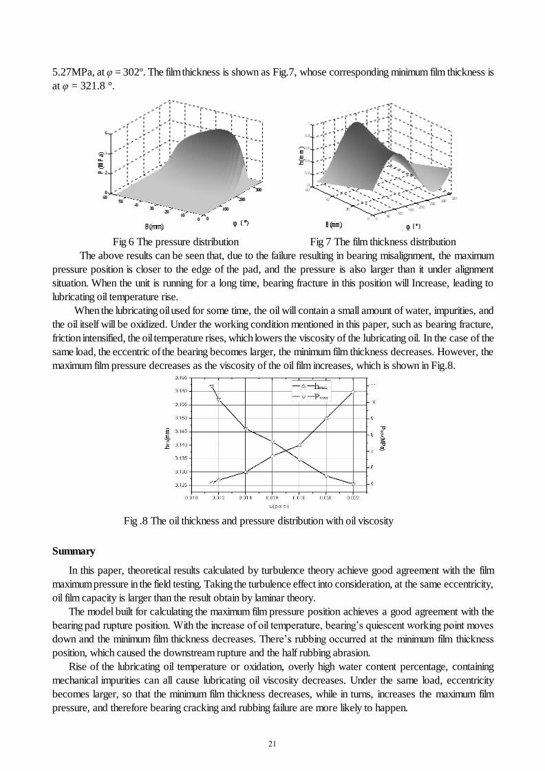
5.27MPa, at φ = 302º. The film thickness is shown as Fig.7, whose corresponding minimum film thickness is
at φ = 321.8 °.
Fig 6 The pressure distribution Fig 7 The film thickness distribution
The above results can be seen that, due to the failure resulting in bearing misalignment, the maximum
pressure position is closer to the edge of the pad, and the pressure is also larger than it under alignment
situation. When the unit is running for a long time, bearing fracture in this position will Increase, leading to
lubricating oil temperature rise.
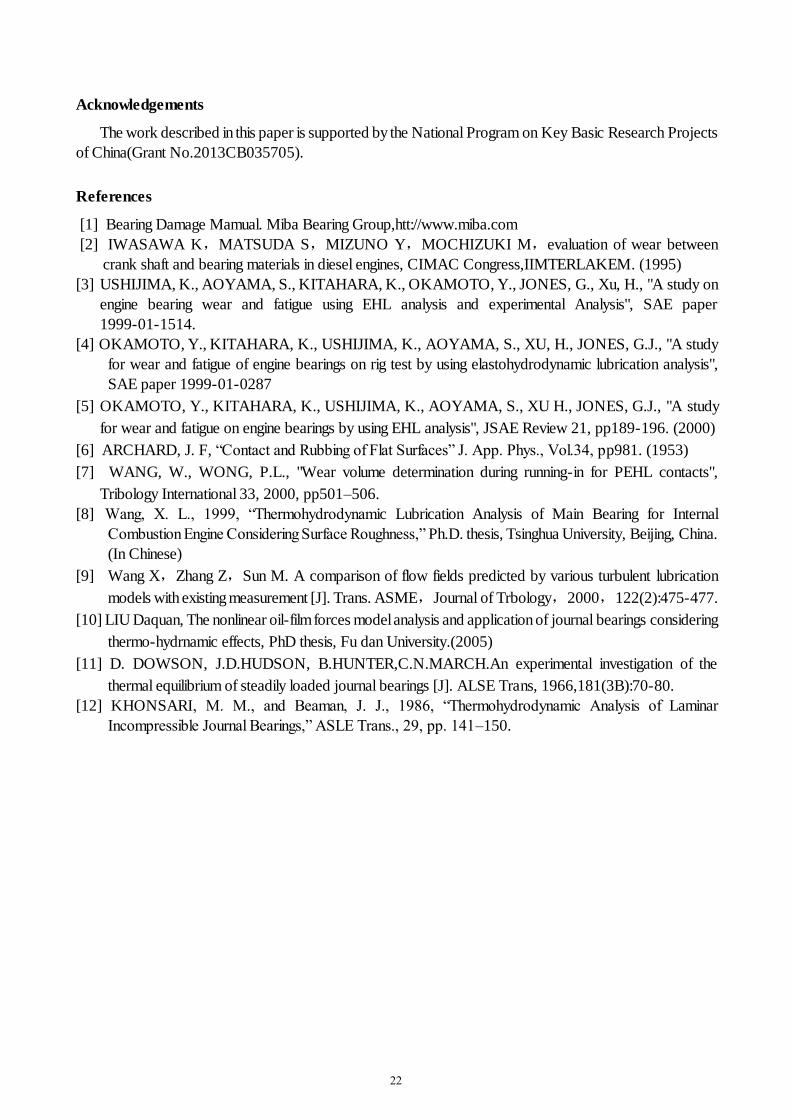
When the lubricating oil used for some time, the oil will contain a small amount of water, impurities, and
the oil itself will be oxidized. Under the working condition mentioned in this paper, such as bearing fracture,
friction intensified, the oil temperature rises, which lowers the viscosity of the lubricating oil. In the case of the
same load, the eccentric of the bearing becomes larger, the minimum film thickness decreases. However, the
maximum film pressure decreases as the viscosity of the oil film increases, which is shown in Fig.8.
Fig .8 The oil thickness and pressure distribution with oil viscosity
Summary
In this paper, theoretical results calculated by turbulence theory achieve good agreement with the film
maximum pressure in the field testing. Taking the turbulence effect into consideration, at the same eccentricity,
oil film capacity is larger than the result obtain by laminar theory.
The model built for calculating the maximum film pressure position achieves a good agreement with the
bearing pad rupture position. With the increase of oil temperature, bearing’s quiescent working point moves
down and the minimum film thickness decreases. There’s rubbing occurred at the minimum film thickness
position, which caused the downstream rupture and the half rubbing abrasion.
Rise of the lubricating oil temperature or oxidation, overly high water content percentage, containing
mechanical impurities can all cause lubricating oil viscosity decreases. Under the same load, eccentricity
becomes larger, so that the minimum film thickness decreases, while in turns, increases the maximum film
pressure, and therefore bearing cracking and rubbing failure are more likely to happen.
21
Acknowledgements
The work described in this paper is supported by the National Program on Key Basic Research Projects
of China(Grant No.2013CB035705).
References
[1] Bearing Damage Mamual. Miba Bearing Group,htt://www.miba.com
[2] IWASAWA K,MATSUDA S,MIZUNO Y,MOCHIZUKI M,evaluation of wear between
crank shaft and bearing materials in diesel engines, CIMAC Congress,IIMTERLAKEM. (1995)
[3] USHIJIMA, K., AOYAMA, S., KITAHARA, K., OKAMOTO, Y., JONES, G., Xu, H., "A study on
engine bearing wear and fatigue using EHL analysis and experimental Analysis", SAE paper
1999-01-1514.
[4] OKAMOTO, Y., KITAHARA, K., USHIJIMA, K., AOYAMA, S., XU, H., JONES, G.J., "A study
for wear and fatigue of engine bearings on rig test by using elastohydrodynamic lubrication analysis",
SAE paper 1999-01-0287
[5] OKAMOTO, Y., KITAHARA, K., USHIJIMA, K., AOYAMA, S., XU H., JONES, G.J., "A study
for wear and fatigue on engine bearings by using EHL analysis", JSAE Review 21, pp189-196. (2000)
[6] ARCHARD, J. F, “Contact and Rubbing of Flat Surfaces” J. App. Phys., Vol.34, pp981. (1953)
[7] WANG, W., WONG, P.L., "Wear volume determination during running-in for PEHL contacts",
Tribology International 33, 2000, pp501–506.
[8] Wang, X. L., 1999, “Thermohydrodynamic Lubrication Analysis of Main Bearing for Internal
Combustion Engine Considering Surface Roughness,” Ph.D. thesis, Tsinghua University, Beijing, China.
(In Chinese)
[9] Wang X,Zhang Z,Sun M. A comparison of flow fields predicted by various turbulent lubrication
models with existing measurement [J]. Trans. ASME,Journal of Trbology,2000,122(2):475-477.
[10] LIU Daquan, The nonlinear oil-film forces model analysis and application of journal bearings considering
thermo-hydrnamic effects, PhD thesis, Fu dan University.(2005)
[11] D. DOWSON, J.D.HUDSON, B.HUNTER,C.N.MARCH.An experimental investigation of the
thermal equilibrium of steadily loaded journal bearings [J]. ALSE Trans, 1966,181(3B):70-80.
[12] KHONSARI, M. M., and Beaman, J. J., 1986, “Thermohydrodynamic Analysis of Laminar
Incompressible Journal Bearings,” ASLE Trans., 29, pp. 141–150.
22