
Analysis of Magnetic Flux Linkage Distribution in Salient...
13
260 Iranian Journal of Electrical & Electronic Engineering, Vol. 7, No. 4, Dec. 2011 Analysis of Magnetic Flux Linkage Distribution in Salient- Pole Synchronous Generator with Different Kinds of Inter- Turn Winding Faults H. Yaghobi*, K. Ansari** and H. Rajabi Mashhadi** Abstract: A reliable and accurate diagnosis of inter-turn short circuit faults is a challenging issue in the area of fault diagnosis of electrical machines. The purpose of this study is to present a more efficient technique in fault detection and to provide a reliable method with low-cost sensors and simple numerical algorithms which not only detects the occurrence of the fault, but also locates its position in the winding. Hence, this paper presents a novel method for diagnosis of different kinds of inter-turn winding faults in a salient-pole synchronous generator based on changes in the magnetic flux linkage. It describes the influence of inter-turn winding faults on the magnetic flux distribution of the generator. The main feature of the proposed method is its capability to identify the faulty coils under two types of inter-turn winding faults. Also, the occurrence of two other types of faults can be detected by the proposed technique. Simple algorithm, low cost sensor and sensitivity are the other features of the proposed technique. Experimental results derived from a 4- pole, 380V, 1500 rpm, 50 Hz, 50 KVA, 3-phase salient-pole synchronous generator confirm the validity of the proposed method. Keywords: Synchronous Generator, Fault Diagnosis, Linkage Flux Analysis, Inter-turn Winding Fault. 1 Introduction1 The stator’s internal short circuit current in the synchronous generator may be several times larger than its terminal short circuit current [1]. When an inter-turn short circuit occurs, the shorted turn will act as the secondary winding of an autotransformer. Consequently, a very large circulating current will flow in the faulted turn. This circulating current creates excessive heat and high magnetic forces in the machine [2].Therefore, it is very important to have a careful analysis of the internal faults in synchronous generators to increase their useful life and reliability. Hence a reliable and accurate diagnosis of inter-turn short circuit faults is a challenging problem in the area of fault diagnosis of electrical machines. The expertise in this field is still in permanent evolution and new methods appear every year [3]. The purpose of this study is to be more efficient in fault detection and to provide a reliable Iranian Journal of Electrical & Electronic Engineering, 2011. Paper first received 14 Nov. 2010 and in revised form 25 Jun. 2011. * The Author is with the Department of Engineering, Sari Branch, Islamic Azad University, Sari, Iran. E-mail: [email protected] * The Authors are with the Department of Electrical Engineering, Ferdowsi University of Mashhad, Iran. E-mail: [email protected] method with low-cost sensors and simple numerical algorithms [3] which not only detects the occurrence of the fault, but also locates its position in the winding. However, the behavior of the synchronous machine under internal faults has not been thoroughly studied [4], and few methods exist for analyzing internal faults in synchronous machines [1], [4], [5], [8]-[14]. Most of these methods are based on the mathematical, two reaction theory and winding function approach. Two reaction theory is derived from the assumption that the machine windings are symmetrical. When an internal fault occurs on the stator winding of a synchronous machine, it divides the faulty winding into a number of sections and the symmetry between these faulted sections and the rest of the machine windings will lose. Therefore, the models based on the two-reaction theory cannot be useful to analyze internal faults [5]. Usually, mathematical methods do not consider the saturation effects or consider the saturation effects in synchronous machines with the dqo analysis which uses the superposition principle to solve for the d-axis path and the q-axis path separately. However, superposition is not valid in modeling saturation effects due to the nonlinearity of the saturation phenomena [6], [7]. In a salient pole synchronous machine, the air gap is
Transcript of Analysis of Magnetic Flux Linkage Distribution in Salient...

260 Iranian Journal of Electrical & Electronic Engineering, Vol. 7, No. 4, Dec. 2011
Analysis of Magnetic Flux Linkage Distribution in Salient-Pole Synchronous Generator with Different Kinds of Inter-Turn Winding Faults H. Yaghobi*, K. Ansari** and H. Rajabi Mashhadi**
Abstract: A reliable and accurate diagnosis of inter-turn short circuit faults is a challenging issue in the area of fault diagnosis of electrical machines. The purpose of this study is to present a more efficient technique in fault detection and to provide a reliable method with low-cost sensors and simple numerical algorithms which not only detects the occurrence of the fault, but also locates its position in the winding. Hence, this paper presents a novel method for diagnosis of different kinds of inter-turn winding faults in a salient-pole synchronous generator based on changes in the magnetic flux linkage. It describes the influence of inter-turn winding faults on the magnetic flux distribution of the generator. The main feature of the proposed method is its capability to identify the faulty coils under two types of inter-turn winding faults. Also, the occurrence of two other types of faults can be detected by the proposed technique. Simple algorithm, low cost sensor and sensitivity are the other features of the proposed technique. Experimental results derived from a 4-pole, 380V, 1500 rpm, 50 Hz, 50 KVA, 3-phase salient-pole synchronous generator confirm the validity of the proposed method. Keywords: Synchronous Generator, Fault Diagnosis, Linkage Flux Analysis, Inter-turn Winding Fault.
1 Introduction1 The stator’s internal short circuit current in the synchronous generator may be several times larger than its terminal short circuit current [1]. When an inter-turn short circuit occurs, the shorted turn will act as the secondary winding of an autotransformer. Consequently, a very large circulating current will flow in the faulted turn. This circulating current creates excessive heat and high magnetic forces in the machine [2].Therefore, it is very important to have a careful analysis of the internal faults in synchronous generators to increase their useful life and reliability. Hence a reliable and accurate diagnosis of inter-turn short circuit faults is a challenging problem in the area of fault diagnosis of electrical machines. The expertise in this field is still in permanent evolution and new methods appear every year [3]. The purpose of this study is to be more efficient in fault detection and to provide a reliable Iranian Journal of Electrical & Electronic Engineering, 2011. Paper first received 14 Nov. 2010 and in revised form 25 Jun. 2011. * The Author is with the Department of Engineering, Sari Branch, Islamic Azad University, Sari, Iran. E-mail: [email protected] * The Authors are with the Department of Electrical Engineering, Ferdowsi University of Mashhad, Iran. E-mail: [email protected]
method with low-cost sensors and simple numerical algorithms [3] which not only detects the occurrence of the fault, but also locates its position in the winding.
However, the behavior of the synchronous machine under internal faults has not been thoroughly studied [4], and few methods exist for analyzing internal faults in synchronous machines [1], [4], [5], [8]-[14]. Most of these methods are based on the mathematical, two reaction theory and winding function approach. Two reaction theory is derived from the assumption that the machine windings are symmetrical. When an internal fault occurs on the stator winding of a synchronous machine, it divides the faulty winding into a number of sections and the symmetry between these faulted sections and the rest of the machine windings will lose. Therefore, the models based on the two-reaction theory cannot be useful to analyze internal faults [5]. Usually, mathematical methods do not consider the saturation effects or consider the saturation effects in synchronous machines with the dqo analysis which uses the superposition principle to solve for the d-axis path and the q-axis path separately. However, superposition is not valid in modeling saturation effects due to the nonlinearity of the saturation phenomena [6], [7]. In a salient pole synchronous machine, the air gap is

Yaghobi et a
nonuniform ais a functionalong the d-aof saturation[7]. The metconsider the
Referencearth fault onthe windingmagnetic hysaturation efof simplificaMethod usedharmonic comThis leads internal fault[1], [8], [11]in [8] and [considered acomposed ofcoils. The calculation generalizatiosynchronousmany coils in
In [1], onparts, whosinvariability.where eachmaximum vwinding partfault problemwindings arhence, the ap
On the odiagnose faumachine dow[14]. Hence, electrical ma[15].Conditiocould prevenmachine opefactors need suitable moindustrial enpresented in impossible tothe compleabnormalitie
Fault mousing magneas a topicalleakage fluxefficient techflux sensor ihas been usecircuit [18]-
l: Analysis of
and the reluctn of time. Taxis and the qn along these thods presentesaturation inse [4] has inven the synchro
g function apysteresis, sloffect are not taation [4]. In td in [10], onlymponents of tto a substants give rise to]. In the multi9], a salient-as made of sf the actual l
inaccuraciesof loop
on of this m machine, en the stator anne of the parase magnetic . Indeed, the h fundamentalue [11]. Retitioning techm in sinuso
re scarcely fopplication of thother hand,
ults at their vewntime can as a recent tre
achines has beon monitorinnt tragic losseeration. It mu
to be considonitoring metnvironment. T
[16]. It is vero gratify all texity of thes, and the natuonitoring of etic field measl subject of x detection hnique for dias located outs
ed for the dete[22]. Unfortu
f Magnetic Flu
tance of the mherefore the
q-axis are varytwo axes is
ed in [1], [5]side the machiestigated the eonous machinpproach. In totted stator aken into accothe Symmetri
y the fundamentime and spacntial amount o increased hiloop method pole synchroseveral electrloops that ares and com
inductances model to dispecially for
nd rotor [1], [4allel paths is
axis locatmagnetic ax
tal componeeferences [11nique for solidal wound
found in elechis method is it has now ery inceptioncause heavy end, monitorineen considereg of synchro
es and prepareust be noted tdered when sethod for aphe most impory difficult anthe criteria, me degradatioure of the faulrotating elec
surements havinvestigation
has been ingnosis. In thisside the machection of statounately, the e
ux Linkage Dis
magnetic flux pmagnetic flu
ying and the lealso changea
, [8]-[13] do ine. effects of turne inductancesthis method, effects and ount for the sical Componental and the the are considerof error, si
harmonic contthat is propo
nous machineric circuits, ee formed by
mplexity in prevents
iverse types machines w
4], [11]. divided into ttions have xis should locnt obtains
1]-[13] presenving the intermachines. S
ctrical machinalso limited.become vital; as unschedufinancial los
ng techniquesd very import
onous generate precise viewthat a varietyelecting the mplication in ortant factors nd, in most camainly becauseon mechanislt [16]. ctrical machive been propon [3], [17]. Tntroduced as s method leakine. This meth
or winding shefficiency of
istribution …
path uxes evel able not
n-to-s by
the the
sake ents hird red. ince tent
osed e is
each the the the of
with
two the
cate the
nt a rnal uch nes;
l to uled sses s for rtant tors
w of y of most
an are
ases, e of sms,
ines osed The
an kage hod
hort-this
methe
diain chaof idewinfauSimoththimestaacc 2
oftpercondesstasamin brapre
in grophathefrophato impan andto-simbe
shotwocur
Fig. circu
ethod has not ye signal proces
In this papeagnosis of diff
a salient-poange in the m
the proposeentifying the fnding faults. ults can be mple algorithmher features chs method, th
easured via sator wedges incessible on the
Description Early stages
ten have inrformance; honsiderable istructive failu
ator winding ame branch, tu
the same phanches in diffesented in Fig
Undetected tthe deforme
ows and is chaase faults [24]e stator windinom this fault [2ase-to-groundthe stator winportant to anaearly stage to
d involved syturn short circ
mulated. Howeextended to c
2.1 MMFigure 1 (b)
ort circuit haso points, m arrents produc
1 (a) Four kinuit between two
yet been pointssing used forer, we presenferent kinds oole synchronomagnetic flux ed method ifaulty coils unAlso, occurredetected by m, low cost haracterized the generator earch coils s
nside the mache market and i
of the Inter-Tof internal fa
nsignificant eowever such finter-turn fa
ures [23]. Fourare stator turn-urn-to-turn shohase, turn-to-ferent phases, . 1 [8]. turn-to-turn fad region of anged into ph]. This type ofng failures and24]. In additio
d fault may lending and corealyze and deteo prevent furthystems. In thiscuit in the samever, this disc
cover all kinds
MF Distortionillustrates the
s happened inand n. Also Fe opposite M
(a) nds of internal
points, m and n
nted out since r harmonic dent a novel meof inter-turn wnous generato
linkage. The is that it isnder two typesence of two o
the proposesensor and s
the proposed air gap flu
sensor installhine. This senits cost is very
Turn Winingaults in stator effects on tfaults may quaults and r kinds of inte-to-turn shortort circuit of -turn short ci
and turn-to-e
aults lead to ga winding w
hase-to-groundf faults is a mad other faults on, a severe fead to irrevere [23]. Therefect stator interher damage tos section, an me branch is dcussion and sis of internal fa
n Due to the Fe case when
n the same braFig. 1 (b) sh
MMFs, one of
faults [8]. (b)n [16].
261
it is related totection [3]. ethod for thewinding faultsor using the
main features capable ofs of inter-turnother types ofed technique.sensitivity aretechnique. In
ux linkage ised under the
nsor is readilyy low.
g Faults winding maythe machineuickly lead tosubsequently
ernal faults incircuit in the
two branchesircuit of twoearth fault are
generated heatwhich finallyd or phase-to-ajor reason ofmay be result
fault such as arsible damagefore, it is veryr-turn faults ato the machineinternal turn-discussed andimulation canaults.
Fault a turn-to-turnanch betweenows that two
f which is the
(b) ) Inter-turn sho
1
o
e s e e f n f . e n s e y
y e o y n e s o e
t y -f t a e y t e -d n
n n o e
ort

262 Iranian Journal of Electrical & Electronic Engineering, Vol. 7, No. 4, Dec. 2011
phase current and the other one is the short circuit current (The difference between these two currents is defined as circulating current cirI ). Therefore, the main effect of the inter-turn short circuits decreases the MMF close to the short-circuited turns [16]. Under ideal conditions, the machine has an air-gap magneto-motive force which varies sinusoidally in space and time. In this condition, the air-gap MMF function M is the sum of the field and the armature winding MMF:
(1) ABCf MMM +=
The field winding MMF is defined by the equation:
(2) fnfff MINM =
where fN denotes the number of field winding turns per pole and fI is the field current. The function fnMdenotes a unitary trapezoid function given by:
(3) ))tw(2pnsin(
nsin
f14M mm
,...5,3,1n2
ffn −θ
γγπ
= ∑=
mθ denotes the mechanical angular coordinate in a stator fixed reference frame. t is the time and p is the pole number. fγ is the angle between the height and lateral side of the trapezoid function fnM . Also, the three-phase armature MMF can be expressed as [25]:
(4)
)p3
4(2pnsin((M̂.i
)p3
4(2pnsin((M̂.i
)2pnsin(M̂.iM
m,...5,3,1n
nc
m,...5,3,1n
nb
m,...5,3,1n
naABC,Nph
π+θ
+π
−θ
+θ=
∑
∑
∑
=
=
=
where ai , bi , and ci denote the currents in the winding
phases A, B, and C respectively. The coefficients nM̂ are given by:
(5) )n(k)n(k)n(kn1
pN4M̂ slpd
phn π=
where phN denotes the total number of winding turns per phase circuit. Expressions for the distribution, pitch and slot opening factors (symbols )n(kd , )n(kp , and )n(ksl respectively), can be found in [26].
Now, consider a turn-to-turn short circuit in the same branch on stator winding in phase A. During fault generator operation, the MMF function can be accordingly expressed as follows:
(6) NDC,B,NphA),NDNph(f MMMMM −++= − where A),NDNph(M − denotes the armature winding MMF of the faulty phase A. In fact, when a short circuit occurs, the number of phase winding turns and the MMF produced by this winding reduce. This MMF can be expressed as follows:
(7) )n(k)n(k)n(k
n1
pNNph4M̂
, )2pnsin(M̂.iM
slpdD
n
m,...5,3,1n
naA),NDNph(
−π
=
θ= ∑=
−
DN corresponds to the winding turns being short. Also,
C,B,NphM denotes the armature winding MMF of the healthy phase B, C and can be expressed as follows:
(8) )
p34(
2pnsin((M̂.i
)p3
4(2pnsin((M̂.i M
m,...5,3,1n
nc
m,...5,3,1n
nbC,B,Nph
π+θ
+π
−θ=
∑
∑
=
=
During the fault, the coefficients nM̂ in these phases are not changed and are given by Eq. (5).
NDM denotes the MMF produced by the short-circuit current is contrary to the MMF produced by phase winding and can be expressed as follows:
(9) DDsc ,ND iNM ×= On the other hand, the amplitude of the fault current,
Di , depends on the fault resistance, DR , and the induced
voltage, scv , in the shorted coil. Hence, Di can be expressed as follows [27]:
(10) D
scD R
vi =
In addition, for frequencies lower than 10 kHz, the voltage gradient from turn to turn is constant and therefore the voltage is approximately distributed uniformly across the turns of the phase winding. Moreover, for a winding factor, approximately equal to one, the voltage in the shorted turns can be expressed as follows [27]:
(11) phph
Dsc v)
NN(v =
This induced voltage, scv , correspondingly depends on the number of shorted turns,
DN , that is associated with this short portion of the faulty phase winding in the machine.
phN is the effective number of turns of the
phase winding and phv is the phase voltage. Hence, the fault current can be stated as follows:
(12) )NN)(
Rv
(iph
D
D
phD =
Consequently, faulty operation will cause a distortion in the air-gap magneto-motive force of the machine.
2.2 Magnetic Flux Distribution
Modeling and analysis of salient-pole synchronous generator is very complicated, especially when an inter-turn winding fault occurs in a generator equipped with a stator winding consisting of parallel branches. In many

Yaghobi et al: Analysis of Magnetic Flux Linkage Distribution … 263
applications, a 2-D finite element analysis gives relatively precise prediction of the magnetic field distribution and machine performance. Some limitations of 2-D analysis imply that the use of 3-D analysis is inevitable if an accurate analysis is needed. These limitations are presented in [28]. In this research, in order to improve the overall accuracy, the magnetic field distribution is calculated by 3D-FEM using ANSYS workbench software. In modeling of the salient-pole synchronous generator, saliency and slotting, magnetic saturation effects, and the position of the winding inside the stator are included in the FEM modeling. Slotting and the position of the winding can be seen in Fig. 2(a). In order to prevent confusion, only excitation and phase A windings are shown in Fig. 2(a). Also, the effect of magnetic saturation was included in the FEM software by using B-H curves of the rotor and stator cores. When an internal fault is on the stator winding, the fault winding is divided into some sub coils. In order to model this using FEM, the ampere-turns distribution for the windings should be represented in the model. It is necessary to consider the short circuited turns separately in the FEM model when confronting with the DN turns missing from the phase winding due to the internal fault. The current source
ADcir III −= is inserted into short circuited turns (see Fig. 1(b)). This current is in opposite direction with the phase current. Fig. 2(b) shows the short circuit fault model [29].
Figure 3 (a) and (b) shows the typical magnetic flux distribution under normal and turn-to-turn fault of the studied generator as obtained by the FEM simulation. In Fig. 3(a) magnetic flux distribution varies from 0.177 T (q-axis) to 1.503 T (d-axis). Fig. 3(b) illustrates flux distribution under turn-to-turn fault. In this figure, magnetic flux distribution varies from 0.195 T to 1.654 T. Due to the high circulating current in the fault areas; magnitude of magnetic flux linkage under fault condition in these areas is higher (also, see Fig. 6). It is evident from both figures that magnetic field distribution in synchronous generator under healthy operation is symmetrical. But when a turn-to-turn fault occurs, this fault will cause nonsymmetrical distribution of magnetic flux linkage. Also, this matter will be shown in section 5 by experiments (see Figs. 10 and 11). Therefore, magnetic field distribution could be applied for detection of the turn-to-turn faults in synchronous generator. In fact, in electrical machines, air-gap magnetic field distribution in no-load and on-load performance under healthy conditions is symmetrical (neglecting the insignificant inherent asymmetry in the magnetic field distribution due to the differences on mechanical structures). But this symmetry is specially lost under internal faults occurrence.
(a)
(b)
Fig. 2 (a) Positions of the phase A conductors inside the stator in the FEM modeling. (b) Short circuit fault model [29].
(a)
(b)
Fig. 3 Distribution of magnetic field density in salient-pole synchronous generator (front view). (a) Under healthy condition. (b) Under turn-to-turn short circuit in stator winding.
Two end of the faulty coil

264 Iranian Journal of Electrical & Electronic Engineering, Vol. 7, No. 4, Dec. 2011
3 Experimental Test Setup and Measuring Technique
To demonstrate the performance of presented method, a series of actual different kinds of inter-turn winding fault on a salient-pole synchronous generator have been fulfilled. It will be shown, when an inter-turn winding fault occurs, the fault will cause considerable changes on the magnetic flux linkage. Therefore magnetic flux linkage is a suitable criterion for diagnosis of inter-turn winding faults.
3.1 Experimental Test Setup The machine used in this study is a 50 KVA, 380V,
4-pole, 1500 rpm, 50 Hz, 48 stator slots, salient-pole synchronous generator. The stator of this generator has a 3-phase, one layer, lap winding, and four parallel branches in each phase. The structure of the testing laboratory and experimental test setup is shown in Fig. 4.
It consists of a synchronous generator connected to a three-phase load. This generator has no damper winding, and is driven by an induction machine. In fact, a usual commercially accessible generator was disassembled and in order to produce turn-to-turn fault, isolation of the few turns from the some coil was scratched. At these points some conductors were soldered and taken them out of the machine Short circuit was made between these conductors. Thus, turns were shorted externally. By measuring EMF between these conductors and having awareness of winding details, we were capable to deduce how many turns in one coil were shorted. In this work, the minimum number of turn of the stator winding are being short circuited is approximately about 5% of the total turn number. A no-load experiment and a three-phase symmetrical terminal short-circuit experiment are accomplished on the machine without internal faults. Next, several of internal faults were performed on the mentioned generator under different conditions. In these experiments, any resistor to limit the currents is not used. Also, in order to prevent severe damage to the generator, the duration of the inter-turn short circuit was limited by using a switch. Measurements at full excitation current were carried out under normal condition. However, because of the major concern about test machine health for further tests, measurements at full excitation current were not carried out under fault condition.
Through the experiments performed in this work, search coils and designed electronic-microcontroller board are used for measuring simultaneously flux linkage data in cross-section of the aforementioned generator. Designed electronic-microcontroller board has one master and forty eight slaves. Serial port interface has been used for connecting designed electronic-microcontroller board to computer. The induced voltages in the search coils are communicated to serial port of the computer by means of designed
electronic-microcontroller board. Schematic and experiment view of these used search coils are illustrated in Fig. 5.
3.2 Measurement of the Machine Flux Linkage with
Search Coil The search coil sensor is widely used for flux
measurement in electrical machine [30]. But there is a natural reluctance to place a search coil if it could possibly hazard the machine or personnel. There seems little doubt that suitable search coils could be placed at the machines, as the hazards can be made insignificant. It worth mentioning that, these sensors are now becoming common on large generators and have now been installed in a large number of generators in the Central Electricity Generating Board [31].
The theory behind the search-coil senor is Faraday’s law of induction and induced voltage in the search coils is directly proportional to the rate of change of the flux. Search coil sensors can sense magnetic fields as weak as 2×10⁻⁵ nT. Also, there is no upper limit to their sensitivity range [30]. These inductive sensors observe the real distribution of the air-gap flux density. This indicates that all the damping effects produced by the saturation and the parallel current branches of the stator winding are taken into account. This sensor is readily accessible on the market and its cost is very low in comparison with the capacitive air-gap monitoring system. Easiness and the low price of the used inductive sensors allow the installation of a high number of sensors [32]. Hence, in order to improve the accuracy, in this research, forty eight single turn search coils were installed along the grooves of the stator teeth with a pitch of 15o with the aim of being able to determine how the flux linkage distribution in the generator changes when an abnormal operational condition is present. Also, this sensor has more advantages such as insensitivity to external conditions (humidity, temperature, etc.), no need to mechanical disassembling / reassembling, and easiness to remove. 4 Different Operation Conditions and Loading Effect
The induced voltage in the sensors under different operation conditions and loading effect are explained in this section. Figure 6 (a) and (b) shows the measured voltage induced in a search coil, under healthy and faulty operations at no-load, respectively. Under ideal conditions, the machine has an air-gap magnetic field which varies sinusoidally in space and time. Faulty operation will cause a distortion of this sinusoidal waveform. Due to the high circulating current in the fault areas; magnitude of magnetic flux linkage under fault condition in these areas is higher. Also, Fig. 6(c) and (d) shows the simulation stator teeth voltage at steady state condition under healthy and faulty operations at no-load. Good agreement is obtained between the measured and simulated waveforms.

Yaghobi et al: Analysis of Magnetic Flux Linkage Distribution … 265
Fig. 4 Testing laboratory and experimental test setup.
(a) (b) Fig. 5 (a) Schematic view of search coil. (b) Search coils placed along the stator teeth in experiment.
(a)
(b)
(c) (d) Fig. 6 Measured and simulated voltage (no-load). (a) Measured voltage under healthy operation. (b) Measured voltage under faulty operation. (c) Simulated voltage under healthy operation. (d) Simulated voltage under faulty operation.
(a) if=4 A.
(b) if=6 A.
(c) if=8 A.
(d) if=9.8 A.
Fig. 7 Measured induced voltage in a search coil under different excitation current in the normal operations.
Figure 7 illustrates the no load voltage induced in a
search coil, as the rotor current increases with no fault present in experiment. A field current of 9.8 A represents extreme saturation. According to this figure, the different saturation level will affect the magnitude of the induced voltage in search coils proportional to machine no-load curve. In fact when the rotor current increases, nature of the induce voltage in a search coil at different saturation level is stable and does not a substantial change. On the other hand, due to limitation in the power of the induction machine, generator has been loaded up to a
0 20 40 60 80
-1000-800-600-400-200
0200400600800
-1200
Time (ms)
Vol
tage
(mv)
Ansys Simulation
0 20 40 60 80
-1000
-600
0
600
200
-200
400
-400
800
-800
-1200
Time (ms)
Vol
tage
(mv)
Ansys Simulation

266 Iranian Journal of Electrical & Electronic Engineering, Vol. 7, No. 4, Dec. 2011
maximum of around 25% of the rated load. Although influence of load level on the detection procedure might seem a drawback, experimental tests showed it is possible to make a reliable diagnosis. Fig. 8 shows induced voltages in a search coil, under different on-load conditions in the normal and faulty operations. As it is seen in this figure, the generator load level does not have a major influence on the performance levels of the method. According to Figs.6, and 8, due to the effect of the armature reaction, under on-load conditions, induced voltages in the search coils slightly deviate from the induced voltages in the search coils under no-load conditions.
(a) Load level= 7% -Under healthy operation.
(b) Load level= 7% - Under faulty operation.
(c) Load level= 13% -Under healthy operation.
(d) Load level= 13% - Under faulty operation.
Fig. 8 Induced voltage in the 31st search coil under different on-load conditions in the normal and faulty operations.
Figure 9 indicates how the armature reaction affects the rotor-produced flux ( Fϕ ) for three power factor (PF) conditions: unity, leading, and lagging. In this figure
arϕ is stator produced flux and agϕ is the resultant magnetic flux that rotates at synchronous speed. It is evident from this figure, that unity power factor condition (resistive load) gives maximum deviation under normal operation [33]. In fact, in a p poles, healthy, symmetrical machine, the magnetic axis of each pole is located at 360/p geometrical degrees [34]. Under load conditions, the pole axis is not an axis of symmetry whereas in no-load conditions the pole axis is axis of symmetry. When a generator is delivering power to the load, the axes of symmetry of the magnetic field deviates from the polar and interpolar axes [35].
5 Effect of Different Kinds of Inter-Turn Winding Faults on Magnetic Flux Linkage
As far as the authors are aware, most of the presented techniques do not offer the capability of identifying the specific faulty coil [1], [4], [5], [8]-[13]. In addition, in most these techniques only one type of fault was investigated. On the other hand, as discussed in [27], in lap winding machine not only faulty coil can not detected, but also finding the faulty phase is too difficult. In lap wound machines, the electrical space phase shift between the magnetic axis of the faulty coil and the original magnetic axis of the phase winding depends on the location of the shorted coil, the number of coils per phase and the distribution of the coils in the stator slots. Consequently, it is difficult to detect the faulty phase in these types of machines [27]. In addition, finding a clear fault signatures in a machine equipped with the stator winding configurations of the parallel branches in internal faults is a difficult task [16]. On the other hand, along with the growth of electric power industry, investigation of fault diagnosis of synchronous generators with several parallel paths becomes more and more significant [1].
Although the stator of studied generator in this paper has lap winding and four parallel branches in each phase, the proposed technique could identify the faulty coils under two types of inter turn winding faults, i.e., turn-to-turn short circuit in the same branch and turn-to-turn short circuit of two branches in same phase. Moreover, in the other two types of faults the proposed technique can specify only the occurrence of faults. In the following subsections, the effect of different kinds of inter-turn winding faults on magnetic flux linkage of the above mentioned generator is presented. To demonstrate the performance of presented method, a series of actual different kinds of inter-turn winding fault on the aforementioned generator have been fulfilled. As representative examples of the many tests performed on the salient-pole synchronous generator in the laboratory, one illustration for each case is presented.

Yaghobi et al: Analysis of Magnetic Flux Linkage Distribution … 267
(a)
(b)
(c) Fig. 9 Armature reaction for different power factor. (a) PF=1. (b) PF lagging. (c) PF leading [33].
Fig. 10 Forty eight measured voltage (V) under healthy operation (no-load).
Figure 10 shows the forty eight voltage waveform (induced in the search coils) under no-load condition in the healthy operation. In this figure, symmetry in the magnetic field distribution under healthy operation is presented (also, see Fig. 3(a)). As it was mentioned earlier, under ideal conditions, the machine has an air-gap magnetic field which varies sinusoidally in space and time. Faulty operation will cause a distortion of this sinusoidal waveform. 5.1 Turn-to-Turn Short Circuit in the Same Branch
and Two Branches in the Same Phase Turn-to-turn short circuit in the same branch and
two branches in the same phase have the same effect on the machine flux linkage. In these two cases because the currents due to the fault will change locally (see Fig. 1(a)), the magnetic flux linkages around the faulty area will be affected by the faults.When the stator winding inter-turn fault occurs, the induced voltages in the search coils of the faulted area change more than those of the other search coils.Because voltage difference and circulating current will occur, the flux linkage in these areas will be most affected with this fault. This concept is shown in Fig. 11(a). To demonstrate this concept, we have created an experimental turn-to-turn fault on the coil between the 21st and 31st slots in phase W, and the induced voltage in forty eight search coils has been measured.
Figure 11(a) shows the forty eight voltage waveform under no-load condition in the faulty operation. According to this figure, the symmetry in the magnetic field distribution is lost and induced voltage in search coils around two ends of the faulty coil are distorted. Induced voltage in these search coils have more change to induced voltage in other search coils that indicates the fault has occurred in relative coils of them (also, see Fig. 3(b)). Also, similar results were obtained from tests under turn-to-turn short circuit of two branches in the same phase. Fig. 11(b) shows the experiment result of the shorted turns in two branches on the coils between 4th and 14th slots and 5th and 15th slots in phase V at 50% (tap to terminal) of branch1 and 75% (tap to terminal) of branch2. According to this figure, it is evident that the symmetry in the magnetic field distribution is lost and induced voltage in search coils around two ends of the faulty coils are distorted. According to Fig. 11(a) and (b), these two types of faults, i.e., turn-to-turn short circuit in the same branch and turn-to-turn short circuit of two branches in the same phase have the same effect on the induced voltage in the search coils. In these faults, the flux linkage adjacent to the faulty coils considerably distorts. The proposed technique can identify the occurrence of these two types of faults as well as faulted coils.
It should be remembered that due to the effect of armature reaction under on-load conditions in the normal and faulty operations, induced voltage in the search coils slightly leave from the induced voltage in the search coils under no-load conditions (see Figs. 6 and 8). 5.2 Turn-to-Turn Short Circuit of Two Branches in
the Different Phases and Turn-to-Earth Fault Turn-to-turn short circuits of two branches in
different phases and turn-to-earth fault have the same effect on the induced voltage in the search coils. In these two cases because the currents due to the fault will change in all phases (see Fig. 1(a)), the magnetic flux linkages in the all area of the machine will be affected by the fault. Fig. 12(a) and (b) shows the experiment result of the turn-to-earth fault of one path of phase V at 50% under no-load and on-load conditions respectively. According to these figures, induced voltage in all search coils are affected by the fault. In other words, induced voltages in all search coils are distorted.
Also, similar results were obtained from tests under another type of inter-turn winding faults and presented in Fig. 13. Figure 13 shows the experiment result of the shorted turns of two branches in different phases. This fault has been fulfilled in phase V at 50% (tap to terminal) of branch 1 and in phase W at 60% (tap to terminal) of branch 2. According to Figs. 12 and 13, these two types of faults, i.e., turn-to-turn short circuit of two branches in different phases and turn-to-earth fault have the same effect on the machine flux linkages in the machine. In these faults, the flux linkages in the

268 Iranian Journal of Electrical & Electronic Engineering, Vol. 7, No. 4, Dec. 2011
all space of the machine are affected and considerably distorts. The proposed technique can specify only the occurrence of these two types of faults.
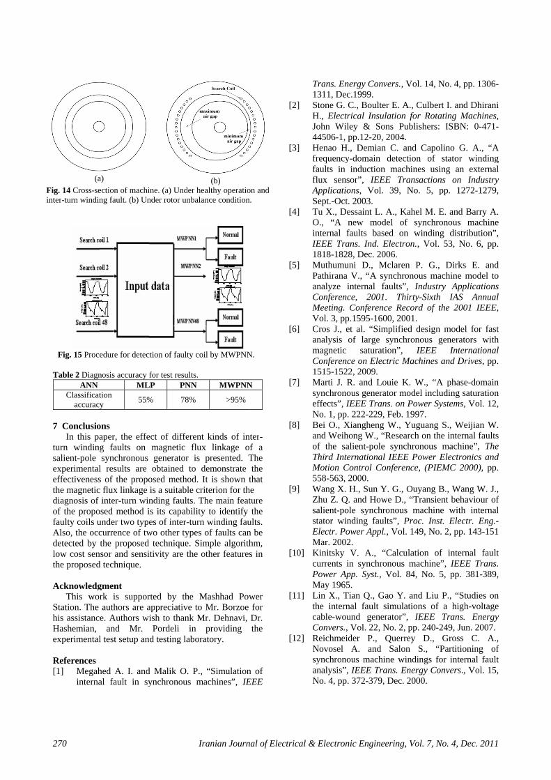
In addition, the rotor unbalance is commonly monitored in electrical machines and as the result, non-uniform flux exist in the air-gap. It must be noted when the rotor is in unbalanced condition, the length of the air-gap changes (see Fig. 14), so it reduces in one side and it increases in another side. Hence, the induced voltage in search coils at areas with less air-gap length will be increased and the induced voltage in search coils at areas with more air-gap length will be decreased.
In fact, the length of the air-gap will affect the magnitude of the induced voltage in search coils. Therefore, under rotor unbalanced conditions, forty eight induced voltages in search coils have different magnitude (under healthy operation, forty eight measured voltages have the same magnitude-see Fig. 10). While in inter-turn winding fault, the length of the air-gap is fixed (see Fig. 14) and the induced voltage in search coils at faulty area will be distorted.
(a)
(b)
Fig. 11 (a) Forty eight measured voltage (V) under turn-to-turn short circuit in the same branch in phase W (no-load). (b) Forty eight measured voltage (V) under turn-to-turn short circuit of two branches in the same phase in phase V (no-load).
(a)
(b)
Fig. 12 Forty eight measured voltage (V) under turn-to-earth fault of one path of phase V at 50% (a) Under no-load condition. (b) Under on-load condition.
Fig. 13 Forty eight measured voltage (U) under turn-to-turn short circuit of two branches in different phases in phase V and phase W (on-load). 6 Design of Fault Diagnosis System with the Aid of Neural Network
Fault detection of electrical machines has shifted in recent years from conventional techniques to Artificial Intelligence (AI) techniques. AI-based techniques have the potential advantage over the conventional methods

Yaghobi et al: Analysis of Magnetic Flux Linkage Distribution … 269
in significantly improving the accuracy in fault detection [36]. In our wok, probabilistic neural network (PNN) and discrete wavelet transform (DWT) are used in design of fault diagnosis system. PNN as main part of this fault diagnosis system and DWT are combined effectively to construct the classifier. The PNN is trained by features extracted from the magnetic flux linkage data through the discrete meyer wavelet transform. PNN is trained with simulation data and then PNN is tested with experimental data. In fact, similar to training section the measured slot flux linkage is preprocessed with wavelet transform and then in order to detect the fault, approximation signal at level 4 is fed to PNN.
6.1 Probabilistic Neural Network
PNN is a kind of the Radial Basis Function Neural Networks (RBF’s) suitable for classification problems. The PNN networks have some advantages over other artificial neural networks that are presented in the following [37]. •The PNN learns instantaneously in one-pass through the patterns of the training set which causes them faster to train, compared to other networks and these networks don’t need pre-decision on the number of layers, hidden units and initial weights. •The fast learning speed of the PNN makes it suitable for fault diagnosis and signal classification problems in real time (especially when implemented on hardware systems).
6.2 Wavelet Decomposition Many applications use the wavelet decomposition.
One of the most popular applications of the wavelet transforms is in de-noising studies on the steady state problems [38]. The aim of de-noising is to eliminate the noise and to retain the important features as much as possible. In this project, DWT is used for de-noising, because by reducing the noise, better network training is done.
6.3 Detection of Faulty Coil by MWPNN In this subsection, procedure for detection of faulty
coil by PNN and DWT, based on the previous discussion are presented. Meyer wavelet probabilistic neural network (MWPNN) is utilized to detect the faulty coils. In fact, the basic PNN is integrated with DWT to construct the MWPNN. Forty eight search coils are sampled simultaneously in one or more cycles (depending on the used hardware). Therefore, a vector sets are obtained. The obtained waveforms are analyzed by wavelet transform and de-noised signals are extracted. Then PNN is trained by features extracted from the magnetic flux linkage data through the discrete Meyer wavelet transform. In this scheme, regarding the number of search coils; forty eight MWPNN is used for detection the faulty coils. Each MWPNN is carried out only for two classes i.e., normal and fault for the classification. When no faults are present in the
generator, all MWPNN’s will predict the normal class. If some MWPNN’s predict the fault class, the turn-to-turn short circuit in the same branch or turn-to-turn short circuit of two branches in the same phase has occurred. Also, if all MWPNN’s predict the fault class, the turn-to-turn short circuit of two branches in different phases or turn-to-earth fault has occurred. This process is illustrated in Fig. 15.
Each neural network is trained with 5 input data (or events) of each class. Table 1 lists the parameters of the MWPNN in this procedure for detection of faulty coil. The influence of different kinds of mother wavelets on the classification accuracy was also investigated. It will provide the evidences for choosing proper wavelet family. Five commonly used wavelets, named Meyer wavelet, Haar wavelet, Daubechie’s wavelet, Symmlets and Coiflets wavelet are considered. In order to evaluate the performance of different kinds of mother wavelets, we choose the same decomposition level up to 6 levels. The highest classification accuracy is obtained with Meyer wavelet in level 4. Hence, in order to detect the fault, discrete meyer wavelet transform is used and the approximation signal at level 4 is fed to PNN.
Therefore, MWPNN is used as the supervised classifier. To evaluate the performance of MWPNN, its results are compared with those of different artificial neural networks. These different networks are trained and subsequently tested with the same data due to similar procedure mentioned before. These data for training are obtained from computation with the FEM. Then, the ANN’s are tested with the experimental data. These simultaneous data are sampled with those of the designed electronic-microcontroller board from the forty eight search coils in cross-section of the mentioned generator. First, fault diagnosis system uses back-propagation (BP) neural network. Second, system uses PNN and third, system uses MWPNN.
It must be noted that backpropagation neural network is most widespread among all artificial neural networks [39]. These networks are also referred to as multilayered perceptron (MLP) or feedforward networks. The multilayered perceptron neural network is trained with the Batch Gradient Descent with Momentum. In detection of the faulty coil, for the MLP neural network, several network configurations were tried. Better results have been obtained from a network composed of three layers with 240, 24, and 2 neurons. Sigmoid is selected as the act function of neurons in every layer. The results of comparison for the detection of the faulty coil are presented in Table 2.
Table 1 Parameters of the MWPNN for detection of the faulty coil.
Method Related parameter
PNN Input layer 240 nodes (depending
on the used hardware) Output layer 2 nodes
Smoothing parameter 0.5
Fin
270
(aFig. 14 Cross-senter-turn windin
Fig. 15 Proc
Table 2 DiagnANN
Classificataccuracy
7 Conclusio
In this paturn windinsalient-pole experimentaleffectivenessthe magneticdiagnosis of of the propofaulty coils uAlso, the occdetected by low cost senthe proposed Acknowledg
This worStation. The his assistancHashemian, experimental
References [1] Megah
interna
a) ection of maching fault. (b) Un
edure for detec
nosis accuracy fML
tion y 55%
ons aper, the effeg faults on synchronous
l results are s of the propoc flux linkage
inter-turn winosed method iunder two typecurrence of twthe proposed
nsor and sensid technique.
gment rk is supporauthors are ae. Authors wi
and Mr. l test setup an
hed A. I. andal fault in sy
I
ine. (a) Under hnder rotor unbal
tion of faulty c
for test results. LP PNN
% 78%
ect of differenmagnetic flugenerator isobtained to
osed method. is a suitable cnding faults. Tis its capabilites of inter-tur
wo other typestechnique. S
tivity are the
rted by the appreciative toish to thank MPordeli in
d testing labo
d Malik O. P.ynchronous m
Iranian Journ
(b) healthy operatiolance condition
oil by MWPNN
MWPNN
>95%
nt kinds of inux linkage os presented. T
demonstrate It is shown t
criterion for thThe main featty to identify rn winding faus of faults can
Simple algorithother feature
Mashhad Powo Mr. Borzoe Mr. Dehnavi,
providing ratory.
., “Simulationmachines”, IE
nal of Electric
on and n.
N.
N
nter-of a The the
that he ture the
ults. n be hm, s in
wer for Dr. the
n of EEE
[2]
[3]
[4]
[5]
[6]
[7]
[8]
[9]
[10
[11
[12
al & Electron
Trans. En1311, Dec
] Stone G. CH., ElectrJohn Wil44506-1, p
] Henao H.frequencyfaults in flux sensApplicatioSept.-Oct.
] Tu X., DeO., “A ninternal fIEEE Tra1818-1828
] MuthumuPathirana analyze iConferencMeeting. Vol. 3, pp
] Cros J., eanalysis omagnetic Conferenc1515-1522
] Marti J. Rsynchronoeffects”, INo. 1, pp.
] Bei O., Xand Weihof the saThird InteMotion C558-563, 2
] Wang X. Zhu Z. Q.salient-postator winElectr. PoMar. 2002
0] Kinitsky currents iPower ApMay 1965
1] Lin X., Tthe interncable-wouConvers.,
2] ReichmeidNovosel synchronoanalysis”,No. 4, pp.
nic Engineerin
ergy Conversc.1999. C., Boulter E.rical Insulatioley & Sons pp.12-20, 200., Demian C.
y-domain detinduction ma
sor”, IEEE Tons, Vol. 39. 2003. essaint L. A., new model faults based ans. Ind. Elec8, Dec. 2006.
uni D., MclarV., “A synch
internal faultce, 2001. TConference R
p.1595-1600, 2et al. “Simplifof large syn
saturation”ce on Electric2, 2009. R. and Louie ous generator IEEE Trans. o 222-229, Feb
Xiangheng W.ong W., “Res
alient-pole synernational IEE
Control Confer2000. H., Sun Y. G. and Howe Dle synchrononding faults”,ower Appl., Vo2. V. A., “Cal
in synchronoupp. Syst., Vol5. ian Q., Gao Y
nal fault simuund generatoVol. 22, No.
der P., QueA. and Sa
ous machine w IEEE Trans. 372-379, Dec
ng, Vol. 7, No.
s., Vol. 14, No
. A., Culbert Ion for RotatinPublishers: I
04. and Capolinection of staachines usingTransactions , No. 5, pp
Kahel M. E. of synchronon winding
ctron., Vol. 5
ren P. G., Dhronous machts”, Industry Thirty-Sixth Record of the2001. fied design m
nchronous gen”, IEEE c Machines an
K. W., “A pmodel includ
on Power Systb. 1997. , Yuguang S.
search on the inchronous mEE Power Elerence, (PIEM
G., Ouyang B.,D., “Transient ous machine , Proc. Inst. ol. 149, No. 2
lculation of ius machine”, l. 84, No. 5,
Y. and Liu P.ulations of a
or”, IEEE Tr2, pp. 240-24
errey D., Glon S., “Pawindings for Energy Conv
c. 2000.
4, Dec. 2011
o. 4, pp. 1306-
I. and Dhiraning Machines,SBN: 0-471-
no G. A., “Aator windingg an external
on Industry. 1272-1279,
and Barry A.ous machinedistribution”,3, No. 6, pp.
Dirks E. andhine model to
ApplicationsIAS Annual
e 2001 IEEE,
model for fastnerators withInternational
nd Drives, pp.
phase-domaining saturationtems, Vol. 12,
., Weijian W.internal faults
machine”, Theectronics and
MC 2000), pp.
, Wang W. J.,behaviour ofwith internalElectr. Eng.-
2, pp. 143-151
internal faultIEEE Trans.pp. 381-389,
., “Studies onhigh-voltage
rans. Energy9, Jun. 2007.
Gross C. A.,artitioning of
internal faultvers., Vol. 15,
-
i , -
A g l y ,
. e , .
d o s l ,
t h l .
n n ,
. s e d .
, f l -
t ,
n e y
, f t ,

Yaghobi et al: Analysis of Magnetic Flux Linkage Distribution … 271
[13] Rahnama M. and Nazarzadeh J., “Synchronous machine modeling and analysis for internal faults detection”, IEEE International Conference on Electric Machines & Drives (IEMDC '07), 2007.
[14] Faiz J. and Pakdelian S., “Diagnosis of static eccentricity in switched reluctance motors based on mutually induced voltages”, IEEE Trans. Energy Convers., Vol. 44, No. 8, pp. 2029-204, Aug. 2008.
[15] Vahedi A. and Behjat V., “Online monitoring of power transformers for detection of internal winding short circuit faults using negative sequence analysis”, European Transactions on Electrical Power, Vol. 15, Apr. 2010.
[16] Negrea M. D., “Electromagnetic flux monitoring for detecting faults in electrical machines”, Ph.D.dissertation, Helsinki University of Technology, Laboratory of Electromechanics, Helsinki, Finland, 2007. The dissertation can be read at http://lib.tkk.fi/Diss/isbn9512284774.
[17] Bui V. P., Chadebec O., Rouve L.-L and Coulomb J.-L., “Noninvasive fault monitoring of electrical machines by solvingthe steady-state magnetic inverse problem”, IEEE Trans. Magn., Vol. 44, No. 6, pp. 1050-1053, Jun. 2008.
[18] Joksimovic G. M. and Penman J., “The detection of inter-turn short circuits in the stator windings of operating motors”, IEEE Trans. Ind. Electron., Vol. 47, No. 5, pp. 1078-1084, 2000.
[19] Assaf T., Henao H. and Capolino G. A., “Simplified axial flux spectrum method to detect incipient stator inter-turn short-circuits in induction machine”, IEEE International Symposium on Industrial Electronics, Vol. 2, pp. 815-819, May 2004.
[20] Yazidi A., Thailly D., Henao H., Romary R., Capolino G. A. and Brudny J. F., “Detection of stator short-circuit in induction machines using an external leakage flux sensor”, IEEE International Conference on Industrial Technology–ICIT '04, Hammamet, Tunisia, Vol. 1, pp. 166-169, Dec. 2004.
[21] Han S. B., Hwang D. H., Yi S. H. and Kang D. S., “Development of Diagnosis Algorithm for Induction Motor Using Flux Sensor”, International Conference on Condition Monitoring and Diagnosis, Beijing, China, 2008.
[22] Toni K., Slobodan M. and Aleksandar B., “Detection Of Turn To Turn Faults In Stator Winding With Axial Magnetic Flux In Induction Motors”, IEEE International Conference on Electric Machines & Drives, (IEMDC '07), Vol. 1, pp. 826-829, 2007.
[23] Mirafzal B., Povinelli R. J. and Demerdash N. A. O., “Inter-turn fault diagnosis in induction motors using the pendulous oscillation phenomenon”, IEEE Trans. Energy Convers., Vol. 21, No. 4, pp. 871-882, Dec. 2006.
[24] Nandi S., Toliyat H. A. and Li X., “Condition monitoring and fault diagnosis of electrical machines- A Review”, IEEE Trans. Energy Convers.,Vol. 20, No. 4, pp. 719-729, Dec. 2005.
[25] Ranlof M., Perers R. and Lundin U., “On Permeance modeling of large hydrogenerators with application to voltage harmonics prediction”, IEEE Trans. Energy Conversion, Vol. 25, No. 4, pp. 1179-1186, Dec. 2010.
[26] Lipo T. A., Introduction to AC Machine Design, Power Electronics Research Center, University of Wisconsin, pp. 64-82, 2004.
[27] Ahmed A. S., Yeh C. C., Demerdash N. A. O. and Mirafzal B., “Analysis of stator winding inter-turn short-circuit faults in induction machines for identification of the faulty phase”, IEEE, Industry Applications Conference, 41st IAS Annual Meeting, Vol. 3, pp. 1519-1524, Oct. 2006.
[28] Chan T. F., Wang W. and Lai L. L., “Performance of an axial-flux permanent magnet synchronous generator from 3-D finite-element analysis”, IEEE Trans. Energy Convers., Vol. , No. 99, pp. 1-8, 2010.
[29] Thailly D., Romary R. and Brudny J. F., “Quantitative analysis of the external radial magnetic field for detection of stator inter-turn short-circuit in induction machines”, IEEE, European Conference on Power Electronics and Applications, 2005.
[30] Lenz J. and Edelstein A. S., “Magnetic Sensors and Their Applications”, IEEE Sensors Journal, Vol. 6, No. 3, pp. 631-649, Jun. 2006.
[31] Tavner P. J., Gaydon B. G. and Ward B. A., “Monitoring generators and large motors”, IEE proceedings, Vol. 133Pt.B, No. 3, pp.169-180, May 1986.
[32] Xuan M. T., Simond J. J., Wetter R. and Keller S., “A novel air-gap monitoring system for large low speed hydro-generators”, IEEE, Power Engineering Society General Meeting, pp. 1-8, 2006.
[33] Klempner G. and Kerszenbaum I., Operation and maintenance of large turbo-generators, John Wiley & Sons Publishers, IEEE Press, the Institute of Electrical and Electronics Engineers, pp. 143-146, 2004.
[34] Cabanas M. F., Glez F. P., González M. R., Melero M. G., Orcajo G. A., Cano J. M. and Rojas C. H., “A new on-line method for the early detection of broken rotor bars in asynchronous motors working under arbitrary load conditions”, Industry Applications Conference, Fourtieth IAS Annual Meeting, Vol. 1, pp. 662-669, Oct. 2005.
[35] Chari M. V. K., “Nonlinear finite element solution of electrical machines under no-load and full-load conditions”, IEEE Trans. Magn., Vol. 10, No. 3, pp. 686-689, Sep. 1974.

272
[36] Hariri ImprovUncertIdentifElectropp. 79
[37] GhodsDemanFunctiElectriVol. 6
[38] RajbhaM., “PNeuralDiffusPresenJourna(IJEEE
[39] Moosageneraneural Electropp. 1-1
M., Shokouhved Fuzzy Ntainty in fication”, Iranonic Enginee-93, July 2008
s L. and Kalnd Forecastinion Neural Nical & Elec, No. 3, pp. 17andari S., GhPerformance l Network B
se Indoor Once of Artificial of ElectricE), Vol. 5, Noavienia A. alized ABFT t
network”, Ironic Enginee10, Jan. 2005.
I
hi S. B. and MNeural NetwoPattern Clanian Journal
ering (IJEEE)8. lantar M., “Lng by Usin
Networks”, Iratronic Engin75-182, Sep. 2hassemlooy Z
of the WavBased ReceiveOptical Wireal Light Interf
cal & Electroo. 2, pp. 102-1
and Mohamtechnique usinranian Journaering (IJEEE)
Iranian Journ
Mozayani N., “ork for Solv
assification of Electrical
, Vol. 4, No
Long-Term Png Radial Banian Journaneering (IJEE2010. Z. and Angelvelet Transfoer for DPIMeless Links ference”, Iranonic Engineer11, Jun. 2009
mmadi K.,ng a fault toleral of Electrica, Vol. 1, No
nal of Electric
“An ving and l & . 3,
Peak asis l of
EE),
lova orm-
M in in
nian ring 9.
“A rant
al & . 1,
of IranPow
engCom
GereleinteInte
al & Electron
Electrical Engn in 2011. Hiswer System Op
gineering in Fermputational Ele
rmany in 2002ctrical engineeerests are Poelligent System
nic Engineerin
Hamid Yagon 1978. HeElectrical EUniversity Tehran, IranEngineering2002, Mashelectric mac
ineering of Fes research inter
peration and Inte
Kourosh AIran in 195M.Sc. degrTabriz, IrEngineeringelectric macof ElectricUniversity, been an ass
rdowsi Universectromagnetic a
Habib RaMashhad, B.Sc. andfrom FerdMashhad, EngineerinDepartmenEngineerinTehran, IrAachen U
2. He has beeering in Ferdowower System
ms and Biologic
ng, Vol. 7, No.
ghobi was bore received his BEngineering fro
of Technolon, M.Sc degre
g from Ferdowshhad, Iran andchinery from thrdowsi Univerrests are Electelligent System
Ansari was bo1. He received
rees from Tabrran, both g and his Ph.Dchinery from thcal EngineerinJjiang, China insistant professosity. His researcand Electric ma
ajabi MashhadIran in 1967. H
d M.Sc. degreedowsi Universit
Iran, both ng and his Phnt of Electrical ng of Tehraran under joint University ofen an associatewsi University
Operation anal Computation
4, Dec. 2011
rn in Sari, IranB.Sc. degree inom K.N.Toosi
ogy in 2000,e in Electrical
si University ind his Ph.D. inhe Departmentsity, Mashhad,tric machinery,
ms.
orn in Urmiye,d his B.Sc. andriz University,in Electrical
D. in especiallyhe Departmentng of Jjiangn 1996. He hasor of electricalch interests areachinery.
di was born inHe received hises with honourty of Mashhad,
in Electricalh.D. from theand Computer
an University,cooperation of
f Technology,e professor of
y. His researchnd Dynamics,n.
n n i , l n n t , ,
, d , l y t g s l e
n s r , l e r , f , f h ,


![z, [5]...(b) Draw the phasor diagram of an over-excited non-salient pole synchronous motor having per phase z,=ra +jxs. [5] (c) Draw the phasor diagram of salient pole over excited](https://static.fdocuments.in/doc/165x107/609339e08132dc4c4d4cea7e/z-5-b-draw-the-phasor-diagram-of-an-over-excited-non-salient-pole-synchronous.jpg)