Analysis of laminated shear-flexible angle-ply plates
14
Analysis of laminated shear-flexible angle-ply plates Reaz A. Chaudhuri * Department of Materials Science & Engineering, University of Utah, 1222 S. Central Campus Drive, Room 304, Salt Lake City, UT 84112-0560, USA Available online 27 February 2004 Abstract A recently developed C 0 -type triangular composite plate element, based on the assumption of transverse inextensibility and layerwise constant shear-angle theory (LCST), is utilized to analyze antisymmetric and symmetric angle-ply plates subjected to distributed transverse loading. Effect of numerical integration on the rate of convergence of displacements and moments is inves- tigated in detail. Comparison of the numerical results computed using the present triangular element with their analytical coun- terparts based on the classical lamination theory (CLT) in the thin plate regime also forms a major part of the present investigation. Limited comparisons with the first-order shear deformation theory (FSDT) results, computed using assumed stress hybrid finite elements, are also presented. Numerical results presented also include the effect of fiber orientation angle on the displacements and moments for thin laminates. Finally, the effect of thickness on the computed transverse displacement (deflection), interfacial inplane displacement and inplane stress is also thoroughly investigated. Ó 2004 Elsevier Ltd. All rights reserved. Keywords: Anisotropic; Angle-ply; Composite; Laminate; Layerwise constant shear-angle theory (LCST); First-order shear deformation theory (FSDT); Classical lamination theory (CLT); Interlaminar shear deformation; Thick plate; Triangular element; Scaling effect 1. Introduction Recent years have witnessed an increasing use of advanced composite materials (e.g., graphite/epoxy, boron/epoxy, Kevlar/epoxy, graphite/PEEK, etc.), which are replacing metallic alloys in the fabrication of load-bearing plate-type structures because of many beneficial properties, such as higher strength-to-weight ratios, longer fatigue (including sonic fatigue) life, better stealth characteristics, enhanced corrosion resis- tance, and, most significantly, the possibility of optimal design through the variation of stacking pattern, fiber orientation, and so forth, known as composite tailor- ing. The advantages that accrue from these properties are, however, not attainable without paying for the complexities that are introduced by various coupling effects. Furthermore, since the matrix material is of relatively low shearing stiffness as compared to the fi- bers, a reliable prediction of the response of these laminated shells must account for interlaminar (trans- verse) shear deformation or cross-sectional warping of individual layers, in contrast to the Kirchhoff or Mindlin hypothesis. The former, known as the classical lamination theory (CLT), neglects the interlaminar shear deformation altogether, while the latter, called the first-order shear deformation theory (FSDT) as- sumes constant transverse shear deformation through the entire thickness of the laminate. More recently, various refined or higher-order shear deformation the- ory (HSDT) based solutions have become available in the literature. Basset [1] appears to have been the first to suggest that the in-plane displacements can be ex- panded in power series of the thickness coordinate. Following Basset’s lead, second- and higher-order shear deformation theories (HSDT), assuming transverse in- extensibility and continuous inplane displacements through the thickness of thick laminates, have been developed as special cases of the above, e.g., Refs. [2,3]. A detailed review of the literature and a double Fourier series solution to a general type boundary-value prob- lem pertaining to HSDT-based laminates are available in Chaudhuri and Kabir [4]. Noor and Burton [5] have presented extensive surveys on shear deformation theories and computational mod- els relating to laminated plates. Exact three-dimensional elasticity solutions for rectangular cross-ply plates for a specific type of simply supported boundary condi- tion are due to Pagano [6], and Srinivas and Rao [7]. Approximate thick laminate theories can be classified * Tel.: +1-801-581-6863; fax: +1-801-581-4816. E-mail address: [email protected] (R.A. Chaudhuri). 0263-8223/$ - see front matter Ó 2004 Elsevier Ltd. All rights reserved. doi:10.1016/j.compstruct.2004.01.002 Composite Structures 67 (2005) 71–84 www.elsevier.com/locate/compstruct
-
Upload
reaz-a-chaudhuri -
Category
Documents
-
view
231 -
download
1
Transcript of Analysis of laminated shear-flexible angle-ply plates
Composite Structures 67 (2005) 71–84
www.elsevier.com/locate/compstruct
Analysis of laminated shear-flexible angle-ply plates
Reaz A. Chaudhuri *
Department of Materials Science & Engineering, University of Utah, 1222 S. Central Campus Drive, Room 304, Salt Lake City, UT 84112-0560, USA
Available online 27 February 2004
Abstract
A recently developed C0-type triangular composite plate element, based on the assumption of transverse inextensibility and
layerwise constant shear-angle theory (LCST), is utilized to analyze antisymmetric and symmetric angle-ply plates subjected to
distributed transverse loading. Effect of numerical integration on the rate of convergence of displacements and moments is inves-
tigated in detail. Comparison of the numerical results computed using the present triangular element with their analytical coun-
terparts based on the classical lamination theory (CLT) in the thin plate regime also forms a major part of the present investigation.
Limited comparisons with the first-order shear deformation theory (FSDT) results, computed using assumed stress hybrid finite
elements, are also presented. Numerical results presented also include the effect of fiber orientation angle on the displacements and
moments for thin laminates. Finally, the effect of thickness on the computed transverse displacement (deflection), interfacial inplane
displacement and inplane stress is also thoroughly investigated.
� 2004 Elsevier Ltd. All rights reserved.
Keywords: Anisotropic; Angle-ply; Composite; Laminate; Layerwise constant shear-angle theory (LCST); First-order shear deformation theory
(FSDT); Classical lamination theory (CLT); Interlaminar shear deformation; Thick plate; Triangular element; Scaling effect
1. Introduction
Recent years have witnessed an increasing use of
advanced composite materials (e.g., graphite/epoxy,
boron/epoxy, Kevlar/epoxy, graphite/PEEK, etc.),
which are replacing metallic alloys in the fabrication of
load-bearing plate-type structures because of many
beneficial properties, such as higher strength-to-weight
ratios, longer fatigue (including sonic fatigue) life,better stealth characteristics, enhanced corrosion resis-
tance, and, most significantly, the possibility of optimal
design through the variation of stacking pattern, fiber
orientation, and so forth, known as composite tailor-
ing. The advantages that accrue from these properties
are, however, not attainable without paying for the
complexities that are introduced by various coupling
effects. Furthermore, since the matrix material is ofrelatively low shearing stiffness as compared to the fi-
bers, a reliable prediction of the response of these
laminated shells must account for interlaminar (trans-
verse) shear deformation or cross-sectional warping of
individual layers, in contrast to the Kirchhoff or
Mindlin hypothesis. The former, known as the classical
* Tel.: +1-801-581-6863; fax: +1-801-581-4816.
E-mail address: [email protected] (R.A. Chaudhuri).
0263-8223/$ - see front matter � 2004 Elsevier Ltd. All rights reserved.
doi:10.1016/j.compstruct.2004.01.002
lamination theory (CLT), neglects the interlaminarshear deformation altogether, while the latter, called
the first-order shear deformation theory (FSDT) as-
sumes constant transverse shear deformation through
the entire thickness of the laminate. More recently,
various refined or higher-order shear deformation the-
ory (HSDT) based solutions have become available in
the literature. Basset [1] appears to have been the first
to suggest that the in-plane displacements can be ex-panded in power series of the thickness coordinate.
Following Basset’s lead, second- and higher-order shear
deformation theories (HSDT), assuming transverse in-
extensibility and continuous inplane displacements
through the thickness of thick laminates, have been
developed as special cases of the above, e.g., Refs. [2,3].
A detailed review of the literature and a double Fourier
series solution to a general type boundary-value prob-lem pertaining to HSDT-based laminates are available
in Chaudhuri and Kabir [4].
Noor and Burton [5] have presented extensive surveys
on shear deformation theories and computational mod-
els relating to laminated plates. Exact three-dimensional
elasticity solutions for rectangular cross-ply plates for
a specific type of simply supported boundary condi-
tion are due to Pagano [6], and Srinivas and Rao [7].Approximate thick laminate theories can be classified
Nomenclature
a, b length and width of a laminated plate
½Bj� strain–nodal displacement relation matrix for
the jth composite plate element½CðiÞ�, ½GðiÞ� elastic stiffness matrices of the ith aniso-
tropic lamina in inplane stretching/shear and
transverse shear, respectively
fdjg nodal displacement vector of the jth com-
posite plate element�di distance from the bottom (reference) surface
E1, E2 Young’s moduli of an orthotropic lamina in
the direction of fibers and normal to the fi-bers, respectively
Fj consistent load vector of the jth composite
plate element
G12 inplane shear modulus of an orthotropic
lamina
G13, G23 transverse shear moduli of an orthotropic
lamina
½Kj� stiffness matrix for the jth composite plateelement
N total number of layers or laminae
Nd number of subdivisions in a finite element
model
q0 applied uniformly distributed load (normal
pressure) on the top surface of a laminated
plate
qjðx1; x2Þ applied surface load on the top surface ofthe jth composite plate element
ti, t thickness of the ith lamina and laminated
plate, respectively
U strain energy of a laminated plate
U strain energy per unit area
U ðiÞB strain energy in bending and twisting of the
ith layer
U ðiÞS strain energy in transverse (interlaminar)
shear of the ith layer
ui components of the displacement vector,
i ¼ 1; 2; 3W potential due to external conservative forces
w deflection of a plate
xi cartesian coordinates, i ¼ 1; 2; 3cðiÞ12 inplane (engineering) shearing strain at a
point inside the ith layer
cðiÞ13, cðiÞ23 transverse (engineering) shearing strains at a
point inside the ith layer
Dj reference surface area of the jth element
eðiÞk‘ inplane components of the strain tensor at a
point inside the ith layer; k; ‘ ¼ 1; 2m12, m13, m23 major Poisson’s ratios of an orthotropic
lamina
P total potential energy functional
�sðNþ1Þ13 , �sðNþ1Þ
23 , �rðNþ1Þ33 , �sð1Þ13 , �s
ð1Þ23 , �r
ð1Þ33 applied distributed
forces over the top and bottom surfaces of a
N -layer plate
�rðiÞnnðx3Þ, �s
ðiÞnCðx3Þ, �s
ðiÞn3ðx3Þ applied forces at a boundary
distributed through the thickness of the ithlayer
f/g shape functions
72 R.A. Chaudhuri / Composite Structures 67 (2005) 71–84
into two categories: (a) discrete layer approach, and (b)
continuous inplane displacement through thickness, e.g.
the CLT, FSDT and HSDT, mentioned above. The
former approach, e.g., the layerwise constant shear-angle
theory (LCST) or the zig-zag theory, first introduced by
Mau et al. [8] appears to be quite suitable for numerical
methods, such as the degenerate type finite element
methods (FEM), although a number of analyses onshear-flexible laminated plates have been performed
using FSDT-based finite elements, e.g., Spilker et al. [9].
Seide [10] has utilized the LCST in the derivation of an
exact solution to an infinitely long laminated strip
problem.
The LCST-based solution due to Mau et al. [8] for
laminated thick plates has used a quadrilateral element
shape, and assumed stress hybrid finite element method(FEM). Although this method has yielded results for
certain simpler laminated plate problems, it suffers from
certain difficulties, such as the presence of spurious
kinematic modes [11]. More recently, Chaudhuri and
Seide [12], and Seide and Chaudhuri [13] have developed
a quadratic triangular element, based on the LCST, and
an assumed displacement potential energy approach, for
analyses of laminated plates and shells, respectively.
Example problems analyzed by Chaudhuri and Seide
[12] include a symmetric cross-ply [90�/0�/90�] infinitelylong strip and a three-layer symmetric cross-ply square
plate. Additionally, the special case of a homogeneousisotropic plate has been presented by Chaudhuri [14].
LCST-based results on angle-ply plates, computed using
this triangular element, are not available in the litera-
ture, which is the primary objective of the present
investigation. The specific goals of the present analysis,
which assumes quadratic shape functions, are to (i)
obtain satisfactory convergence of displacements and
moments, (ii) study the effect of triangulation pattern onconvergence, (iii) investigate the effect of numerical
integration on convergence, and (iv) study the effects of
fiber orientation angle and length-to-thickness ratio on
computed displacements and stresses (or moments).
R.A. Chaudhuri / Composite Structures 67 (2005) 71–84 73
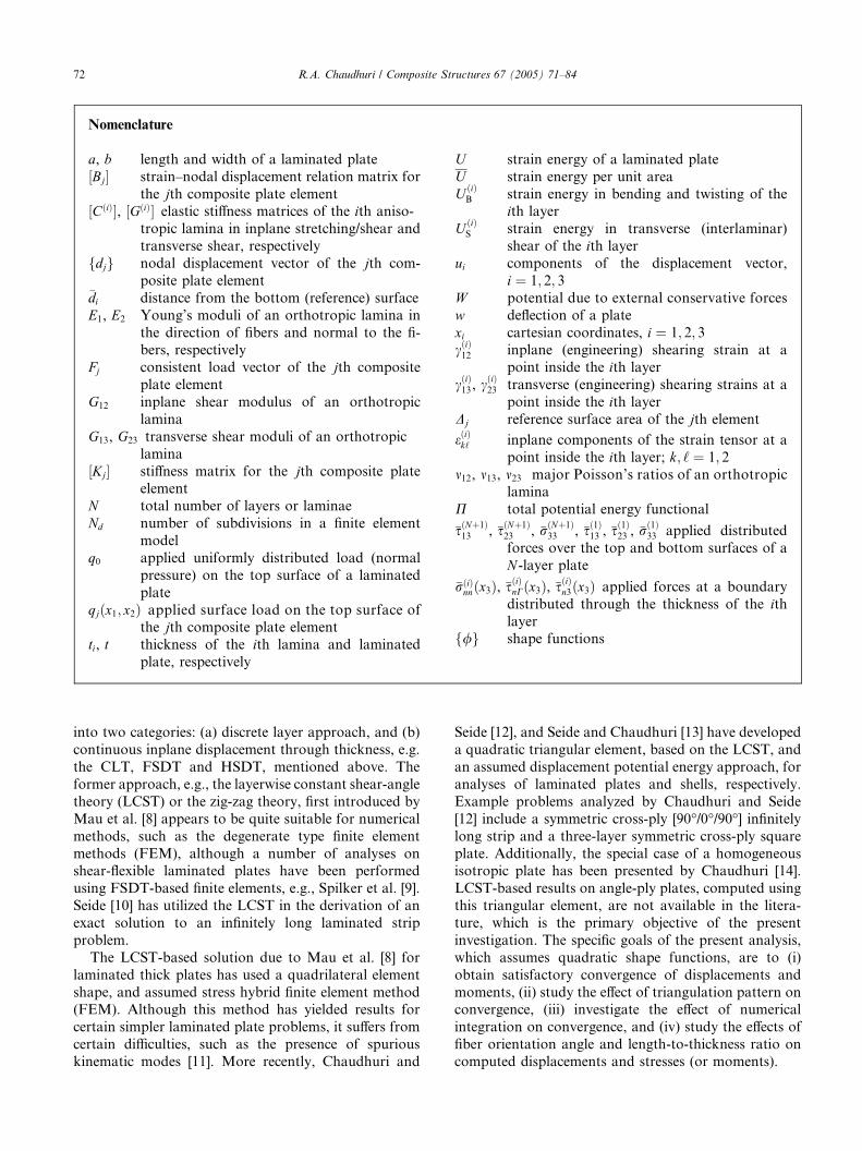
2. Theoretical background and finite element formulation
Fig. 1 shows a N -layer laminated composite trian-
gular element with its bottom surface designated as thereference surface. The local or element coordinates are
denoted by xa, a ¼ 1; 2; 3, while the corresponding glo-
bal or plate coordinates are represented by x, y, z. Thebasic assumptions underlying the formulation of a
laminated thick plate element, based on discrete layer or
zig-zag approach are: (i) small deformation, (ii) linear
anisotropic elasticity, (iii) transverse inextensibility and
(iv) layerwise constant shear angle hypothesis. By virtueof these assumptions, the inplane strains at a point in-
side the ith lamina are given as follows [12]:
eðiÞðx3Þ� �
¼ AðiÞb ðx3Þ
h iAðiÞt ðx3Þ
h ih i �eðiÞn o�eðiþ1Þn o
8<:
9=;; ð1Þ
in which ½AðiÞb ðx3Þ� and ½AðiÞ
t ðx3Þ� are as given by Eq. (A.1)in the Appendix A, while
eðiÞðx3Þ� �T ¼ eðiÞ11ðx3Þ eðiÞ22ðx3Þ cðiÞ12ðx3Þ
� �;
for i ¼ 1; . . . ;N ; ð2aÞ
and
�eðiÞn oT
¼ �eðiÞ11 �eðiÞ22 �cðiÞ12
n o; for i ¼ 1; . . . ;N þ 1:
ð2bÞ
The interlaminar or transverse shear strains in the ithlamina given by
cðiÞ� �T ¼ cðiÞ13 cðiÞ23
n o; for i ¼ 1; . . . ;N ð3Þ
do not vary with x3 within a lamina. The transverse
shear strain components, cðiÞk3 , k ¼ 1; 2, can be written as
cðiÞk3 ¼ �u3;k þ1
tið�uðiþ1Þ
k � �uðiÞk Þ: ð4Þ
The total potential energy of the N -layer laminated
anisotropic plate can now be written as follows:
P ¼ U þ W ; ð5Þ
Fig. 1. (a) A laminated composite plate element of triangular plan-
form. (b) A layer element.
where U , the strain energy, is given by
U ¼XNi¼1
ðU ðiÞB þ U ðiÞ
S Þ; ð6Þ
in which the bending contribution to the lamina strain
energy is given as follows:
U ðiÞB ¼ 1
2
Zx2
Zx1
Zx3
eðiÞðx3Þ� �T½CðiÞ� eðiÞðx3Þ
� �dx3 dx1 dx2;
ð7aÞ
and the corresponding interlaminar or transverse shear
contribution is
U ðiÞS ¼ 1
2
Zx2
Zx1
Zx3
cðiÞðx3Þ� �T½GðiÞ� cðiÞðx3Þ
� �dx3 dx1 dx2;
ð7bÞ
where ½CðiÞ� and ½GðiÞ�, the lamina elastic stiffness matri-
ces as described by Eqs. (A.3a) and (A.3b), respectively,
are related to Young’s and shear moduli, and Poisson’s
ratios.
With the lamina strain–displacement and constitutiverelations given by Eqs. (1)–(4) and (A.3), respectively,
the strain energy for the laminated plate can be written
from Eqs. (6) and (7), on integration with respect to x3,as
U ¼Zx2
Zx1
U dx1 dx2; ð8Þ
wherein U , the strain energy of the laminated plate per
unit area of the reference (bottom) surface, is given by
U ¼ 1
2f�egT½D�f�eg; ð9Þ
in which
f�egT ¼ f�eg fcg� �
; ð10Þ
with
f�egT ¼ �eð1Þn oT
� � � �eðiÞn oT
� � � �eðNþ1Þn oT
� �;
ð11aÞ
and
fcgT ¼ cð1Þ� �T � � � fcðiÞgT � � � fcðNÞgT
n o: ð11bÞ
For a N -layer plate, ½D� is a ð5N þ 3Þ � ð5N þ 3Þ matrix
given by Eqs. (A.4)–(A.6).
If the applied surface and edge forces are conserva-
tive, the potential due to these forces is given by

74 R.A. Chaudhuri / Composite Structures 67 (2005) 71–84
W ¼ �Z Z
Sð�sðNþ1Þ
13 �uðNþ1Þ1
hþ �sðNþ1Þ
23 �uðNþ1Þ2
þ �rðNþ1Þ33 �uðNþ1Þ
3 Þ � ð�sð1Þ13 �uð1Þ1 þ �sð1Þ23 �u
ð1Þ2
þ �rð1Þ33 �u
ð1Þ3 ÞidS �
ZC0
XNi¼1
Z �diþ1
x3¼di
½�sðiÞnCðx3ÞuðiÞC ðx3Þ
þ �rðiÞnnðx3ÞuðiÞn ðx3Þ þ �sðiÞn3ðx3Þu
ðiÞ3 �dx3 dC; ð12Þ
in which
�di ¼Xi�1
m¼1
tm; �d1 ¼ 0; �dNþ1 ¼ t: ð13Þ
The quadratic shape function used for the triangular
element is best expressed in terms of area coordinates as
shown below:
f/gT ¼ f1ð2f1 � 1Þ 4f1f2 f2ð2f2 � 1Þ 4f2f3 f3ð2f3 � 1Þ 4f3f1f g; ð14Þ
where fk, k ¼ 1; 2; 3 represents area coordinates [15].
Finally, the strain energy of the jth triangular element
can be written in the form [12]:
Uj ¼1
2fdjgT½Kj�fdjg; ð15Þ
in which the corresponding element stiffness matrix is
given by
½Kj� ¼ZDj
Z½½Bj�T½Dj�½Bj��dD; ð16Þ
where ½Bj� is a matrix given by Eqs. (A.7)–(A.11), while
fdjg is a column vector, given as follows:
fdjgT ¼ ð�u1Þð1Þ1 ð�u2Þð1Þ1 � � � ð�u1Þð1Þ6 ð�u2Þð1Þ6 � � � ð�u1ÞðNÞ6 ð�u2ÞðNÞ
6 ðu3Þ1 � � � ðu3Þ6n o
: ð17Þ
Fig. 2. A rectangular laminated plate.
The subscripts outside the parentheses on the right side
of Eq. (17) represent the kth node of the element inter-
face for k ¼ 1; . . . ; 6.Similar operations as above on Eq. (12) yield the
potential due to applied conservative forces on the top
and bottom surfaces of the plate element as well as those
acting on its edge through its thickness. For example,
the potential due to distributed normal load acting onthe top surface of the jth element of the N -layer plate is
obtained by substituting
�rðNþ1Þ33 ¼ qjðx1; x2Þ; ð18aÞ
and
�rð1Þ33 ¼ �sð1Þ13 ¼ �sð1Þ23 ¼ �sðNþ1Þ
13 ¼ �sðNþ1Þ23 ¼ �rðiÞ
nnðx3Þ
¼ �sðiÞnCðx3Þ ¼ �sðiÞn3ðx3Þ ¼ 0; for i ¼ 1; . . . ;N ; ð18bÞ
into Eq. (12), yielding
Wj ¼ �fdjgTfFjg; ð19Þ
where fFjg, the consistent load vector of the jth com-
posite-element, is given by
fFjgT ¼ f0g fPgj� �
; ð20Þ
in which {0} is a 12ðN þ 1Þ null row-vector, while fPgj isa 6-element row-vector, given by
fPgj ¼ P1j � � � Pkj � � � P6jf g; ð21Þ
with
Pkj ¼1
2
ZDj
Zqjðx1; x2Þ/kðx1; x2ÞdD; for
j ¼ 1; . . . ;N ; k ¼ 1; . . . ; 6: ð22Þ
3. Numerical results and discussions
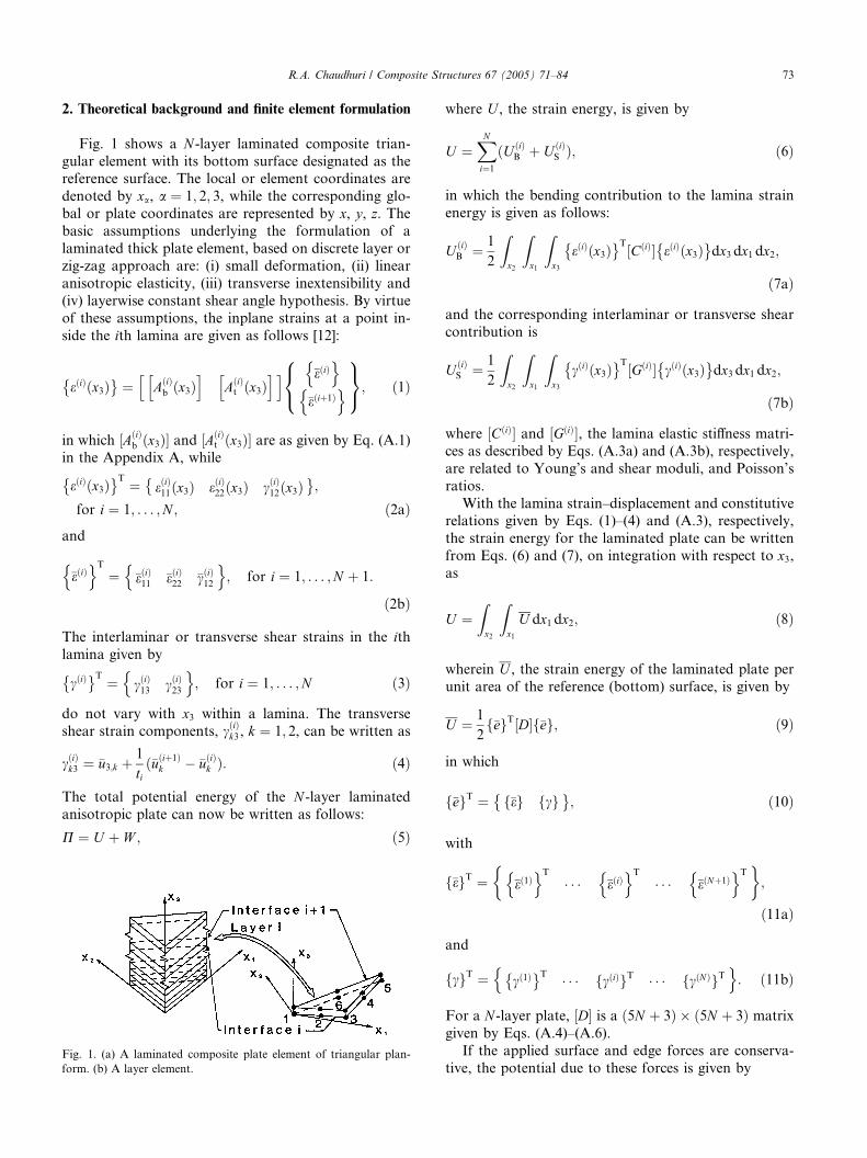
Fig. 2 shows a laminated rectangular plate. The fol-
lowing example problems, pertaining to the deformation
of square (a ¼ b ¼ 25:4 cm (10 in)) angle-ply plates

Fig. 3. Finite element mesh for a square ±45� plate.
R.A. Chaudhuri / Composite Structures 67 (2005) 71–84 75
subjected to uniform transverse load, q0, will serve to
not only illustrate the validity of the finite element
procedure presented in the preceding section, but also
present hitherto unavailable benchmark numericalsolutions. The following material (lamina) properties for
a representative high modulus fiber reinforced compos-
ite are considered:
E1
E2
¼ 40;G12
E2
¼ G13
E2
¼ G23
E2
¼ 0:5; m12 ¼ m13 ¼ m23 ¼ 0:25;
where E1 and E2 represent the inplane Young’s moduli
in the x1 and x2 directions, respectively, while m12 is the
inplane major Poisson’s ratio, and m13 and m23 denote thesame in the x1–x3 and x2–x3 planes, respectively. G12
denotes the inplane shear modulus, while G13 and G23
represent the transverse shear moduli in the x1–x3 and
x2–x3 planes, respectively. Before proceeding to compute
the numerical results for angle-ply laminates, the
numerical results for cross-ply plates [12] have been
reproduced first, which lends some credence to the
accuracy of what follows. The following normalized
quantities are defined:
�w ¼ 103E2ðt=NÞ3
�q0a4w; ð23aÞ
�u ¼ 10E2ðt=NÞ2
�q0a3u; ð23bÞ
ð�rðiÞx ; �rðiÞ
y �sðiÞxy Þ ¼
10ðt=NÞ2
�q0a2ðrðiÞ
x ; rðiÞy sðiÞxy Þ; ð23cÞ
ðMx;MyÞ ¼10
�q0a2ðMx;MyÞ; ð23dÞ
in which �q0 ¼ q0, for a two-layer balanced antisymmet-
ric angle-ply plate, while �q0 ¼ q0=2, for a three-layerunbalanced symmetric angle-ply laminate numerically
investigated below.
3.1. Example 1: Two-layer antisymmetric angle-ply plates
under uniform pressure
As an important check on the accuracy of the trian-
gular element under consideration, the problem of a
uniformly loaded two-layer antisymmetric balanced
angle-ply ð��hÞ plate is investigated in detail. The layers
are of equal thickness, t=2. The plate is simply supported
on all four edges so that transverse displacements there
vanish. Normal and parallel edge inplane displacements
at the top and bottom surfaces of the plate are free tooccur. Whitney [16] has solved the same problem using
the classical lamination theory (CLT) in which the effect
of transverse shear deformation is neglected. Spilker
et al. [9] have obtained solutions using the assumed
stress hybrid finite element method based on the first
order shear deformation theory (FSDT), and have
achieved, by modeling with quadrilateral elements,
reasonably close agreement with a corrected version of
Whitney’s [16] results. However, as will also be seen
below, their triangular elements do not yield results of
desired accuracy.Because of apparent lack of symmetry conditions due
to the coupling of bending and inplane shear (or
equivalently, twisting–extension coupling), the entire
plate has to be modeled except for h ¼ �45�, in which
case only half the plate is modeled (Fig. 3).
3.2. Triangulation pattern
Before investigating the convergence of the present
triangular element, it is important to determine which
geometrical configuration or triangulation pattern yields
superior performance with the same number of degreesof freedom. Two triangulation patterns are possible: (a)
unidirectional diagonals (Fig. 4a) and (b) bi-directional
diagonals (Fig. 4b). Strang and Fix [17] have invoked
the following theorem, which states that: If Sh is of de-
gree k0 � 1 on a regular mesh, there exist non-negative
definite matrices K, such that for every u in Hk0
h2ðs0�k0Þmin
Sh
ju�uhj2s0 !
Xja0 j¼jb0 j¼k0
Ka0b0
S0
ZðDa0uÞ
ZðDb0uÞdx;
ð24Þ
and have shown for the two-dimensional case that the
pattern (a) is superior to the pattern (b) by a factor of
1.25. This is tested here via a numerical experiment for
the two-layer ±45� angle-ply laminate using a 2 · 2 mesh
and quintic order of quadrature. The numerical experi-
ment favors the pattern (a) over (b) by a factor of 1.68.
Since both the theory and numerical experiment favorsthe pattern with unidirectional diagonals, the results
presented here are computed using this pattern only.
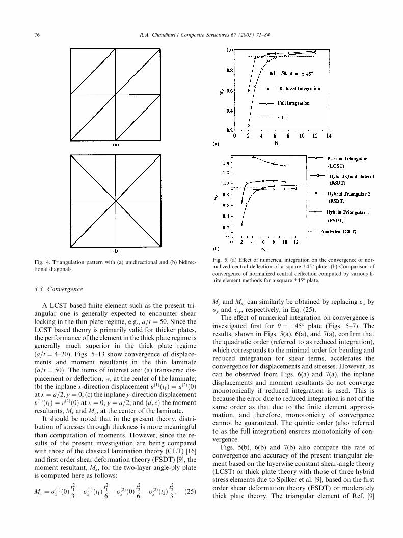
Fig. 4. Triangulation pattern with (a) unidirectional and (b) bidirec-
tional diagonals.
Fig. 5. (a) Effect of numerical integration on the convergence of nor-
malized central deflection of a square ±45� plate. (b) Comparison of
convergence of normalized central deflection computed by various fi-
nite element methods for a square ±45� plate.
76 R.A. Chaudhuri / Composite Structures 67 (2005) 71–84
3.3. Convergence
A LCST based finite element such as the present tri-
angular one is generally expected to encounter shear
locking in the thin plate regime, e.g., a=t ¼ 50. Since the
LCST based theory is primarily valid for thicker plates,
the performance of the element in the thick plate regime isgenerally much superior in the thick plate regime
(a=t ¼ 4–20). Figs. 5–13 show convergence of displace-
ments and moment resultants in the thin laminate
ða=t ¼ 50Þ. The items of interest are: (a) transverse dis-
placement or deflection, w, at the center of the laminate;
(b) the inplane x-direction displacement uð1Þðt1Þ ¼ uð2Þð0Þat x ¼ a=2, y ¼ 0; (c) the inplane y-direction displacement
vð1Þðt1Þ ¼ vð2Þð0Þ at x ¼ 0, y ¼ a=2; and ðd; eÞ the momentresultants, Mx and My , at the center of the laminate.
It should be noted that in the present theory, distri-
bution of stresses through thickness is more meaningful
than computation of moments. However, since the re-
sults of the present investigation are being compared
with those of the classical lamination theory (CLT) [16]
and first order shear deformation theory (FSDT) [9], the
moment resultant, Mx, for the two-layer angle-ply plateis computed here as follows:
Mx ¼ rð1Þx ð0Þ t
21
3þ rð1Þ
x ðt1Þt216� rð2Þ
x ð0Þ t22
6� rð2Þ
x ðt2Þt223; ð25Þ
My and Mxy can similarly be obtained by replacing rx by
ry and sxy , respectively, in Eq. (25).
The effect of numerical integration on convergence is
investigated first for �h ¼ �45� plate (Figs. 5–7). Theresults, shown in Figs. 5(a), 6(a), and 7(a), confirm that
the quadratic order (referred to as reduced integration),
which corresponds to the minimal order for bending and
reduced integration for shear terms, accelerates the
convergence for displacements and stresses. However, as
can be observed from Figs. 6(a) and 7(a), the inplane
displacements and moment resultants do not converge
monotonically if reduced integration is used. This isbecause the error due to reduced integration is not of the
same order as that due to the finite element approxi-
mation, and therefore, monotonicity of convergence
cannot be guaranteed. The quintic order (also referred
to as the full integration) ensures monotonicity of con-
vergence.
Figs. 5(b), 6(b) and 7(b) also compare the rate of
convergence and accuracy of the present triangular ele-ment based on the layerwise constant shear-angle theory
(LCST) or thick plate theory with those of three hybrid
stress elements due to Spilker et al. [9], based on the first
order shear deformation theory (FSDT) or moderately
thick plate theory. The triangular element of Ref. [9]
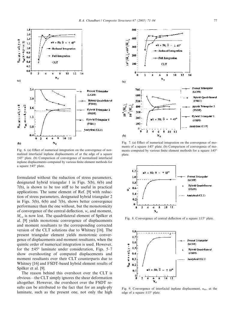
Fig. 6. (a) Effect of numerical integration on the convergence of nor-
malized interfacial inplane displacements of at the edge of a square
±45� plate. (b) Comparison of convergence of normalized interfacial
inplane displacements computed by various finite element methods for
a square ±45� plate.
Fig. 8. Convergence of central deflection of a square ±15� plate.
Fig. 7. (a) Effect of numerical integration on the convergence of mo-
ments of a square ±45� plate. (b) Comparison of convergence of mo-
ments computed by various finite element methods for a square ±45�plate.
Fig. 9. Convergence of interfacial inplane displacement, uint, at the
edge of a square ±15� plate.
R.A. Chaudhuri / Composite Structures 67 (2005) 71–84 77
formulated without the reduction of stress parameters,
designated hybrid triangular 1 in Figs. 5(b), 6(b) and
7(b), is shown to be too stiff to be useful in practical
applications. The same element of Ref. [9] with reduc-
tion of stress parameters, designated hybrid triangular 2in Figs. 5(b), 6(b) and 7(b), shows better convergence
performance than the one without, but the monotonicity
of convergence of the central deflection, wc and moment,
Mx;c is now lost. The quadrilateral element of Spilker et
al. [9] yields monotonic convergence of displacements
and moment resultants to the corresponding corrected
version of the CLT solutions due to Whitney [16]. The
present triangular element yields monotonic conver-gence of displacements and moment resultants, when the
quintic order of numerical integration is used. However,
for the ±45� laminate under consideration, Figs. 5–7
show overshooting of computed displacements and
moment resultants over their CLT counterparts due to
Whitney [16] and FSDT-based hybrid element results of
Spilker et al. [9].
The reason behind this overshoot over the CLT isobvious––the CLT simply ignores the shear deformation
altogether. However, the overshoot over the FSDT re-
sults can be attributed to the fact that for an angle-ply
laminate, such as the present one, not only the high
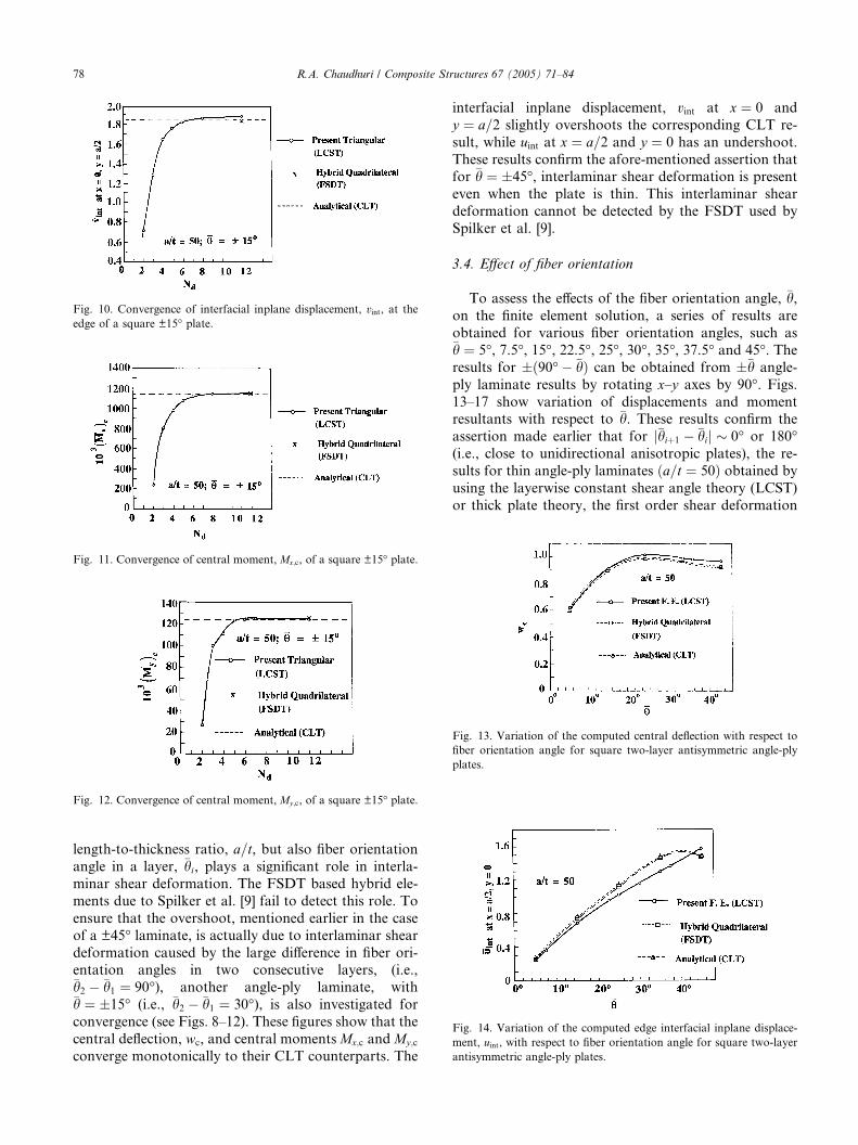
Fig. 11. Convergence of central moment, Mx;c, of a square ±15� plate.
Fig. 10. Convergence of interfacial inplane displacement, vint, at theedge of a square ±15� plate.
Fig. 12. Convergence of central moment, My;c, of a square ±15� plate.
Fig. 13. Variation of the computed central deflection with respect to
fiber orientation angle for square two-layer antisymmetric angle-ply
plates.
Fig. 14. Variation of the computed edge interfacial inplane displace-
ment, uint, with respect to fiber orientation angle for square two-layer
antisymmetric angle-ply plates.
78 R.A. Chaudhuri / Composite Structures 67 (2005) 71–84
length-to-thickness ratio, a=t, but also fiber orientation
angle in a layer, �hi, plays a significant role in interla-
minar shear deformation. The FSDT based hybrid ele-
ments due to Spilker et al. [9] fail to detect this role. To
ensure that the overshoot, mentioned earlier in the case
of a ±45� laminate, is actually due to interlaminar shear
deformation caused by the large difference in fiber ori-entation angles in two consecutive layers, (i.e.,�h2 � �h1 ¼ 90�), another angle-ply laminate, with�h ¼ �15� (i.e., �h2 � �h1 ¼ 30�), is also investigated for
convergence (see Figs. 8–12). These figures show that the
central deflection, wc, and central moments Mx;c and My;c
converge monotonically to their CLT counterparts. The
interfacial inplane displacement, vint at x ¼ 0 and
y ¼ a=2 slightly overshoots the corresponding CLT re-
sult, while uint at x ¼ a=2 and y ¼ 0 has an undershoot.
These results confirm the afore-mentioned assertion thatfor �h ¼ �45�, interlaminar shear deformation is present
even when the plate is thin. This interlaminar shear
deformation cannot be detected by the FSDT used by
Spilker et al. [9].
3.4. Effect of fiber orientation
To assess the effects of the fiber orientation angle, �h,on the finite element solution, a series of results are
obtained for various fiber orientation angles, such as�h ¼ 5�, 7.5�, 15�, 22.5�, 25�, 30�, 35�, 37.5� and 45�. Theresults for �ð90�� �hÞ can be obtained from ��h angle-
ply laminate results by rotating x–y axes by 90�. Figs.13–17 show variation of displacements and momentresultants with respect to �h. These results confirm the
assertion made earlier that for j�hiþ1 � �hij � 0� or 180�(i.e., close to unidirectional anisotropic plates), the re-
sults for thin angle-ply laminates ða=t ¼ 50Þ obtained by
using the layerwise constant shear angle theory (LCST)
or thick plate theory, the first order shear deformation
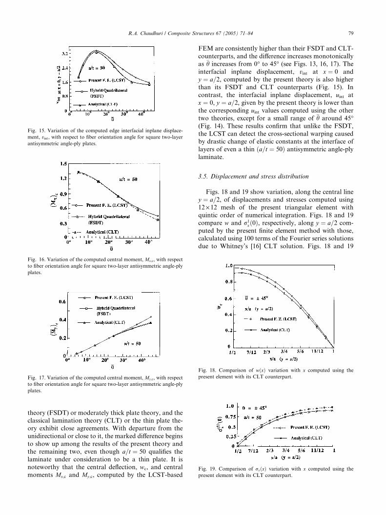
Fig. 15. Variation of the computed edge interfacial inplane displace-
ment, vint, with respect to fiber orientation angle for square two-layer
antisymmetric angle-ply plates.
Fig. 16. Variation of the computed central moment, Mx;c, with respect
to fiber orientation angle for square two-layer antisymmetric angle-ply
plates.
Fig. 17. Variation of the computed central moment, My;c, with respect
to fiber orientation angle for square two-layer antisymmetric angle-ply
plates.
Fig. 18. Comparison of wðxÞ variation with x computed using the
present element with its CLT counterpart.
Fig. 19. Comparison of rxðxÞ variation with x computed using the
present element with its CLT counterpart.
R.A. Chaudhuri / Composite Structures 67 (2005) 71–84 79
theory (FSDT) or moderately thick plate theory, and theclassical lamination theory (CLT) or the thin plate the-
ory exhibit close agreements. With departure from the
unidirectional or close to it, the marked difference begins
to show up among the results of the present theory and
the remaining two, even though a=t ¼ 50 qualifies the
laminate under consideration to be a thin plate. It is
noteworthy that the central deflection, wc, and central
moments Mx;c and My;c, computed by the LCST-based
FEM are consistently higher than their FSDT and CLT-
counterparts, and the difference increases monotonically
as �h increases from 0� to 45� (see Figs. 13, 16, 17). The
interfacial inplane displacement, vint at x ¼ 0 andy ¼ a=2, computed by the present theory is also higher
than its FSDT and CLT counterparts (Fig. 15). In
contrast, the interfacial inplane displacement, uint at
x ¼ 0, y ¼ a=2, given by the present theory is lower than
the corresponding uint values computed using the other
two theories, except for a small range of �h around 45�(Fig. 14). These results confirm that unlike the FSDT,
the LCST can detect the cross-sectional warping causedby drastic change of elastic constants at the interface of
layers of even a thin ða=t ¼ 50Þ antisymmetric angle-ply
laminate.
3.5. Displacement and stress distribution
Figs. 18 and 19 show variation, along the central line
y ¼ a=2, of displacements and stresses computed using
12 · 12 mesh of the present triangular element with
quintic order of numerical integration. Figs. 18 and 19
compare w and r1xð0Þ, respectively, along y ¼ a=2 com-
puted by the present finite element method with those,calculated using 100 terms of the Fourier series solutions
due to Whitney’s [16] CLT solution. Figs. 18 and 19
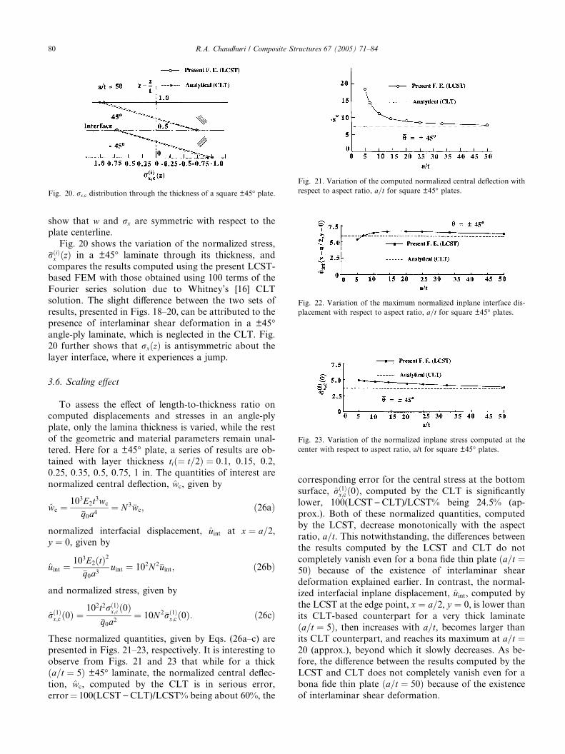
Fig. 20. rx;c distribution through the thickness of a square ±45� plate.Fig. 21. Variation of the computed normalized central deflection with
respect to aspect ratio, a=t for square ±45� plates.
Fig. 22. Variation of the maximum normalized inplane interface dis-
placement with respect to aspect ratio, a=t for square ±45� plates.
Fig. 23. Variation of the normalized inplane stress computed at the
center with respect to aspect ratio, a/t for square ±45� plates.
80 R.A. Chaudhuri / Composite Structures 67 (2005) 71–84
show that w and rx are symmetric with respect to the
plate centerline.
Fig. 20 shows the variation of the normalized stress,�rðiÞx ðzÞ in a ±45� laminate through its thickness, and
compares the results computed using the present LCST-based FEM with those obtained using 100 terms of the
Fourier series solution due to Whitney’s [16] CLT
solution. The slight difference between the two sets of
results, presented in Figs. 18–20, can be attributed to the
presence of interlaminar shear deformation in a ±45�angle-ply laminate, which is neglected in the CLT. Fig.
20 further shows that rxðzÞ is antisymmetric about the
layer interface, where it experiences a jump.
3.6. Scaling effect
To assess the effect of length-to-thickness ratio oncomputed displacements and stresses in an angle-ply
plate, only the lamina thickness is varied, while the rest
of the geometric and material parameters remain unal-
tered. Here for a ±45� plate, a series of results are ob-
tained with layer thickness tið¼ t=2Þ ¼ 0:1, 0.15, 0.2,
0.25, 0.35, 0.5, 0.75, 1 in. The quantities of interest are
normalized central deflection, wc, given by
wc ¼103E2t3wc
�q0a4¼ N 3�wc; ð26aÞ
normalized interfacial displacement, uint at x ¼ a=2,y ¼ 0, given by
uint ¼103E2ðtÞ2
�q0a3uint ¼ 102N 2�uint; ð26bÞ
and normalized stress, given by
rð1Þx;c ð0Þ ¼
102t2rð1Þx;c ð0Þ
�q0a2¼ 10N 2�rð1Þ
x;c ð0Þ: ð26cÞ
These normalized quantities, given by Eqs. (26a–c) are
presented in Figs. 21–23, respectively. It is interesting to
observe from Figs. 21 and 23 that while for a thick
ða=t ¼ 5Þ ±45� laminate, the normalized central deflec-
tion, wc, computed by the CLT is in serious error,
error¼ 100(LCST)CLT)/LCST% being about 60%, the
corresponding error for the central stress at the bottom
surface, rð1Þx;c ð0Þ, computed by the CLT is significantly
lower, 100(LCST)CLT)/LCST% being 24.5% (ap-
prox.). Both of these normalized quantities, computed
by the LCST, decrease monotonically with the aspect
ratio, a=t. This notwithstanding, the differences betweenthe results computed by the LCST and CLT do not
completely vanish even for a bona fide thin plate ða=t ¼50Þ because of the existence of interlaminar shear
deformation explained earlier. In contrast, the normal-
ized interfacial inplane displacement, uint, computed by
the LCST at the edge point, x ¼ a=2, y ¼ 0, is lower than
its CLT-based counterpart for a very thick laminate
ða=t ¼ 5Þ, then increases with a=t, becomes larger than
its CLT counterpart, and reaches its maximum at a=t ¼20 (approx.), beyond which it slowly decreases. As be-fore, the difference between the results computed by the
LCST and CLT does not completely vanish even for a
bona fide thin plate ða=t ¼ 50Þ because of the existence
of interlaminar shear deformation.
Fig. 25. Comparison of the variation of the computed normalized
central deflection with respect to fiber orientation angle for square � �hsymmetric angle-ply plates.
Fig. 26. Comparison of the variation of the computed edge interfacial
inplane displacement, uint, with respect to fiber orientation angle for
square � �h symmetric angle-ply plates.
R.A. Chaudhuri / Composite Structures 67 (2005) 71–84 81
3.7. Example 2: Three-layer unbalanced symmetric angle-
ply plates under uniform pressure
Since convergence and accuracy of the present LCST-based quadratic triangular element have now been
established in the previous example, this section will be
primarily devoted to obtaining certain useful results.
Geometrical configuration, elastic properties, and
thickness of each layer are the same as those of the
balanced antisymmetric angle-ply plate. The only dif-
ference is that the present laminate is comprised of three
layers, stacked symmetrically with respect to the middlesurface, and the fibers are oriented at � �h, �h being po-
sitive, with respect to x-axis. Fig. 24 shows the conver-
gence of CLT-based normalized central deflection of a
thin laminate ða=t ¼ 33:333Þ computed using the
boundary continuous displacement double Fourier ser-
ies solution [18,19] with the number of terms.
In regards to the LCST-based finite element solution,
symmetric lamination permits modeling only the bottomlayer and half of the middle layer, subjected to a uni-
form pressure of �q0 ¼ q0=2. Inplane displacements van-
ish on the middle surface. All four edges are simply
supported. The entire plate planform has been modeled
here to investigate the effect of the fiber orientation
angle, �h, on central deflection, wc, interfacial inplane
displacements, uint at x ¼ �a=2, y ¼ 0, and vint at x ¼ 0,
y ¼ �a=2. These are shown in Figs. 25–27. It is inter-esting to compare these results with their balanced
antisymmetric angle-ply counterparts shown in Figs. 13–
15. The central deflection, wc, here, like the its coun-
terpart in example 1, first increases with �h, and then
decreases until �h ¼ 45� is reached. Variation of uint andvint with �h differs from the corresponding variation of the
previous example. Figs. 25–27 further show that differ-
ence between the displacements computed by the LCSTand CLT increase with the fiber orientation angle, �h, inthe range of �h considered. This can be attributed to the
increase of interlaminar shear deformation or cross-
Fig. 24. Convergence of normalized central deflection computed using
double Fourier series solution for square � �h symmetric angle-ply
plates.
Fig. 27. Comparison of the variation of the computed edge interfacial
inplane displacement, vint, with respect to fiber orientation angle for
square � �h angle-ply plates.
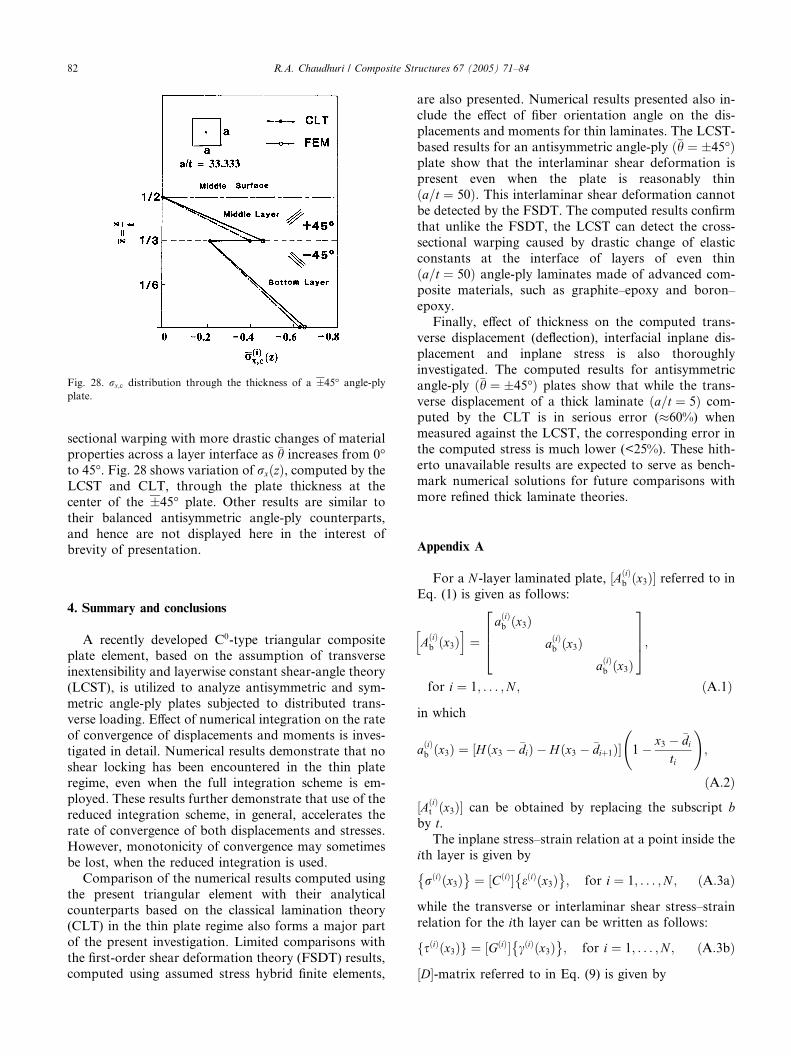
Fig. 28. rx;c distribution through the thickness of a �45� angle-ply
plate.
82 R.A. Chaudhuri / Composite Structures 67 (2005) 71–84
sectional warping with more drastic changes of materialproperties across a layer interface as �h increases from 0�to 45�. Fig. 28 shows variation of rxðzÞ, computed by the
LCST and CLT, through the plate thickness at the
center of the �45� plate. Other results are similar to
their balanced antisymmetric angle-ply counterparts,
and hence are not displayed here in the interest of
brevity of presentation.
4. Summary and conclusions
A recently developed C0-type triangular compositeplate element, based on the assumption of transverse
inextensibility and layerwise constant shear-angle theory
(LCST), is utilized to analyze antisymmetric and sym-
metric angle-ply plates subjected to distributed trans-
verse loading. Effect of numerical integration on the rate
of convergence of displacements and moments is inves-
tigated in detail. Numerical results demonstrate that no
shear locking has been encountered in the thin plateregime, even when the full integration scheme is em-
ployed. These results further demonstrate that use of the
reduced integration scheme, in general, accelerates the
rate of convergence of both displacements and stresses.
However, monotonicity of convergence may sometimes
be lost, when the reduced integration is used.
Comparison of the numerical results computed using
the present triangular element with their analyticalcounterparts based on the classical lamination theory
(CLT) in the thin plate regime also forms a major part
of the present investigation. Limited comparisons with
the first-order shear deformation theory (FSDT) results,
computed using assumed stress hybrid finite elements,
are also presented. Numerical results presented also in-
clude the effect of fiber orientation angle on the dis-
placements and moments for thin laminates. The LCST-
based results for an antisymmetric angle-ply ð�h ¼ �45�Þplate show that the interlaminar shear deformation is
present even when the plate is reasonably thin
ða=t ¼ 50Þ. This interlaminar shear deformation cannot
be detected by the FSDT. The computed results confirm
that unlike the FSDT, the LCST can detect the cross-
sectional warping caused by drastic change of elastic
constants at the interface of layers of even thin
ða=t ¼ 50Þ angle-ply laminates made of advanced com-posite materials, such as graphite–epoxy and boron–
epoxy.
Finally, effect of thickness on the computed trans-
verse displacement (deflection), interfacial inplane dis-
placement and inplane stress is also thoroughly
investigated. The computed results for antisymmetric
angle-ply ð�h ¼ �45�Þ plates show that while the trans-
verse displacement of a thick laminate ða=t ¼ 5Þ com-puted by the CLT is in serious error (�60%) when
measured against the LCST, the corresponding error in
the computed stress is much lower (<25%). These hith-
erto unavailable results are expected to serve as bench-
mark numerical solutions for future comparisons with
more refined thick laminate theories.
Appendix A
For a N -layer laminated plate, ½AðiÞb ðx3Þ� referred to in
Eq. (1) is given as follows:
AðiÞb ðx3Þ
h i¼
aðiÞb ðx3ÞaðiÞb ðx3Þ
aðiÞb ðx3Þ
2664
3775;
for i ¼ 1; . . . ;N ; ðA:1Þ
in which
aðiÞb ðx3Þ ¼ ½Hðx3 � �diÞ � Hðx3 � �diþ1Þ� 1
� x3 � �di
ti
!;
ðA:2Þ
½AðiÞt ðx3Þ� can be obtained by replacing the subscript b
by t.The inplane stress–strain relation at a point inside the
ith layer is given by
rðiÞðx3Þ� �
¼ ½CðiÞ� eðiÞðx3Þ� �
; for i ¼ 1; . . . ;N ; ðA:3aÞ
while the transverse or interlaminar shear stress–strain
relation for the ith layer can be written as follows:
fsðiÞðx3Þg ¼ ½GðiÞ� cðiÞðx3Þ� �
; for i ¼ 1; . . . ;N ; ðA:3bÞ
½D�-matrix referred to in Eq. (9) is given by

R.A. Chaudhuri / Composite Structures 67 (2005) 71–84 83
½D� ¼ ½DB� ½0�½0� ½DS�
� �; ðA:4Þ
in which
½DB� ¼
Dð1Þb
h iDð1Þ
t
h iDð1Þ
bt
h iDð1Þ
t
h iþ Dð2Þ
b
h iDð2Þ
bt
h iDði�1Þ
bt
h iDði�1Þ
t
h iþ ½DðiÞ
b � DðiÞbt
h iDðN�1Þ
bt
h iDðN�1Þ
t
h iþ DðNÞ
b
h iDðNÞ
bt
h iDðNÞ
bt
h iDðNÞ
t
h i
26666666664
37777777775;
ðA:5aÞ
and
½DS� ¼½Dð1Þ
s �½DðiÞ
s �½DðNÞ
s �
24
35; ðA:5bÞ
while the sub-matrices are defined as shown below:
½DðiÞb � ¼ ½DðiÞ
t � ¼ 2½DðiÞbt � ¼
ti3½CðiÞ�;
for i ¼ 1; . . . ;N ; ðA:6aÞ
½DðiÞs � ¼ ti½GðiÞ�; for i ¼ 1; . . . ;N ; ðA:6bÞ
½Bj�-matrix referred to in Eq. (16) is given by
½Bj� ¼
½R� ½0�½R� ½0�
½R� ½0�½M ð1Þ� ½N ð1Þ� ½T �
½M ðiÞ� ½N ðiÞ� ½T �½M ðNÞ� ½N ðNÞ� ½T �
26666664
37777775; ðA:7Þ
whose submatrices are given as follows:
½R� ¼ ½½R1� � � � ½Rk� � � � ½R6��; k ¼ 1; . . . 6; ðA:8aÞwith
½Rk� ¼/k;1 0
0 /k;2
/k;2 /k;1
24
35; ðA:8bÞ
½T � ¼ ½½T1� � � � ½Tk� � � � ½T6��; k ¼ 1; . . . ; 6; ðA:9aÞ
½Tk� ¼/k;1
/k;2
� �: ðA:9bÞ
½N ðiÞ� ¼ ½½N ðiÞ1 � � � � ½N ðiÞ
k � � � � ½N ðiÞ6 �; k ¼ 1; . . . ; 6;
i ¼ 1; . . . ;N ; ðA:10aÞ
with
½N ðiÞk � ¼
/kti
/kti
" #; ðA:10bÞ
while
½M ðiÞ� ¼ �½N ðiÞ�; i ¼ 1; . . . ;N : ðA:11Þ
References
[1] Basset AB. On the extension and flexure of cylindrical and
spherical thin elastic shells. Phil Trans Roy Soc Lond Ser A
1890;181:433–80.
[2] Nelson RB, Lorch DR. A refined theory for laminated orthotro-
pic plates. ASME J Appl Mech 1974;41:177–83.
[3] Levinson M. An accurate simple theory of the statics and
dynamics of elastic plates. Mech Res Commun 1980;7:343–50.
[4] Chaudhuri RA, Kabir HRH. Fourier solution to higher-order
theory based laminated shell boundary-value problem. AIAA J
1995;33:1681–8.
[5] Noor AK, Burton WS. Assessment of shear deformation theories
for multilayered composite plates. Appl Mech Rev 1989;42:1–12.
[6] Pagano NJ. Exact solution for rectangular bidirectional compos-
ites and sandwich plates. J Compos Mater 1970;4:931–3.
[7] Srinivas S, Rao AK. Bending, vibration and buckling of simply
supported thick orthotropic rectangular plates and laminates. Int
J Solids Struct 1970;6:1463–81.
[8] Mau ST, Tong P, Pian THH. Finite element solution for
laminated thick plates. J Compos Mater 1977;11:51–70.
[9] Spilker RL, Chou SC, Orringer O. Alternate hybrid-stress
elements for analysis of multi-layer composite plates. J Compos
Mater 1977;11:51–70.
[10] Seide P. An improved approximate theory for the bending of
laminated plates. In: Nemat-Nasser S, editor. Mechanics today,
vol. 5. NY: Pergamon Press; 1980. p. 451–65.
[11] Spilker RL, Orringer O, Witmer EA, Verbiese S, French S, Harris
A. Use of hybrid-stress finite-element model for the static and
dynamic analysis of multi-layer composite plates and shells.
Report, AMMRC CTR 76-29, ASRL TR 181-2, ASRL, MIT,
Cambridge, MA, September 1976.
[12] Chaudhuri RA, Seide P. Triangular finite element for analysis of
thick laminated plates. Int J Num Meth Engng 1987;24:1203–
24.
[13] Seide P, Chaudhuri RA. Triangular finite element for analysis of
thick laminated shells. Int J Num Meth Engng 1987;24:1563–79.
[14] Chaudhuri RA. A simple and efficient plate bending element.
Comput Struct 1987;25:817–24.

84 R.A. Chaudhuri / Composite Structures 67 (2005) 71–84
[15] Zienkiewicz OC. The finite element method. 3rd ed. London:
McGraw-Hill; 1977.
[16] Whitney JM. Bending–extensional coupling in laminated plates
under transverse loading. J Compos Mater 1969;3:261–6.
[17] Strang G, Fix GJ. An analysis of the finite element method.
Englewood Cliffs, NJ: Prentice-Hall; 1973.
[18] Green AE, Hearmon RF. The buckling of flat rectangular plates.
Phil Mag 1954;36:659–87.
[19] Chaudhuri RA, Balaraman K, Kunukkasseril VX. A combined
theoretical and experimental investigation on free vibration of
thin symmetrically laminated anisotropic plates. Compos Struct,
in press.