
ANALYSIS OF ELECTROMAGNETIC FIELD … In Electromagnetics Research B, Vol. 51, 291{306, 2013...
16
Progress In Electromagnetics Research B, Vol. 51, 291–306, 2013 ANALYSIS OF ELECTROMAGNETIC FIELD COUPLING TO MICROSTRIP LINE CONNECTED WITH NONLIN- EAR COMPONENTS Hui Yan 1 , Liping Yan 1, * , Xiang Zhao 1 , Haijing Zhou 2 , and Kama Huang 1 1 School of Electronics and Information Engineering, Sichuan Univer- sity, Chengdu 610064, China 2 Institute of Applied Physics and Computation Mathematics, Beijing 100088, China Abstract—An analysis method for electromagnetic field coupling to microstrip line connected with nonlinear components is proposed in this paper. Different from the published work, not only the voltage and current response of the nonlinear component connected to the transmission line (TL) can be obtained, but also the power transmitted from this nonlinear component to the next one at both the fundamental frequency and harmonics can be predicted. The proposed method suitably combines the classical field-to-TL coupling theory and the nonlinear large-signal scattering parameters on the basis of a black box model in frequency-domain. Then this method is experimentally validated by a laboratory system including a microstrip line connected with a simple nonlinear component constituted by the anti-paralleled HSMS-282C Schottky diodes pair welded to a 50 Ω microstrip line. The calculated results using the proposed method show good agreement with the measured data. 1. INTRODUCTION The electromagnetic environmental effects attract increasing interests of researchers and engineers as more and more wireless communication systems have been developed and applied widely. In recent years, researchers begin to pay increasing attentions to electromagnetic compatibility analysis on system level [1, 2]. The electromagnetic compatibility modeling inside an electronic system involves several Received 20 March 2013, Accepted 25 April 2013, Scheduled 29 April 2013 * Corresponding author: Liping Yan ([email protected]).
Transcript of ANALYSIS OF ELECTROMAGNETIC FIELD … In Electromagnetics Research B, Vol. 51, 291{306, 2013...

Progress In Electromagnetics Research B, Vol. 51, 291–306, 2013
ANALYSIS OF ELECTROMAGNETIC FIELD COUPLINGTO MICROSTRIP LINE CONNECTED WITH NONLIN-EAR COMPONENTS
Hui Yan1, Liping Yan1, *, Xiang Zhao1, Haijing Zhou2, andKama Huang1
1School of Electronics and Information Engineering, Sichuan Univer-sity, Chengdu 610064, China2Institute of Applied Physics and Computation Mathematics,Beijing 100088, China
Abstract—An analysis method for electromagnetic field coupling tomicrostrip line connected with nonlinear components is proposed inthis paper. Different from the published work, not only the voltageand current response of the nonlinear component connected to thetransmission line (TL) can be obtained, but also the power transmittedfrom this nonlinear component to the next one at both the fundamentalfrequency and harmonics can be predicted. The proposed methodsuitably combines the classical field-to-TL coupling theory and thenonlinear large-signal scattering parameters on the basis of a blackbox model in frequency-domain. Then this method is experimentallyvalidated by a laboratory system including a microstrip line connectedwith a simple nonlinear component constituted by the anti-paralleledHSMS-282C Schottky diodes pair welded to a 50 Ω microstrip line. Thecalculated results using the proposed method show good agreementwith the measured data.
1. INTRODUCTION
The electromagnetic environmental effects attract increasing interestsof researchers and engineers as more and more wireless communicationsystems have been developed and applied widely. In recent years,researchers begin to pay increasing attentions to electromagneticcompatibility analysis on system level [1, 2]. The electromagneticcompatibility modeling inside an electronic system involves several
Received 20 March 2013, Accepted 25 April 2013, Scheduled 29 April 2013* Corresponding author: Liping Yan ([email protected]).

292 Yan et al.
big problems, such as aperture coupling, field-to-transmission line(TL) coupling, nonlinear components modeling which is necessary forcircuit simulation. External electromagnetic wave can penetrate intothe system through apertures or slots, and then induce current onTLs. This induced current may flow along the wires and elementsin the system and cause interference. Though we can use powerfulcommercial software like ADS and HSPICE to simulate circuits andcalculate the voltage or current on each element, it is hard to set up theelectromagnetic compatibility model of the whole system illuminatedby electromagnetic waves. One of the challenges is the evaluationof electromagnetic field coupling to TL connected with a nonlinearcomponent and the prediction of the transmitted power from thisnonlinear component towards the next element/device.
Classical field-to-TL coupling theory has been developed andfrequently used to compute the coupling of electromagnetic fieldsto TLs with linear terminations [3–14]. Especially, the radiatedinterference on printed circuit board (PCB) layout through the field-to-TL route has become a growing concern in prediction of systemreliability [15, 16]. However, nonlinear electronic components ordevices are essential parts of electronic systems. It is hard to analyzethe electromagnetic field coupling to TLs connected with nonlinearloads since the response of the nonlinear loads is more complicatedthan of linear ones. Several approaches have been developed to tryto solve this problem. Tesche provided an example to illustratethe application of transient BLT equation, which is first proposedin 1999 [17], to the external electromagnetic field coupling to a TLwith nonlinear termination [18, 19]. However, it is not convenient touse for nonlinear loads where a nonlinear matrix equation should besolved first to determine the reflection coefficients in time domain [20].The effects of nonlinear termination on the multi-transmission line intime-domain are also investigated using finite-difference time-domain(FDTD) method for dynamic nonlinear elements [21]. As we allknow, large computational consumption is needed to solve such aproblem using full wave analysis. Xie proposed a hybrid FDTD-SPICEmethod [22] to analyze lossless TLs with nonlinear or time-varyingloads illuminated by a non-uniform electromagnetic, in which effectivevoltage and current sources are obtained first using field-to-TL couplingmethod after the incident fields to the lines are calculated using FDTD,and then imported into SPICE to deal with the nonlinear loads [23].Bayram mentioned nonlinear loads in the hybrid S-parameters methodused for field-to-TL coupling [24], but again the nonlinear loads hadto be handled by HSPICE or ADS.
In these methods mentioned above, nonlinear components are

Progress In Electromagnetics Research B, Vol. 51, 2013 293
handled as the terminal loads of the TL, namely, a one-port network.However, in the real electronic system, nonlinear components or devicessometimes connect with other components or TLs, working as two-port or multi-port networks. How to model such a system andget the output power from the nonlinear components is still a bigchallenge. It is often too complex to permit complete EMC simulationat the device level of description. A complete system simulation canbecome practical, however, provided that the models of the nonlinearblocks or ICs are given [25]. Therefore, a more applicable model,which can be combined conveniently with field-to-TL coupling theoryand S-parameters of linear components, is necessary for nonlinearcomponents. Though the nonlinear large-signal scattering parametersbased on the black box model in frequency-domain [26] can be used tomodel nonlinear networks, much efforts are necessary to combine thismodel with field-to-TL coupling theory properly.
The goal of this paper is to develop an analysis method forelectromagnetic field coupling to microstrip line connected withnonlinear components and then obtain the output power from thisnonlinear component towards the next element. The proposed methodbuilds upon the classical field-to-TL coupling theory and nonlinearlarge-signal scattering parameters, and skills for combination of thesetwo models are considered. In the following, the complete analysismethod is presented in Section 2. The predicted results from theproposed method and experimental validation are provided in detailin Section 3 and we summarize our work briefly in Section 4.
2. MODELS AND BASIC PRINCIPLES
The classical field-to-TL coupling model is usually applied to calculatethe voltage and current induced along the line or on linear loads. Ifa nonlinear component is connected to the line not as a termination,as a result, the output from the nonlinear component will influencethe response of the next component. In order to analyze such a case,the nonlinear large-signal scattering parameters based on the blackbox model in frequency-domain are used to describe the nonlinearcomponent or devices. With this model, whatever the nonlinearcomponent, device and even subsystem are, all can be describedconcisely by a scattering parameters matrix [27].
2.1. Field-to-transmission Line Coupling Theory
Microstrip lines are taken into consideration here due to their popularapplications in microwave system. Fig. 1 shows such a line illuminated

294 Yan et al.
l
θ
iE iH
φ
ik
O
h
w
x
z
Figure 1. Microstrip structure illuminated by electromagnetic wave.
by a time-harmonic electromagnetic wave with frequency ω.Three models proposed by Taylor, Agrawal and Rachidi
respectively all can be used to describe the field interaction with TLs,and the total induced voltage waveforms obtained using them areidentical [28–30]. The Taylor model is used here, because the totalcurrent and voltage induced on the line are expected in order to getthe response of the linear/nonlinear component connected with theline. The external field results in a forcing function expressed in termsof the exciting magnetic and electric flux. This forcing function (sourceterms) are included as a set of distributed series voltage and parallelcurrent sources along the line. Consequently, the TL equations aredescribed as (1a) and (1b).
dV (y)dy
+ jωLI(y) = vs(y) (1a)
dI(y)dy
+ jωCV (y) = is(y) (1b)
where the distributed voltage and current source excitation terms vs
and is for the microstrip line structure can be written as (2a) and (2b),and the per-unit-length inductance L and capacitance C are definedas (3a) and (3b) [31].
vs(y) = jωµ0
∫ h
0Hp
x(0, y, z)dz (2a)
is(y) = −jωC
∫ h
0Ep
z (0, y, z)dz + jωε1
∫ w/2
−w/2Ep
z (x, y, h)dx (2b)
L =− ∫ h
0 µ0Hs(0, y, z) · xdz∫ +w/2−w/2 Js(x, y) · ydx
(3a)
C =
∫ + w/2−w/2 ε1Es(x, y, h) · zdx
∫ h0 Es(0, y, z) · zdz
(3b)

Progress In Electromagnetics Research B, Vol. 51, 2013 295
where the “primary” fields (Ep, Hp) are defined as the field excited bythe incident electromagnetic wave in the presence of the ground planeand the dielectric substrate and in the absence of the metal strip. The“secondary” fields (Es, Hs) are the field scattered by the microstripconductor when excited by the “primary” field and in the presence ofthe ground plane and the dielectric substrate.
Note that the TL approximation (or the quasi-TEM assumption)is used in these filed-to-TL coupling models. This approximation ismainly limited by the condition that the transverse dimensions ofthe line and its return path (essentially the line height) should bemuch smaller than the minimum significant wavelength of the excitingelectromagnetic field λmin, which corresponds to a cutoff frequency.Beyond that, higher modes may be excited and the classical modelsare not suitable for such a problem. As a result, the high-frequencyfield-to-TL coupling theory should be used [28]. This, however, isbeyond the scope of this paper.
2.2. Nonlinear Components Modeling
The nonlinear large-signal scattering parameters, which are based onthe black box model in frequency-domain, are used to describe thecharacteristics of nonlinear devices or circuits [26]. Nonlinear large-signal S-parameters can be defined as ratios of the reflected andincident wave variables of each port [32], including the fundamentaland harmonic components of the input and output signals since energycan be transferred to other frequencies in a nonlinear device. Note thatthe nonlinear S-parameters can be used to describe any nonlinear N -port network. If harmonic components up to mth order are taken intoconsideration, the nonlinear S-parameters will be a (N ×m)2 matrix.In this paper, for the nonlinear component used in the followingexperiments, the power of harmonics greater than 3rd are much lessthan that of the third harmonic and can be neglected. Therefore, atwo-port network with harmonics up to 3rd, as shown in Fig. 2, is
Nonlinear
Network
a1j
b1k
b2k
a2j
ω1 ω2 ωm... ... ω1 ω2 ωm
... ...
ω1 ω2 ωm... ... ω1 ω2 ωm
... ...
Figure 2. Diagram of a nonlinear two-port network.

296 Yan et al.
considered as an example.In Fig. 2, aj
m and bkn represent the incident and reflected travelling
waves, where the subscripts m and n denote the port numberand superscripts j and k denote the spectral component number,respectively. Based on the S-parameters defined for a linear network,let if only the fundamental, second and third harmonic componentsare taken into account, nonlinear S-matrix is given in the followingequation,
S11 11
S S S S S12 13 11 12 1312 12 1211 11
S S S S S S21 22 23 21 22 2311 12 12 1211 11
S S S S S S11 12 12 1211 11 31 32 33 31 32 33
S11
S S S S S12 13 11 12 13
S S S S S S21 22 23 21 22 23
S S S S S S31 32 33 31 32 33
21 21 21
21 21 21
21 21 21
22 22 22
22 22 22
22 22 22
a1
b
1
b
b
b
b
b
1
1
2
3
2
2
2
1
2
3
11
1
1
2
3
2
2
2
1
2
3
a
a
a
a
a
= = (4)
where each element Skjnm in [S] can be defined as
Skjnm =
bkn
ajm
ay
x = 0 for x 6= m
ayx = 0 for all x = m & all y 6= j
(5)
Figure 3 shows a flow chart to illustrate the mechanism of theproposed method in detail. First the induced voltage and currentalong the line are calculated using the field-to-TL coupling theory.If a nonlinear component is connected to the line, the equivalentimpedance Zeff should be obtained in advance in order to solve theTL equations, because it varies in terms of the power input to thenonlinear component. As a result, the induced voltage and currentalong the line change accordingly. That will be discussed in detaillater.
Based on the induced voltage and equivalent impedance, thepower of the incident wave to the nonlinear component is achieved.Then the nonlinear S-parameters of the nonlinear components areextracted by experiments. Based on these S-parameters and powerof the incident wave, the output power from the nonlinear componentcan be predicted. Note that the nonlinear S-parameters based onthe black-box model can describe any nonlinear elements or devices.Consequently, the proposed method has a good applicability as longas the necessary S-parameters of nonlinear components/devices areknown. An example for extraction of nonlinear S-parameters usingexperiments is described in the following.

Progress In Electromagnetics Research B, Vol. 51, 2013 297
Equivalent Impedance
of Nonlinear Component
Z eff
iH
Field-to-Transmission Line Extraction of Nonlinear Large-Signal Scattering
Parameters [S]
Nonlinear
ComponentP
out
Microstrip line
Output Power from
Nonlinear ComponentPout
Einc, Hinc
h
w
iE
ik
l
xφ
θo
Coupling Theory
S11 11 S S S S S12 13 11 12 13
12 12 1211 11 ...
S S S S S S ... 21 22 23 21 22 2311 12 12 1211 11
S S S S S S ... 11 12 12 1211 11 31 32 33 31 32 33
S11
S S S S S12 13 11 12 13 ...
S S S S S S ... 21 22 23 21 22 23
S S S S S S ... 31 32 33 31 32 33
21 21 21
21 21 21
21 21 21
22 22 22
22 22 22
22 22 22 ... ... ... ... ... ... b]=[S][a][
Figure 3. The flow chart of the proposed method.
2.3. Extraction of Nonlinear Large-signal ScatteringParameters
In this part, an example is presented to show how to extract thenonlinear S-parameters. Fig. 4 provides a simple nonlinear component
w =2.74 mm
h=
1m
m
(a) (b)
l =40 mm
Figure 4. The nonlinear component under test, (a) top view and(b) side view.
298 Yan et al.
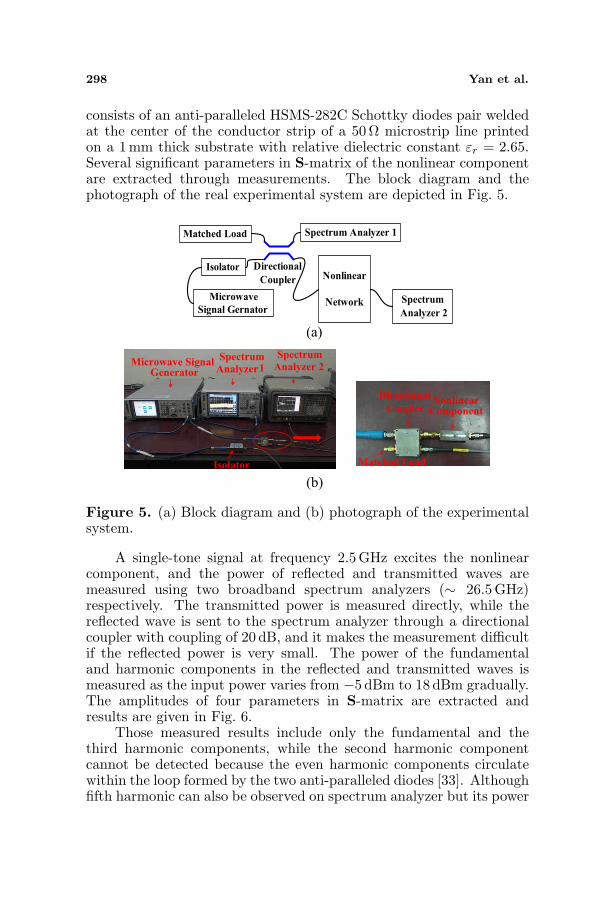
consists of an anti-paralleled HSMS-282C Schottky diodes pair weldedat the center of the conductor strip of a 50 Ω microstrip line printedon a 1 mm thick substrate with relative dielectric constant εr = 2.65.Several significant parameters in S-matrix of the nonlinear componentare extracted through measurements. The block diagram and thephotograph of the real experimental system are depicted in Fig. 5.
Spectrum
Analyzer 2
Nonlinear
Network
Spectrum Analyzer 1Matched Load
Directional
Coupler
Microwave
Signal Gernator
Isolator
Isolator
Microwave Signal Generator
Spectrum
Analyzer1
Spectrum
Analyzer 2
NonlinearComponent
Directional
Coupler
Matched Load
(a)
(b)
Figure 5. (a) Block diagram and (b) photograph of the experimentalsystem.
A single-tone signal at frequency 2.5 GHz excites the nonlinearcomponent, and the power of reflected and transmitted waves aremeasured using two broadband spectrum analyzers (∼ 26.5GHz)respectively. The transmitted power is measured directly, while thereflected wave is sent to the spectrum analyzer through a directionalcoupler with coupling of 20 dB, and it makes the measurement difficultif the reflected power is very small. The power of the fundamentaland harmonic components in the reflected and transmitted waves ismeasured as the input power varies from −5 dBm to 18 dBm gradually.The amplitudes of four parameters in S-matrix are extracted andresults are given in Fig. 6.
Those measured results include only the fundamental and thethird harmonic components, while the second harmonic componentcannot be detected because the even harmonic components circulatewithin the loop formed by the two anti-paralleled diodes [33]. Althoughfifth harmonic can also be observed on spectrum analyzer but its power

Progress In Electromagnetics Research B, Vol. 51, 2013 299
(a) (b)
Figure 6. Measured nonlinear S-parameters: (a) the fundamentaland (b) the third harmonic components.
is far less than the third harmonic. The reflection and transmission ofboth the fundamental and third harmonic components vary nonlinearlyin terms of the input power in Fig. 6. Especially, the power of thefundamental component is much larger than that of the third harmonicones. For further inspection of Fig. 6, the transmitted power is largerthan the reflected one for the fundamental component, but just theopposite for the third harmonic. Here the reflected power of thethird harmonic component can be detected only when the input poweris greater than 7 dBm, because the reflected wave is attenuated by20 dB due to the directional coupler before measured using spectrumanalyzer.
Using the field-to-TL coupling model mentioned previously, thevoltage and current induced along the microstrip line can be obtainedand then the power transmitted to the component connected withthe line can be calculated. Combined with the nonlinear large-signalS-parameters, we can predict the output power of fundamental andharmonic components from the nonlinear component towards the nextelement.
3. RESULTS AND ANALYSIS
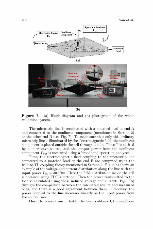
The validation of the results obtained from the proposed analysismethod is supported by experimental data measured on a laboratorysystem, as shown in Fig. 7. A TEM cell is used to generate a relativelyuniform electromagnetic field, and a 40 mm long 50Ω microstrip lineprinted on a 1mm thick substrate with relative dielectric constant ofεr = 2.65 is placed vertically inside the cell. Correspondingly, theincident angle θ in Fig. 1 is 0, and the angle between the incidentplane and XOZ plane φ is 90.
300 Yan et al.
Nonlinear
Component
Spectrum Analyzer
Pout
Microwave Source
Pin
MatchedLoad
Isolatorxz
y
iH
iEik
(a)
(b)
B
A
Figure 7. (a) Block diagram and (b) photograph of the wholevalidation system.
The microstrip line is terminated with a matched load at end Aand connected to the nonlinear component (mentioned in Section 2)at the other end B (see Fig. 7). To make sure that only this ordinarymicrostrip line is illuminated by the electromagnetic field, the nonlinearcomponent is placed outside the cell through a hole. The cell is excitedby a microwave source, and the output power from the nonlinearcomponent Pout is measured using a broadband spectrum analyzer.
First, the electromagnetic field coupling to the microstrip lineconnected to a matched load at the end B are computed using thefield-to-TL coupling theory mentioned in Section 2. Fig. 8(a) shows anexample of the voltage and current distribution along the line with theinput power Pin = 30dBm. Here the field distribution inside the cellis obtained using FDTD method. Then the power transmitted to theload is calculated using these induced voltage and current. Fig. 8(b)displays the comparison between the calculated results and measuredones, and there is a good agreement between them. Obviously, thepower coupled to the line increases linearly as the input power fromthe source rises.
Once the power transmitted to the load is obtained, the nonlinear

Progress In Electromagnetics Research B, Vol. 51, 2013 301
(a) (b)
Figure 8. Calculated results using field-to-TL coupling theory.(a) Magnitude of induced voltage and current along the line, and(b) power transmitted to the matched load.
S-parameters are used to get both fundamental and third harmonicoutput power Pout from the nonlinear component according to Eq. (4).Because the nonlinear component is connected to the broadbandspectrum analyzer (namely, a matched load), there is no incident powerat port 2© at all. Consequently, Eq. (4) is simplified as the followingEq. (6), by which the reflected power at the port 1© and transmittedpower at the port 2© can then be calculated.
S11 11
S S S S S12 13 11 12 1312 12 1211 11
S S S S S S21 22 23 21 22 2311 12 12 1211 11
S S S S S S11 12 12 1211 11 31 32 33 31 32 33
S11
S S S S S12 13 11 12 13
S S S S S S21 22 23 21 22 23
S S S S S S31 32 33 31 32 33
21 21 21
21 21 21
21 21 21
22 22 22
22 22 22
22 22 22
a1
b
1
b
b
b
b
b
1
1
2
3
2
2
2
1
2
3
11
= = (6)
0
0
0
0
0
The necessary four parameters in the dashed box have alreadybeen extracted through measurements and the rest two |S21
11 | and |S2121 |
are zero, since there is no second harmonic response at both ports, asmentioned in Section 2.
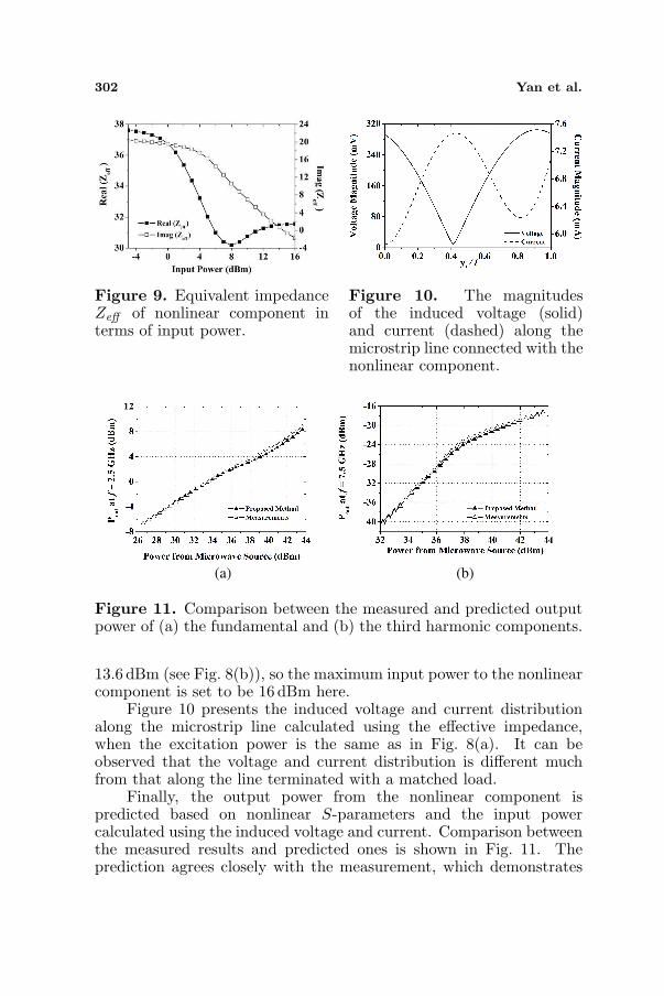
A question deserving more attention is that the induced voltageand current distribution highly depend on the incident electromagneticwave and the loads at both ends of the TL. However, the equivalentimpedance of the nonlinear component usually varies in terms of thepower input to it, which results in the power transmitted to it changingaccordingly. Therefore, the equivalent impedance Zeff of the nonlinearcomponent in terms of the input power is simulated using ADS, andresults are shown in Fig. 9. The maximum transmitted power tomatched load due to the induced voltage and current on the line is
302 Yan et al.
Figure 9. Equivalent impedanceZeff of nonlinear component interms of input power.
Figure 10. The magnitudesof the induced voltage (solid)and current (dashed) along themicrostrip line connected with thenonlinear component.
(b)(a)
Figure 11. Comparison between the measured and predicted outputpower of (a) the fundamental and (b) the third harmonic components.
13.6 dBm (see Fig. 8(b)), so the maximum input power to the nonlinearcomponent is set to be 16 dBm here.
Figure 10 presents the induced voltage and current distributionalong the microstrip line calculated using the effective impedance,when the excitation power is the same as in Fig. 8(a). It can beobserved that the voltage and current distribution is different muchfrom that along the line terminated with a matched load.
Finally, the output power from the nonlinear component ispredicted based on nonlinear S-parameters and the input powercalculated using the induced voltage and current. Comparison betweenthe measured results and predicted ones is shown in Fig. 11. Theprediction agrees closely with the measurement, which demonstrates
Progress In Electromagnetics Research B, Vol. 51, 2013 303
the validation of the proposed method. Furthermore, the output powerof both fundamental and third harmonic components varies nonlinearlyas the input power from the microwave source rises.
It is noteworthy that electromagnetic wave is reflected from thenonlinear component back to the ordinary microstrip line, not onlyat the fundamental frequency, but also at the third harmonic. Asmentioned previously, the ordinary microstrip line is terminated with amatched load at port A, and therefore the power of the reflected waveis absorbed. However, this reflected wave (especially the harmoniccomponent) may cause other problems in a real electronic system.
4. CONCLUSIONS
An analysis method for electromagnetic field coupling to microstripline connected with nonlinear components is proposed in this paper.The classical field-to-TL coupling theory (Taylor model) is used toget the response of a microstrip line illuminated by electromagneticwave, while nonlinear components or devices are modeled by large-signal scattering parameters which are based on the black box modelin frequency-domain. Then the electromagnetic field coupling tomicrostrip line connected with nonlinear components is analyzed bycombining these two models together properly and considering theequivalent impedance of the nonlinear component. The predictedresults using the proposed method are in good agreements withmeasured ones. Although the nonlinear component used in this paperis not a practical circuit like a mixer or low noise amplifier (LNA), theproposed method is appropriate for all the nonlinear devices or ICs,due to its basis on the black box model.
ACKNOWLEDGMENT
This work is supported by NSAF (Grant No. 11176017) and 973Program (Grant No. 2013CB328904). The authors would like to thankthe reviewers for their helpful comments in the preparation of thepaper.
REFERENCES
1. Wu, Q., J.-H. Fu, and F.-Y. Meng, “A system-level EMC tech-nical support platform for network-based computers,” 2008 Asia-Pacific Symposium on Electromagnetic Compatibility & 19th In-ternational Zurich Symposium on Electromagnetic Compatibility,642–645, May 19–22, 2008.

304 Yan et al.
2. Zamir, R., V. Bar-Natan, and E. Recht, “System level EMC— From theory to practice,” International Symposium onElectromagnetic Compatibility, Vol. 3, 741–743, 2005.
3. Taylor, C. D., R. S. Satterwhite, and C. W. Harrison, Jr.,“The response of a terminated two-wire transmission line excitedby a nonuniform electromagnetic field,” IEEE Transactions onAntennas and Propagation, Vol. 13, No. 6, 987–989, 1965.
4. Agrawal, A. K., H. J. Price, and S. H. Gurbaxani, “Transientresponse of multi-conductor transmission lines excited bya nonuniform electromagnetic field,” IEEE Transactions onElectromagnetic Compatibility, Vol. 22, No. 2, 119–129, 1980.
5. Rachidi, F., “Formulation of the field-to-transmission linecoupling equations in terms of magnetic excitation field,” IEEETransactions on Electromagnetic Compatibility, Vol. 35, No. 3,404–407, 1993.
6. Rajkumar, E. R., B. Ravelo, M. Bensetti, and P. Fernandez-Lopez, “Application of a hybrid model for the susceptibility ofarbitrary shape metallic wires disturbed by EM near-field radiatedby electronic structures,” Progress In Electromagnetics ResearchB, Vol. 37, 143–169, 2012.
7. Xie, Y.-Z., J. Guo, and F. G. Canavero, “Analytic iterativesolution of electromagnetic pulse coupling to multiconductortransmission lines,” IEEE Transactions on ElectromagneticCompatibility, Vol. PP, No. 99, 1–16, 2013.
8. Xie, H., J. Wang, R. Fan, and Y. Liu, “SPICE models for radiatedand conducted susceptibility analyses of multiconductor shieldedcables,” Progress In Electromagnetics Research, Vol. 103, 241–257,2010.
9. Xie, H., J. Wang, R. Fan, and Y. Liu, “Study of losseffect of transmission lines and validity of a SPICE modelin electromagnetic topology,” Progress In ElectromagneticsResearch, Vol. 90, 89–103, 2009.
10. Zou, J., T. B. Jin, W. W. Li, J. Lee, and S. Chang, “A Hermiteinterpolation model to accelerate the calculation of the horizontalelectric field of a lightning channel along a transmission line,”IEEE Transactions on Electromagnetic Compatibility, Vol. 55,No. 1, 124–131, 2013.
11. Manfredi, P. and F. G. Canavero, “Polynomial chaos for randomfield coupling to transmission lines,” IEEE Transactions onElectromagnetic Compatibility, Vol. 54, No. 3, 677–680, 2012.
12. Poljak, D. and K. El Khamlichi Drissi, “Electromagnetic fieldcoupling to over head wire configurations: Antenna model versus
Progress In Electromagnetics Research B, Vol. 51, 2013 305
transmission line approach,” International Journal of Antennasand Propagation, Vol. 2012.
13. Magdowski, M. and R. Vick, “Closed-form formulas for thestochastic electromagnetic field coupling to a transmission linewith arbitrary loads,” IEEE Transactions on ElectromagneticCompatibility, Vol. 54, No. 5, 1147–1152, 2012.
14. Xie, H., J. Wang, S. Li, H. Qiao, and Y. Li, “Analysis and efficientestimation of random wire bundles excited by plane-wave fields,”Progress In Electromagnetics Research B, Vol. 35, 167–185, 2011.
15. Mandic, T., R. Gillon, B. Nauwelaers, and A. Baric, “Character-izing the TEM cell electric and magnetic field coupling to PCBtransmission lines,” IEEE Transactions on Electromagnetic Com-patibility, Vol. 54, No. 5, 976–985, 2012.
16. Archambeault, B., C. Brench, and S. Connor, “Review ofprinted-circuit-board level EMI/EMC issues and tools,” IEEETransactions on Electromagnetic Compatibility, Vol. 52, No. 2,455–461, 2010.
17. Baum, C. E., “Extension of the BLT equation into time domain,”Interaction Note, Vol. 553, 1999.
18. Tesche, F. M., “Development and use of the BLT equation in thetime domain as applied to a coaxial cable,” IEEE Transactions onElectromagnetic Compatibility, Vol. 49, No. 1, 3–11, 2007.
19. Xie, L. and Y. Z. Lei, “Transient response of a multiconductortransmission line with nonlinear terminations excited by an elec-tric dipole,” IEEE Transactions on Electromagnetic Compatibility,Vol. 51, No. 3, 805–810, 2009.
20. Tesche, F. M., “On the analysis of a transmission line withnonlinear terminations using the time-dependent BLT equation,”IEEE Transactions on Electromagnetic Compatibility, Vol. 49,No. 2, 427–433, 2007.
21. Taeb, A., A. Abdipour, and A. Mohhamadi, “FDTD analysis ofthe lossy coupled transmission lines loaded by nonlinear devices,”Asia-Pacific Microwave Conference Proceedings, Vol. 5, 2005.
22. Xie, H. Y., J. G. Wang, and R. Y. Fan, “A hybrid FDTD-SPICEmethod for transmission lines excited by a nonuniform incidentwave,” IEEE Transactions on Electromagnetic Compatibility,Vol. 51, No. 3, 811–817, 2009.
23. Paul, C. R., “A SPICE model for multiconductor transmissionlines excited by an incident electromagnetic field,” IEEETransactions on Electromagnetic Compatibility, Vol. 36, No. 4,342–354, 2009.

306 Yan et al.
24. Bayram, Y. and J. L. Volakis, “Hybrid S-parameters for transmis-sion line networks with linear/nonlinear load terminations subjectto arbitrary excitations, ” IEEE Transactions on Microwave The-ory and Techniques, Vol. 55, No. 5, 941–950, 2007.
25. Root, D. E., J. Verspecht, D. Sharrit, J. Wood, and A. Cognata,“Broad-band poly-harmonic distortion (PHD) behavioral modelsfrom fast automated simulations and large-signal vectorialnetwork measurements,” IEEE Transactions on MicrowaveTheory and Techniques, Vol. 53, No. 11, 3656–3664, 2005.
26. Jargon, J., K. C. Gupta, and D. Schreurs, “A method ofdeveloping frequency-domain models for nonlinear circuits basedon large-signal measurements,” 58th ARFTG Conference Digest-Fall, Vol. 40, 1–14, 2001.
27. Jargon, J. A., K. C. Gupta, and D. C. de Groot, “Nonlinearlarge-signal scattering parameters: Theory and application,” 63rdARFTG Microwave Measurement Conf. Dig., 157–174, 2004.
28. Rachidi, F. and S. Tkachenko, “Electromagnetic field interactionwith transmission lines,” Part I, Chapter 2, WIT Press, 2008.
29. Nucci, C. A. and F. Rachidi, “On the contribution of the elec-tromagnetic field components in field-to-transmission lines in-teraction,” IEEE Transactions on Electromagnetic Compatibility,Vol. 37, No. 4, 505–508, 1995.
30. Rachidi, F., “A review of field-to-transmission line couplingmodels with special emphasis to lightning-induced voltageson overhead lines,” IEEE Transactions on ElectromagneticCompatibility, Vol. 54, No. 4, 898–911, 2012.
31. Bernardi, P. and R. Cicchetti, “Response of a planar microstripline excited by an external electromagnetic field,” IEEETransactions on Electromagnetic Compatibility, Vol. 32, No. 2,98–105, 1990.
32. Jeffrey, A. J. and D. C. de Groot, “Frequency-domain models fornonlinear microwave devices based on large-signal measurements,”Journal of Research of the National Institute of Standards andTechnology, Vol. 109, No. 4, 407–427, 2004.
33. Cohn, M., J. E. Degenford, and B. A. Newman, “Harmonic mixingwith an anti-parallel diode pair,” IEEE Transaction on MicrowaveTheory and Techniques, Vol. 23, No. 8, 667–673, 1975.


