ANALYSIS OF BIPOLAR PWM CONTROL TECHNIQUES FOR …...ANALYSIS OF BIPOLAR PWM CONTROL TECHNIQUES FOR...
12
DOI:10.23883/IJRTER.2018.4034.8X1FT 275 ANALYSIS OF BIPOLAR PWM CONTROL TECHNIQUES FOR TRINARY MLI FED INDUCTION MOTOR K.Sathiyanarayanan 1 ,Dr.T.S Anandhi 2 ,Dr.S.P. Natarajan 3 , Dr.Ranganath Muthu 4 1 Department of EIE, Annamalai University, 2 Department of EIE, Annamalai University, 3 Retd. from Department of EIE, Annamalai University 4 Department of EEE, SSN College of Engineering, Abstract:This paper discusses a H-bridge cascaded asymmetrical MLI with trinary bipolar VAPDPWM, VAPODPWM, VAAPODPWM, VAVFPWM and VACOPWM strategies to produce a nine level output. The simulated nine level load voltages and currents of the chosen MLI and their %THD, VRMS (fundamental) , IRMS (fundamental) and speed of induction motor load for various PWM strategies are obtained and analysed by simulation using MATLAB-SIMULINK. Keywords: cascaded multilevel inverter (CMLI); total harmonic distortion (THD; multicarrier pulse widthmodulation (MCPWM); bipolar ;trinary; Induction motor I. INTRODUCTION Multilevel inverter have the potential to generate a nearby sinusoidal waveform sourced from various DC levels unlike its two-level counterpart and hence find numerous application in medium-voltage high-power demand applications. The proposed MLI is fed to Induction motor load (under no load conditions).Various modulation strategies are tried and various performance parameters are analysed. Bharath et al [1] showcased a 9-Level Trinary DC source inverter with Embedded Controller. Chechnya et al [2] attempted an extension to the knowledge about the performance of different clamped multilevel inverter through harmonic analysis. Gnana Prakash et al [3] proposed a method suitable for a high power applications and it built with three DC sources and six Switches. Gupta et al [4] and [5] worked out the topology for multilevel inverters to attain maximum number of levels from given DC sources and a comprehensive review of a recently proposed multilevel inverter. JansiRani et al [6] displayed the implementation of 81 level inverter using Trinary logic. This objective of this paper is to perform a comprehensive analysis on the proposed single phase nine level Trinary source H-bridge cascaded inverter with various bipolar SPWM strategies fed induction motor load. Simulation results of the abovementioned techniques with Induction motor load are discussed below along with various performance parameters. II.SINGLE PHASE NINE LEVEL ASYMMETRICAL CASCADED INVERTER The concept of this inverter is based on connecting output of H-bridge inverter cells in series to get a near sinusoidal load voltage. The load voltage is the sum of the voltage that is generated by each cell. The switching angles can be chosen in such a way that the total harmonic distortion is minimized. Usage of less number of components when compared to DCMLI or FCMLI is one of the advantages of this type of multilevel inverter thereby resulting in a lesser weight and price than the former ones. Figure.1 displays the power circuit for trinary source nine level cascaded inverter. It looks like a traditional cascaded H-bridge multilevel inverter except that input dc sources are Vdc and 3Vdc. It can synthesize nine output levels; -4Vdc,-3Vdc, -2Vdc, -Vdc, 0, Vdc, 2Vdc, 3Vdc,4Vdc. Reduced number of dc sources to produce more number of output voltage levels, lower switching losses, easiness in enhancing the output voltage quality and cost reduction are the salient
Transcript of ANALYSIS OF BIPOLAR PWM CONTROL TECHNIQUES FOR …...ANALYSIS OF BIPOLAR PWM CONTROL TECHNIQUES FOR...

DOI:10.23883/IJRTER.2018.4034.8X1FT 275
ANALYSIS OF BIPOLAR PWM CONTROL TECHNIQUES FOR
TRINARY MLI FED INDUCTION MOTOR
K.Sathiyanarayanan 1,Dr.T.S Anandhi 2,Dr.S.P. Natarajan 3, Dr.Ranganath Muthu 4 1Department of EIE, Annamalai University,
2Department of EIE, Annamalai University, 3 Retd. from Department of EIE, Annamalai University
4Department of EEE, SSN College of Engineering,
Abstract:This paper discusses a H-bridge cascaded asymmetrical MLI with trinary bipolar
VAPDPWM, VAPODPWM, VAAPODPWM, VAVFPWM and VACOPWM strategies to produce a
nine level output. The simulated nine level load voltages and currents of the chosen MLI and their
%THD, VRMS (fundamental) , IRMS (fundamental) and speed of induction motor load for various
PWM strategies are obtained and analysed by simulation using MATLAB-SIMULINK.
Keywords: cascaded multilevel inverter (CMLI); total harmonic distortion (THD; multicarrier pulse
widthmodulation (MCPWM); bipolar ;trinary; Induction motor
I. INTRODUCTION
Multilevel inverter have the potential to generate a nearby sinusoidal waveform sourced from various
DC levels unlike its two-level counterpart and hence find numerous application in medium-voltage
high-power demand applications. The proposed MLI is fed to Induction motor load (under no load
conditions).Various modulation strategies are tried and various performance parameters are analysed.
Bharath et al [1] showcased a 9-Level Trinary DC source inverter with Embedded Controller.
Chechnya et al [2] attempted an extension to the knowledge about the performance of different
clamped multilevel inverter through harmonic analysis. Gnana Prakash et al [3] proposed a method
suitable for a high power applications and it built with three DC sources and six Switches. Gupta et
al [4] and [5] worked out the topology for multilevel inverters to attain maximum number of levels
from given DC sources and a comprehensive review of a recently proposed multilevel inverter.
JansiRani et al [6] displayed the implementation of 81 level inverter using Trinary logic. This
objective of this paper is to perform a comprehensive analysis on the proposed single phase nine
level Trinary source H-bridge cascaded inverter with various bipolar SPWM strategies fed induction
motor load. Simulation results of the abovementioned techniques with Induction motor load are
discussed below along with various performance parameters.
II.SINGLE PHASE NINE LEVEL ASYMMETRICAL CASCADED INVERTER
The concept of this inverter is based on connecting output of H-bridge inverter cells in series
to get a near sinusoidal load voltage. The load voltage is the sum of the voltage that is generated by
each cell. The switching angles can be chosen in such a way that the total harmonic distortion is
minimized. Usage of less number of components when compared to DCMLI or FCMLI is one of the
advantages of this type of multilevel inverter thereby resulting in a lesser weight and price than the
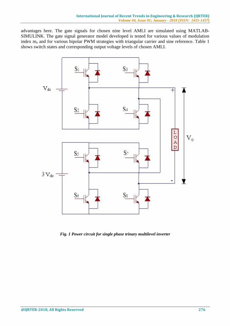
former ones. Figure.1 displays the power circuit for trinary source nine level cascaded inverter. It
looks like a traditional cascaded H-bridge multilevel inverter except that input dc sources are Vdc
and 3Vdc. It can synthesize nine output levels; -4Vdc,-3Vdc, -2Vdc, -Vdc, 0, Vdc, 2Vdc,
3Vdc,4Vdc. Reduced number of dc sources to produce more number of output voltage levels, lower
switching losses, easiness in enhancing the output voltage quality and cost reduction are the salient
International Journal of Recent Trends in Engineering & Research (IJRTER) Volume 04, Issue 01; January - 2018 [ISSN: 2455-1457]
@IJRTER-2018, All Rights Reserved 276
advantages here. The gate signals for chosen nine level AMLI are simulated using MATLAB-
SIMULINK. The gate signal generator model developed is tested for various values of modulation
index ma and for various bipolar PWM strategies with triangular carrier and sine reference. Table 1
shows switch states and corresponding output voltage levels of chosen AMLI.
Fig. 1 Power circuit for single phase trinary multilevel inverter

International Journal of Recent Trends in Engineering & Research (IJRTER) Volume 04, Issue 01; January - 2018 [ISSN: 2455-1457]
@IJRTER-2018, All Rights Reserved 277
Table 1 Switching pattern of TMLI
III. Modulation Strategy:
Variable Amplitude Carriers (VAC)
In this method, all the triangular carriers used will not have the same amplitude. The PWM methods
used are VAPD (Variable Amplitude Phase Disposition) PWM, VAPOD (Variable Amplitude Phase
Opposition Disposition) PWM, VAAPOD (Variable Amplitude Alternate Phase Opposition
Disposition)PWM, VACO(Variable Amplitude Carrier Overlapping)PWM, and VAVF(Variable
Amplitude Variable Frequency)PWM with sine reference. Figure 2 to 6 show the sample reference
waveforms with VA carriers. Figures 7 to 11 show the output voltage and FFT plot and Speed
(steady state) for VAPDPWM, VAPODPWM, VAAPODPWM, VACOPWM, VAVFPWM
strategies. The following parameters are used for simulation. Input DC sources are Vdc = 39V and
3Vdc =117V for binary MLI .
Table 2 Parameter values for Simulation of BCMLI with Induction motor load
Simulation Parameter Value Unit
Switching Frequency (Fs) 1 KHz
DC Source Voltage (Vdc) 156 (39+117) Volts
Rated Output voltage 156 Vp-p
Rated Output frequency 50 Hz
Rated Induction Motor Load 1Φ ,110 VRMS , 186.5 VA,0.25HP
The amplitude modulation index is obtained by
where
Here is the modulation index, is the maximum amplitude of the reference signal and is the
amplitude of the carriers. is the no. of carrier and ‘M’ is no. of levels.
Vout S1 S3 S2 S4 S5 S6 S7 S8
-4Vdc 1 0 0 1 1 0 0 1
-3Vdc 1 1 0 0 1 0 0 1
-2Vdc 0 1 1 0 1 0 0 1
-Vdc 1 0 0 1 1 1 0 0
0 1 1 0 0 1 1 0 0
+Vdc 0 1 1 0 1 1 0 0
+2Vdc 1 0 0 1 0 1 1 0
+3Vdc 1 1 0 1 0 1 1 0
+4Vdc 0 1 1 0 0 1 1 0

International Journal of Recent Trends in Engineering & Research (IJRTER) Volume 04, Issue 01; January - 2018 [ISSN: 2455-1457]
@IJRTER-2018, All Rights Reserved 278
Variable Amplitude Phase Disposition (VAPD) PWM Strategy
With this method all carriers are in phase. For this technique, significant harmonic energy is
concentrated at the carrier frequency. The PD method yields only odd harmonics for odd mf and
yields odd and even harmonics for even mf.Here ma = 0.99 and mf = 20.
Fig. 2. Sample carrier arrangement of VAPD with Sine reference
Variable Amplitude Phase Opposition Disposition (VAPOD) PWM Strategy
With the POD method the carrier waves above the zero reference value are in phase. The carrier
waves below are also in phase but are 180 degrees phase shifted from those above zero. The POD
method yields quarter wave symmetry for even mf and odd symmetry for odd mf .Here ma=0.99 and
mf=20.
Fig. 3. Sample carrier arrangement of VAPOD with Sine reference.
Variable Amplitude Alternative Phase Opposition Disposition (VAAPOD) PWM Strategy
This technique requires each of the four carrier waves, to be phase displaced from each other by 180
degrees alternately. Fig. 4 shows the multicarrier arrangement for APODPWM method for ma =0.99
and mf = 20.

International Journal of Recent Trends in Engineering & Research (IJRTER) Volume 04, Issue 01; January - 2018 [ISSN: 2455-1457]
@IJRTER-2018, All Rights Reserved 279
Fig. 4. Sample carrier arrangement of VAAPODwith Sine reference.
Variable Amplitude Carrier Overlapping(VACO) PWM Strategy
In the Carrier Overlapping strategy, m-1carriers are disposed such that the bands they occupy
overlap each other, the overlapping vertical distance between each carrier is Ac /2.
The reference waveform is centered in the middle of the carrier signals. The vertical offset of carriers
for seven level inverter with VACOPWM strategy is shown in Figure 5.
Fig. 5. Sample carrier arrangement of VACO with Sine reference.
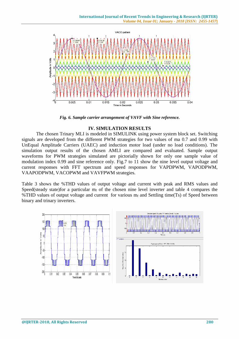
Variable Amplitude Variable Frequency (VAVF) PWM Strategy
The number of switchings for upper and lower devices of chosen seven level single phase cascaded
MLI is much more than that of intermediate switches inconstant frequency carriers. In order to
equalize the number of switchings for all the switches, variable frequency PWM strategy is used as
illustrated in Figure 6, in which the carrier frequency of the intermediate switches is properly
increased for balancing the number of switchings for all the switches.
International Journal of Recent Trends in Engineering & Research (IJRTER) Volume 04, Issue 01; January - 2018 [ISSN: 2455-1457]
@IJRTER-2018, All Rights Reserved 280
Fig. 6. Sample carrier arrangement of VAVF with Sine reference.
IV. SIMULATION RESULTS
The chosen Trinary MLI is modeled in SIMULINK using power system block set. Switching
signals are developed from the different PWM strategies for two values of ma 0.7 and 0.99 with
UnEqual Amplitude Carriers (UAEC) and induction motor load (under no load conditions). The
simulation output results of the chosen AMLI are compared and evaluated. Sample output
waveforms for PWM strategies simulated are pictorially shown for only one sample value of
modulation index 0.99 and sine reference only. Fig.7 to 11 show the nine level output voltage and
current responses with FFT spectrum and speed responses for VAPDPWM, VAPODPWM,
VAAPODPWM, VACOPWM and VAVFPWM strategies.
Table 3 shows the %THD values of output voltage and current with peak and RMS values and
Speed(steady state)for a particular mf of the chosen nine level inverter and table 4 compares the
%THD values of output voltage and current for various mf and Settling time(Ts) of Speed between
binary and trinary inverters.
International Journal of Recent Trends in Engineering & Research (IJRTER) Volume 04, Issue 01; January - 2018 [ISSN: 2455-1457]
@IJRTER-2018, All Rights Reserved 281
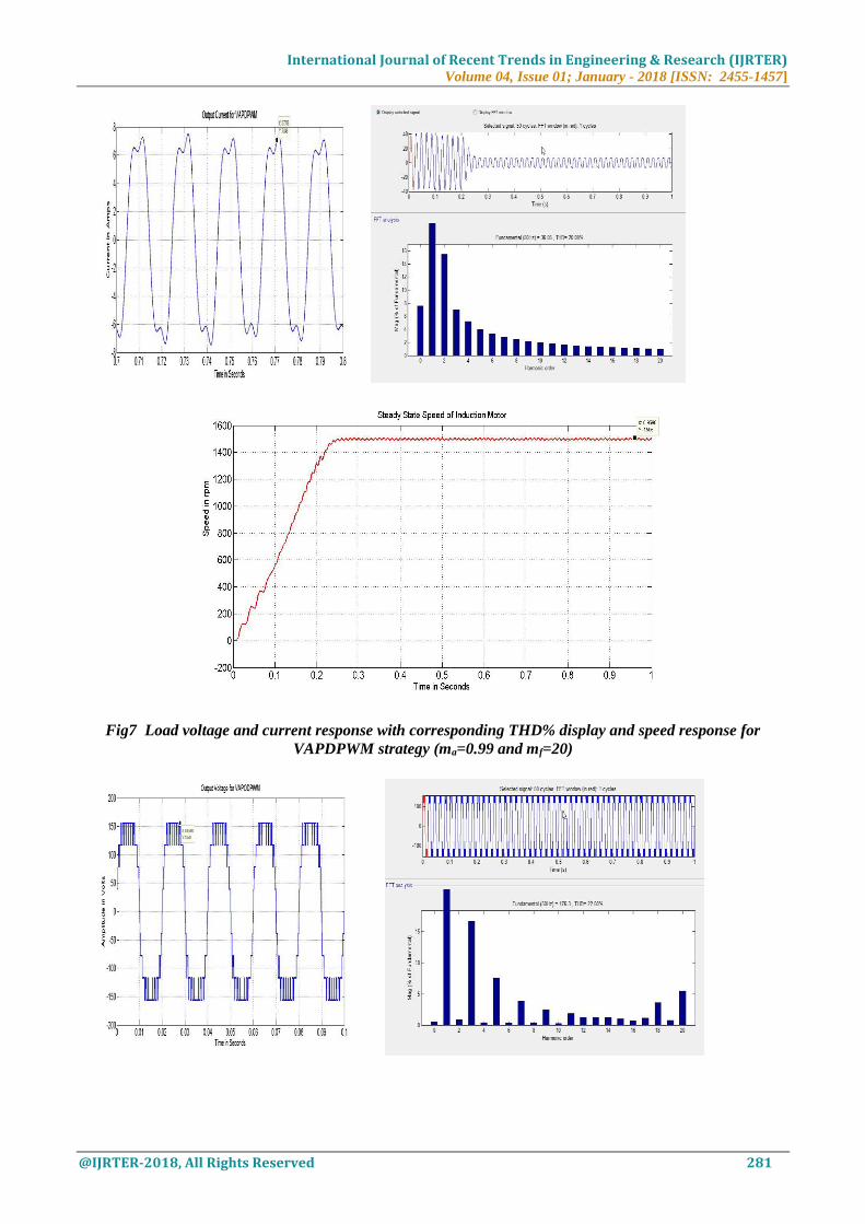
Fig7 Load voltage and current response with corresponding THD% display and speed response for
VAPDPWM strategy (ma=0.99 and mf=20)

International Journal of Recent Trends in Engineering & Research (IJRTER) Volume 04, Issue 01; January - 2018 [ISSN: 2455-1457]
@IJRTER-2018, All Rights Reserved 282
Fig 8 Load voltage and current response with FFT plot and speed response for VAPODPWM strategy
(ma=0.99 and mf=20)

International Journal of Recent Trends in Engineering & Research (IJRTER) Volume 04, Issue 01; January - 2018 [ISSN: 2455-1457]
@IJRTER-2018, All Rights Reserved 283
Fig 9 Load voltage and current response with FFT plot and speed response for VAAPODPWM strategy
(ma=0.99 and mf=20)

International Journal of Recent Trends in Engineering & Research (IJRTER) Volume 04, Issue 01; January - 2018 [ISSN: 2455-1457]
@IJRTER-2018, All Rights Reserved 284
Fig 10 Load voltage and current response with FFT plot and speed response for VACOPWM strategy
(ma=0.99 and mf=20))
Load voltage and current response with FFT plot and speed response for VAVFPWM strategy
(ma=0.99 and mf=20))

International Journal of Recent Trends in Engineering & Research (IJRTER) Volume 04, Issue 01; January - 2018 [ISSN: 2455-1457]
@IJRTER-2018, All Rights Reserved 285
Table 3 Performance evaluation of 9 level Trinary MLI with Induction Motor load for various ma at mf=20
Parameter ma VAPD VAPOD VAAPOD VACO VAVF
THD%
(Voltage)
0.99 23.26 22.5 23 22.27 23.4
0.7 20.09 24 24.09 23.09 22.95
THD%
(Current)
0.99 23.03 19.97 20.53 20.34 20.14
0.7 20.09 20.2 20.32 20.32 20.4
VPeak 0.99 155.9 155.9 155.9 155.9 155.9
0.7 155.9 155.9 155.9 155.9 155.9
VRms 0.99 110 110 110 110 110
0.7 110 110 110 110 110
IPeak
(Initial)
0.99 42.77 42.98 42.44 43.42 42.41
0.7 36.2 35.98 35.92 38.41 36.14
IRms
(Initial)
0.99 30.24 30.39 30 30.7 29.983
0.7 25.59 25.43 25.398 27.155 25.55
IPeak
(steady state)
0.99 7.049 7.293 6.425 7.23 6.935
0.7 6.033 5.635 5.698 6.005 6.03
IRms
(steady state)
0.99 4.98 5.15 4.577 5.11 4.903
0.7 4.265 3.98 4.028 4.245 4.263
Speed
(steady state)
0.99 1505 1501 1504 1502 1503
0.7 1505 1502 1503 1502 1503
International Journal of Recent Trends in Engineering & Research (IJRTER) Volume 04, Issue 01; January - 2018 [ISSN: 2455-1457]
@IJRTER-2018, All Rights Reserved 286
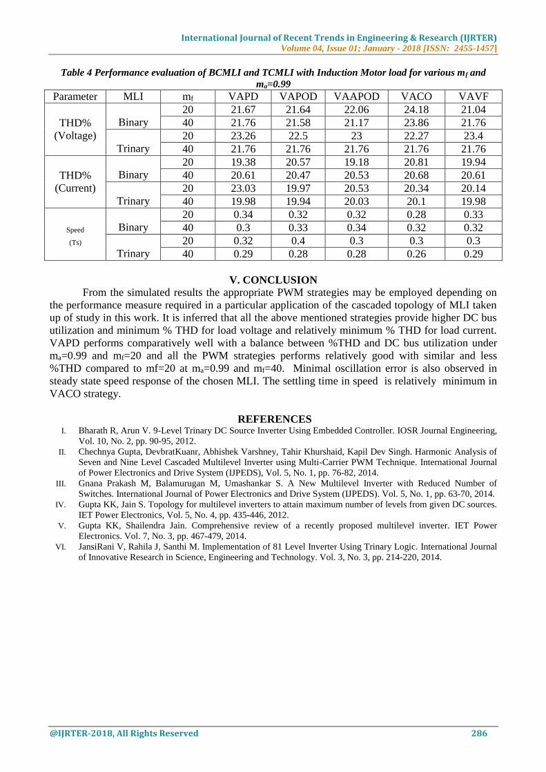
Table 4 Performance evaluation of BCMLI and TCMLI with Induction Motor load for various mf and
ma=0.99
Parameter MLI mf VAPD VAPOD VAAPOD VACO VAVF
THD%
(Voltage)
Binary
20 21.67 21.64 22.06 24.18 21.04
40 21.76 21.58 21.17 23.86 21.76
Trinary
20 23.26 22.5 23 22.27 23.4
40 21.76 21.76 21.76 21.76 21.76
THD%
(Current)
Binary
20 19.38 20.57 19.18 20.81 19.94
40 20.61 20.47 20.53 20.68 20.61
Trinary
20 23.03 19.97 20.53 20.34 20.14
40 19.98 19.94 20.03 20.1 19.98
Speed
(Ts)
Binary
20 0.34 0.32 0.32 0.28 0.33
40 0.3 0.33 0.34 0.32 0.32
Trinary
20 0.32 0.4 0.3 0.3 0.3
40 0.29 0.28 0.28 0.26 0.29
V. CONCLUSION
From the simulated results the appropriate PWM strategies may be employed depending on
the performance measure required in a particular application of the cascaded topology of MLI taken
up of study in this work. It is inferred that all the above mentioned strategies provide higher DC bus
utilization and minimum % THD for load voltage and relatively minimum % THD for load current.
VAPD performs comparatively well with a balance between %THD and DC bus utilization under
ma=0.99 and mf=20 and all the PWM strategies performs relatively good with similar and less
%THD compared to mf=20 at ma=0.99 and mf=40. Minimal oscillation error is also observed in
steady state speed response of the chosen MLI. The settling time in speed is relatively minimum in
VACO strategy.
REFERENCES I. Bharath R, Arun V. 9-Level Trinary DC Source Inverter Using Embedded Controller. IOSR Journal Engineering,
Vol. 10, No. 2, pp. 90-95, 2012.
II. Chechnya Gupta, DevbratKuanr, Abhishek Varshney, Tahir Khurshaid, Kapil Dev Singh. Harmonic Analysis of
Seven and Nine Level Cascaded Multilevel Inverter using Multi-Carrier PWM Technique. International Journal
of Power Electronics and Drive System (IJPEDS), Vol. 5, No. 1, pp. 76-82, 2014.
III. Gnana Prakash M, Balamurugan M, Umashankar S. A New Multilevel Inverter with Reduced Number of
Switches. International Journal of Power Electronics and Drive System (IJPEDS). Vol. 5, No. 1, pp. 63-70, 2014.
IV. Gupta KK, Jain S. Topology for multilevel inverters to attain maximum number of levels from given DC sources.
IET Power Electronics, Vol. 5, No. 4, pp. 435-446, 2012.
V. Gupta KK, Shailendra Jain. Comprehensive review of a recently proposed multilevel inverter. IET Power
Electronics. Vol. 7, No. 3, pp. 467-479, 2014.
VI. JansiRani V, Rahila J, Santhi M. Implementation of 81 Level Inverter Using Trinary Logic. International Journal
of Innovative Research in Science, Engineering and Technology. Vol. 3, No. 3, pp. 214-220, 2014.