Analysis of a DC Motor fed by an Asymetrical single-phase ...
12
American Journal of Engineering Research (AJER) 2021 American Journal of Engineering Research (AJER) e-ISSN: 2320-0847 p-ISSN : 2320-0936 Volume-10, Issue-8, pp: 84-95 www.ajer.org Research Paper Open Access www.ajer.org www.ajer.org Page 84 Analysis of a DC Motor fed by an Asymetrical single-phase bridge rectifier. Irokwe, N. V. 1 , Okoro, C. K. 2 , Oborkhale, L. I. 3 , Kanu, David 4 1,2,3&4 (Dept. of Electrical Electronic Engineering, Michael Okpara University of Agriculture, Umudike, Nigeria) ABSTRACT Direct current (DC) motors have been used for several decades. The DC network was the first developed electric network and was constructed to work on the DC electric network. Nowadays, the majority of industry installed motors consist of AC motors, due to their high-speed operation and their smaller volume and weight. Additionally, AC motors, due to their construction, require lighter maintenance and are cheaper compared to the DC motors. However, DC motors are still used for several reasons, including, wide speed range, starting and accelerating torques more than 400% of their rated values, good speed regulation and simpler and cheaper control systems. This paper presents the design consideration of the asymmetrical single-phase bridge converter.to observe the operation of the dc motor drive, the power circuit and the equivalent circuits of the modes of operation of the asymmetrical DC bridge has been designed and simulated on Matlab/Simulink environment. Each operation model has been presented and shows that operation of DC drives is still exceptional from other industrial drives. The output voltages of DC drives are always positive which makes them necessary for automobile application. DC controlled converters are most favored in applications requiring unidirectional output voltage and current, because in the continuous conduction mode, the have better input power factor compared to most industrial drives. KEYWORDS: Matlab/Simulink, asymmetrical single-phase, Direct-Current (DC)Motor, converter, firing circuit, Rectifier bridge. --------------------------------------------------------------------------------------------------------------------------------------- Date of Submission: 18-07-2021 Date of acceptance: 03-08-2021 --------------------------------------------------------------------------------------------------------------------------------------- I. INTRODUCTION DC motors have been used for several decades. The DC network was the first developed electric network and was constructed to work on the DC electric network. Nowadays, the majority of industry installed motors consist of AC motors, due to their high-speed operation and their smaller volume and weight. Additionally, AC motors, due to their construction, require lighter maintenance and are cheaper compared to the DC motors. However, DC motors are still used for several reasons, including, wide speed range, starting and accelerating torques more than 400% of their rated values, good speed regulation and simpler and cheaper control systems. Their main applications, include manufacture of pulp, paper and paper board, propulsion of electric vehicles, textile industries and public transportation, such as subway and trolley systems. Modern DC motor drives utilize power electronic devices and are subdivided to chopper-fed and controlled thyristor-fed drives. DC motor drives can be categorized according to the way they manage the energy generated during braking of the DC motor [1]. From that point of view, there are non-regenerative and regenerative DC drives in industry. Non-regenerative DC drives are the most conventional type widely used. They have an ability to control motor speed and torque only in one direction DC drives are named as “regenerative” due to the regeneration ability that they offer. During the drive operation in the first and third quadrants, the motor rotation and motor torque have got the same direction and the drive operates as a conventional drive without the regeneration capability. Ability of the drive to convert the mechanical energy produced during the braking condition, into electrical energy. To investigate the problems of harmonics, such as ramp-ups and ramp-downs of a motor during start or stop respectively, there is a need for the introduction of dc drives to control such unwanted harmonics. there is need to carry an exclusive study into the operation modes of the asymmetrical single phase dc converter, and analytically predict its wave shape, the four modes of operation in this investigation includes, the Forward Commutation Interval, Conduction Interval, Free-wheeling Interval and Reverse Commutation Interval. This is
Transcript of Analysis of a DC Motor fed by an Asymetrical single-phase ...

American Journal of Engineering Research (AJER) 2021
American Journal of Engineering Research (AJER)
e-ISSN: 2320-0847 p-ISSN : 2320-0936
Volume-10, Issue-8, pp: 84-95
www.ajer.org Research Paper Open Access
w w w . a j e r . o r g
w w w . a j e r . o r g
Page 84
Analysis of a DC Motor fed by an Asymetrical single-phase
bridge rectifier.
Irokwe, N. V.1, Okoro, C. K.
2 , Oborkhale, L. I.
3 , Kanu, David
4
1,2,3&4 (Dept. of Electrical Electronic Engineering, Michael Okpara University of Agriculture, Umudike, Nigeria)
ABSTRACT Direct current (DC) motors have been used for several decades. The DC network was the first developed
electric network and was constructed to work on the DC electric network. Nowadays, the majority of industry
installed motors consist of AC motors, due to their high-speed operation and their smaller volume and weight.
Additionally, AC motors, due to their construction, require lighter maintenance and are cheaper compared to
the DC motors. However, DC motors are still used for several reasons, including, wide speed range, starting
and accelerating torques more than 400% of their rated values, good speed regulation and simpler and cheaper
control systems. This paper presents the design consideration of the asymmetrical single-phase bridge
converter.to observe the operation of the dc motor drive, the power circuit and the equivalent circuits of the
modes of operation of the asymmetrical DC bridge has been designed and simulated on Matlab/Simulink
environment. Each operation model has been presented and shows that operation of DC drives is still exceptional from other industrial drives. The output voltages of DC drives are always positive which makes
them necessary for automobile application. DC controlled converters are most favored in applications requiring
unidirectional output voltage and current, because in the continuous conduction mode, the have better input
power factor compared to most industrial drives.
KEYWORDS: Matlab/Simulink, asymmetrical single-phase, Direct-Current (DC)Motor, converter, firing
circuit, Rectifier bridge.
---------------------------------------------------------------------------------------------------------------------------------------
Date of Submission: 18-07-2021 Date of acceptance: 03-08-2021
---------------------------------------------------------------------------------------------------------------------------------------
I. INTRODUCTION
DC motors have been used for several decades. The DC network was the first developed electric network and was constructed to work on the DC electric network. Nowadays, the majority of industry installed
motors consist of AC motors, due to their high-speed operation and their smaller volume and weight.
Additionally, AC motors, due to their construction, require lighter maintenance and are cheaper compared to the
DC motors. However, DC motors are still used for several reasons, including, wide speed range, starting and
accelerating torques more than 400% of their rated values, good speed regulation and simpler and cheaper
control systems. Their main applications, include manufacture of pulp, paper and paper board, propulsion of
electric vehicles, textile industries and public transportation, such as subway and trolley systems. Modern DC
motor drives utilize power electronic devices and are subdivided to chopper-fed and controlled thyristor-fed
drives. DC motor drives can be categorized according to the way they manage the energy generated during
braking of the DC motor [1]. From that point of view, there are non-regenerative and regenerative DC drives in
industry. Non-regenerative DC drives are the most conventional type widely used. They have an ability to control motor speed and torque only in one direction DC drives are named as “regenerative” due to the
regeneration ability that they offer. During the drive operation in the first and third quadrants, the motor rotation
and motor torque have got the same direction and the drive operates as a conventional drive without the
regeneration capability. Ability of the drive to convert the mechanical energy produced during the braking
condition, into electrical energy.
To investigate the problems of harmonics, such as ramp-ups and ramp-downs of a motor during start or
stop respectively, there is a need for the introduction of dc drives to control such unwanted harmonics. there is
need to carry an exclusive study into the operation modes of the asymmetrical single phase dc converter, and
analytically predict its wave shape, the four modes of operation in this investigation includes, the Forward
Commutation Interval, Conduction Interval, Free-wheeling Interval and Reverse Commutation Interval. This is

American Journal of Engineering Research (AJER) 2021
w w w . a j e r . o r g
w w w . a j e r . o r g
Page 85
because, as a result of the finite source inductance, current in a thyristor fired at an instant α does not rise instantaneously. Explicit expressions are to be developed in each of these intervals using the piecewise linear
(PWL) method, with the simplifying assumptions that the terminal conditions of one interval are the initial
conditions for the next interval. The waveform of the AC input current is obtained by using the equations
determined for the intervals in a half cycle. The waveform of the input current degenerate as the firing angle of
the drive increases. Fourier integral method was applied to the explicit expressions for the motor input current to
derived equations for the harmonic currents. It has equally been shown by experiments that where a number of
drives are connected to the same AC source, the power factor worsens.
Also, to carry out this investigation properly, dynamic modeling and computer simulation would be
carried out, also to prompt an overall accuracy of the simulation, realistic transmission circuit parameters are
used during simulation so as to create the required harmonics of a motor drives, so as to carry out the study
effectively [2]. Asymmetrical DC drives are basically DC motor speed control system that supplies the voltage to the
motor to operate at desired speed. The dc drive uses the rectification technique of the thyristor bridge to control the
speed of dc motor by varying the DC voltage supplied to the motor. Most dc drives use a couple of thyristors
(SCR’s) to create a half cycle of DC output from a single-phase AC input (half bridge method). The more
advanced ones use 6 SCRs to generate a DC output from a three-phase ac input (full wave bridge). Unlike the ac
drives, the dc drives are famous for providing a high startup torque, having simple circuits and good for application
with constant speed [3]. They are also believed to have more problems especially because of the requirement of
commentator and brush assemblies in the dc motors which require high maintenance. Controlled rectifiers either
single phase or multi-phase are used widely in in asymmetrical dc drive application where ac sources are available.
The single phase or multi-phase ac is converted to dc by a controlled rectifier or converter to give a variable dc
source. by varying the triggering angle of the thyristor or any other power semiconductor device, the speed of the motor can be controlled [4]. Various authors have studied the effects of different conditions of DC motor drives [5-
12], but this paper tends to model a DC Motor fed by an Asymetrical single phase bridge rectifier.
Figure 1: block diagram arrangement of an asymmetrical dc drive
Components of the Asymmetrical Dc Drive The asymmetrical dc drive system consists of only two main components, a converter and a regulator, this can
be further classified into the following components.
1. Rectifier Bridge
2. Speed Regulation (control unit)
3. Firing Circuit
4. Dc Motor & Motor Emf Supply
Rectifier Bridge
A Bridge rectifier is an Alternating Current (AC) to Direct Current (DC) converter that rectifies mains
AC input to DC output. Bridge Rectifiers are widely used in power supplies that provide necessary DC voltage
for the electronic components or devices. They can be constructed with four or more diodes or a combination of
thyristors and diodes, Rectifiers are mainly classified into three types namely half-wave, full-wave, and bridge rectifier. Depending on the load current requirements, a proper bridge rectifier is selected. Components’ ratings
and specifications, breakdown voltage, temperature ranges, transient current rating, forward current rating,
mounting requirements, and other considerations are taken into account while selecting a rectifier power supply
for an appropriate electronic circuit’s application.
Speed Regulation
The dc drives contain the control unit which is responsible for the control of the motor speed and also
the change of direction. the control unit usually consist of a combination of H-bridges and Pulse Width

American Journal of Engineering Research (AJER) 2021
w w w . a j e r . o r g
w w w . a j e r . o r g
Page 86
Modulator such as a 555 IC. The control system usually uses a feedback selection, the whole process starts at the speed reference. a reference signal is given to the drive’s input, which is then fed to the speed controller.
given the amount of speed reference, the speed controller in the microprocessor determines what the output
voltage should be to operate the motor at the desired speed. at the same time, the current controller in the
microprocessor signals the thyristors in the firing unit to gate on. if the feedback is using the EMF measuring
circuit, then the speed measuring/scaling circuit will monitor the armature voltage output. the measuring circuit
will feed back a scaled to the summing circuit. the scaled voltage is in proportion to the output voltage. the
summing circuit will process the reference speed and feedback signal and create and create an error signal. this
error signal is what is used by the speed controller as a new, or corrected, speed command.
Firing Circuit
The function of the firing circuits is to sequentially turn on each thyristor at the proper time, this is accomplished by detecting a reference point with the applied voltage cycle and initiating a firing pulse train after
the proper delay time. The “on” time of the thyristor is increased by decreasing the delay time and vice-versa.it
follows that the output power can be varied by changing the delay time. the delay time is obtained by from a
fixed length electronic counter, counting pulses from an electronic clock, the clock is a voltage-controlled
oscillator. When the clock is at a low frequency, more time is required for the counter to reach its present count,
hence the is a long delay. if the clock frequency is high, the counter needs less time to reach the required count.
when the counter has obtained the required count, meaning the required delay has passed, and assuming no fault
condition exist, an electronic gate opens, allowing firing pulse to turn on the thyristor, this process repeats itself
after every 1200seconds.
DC Motor and Motor emf Supply When the armature is stationary, no motional emf is induced in it. But when the rotor turns, the
armature conductors cut the radial magnetic flux and an emf. is induced in them. As far as each individual coil
on the armature is concerned, an alternating emf will be induced in it when the rotor rotates. the coil will be
moving upward through the flux if the rotation is clockwise, and an emf directed out-of-the rotation plane will
be generated. At the same time the ‘return’ side of the coil will be moving downwards, so the same magnitude
of emf will be generated, but directed into the rotation plane. The resultant emf in the coil will therefore be
twice that in the coil-side, and this emf will remain constant for almost half a revolution, during which time the
coil sides are cutting a constant flux density. For the comparatively short time when the coil is not cutting any
flux, the emf will be zero and then the coil will begin to cut through the flux again, but now each side is under
the other pole, so the emf is in the opposite direction. The resultant emf waveform in each coil is therefore a
rectangular alternating wave, with magnitude and frequency proportional to the speed of rotation [3].
II. MATERIALS AND METHODS
1. Materials
MATLAB/SIMULINK will be used in the design and simulation of the asymmetrical controller and its various
modes of operation, the following blocks will be required in the simulation.
Detailed thyristor block
Diode
Ac Voltage source
Dc motor/Dc source
Resistive and Inductive loads
Pulse generators
Scope
Powergui
2. Methods
Mathematical Modelling of the Dc Motor
Given the general armature equation
= + +
1
The general torque equation is given as
=J
+
2

American Journal of Engineering Research (AJER) 2021
w w w . a j e r . o r g
w w w . a j e r . o r g
Page 87
T=J =J
3
- - - = 0
4
Setting =
5
Substituting values with consideration on shaft output position gives
- -
-
= 0
6
- -
- =0
7
speed and angle
(s)- - (s) - s (s) = 0
8
- –( + )s
9
- –( + )
10
Separating angular speed gives
=
11
(s)=
12
Applying Kirchoff’s law around the field electrical loop by summing voltage throughout the R-L circuit gives
= +
13
Taking Laplace transforms and separating field current give
= (t) +
14
(s)=
15
Applying Kirchoff’s law around the armature electrical
V= - - - EMF = 0
16
Setting EMF=
17
= +
+
18
Taking laplace transforms
(s)= + (s)
+ (s)
19
Separating armature current and field current
(s) =
(s) -
20
(s) =
21 Substituting armature current in eqn. (9)
(s)= - = - + (s)
22

American Journal of Engineering Research (AJER) 2021
w w w . a j e r . o r g
w w w . a j e r . o r g
Page 88
=
23
Can be written in state space as
= Ax + Bu
-a
23
24
25
Transferring the above equation to state space form, in general, state space representation has the form
=Ax+Bu 26
Y=Cx+Du
27
Where,
X is a column vector of dimension ‘n’ called state vector
U is the input of the system
Y is the output of the system
A is the system matrix
B is input matrix C is output matrix
Then
28
29
=
-
30
31
But 32
=
+
33
Y=
34
Since we are using Armature voltage-controlled method
If , Vf , Rf = 0
Hence, Modeling and simulation of the armature voltage-controlled Dc motor. In armature, current controlled
DC motor, the field current is held constant and the armature current is controlled throught the armature
voltage
From eqn. 23 characteristic equation is presented as
+
35
36
Where
= couple resistance

American Journal of Engineering Research (AJER) 2021
w w w . a j e r . o r g
w w w . a j e r . o r g
Page 89
= Mutual inductance
Modes of Operation The operation of the Asymmetrical Bridge may be described by the equivalent circuits representing
each interval of operation as presented in Figure 3.1 In analyzing the circuits for the different intervals, the
terminal conditions of one interval are the initial conditions for the next interval and the simplifying equations
are based on the following assumptions [13-15]
That the thyristor are ideal switches.
That a steady- state condition has been established to justify repetitive representation of the cycles.
Non-linearity in operation of the machine is included in the parameters of the system equations.
That the motor is separately excited and the operating point fixes the parameters of the machine (input power factor problem and correction for industrial drives.
Figure 2: Bridge Converter with half - Cycle Equivalent Circuits
(a) Forward Commutation Interval,
(b) Thyristor Conduction Interval
(c) Freewheeling Interval
(d) Reverse Commutation Interval or Extinction Interval
Analysis for AC Input Current (Piece-Wise Linear Method of Analysis)
Explicit equations for the motor input current of the converter – fed dc motor are derived for the
different intervals below. In applying the piece – wise linear method of analysis, the shift in voltage source
along the time axis for the different intervals is to enable the prediction of currents at the various intervals of
operation. As a result of the finite source inductance, current in the thyristor fired at an instant ω does not rise
instantaneously. In the interval shown in Figure, the thyristor T1 forward commutates and its
current rises to the value of the motor current.
Forward Commutation Interval
This is defined by interval
And having initial condition
Equation for current during this interval is obtained from the equivalent circuit of Figure.2(a) as;
37
Where and are the source supply resistance and inductance respectively. Equation (1) can be solved by
either Laplace function method or integrating factor method Using integrating factor method of solving differential equations, the current at the end of the interval is obtained as [16]
38
The current at the end of the interval when , (t) = ,is then
39
Where
,|z| =
,
,
40
American Journal of Engineering Research (AJER) 2021
w w w . a j e r . o r g
w w w . a j e r . o r g
Page 90
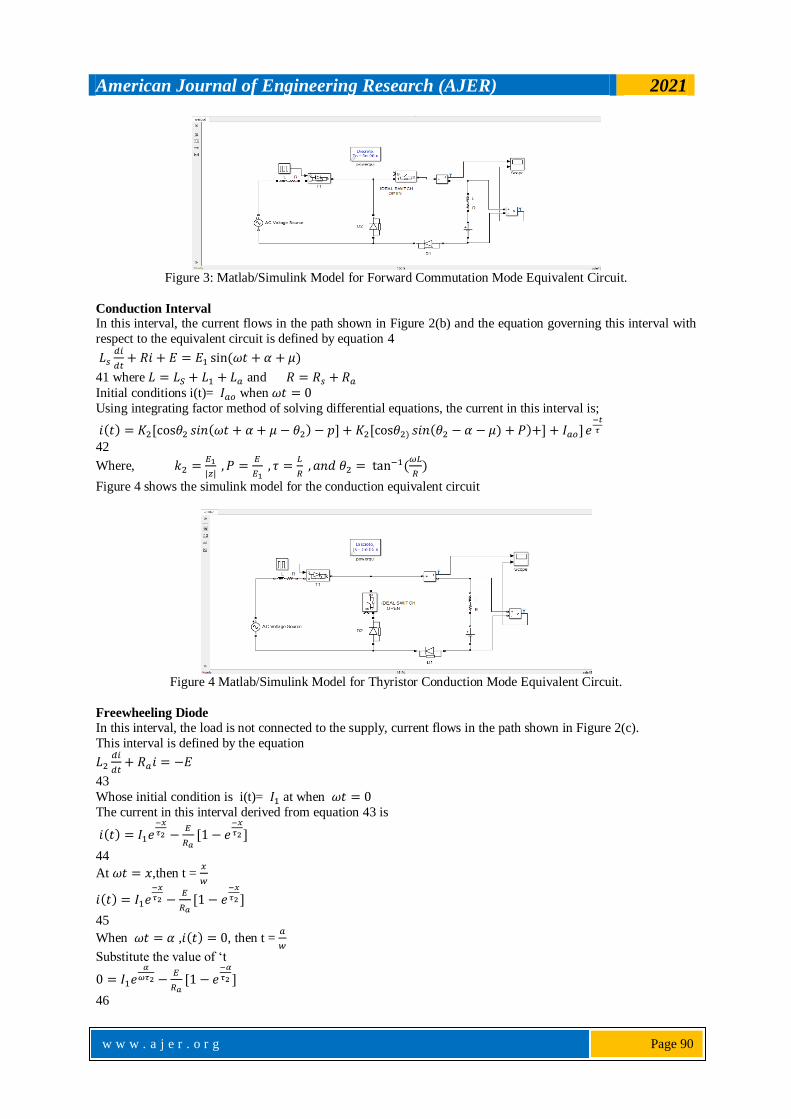
Figure 3: Matlab/Simulink Model for Forward Commutation Mode Equivalent Circuit.
Conduction Interval In this interval, the current flows in the path shown in Figure 2(b) and the equation governing this interval with
respect to the equivalent circuit is defined by equation 4
41 where and
Initial conditions i(t)= when
Using integrating factor method of solving differential equations, the current in this interval is;
42
Where,
Figure 4 shows the simulink model for the conduction equivalent circuit
Figure 4 Matlab/Simulink Model for Thyristor Conduction Mode Equivalent Circuit.
Freewheeling Diode
In this interval, the load is not connected to the supply, current flows in the path shown in Figure 2(c).
This interval is defined by the equation
43
Whose initial condition is i(t)= at when
The current in this interval derived from equation 43 is
44
At ,then t =
45
When , , then t =
Substitute the value of ‘t
46

American Journal of Engineering Research (AJER) 2021
w w w . a j e r . o r g
w w w . a j e r . o r g
Page 91
Therefore;
47
Also, the current at during the conduction interval is equally ‘ ’
.
Therefore , then ,
Hence from equation (47);
48
Equation (39) can be substituted into equation (48) to give a transcendental equation emanating from a
combination of equation (47) and (48) which is solved to obtain the commutation angle, for any gating angle
Figure (5) Shows the variation of the commutation angle ‘μ‘ as the firing angle ‘α‘ is altered
Figure 5: Variation of the Forward commutation angle ‘μ ‘with Firing angle ‘α ‘of a controller at current
4A,5A,6A,7A.
Angle After
The freewheeling diode D2 in Figure 2 (c) becomes forward biased when the instantaneous supply
voltage equals the induced voltage in the source inductance. The induced voltage in the source inductance
reverses biases D2, until the angle after when this voltage is neutralized by the instantaneous supply voltage. The current in the conducting thyristor begins to decay to zero and in attempt to oppose this, the voltage
in the armature circuit inductance forward biases D2 to begin the freewheeling mode.
Figure 6 shows the Matlab/Simulink model for the freewheeling diode mode.
Figure 6: Simulink Model Freewheeling Diode Equivalent Circuit.
Reverse Commutation or Extinction Interval
The reverse commutation of current from a conducting thyristor is opposed by the voltage induced in the source
inductance. Defining from ,the current in the reverse commutating thyristor falls to zero from the value
at ,The equation of current obtained from the equivalent circuit of Figure 2(d) is

American Journal of Engineering Research (AJER) 2021
w w w . a j e r . o r g
w w w . a j e r . o r g
Page 92
49
Re-arranging,
Natural component =
Given that,
Forced response =
where, |z| =
,
therefore, we can obtain
as
50
initial condition,
Hence,
51
Substituting equation (51) in (50)
52
Where,
Figure 3.6 shows the Simulink model of the reverse commutation mode.
Figure 7 Matlab/Simulink Model for Forward Commutation Mode Equivalent Circuit
Conduction Table for the Asymmetrical Converter The operating modes of the asymmetrical converter and the voltage across different devices during these
operating modes are shown in the conduction table1.This table has been prepared with reference to Figure 2.
Table 1: conduction table of single-phase asymmetrical DC drives MODE
T1D2 0 - 0 -
T1D4 0 0 0
T3D4 0 0
T3D2 0 0 - 0
NONE
E
It is observed that whenever D2 conducts the voltage across D4 is and whenever D4 conducts the
voltage across D2 is .Since diodes can block only negative voltage it can be concluded that D2 and D4
conducts in the positive and the negative half cycle of the input supply respectively. Similar conclusions can be
drawn regarding the conduction of T1 and T3. The operation of the converter can be explained as follows when
T1 is fired in the positive half cycle of the input voltage. Load current flows through T1 and D2. If at the
negative going zero crossing of the input voltage load current is still positive it commutates from D2 to D4 and
the load voltage becomes zero. If the load current further continuous till T3 is fired current commutates from T1 to T3. This mode of conduction when the load current always remains above zero is called the continuous
conduction mode. Otherwise, the mode of conduction becomes discontinuous.

American Journal of Engineering Research (AJER) 2021
w w w . a j e r . o r g
w w w . a j e r . o r g
Page 93
III. RESULTS The current and voltage waveforms of the four modes of operation of the asymmetrical single-phase
converter was obtained from the Simulink model, also the four modes of operation of the DC drives are shown.
The results obtain clearly show that as the firing angle of the thyristors of the drive when increased
affects the asymmetrical modes of operation; the instantaneous input current deteriorates which is an indication
of an increased harmonic current present in the supply leading to a low input power factor.
DC Bridge Waveform
The waveform results obtained shows explains the operation of the equivalent circuits for the intervals
of the operation of the dc drive converter and also the sequential conduction of the devices. Figure 4.1 shows the
waveform of the motor input current, to analyze the results, the terminal conduction of one interval is the initial
condition for the next interval.
Figure 8: Simulink Result Showing the DC Input Current Waveform of the Four Operating Interval of the
Asymmetrical Bridge Drive.
Voltage and Current Waveforms of the Equivalent Circuits
Figure 9: Simulink result showing the current and voltage of the equivalent circuit of the forward commutation mode, the waveform does not seem to reverse, thereby avoiding the negative axis returning each time it reaches
the zero mark.

American Journal of Engineering Research (AJER) 2021
w w w . a j e r . o r g
w w w . a j e r . o r g
Page 94
Figure 10: Simulink result the current and voltage waveforms of the equivalent circuit of the freewheeling
interval.
Figure 11: Simulink Result Showing the Current and Voltage Waveforms of The Equivalent Circuit of The
Thyristor Conduction Interval.
Figure 12: Simulink Result Showing the Current and Voltage Waveforms of The Equivalent Circuit Of The
Reverse commutation Interval.
IV. CONCLUSION
This paper presents the design consideration of the asymmetrical single-phase bridge converter.to
observe the operation of the dc motor drive, the power circuit and the equivalent circuits of the modes of
operation of the asymmetrical dc bridge has been designed and simulated on Matlab/Simulink environment.
each operation model has been presented and shows that operation of DC drives is still exceptional from other
industrial drives. Due to their uniqueness of non-operation in the inversion mode, they cannot be used as

American Journal of Engineering Research (AJER) 2021
w w w . a j e r . o r g
w w w . a j e r . o r g
Page 95
inverters unlike most industrial drives. The output voltages of DC drives are always positive which makes them necessary for automobile application. DC controlled converters are most favored in applications requiring
unidirectional output voltage and current, because in the continuous conduction mode, the have better input
power factor compared to most industrial drives.
REFERENCES
[1]. Agu, U “Relative study of the output characteristics of PWM and Phase controlled AC -DC converters”, Conf. Publication, Electric
Power Engineering Conference (EPEC), UNN, 4-5th. Dec. 1997. Pages 132 – 140, 1997.
[2]. Chapman, S.J “Electric Machinery Fundamentals” WCB/McGraw-Hill: New York, NY, USA, 1999.
[3]. Malatestas, P., Motor Drives; Tziolas Publications: Athens Greece, 2013
[4]. Austine Hughes and Bill Drury, Electric Motors and Drives, Fundamentals, Types and Application (4th Edition), 2013
[5]. Fardoun, A. Ismail, E. H. Sabzali, A. J. and Al-Saffar, M. A. “A comparison between three proposed bridgeless Cuk topologies and
conventional topologies for power factor correction,” IEEE Trans. Power Electron., vol. 27, no. 7, pp. 3292–3301, Jul. 2012.
[6]. Wang, H. Tang, Y. and Khaligh, A. “A bridgeless boost rectifier for low voltage energy harvesting applications,” IEEE Trans.
Power Electron., vol. 28, no. 11, pp. 5206–5214, Nov. 2013.
[7]. Huber, L. Jang, Y. and Jovanovic, M. “Performance evaluation of bridgeless PFC boost rectifiers,” IEEE Trans. Power Electron.,
vol. 23, no. 3, pp. 1381–1390, May 2008.
[8]. Chaitanya N Jibhakate, Madhuri A Chaudhari, and Mohan M Renge, “Reactive Power Compensation using Induction Motor driven
by Nine Switch AC-DC-AC Converter”, IEEE Access, Volume 6, pp. 1312 – 1320, December 2017.
[9]. Yun Wei Li, Manish Pande, Navid Reza Zargari, and Bin Wu. “An Input Power Factor Control Strategy for High-Power Current-
Source Induction Motor Drive with Active Front-End”, IEEE Transactions on Energy Conversion, Volume 31, Issue 2, pp. 769-755,
June 2016.
[10]. Ishida, T. Matsuse, K. Miyamoto, T. Sasagawa, K. and Huang, L. “Fundamental characteristics of five-level double converters with
adjustable DC voltages for induction motor drives,”IEEE Trans. Ind. Electron., vol. 49, no. 4, pp. 775–782, Aug. 2002.
[11]. Mohamed, K. M., Haitham, Z. A., Said, A. D., Mohamed, E. D. Power factor correction of three-phase PWM AC Chopper Fed
Induction Motor Drive System using HBCC Technique, IEEE Access Vol 6, pp 43438-43452, 2019
[12]. Jomy, J., Edwina, G. R., Santhosh, R. A., Modified SEPIC Coverter Fed Induction Drive, IOSR Journal of Electrical and
Electronics Engineering (IOSR-JEEE) pp 49-53
[13]. Okoro C. C. “An evaluation of the effects of Ripples on DC machines”. Ph.D Thesis. University of Birmingham, 1980.
[14]. Okoro, C .C, “Performance Evaluation of a D.C. Motor Fed from an Asymmetrical Single – Phase Bridge”,1982, Proc. IEE, Vol.
129, PTB. No.5, pages 289 – 298, 1982
[15]. Okoro C.C. “Behaviour factors of Asymmetrical single-phase converter”. Nigerian Journal of Engineering and Technology, vol.10.
no.11, 1987.
[16]. Osunde .Y, Davidson Otenghabun .S, “Input Power Factor Problem And Correction For Industrial Drives”,Volume 2, Pp. 321-342,
2010.
Irokwe, N. V, et. al. "Analysis of a DC Motor fed by an Asymetrical single-phase bridge
rectifier.”American Journal of Engineering Research (AJER), vol. 10(8), 2021, pp. 84-95.