Comparative Study of R.C.C, Steel and Composite (G+30 Storey ...

ANALYSIS AND DESIGN OF MULTI-STOREY COMPOSITE BUILDING
Mr Nann Tin 1, Dr Tin Tin Win2
1Postgraduate Student, Department of Civil Engineering, Mandalay Technological University, Myanmar
2Director, Myanma Science and Technological Research Department, Ministry of Science and Technology
ABSTRACT: Many types of multistory buildings are the symbols of modernized and developed nations. These buildings are the solution to the problem of living because of population growth. High-rise steel frame and concrete frame structures have been constructed in design of tall buildings in our country as a standard role. But, composite tall building is not situated up to now. Therefore, it is necessary to study special attention in designing the composite tall building. This study deals with composite action in structural members of 5 stories composite building. It belongs to seismic zone 2A. The spans of the sample model are arranged from 10 feet to 30 feet. Analysis of building is carried out by using ETABS Software. In designing beam members, ETABS Software is also used, but CSICOL Software is introduced for column design. Only square sections are used in column design for the purpose of easy to construct the building. The structure is composed of special moment resisting frame by using steel and concrete materials. Seismic load follows the Uniform Building Code (UBC) procedure of equivalent static and dynamic analysis load assumptions and load combinations are also according to UBC provision. In dynamic analysis, response spectrum method is used. Wide flange W-sections are used for frame members associated with reinforced concrete. Floor slabs are designed as metal steel deck supporting concrete slab system. Joints are considered as rigid joints and connection is designed with bolts and weld. Necessary checking is carried out for the stability of the superstructure.
Keywords: composite action, column design, metal deck slab, connection design, dynamic analysis.
1. INTRODUCTION
All high-rise are composite buildings because a functional building cannot be built
by using only steel or concrete. For example, concrete is invariably used for floor
slabs in an otherwise all steel building. Similarly, in a critical sense, use of mild steel
reinforcement transforms a concrete building into a composite building. Without
being too pragmatic, we will settle for the definition of composite buildings as those
with a blend of structural steel and reinforced concrete.
Composite members and some forms of composite systems have been used
extensively somewhere around the world. The history of application of composite
designs back to the last 30 years particularly for member designs. Formalized
design standards and specifications for composite members have involved at slower
pace compared to that of structural steel and reinforced concrete. This is because;
the design standards for composite members have involved from either steel or
concrete design methods.
2nd INTERNATIONAL CONFERENCE ON BUILT ENVIRONMENT IN DEVELOPING COUNTRIES (ICBEDC 2008)
477

The earliest composite construction consisted of structural steel beams and
reinforced concrete slabs, with shear connectors in-between. The system called the
composite floor system, first developed for bridge construction, was readily adopted
to buildings. It phenomenal success inspired engineers to develop composite
building system by combining structural steel reinforced concrete in a variety of
vertical building systems.
2. METHODOLOGY
2.1. Composite Action
Composite action is developed when two load-carrying structural members such
as a concrete floor system and the supporting steel beam are integrally connected
and deflect as a single unit. The extent to which composite action is developed
depends on the provisions made to insure a single linear strain from the top of the
concrete slab to the bottom of the steel section.
When a system acts compositely Fig.1. no relative slip occurs between the
slab and beam. Horizontal force (shears) are developed that act on the lower
surface of the slab to compress and shorten it.
(a) (b)
Figure 1.Comparison of Deflected Beams with and without Composite
Action (a) Deflected Non-composite Beam. (b) Deflected
Composite Beam.
2.2. Composite Elements
To get an insight into different composite building schemes, it is instructive to
study the various techniques of compositing both the horizontal and vertical
elements. These are:
1. Composite slabs or steel concrete floor system.
2. Composite girders.
3. Composite column.
4. Composite diagonals.
5. Composite shear walls.
2nd INTERNATIONAL CONFERENCE ON BUILT ENVIRONMENT IN DEVELOPING COUNTRIES (ICBEDC 2008)
478

2.3. Composite Slabs or Steel Concrete Floor System
Composite floor system can consist of simply supported prismatic or haunched
structural steel beams, trusses or slab girders linked via shear connectors to a
concrete floor slab to form an effective T-beam flexural member. Formed metal deck
supporting a concrete topping slab is an integral component in these floor systems
used nearly exclusively in steel frame buildings.
Figure 2. Beam and Girder with Shear Connectors for
Composite Action with Concrete Slab
2.4. Shear Connectors
Figure 3. Types of Connector. (a) Stud Connectors
(b) Channel Connectors (c) Angle Connectors
2.5. Shear Connector Requirement for Composite Beam
The number of shear connectors required for full composite action is
determined by dividing the smaller value of Vh by the shear capacity of one
(c) (a) (b)
2nd INTERNATIONAL CONFERENCE ON BUILT ENVIRONMENT IN DEVELOPING COUNTRIES (ICBEDC 2008)
479

connector. The number of connectors obtained represents the shear connectors
required between the point of maximum positive moment and point of zero moment.
The total horizontal shear to be resisted between the point of maximum positive
moment and point of zero moment and point of zero moment is the smaller of the
two values as determined by
2
Af0.85V cc
h
′= (2.1)
2
FAV
ys
h = (2.2)
Where, fc' = specified compressive strength of concrete
Ac = actual area of effective concrete flange
As = area of steel beam
Fy = specified yield stress of steel beam
Note that the Equation (2.1) assumes that there is no longitudinal reinforcing
steel in the compression zone of composite beam. If the compressive zone is
designed with mild steel reinforcement, the formula for horizontal shear is to be
modified as follows:
2
FA
2
Af0.85V
yrscch
′+
′= (2.3)
Where, As' = area of the longitudinal compressive steel
Fyr = yield stress of the reinforcing steel
Shear connectors required in the region of negative bending moment and
each point of zero moment. For concentrated loads, the numbers of shear
connectors N2 required between any concentrated load and the nearest point of
zero moment is determined by AISC formula:
1β
1M
MN
Nmax
β
1
2 −
−
= (2.4)
Where, M = moment at concentrated load point (less than the max: moment)
N1= number of connectors required between point of maximum
moment and point of zero moment
Β = ratio of transformed section modulus to steel section modulus
2nd INTERNATIONAL CONFERENCE ON BUILT ENVIRONMENT IN DEVELOPING COUNTRIES (ICBEDC 2008)
480

Figure 4. Shear Connector Requirements for Composite Beams
Subjected to Concentrated Loads
Figure 5. Effective width dimension
The American Concrete Institute (ACI) Code [16.15] has long used the following
effective flange widths for T-sections:
1. For an interior girder,
bE ≤ L/4
bE ≤ bo ( for equal beam spacing)
bE ≤ bf + 16 ts
2. For exterior girder,
bE ≤ bf + L/12
bE ≤ bf + 16 ts
bE ≤ bf + 0.5 (clear distance to next beam)
Point load UDL
M Mmax
N1 = Vh / q
1β
1M
MβN
Nmax
1
2 −
−
=
ts
bE bE
bf b' b' bf b
'
bo bo
2nd INTERNATIONAL CONFERENCE ON BUILT ENVIRONMENT IN DEVELOPING COUNTRIES (ICBEDC 2008)
481

2.6. Composite Column
The ACI code permits the use of any shape inside of a composite column, with a
stipulation that the yield strength of steel cannot be greater than 50 ksi. For tied
columns, the minimum reinforcement ratio is limited to 8 and 6 percent for wind and
seismic designs respectively. The lateral spacing of longitudinal bars cannot exceed
half the length of the shorter side of the section, 16 diameters of the longitudinal bars
or 48 diameters of lateral ties. Two types of columns are used in composite building
systems
(a) (b)
Figure 6. Types of Composite Column (a) Encased Column
(b) Concrete Filled Tubular Column
Figure 7. Shapes of Composite Column (a) Square Column (b) Deep Reinforced
Column (c) Modified Shape for Exterior Column
2.7. Connection for Composite Steel Frame
Interior Moment Connection
Reinforcing steel
Cross Beam
Shear stud
. Exterior Moment Connection
Moment
Connection
Figure 8. Composite Slab Connection Moment-connected Steel Frame
(a) (c)
(b)
2nd INTERNATIONAL CONFERENCE ON BUILT ENVIRONMENT IN DEVELOPING COUNTRIES (ICBEDC 2008)
482

Figure 9. Column Splice
Figure 10. Beam to Column Flange Connection
2.8. Profile of Structures
Proposed model is located in Yangon area. The profiles of this structural model
are listed as follow:
Types of Buildings = 6-storey composite building
Types of Occupancy = Residential
Size of Buildings = Maximum length (59 ft)
Maximum width (40 ft)
Shape of Buildings = Rectangular shape
Height of Buildings = Under Ground Basement (5 ft)
Typical storey height (10 ft)
Bottom storey height (12 ft)
Overall height (65 ft)
W12×58
W12×106
A A
1.753" " 1.75"
6-3/4 in Ø
A325 Bolt
Section A-A
W12×22 W12×50
A
A
Section A-A
1.5" 3"
1.5" 3"
2nd INTERNATIONAL CONFERENCE ON BUILT ENVIRONMENT IN DEVELOPING COUNTRIES (ICBEDC 2008)
483

Figure 11. Ground Floor Plan of Proposed Building
Figure 12. Typical Floor Plan (Storey-1 to Storey-5) of Proposed Building
2nd INTERNATIONAL CONFERENCE ON BUILT ENVIRONMENT IN DEVELOPING COUNTRIES (ICBEDC 2008)
484

Figure 13. Three Dimensional View of Proposed Building
2.9. AISC Design Specifications for Composite Beam
Including provisions for solid slab, there are three categories of composite
beams in the AISC specifications each width a differing effective concrete area.
2.9.1. Solid Slab
The total slab deck is effective in compression unless the neutral axis is
above the top of steel beam. In high-rise floor systems with relatively thin slab the
neutral axis of steel beams is invariably below the slab, rendering the total slab
depth effective in compression.
Figure 14. Solid Slab Beam
2.9.2. Deck Perpendicular to Beam
1. Concrete below the top of steel decking shall be neglected in
computations of section properties and in calculating the number of
2nd INTERNATIONAL CONFERENCE ON BUILT ENVIRONMENT IN DEVELOPING COUNTRIES (ICBEDC 2008)
485

shear studs, but the concrete below the top flange of deck may be
included for calculating the effective width.
2. The maximum spacing of shear connectors shall not exceed 32 in. along
the beam length.
3. The steel deck shall be anchored to the beam either by welding or by
other means at a spacing not exceeding 16 in.
4. A reduction factor as given by the AISC formula I5-1 be used for
reducing the allowable horizontal shear capacity of stud connectors.
1.01h
H
h
w
N
0.85
r
s
r
r
r
≤
−
(4.1)
Where, wr = average width of concrete
Nr = number of studs in one rib
Hr = normal rib height
Hs = length of stud connector
Hs
Wr
hs
Figure 15. Composite Beam with Deck Perpendicular to Beam
2.9.3. Deck Rib Parallel to Beam
1. The concrete below the top of the decking can be included in the
calculations of section properties and must be included when calculating
the number of shear studs.
2. If steel deck ribs occur on supporting beam flanges, it is permissible to
cut high-hat to form a concrete haunch.
3. When normal rib height is 1 ½ in. or greater, minimum average width of
deck flute should not be less than 2 in. for the first stud in the transverse
row plus four stud diameters for each additional stud. This gives
minimum average widths of 2 in. for one stud, 2 in. plus 4 times of
diameter of stud for two studs, 2 in. plus 8 times for three studs, etc.
4. A reduction factor as given by AISC formula I5-2.
1.01h
H
h
w6.0
r
s
r
r ≤
−
(4.2)
2nd INTERNATIONAL CONFERENCE ON BUILT ENVIRONMENT IN DEVELOPING COUNTRIES (ICBEDC 2008)
486

hr=11/2 or greater
wr
Figure 16. Composite Beam with Deck Rib Parallel to Beam
2.10. Design of Composite Steel Deck Slabs
Composite steel deck slabs generally consist of light gage, corrugated or
ribbed, or cellular metal deck forms which interact with a structural concrete topping
as a composite unit to floor loads. The slabs are generally used as one-way slabs
with the steel metal deck acting as reinforcement in the span direction. The
composite steel deck slab is used quite extensively in steel framed buildings and is
usually required to perform the following functions:
1. To act as a construction platform at derrick floors in high-rise buildings.
2. To act as formwork for concrete usually without any shoring between
steel beams. The imposed loads are wet weight of concrete and
construction loads for placement of concrete.
3. To act as a composite slab for all superimposed loads.
4. To act as a diaphragm in distributing shear forces due to wind and
earthquake to various resistive elements and to absorb the stabilizing P-
∆ forces of unbraced columns.
The following criteria are considered in the design of composite slab.
1. Stress shall not exceed 0.6 times the yield strength or 36 kip per square
inch under the combined loads of wet concrete plus deck.
2. Calculated deflection shall be based on the load of the concrete and the
load of deck and shall be limited to L/180 or ¾ inch, whichever is smaller.
3. Under the combined stresses caused by the superimposed live load and
the tensile stresses in the deck, the tensile stress of the deck shall not
exceed 0.6 Fy or 36 kip per inch.
4. The compressive strength in the concrete shall not exceed 0.45 fc'.
5. Deflection of the composite slab shall not exceed L/360 under the
superimposed dead and live load.
6. Steel deck yield strength must be at least 33 ksi and it must be
permanent for the life of the structure.
7. The concrete strength must be at least 3000 psi in accordance with ACI
318.
2nd INTERNATIONAL CONFERENCE ON BUILT ENVIRONMENT IN DEVELOPING COUNTRIES (ICBEDC 2008)
487

8. The minimum diameter of shear connector is ½ in. and maximum
diameter is ¾ in.
9. The minimum center-to-center spacing of studs is six times of stud
diameter and maximum spacing of studs is 32 in.
10. After installation, the studs should extend a minimum of 1 ½ in above the
steel deck.
11. The upset head thickness of the stud is usually 3/8 in. or ½ in. and its
diameter is ½ in. larger than the stud diameter.
12. Rib average width of the deck shall not be less than 2 in.. If the deck
profile is such that the width at the top of the steel deck is less than 2 in.,
this minimum clear width shall be used in the calculation.
13. The section properties do not change a great deal from deck running
perpendicular or parallel to the beam, but the change in the number of
studs can be significant.
14. The depth of deck shall not be less than 3 in.
2.11. Design Procedure for Composite Slabs
2nd INTERNATIONAL CONFERENCE ON BUILT ENVIRONMENT IN DEVELOPING COUNTRIES (ICBEDC 2008)
488

2nd INTERNATIONAL CONFERENCE ON BUILT ENVIRONMENT IN DEVELOPING COUNTRIES (ICBEDC 2008)
489

2.12. Overview of CSICOL Software
This Software can design the column cross-sections for special axial loads and
moments directly or can compute the magnified moments caused by slenderness
effects. In this software, an unlimited number of load combinations can be defined
both for sway and non-sway conditions. Sway and non-sway conditions check may
also be performed as specified in the selected design code. In addition, CSICOL is
capable of determining the Effective Length Factor on the basic of a column’s
framing and end conditions. An auto cross-section design tool helps in automatically
selecting the column size and reinforcement for specified actions using user-defined
rules.
Figure 17. Overview of CSICOL Design and Analysis Process
Defined material
Defined cross-section
Consider Slenderness
Define loading Axial Load
Pu, Top Moment
Mux,Muy
Bottom Moments Mux,Muy
Define Framing Type In X Direction
Lx,Kbx,Kux
In Y Direction Ly, Kby,Kuy
Defined Load Combinations In X Direction In Y direction
For Braced Condition For Unbraced Condition
Magnified Moments for All Loading Combinations
Capacity Check Result
Determine K factor
Using Column Framing Condition
Determine EI Using
EI Calculator
2nd INTERNATIONAL CONFERENCE ON BUILT ENVIRONMENT IN DEVELOPING COUNTRIES (ICBEDC 2008)
490

Table 1. CompareTypical Section for Steel Columns and Composite Columns
Height of column Range of steel column
sections
Range of composite column
sections
0 level to 22 ft W 12 × 152 (12″ × 12″) to (18″ × 18″) with
W6× 9 to W 8 ×67
22 ft to 42 ft W 12 × 106 (10″ × 10″) to (12″ × 12″) with
W6× 20 to W 8 ×67
42 ft to 70 ft W 12 × 58 (10″ × 10″) with
W6× 20 to W 8 ×67
Table 2.Forces and Sizes of Composite Column are calculated by CSICOL Software
Location Axial load ( Pu) kip
Mx(Bot) kip-ft
My(Bot) kip-ft
Mx(Top) kip-ft
My(Top) kip-ft
Column Sizes
Gr-floor (C1)
-227.65 -67.58 -12.05 14.37 -12.68 W6 x25 4# 8 (14″ x 14″)
2nd floor (C1)
-153.1 -20.4 -24.4 21.2 -15.9 W6x16 4# 8 (12″ x 12″)
4rd floor (C1)
-63.8 -14.43 -16.18 13.65 -15.93 W6x16 4# 8 (10″ x 10″)
Gr-floor (C3)
-614.9 -90.53 -46.73 13.37 -31.2 W6x25 4# 8 (18″ x 18″)
2nd floor (C3)
-343.88 -29.63 -86.68 16.84 -23.11 W6x25 4# 8 (16″ x 16″)
4rd floor (C3)
-182.16 -17.514 -47.88 12.96 1.23 W6x25 4# 6 (12″ x 12″)
Gr-floor (C7)
-251.57 -61.84 16.03 -21.9 -0.32 W8x28 4# 6 (14″ x 14″)
2nd floor (C7)
-176.04 -33.98 11.13 30.96 -11.99 W6x25 4# 6 (12″ x 12″)
4rd floor (C7)
-77.62 -22.68 12.33 21.35 -10.97 W6x20 4# 6 (10″ x 10″)
Gr-floor (C9)
-358.32 -71.22 32.48 -7.48 18.42 W6x25 4# 8 (16″ x 16″)
2nd floor (C9)
-266.43 17.39 110.75 -12.51 -87.75 W6x25 4# 7 (16″ x 16″)
4rd floor (C9)
-121.66 8.608 63.05 -7.9 -62.14 W6x25 4# 6 (12″ x 12″)
Gr-floor (C11)
-261.31 54.14 31.83 33.57 -26.27 W6x25 4# 7 (14″ x 14″)
2nd floor (C11)
-193.69 45.13 23.78 39.13 15.11 W6x25 4# 6 (12″ x 12″)
4rd floor (C11)
-90.36 26.2 16.26 -24.05 -12.46 W6x25 4# 6 (10″ x 10″)
Gr-floor (C14)
-228.27 -70.85 12.74 -7.31 5.35 W8x28 4# 6 (14″ x 14″)
2nd INTERNATIONAL CONFERENCE ON BUILT ENVIRONMENT IN DEVELOPING COUNTRIES (ICBEDC 2008)
491
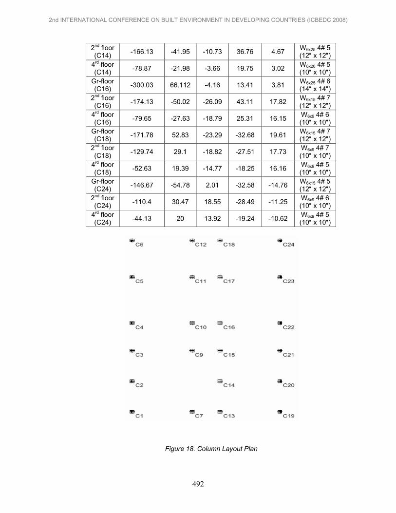
2nd floor (C14)
-166.13 -41.95 -10.73 36.76 4.67 W6x25 4# 5 (12″ x 12″)
4rd floor (C14)
-78.87 -21.98 -3.66 19.75 3.02 W6x20 4# 5 (10″ x 10″)
Gr-floor (C16)
-300.03 66.112 -4.16 13.41 3.81 W6x25 4# 6 (14″ x 14″)
2nd floor (C16)
-174.13 -50.02 -26.09 43.11 17.82 W6x15 4# 7 (12″ x 12″)
4rd floor (C16)
-79.65 -27.63 -18.79 25.31 16.15 W6x9 4# 6 (10″ x 10″)
Gr-floor (C18)
-171.78 52.83 -23.29 -32.68 19.61 W6x15 4# 7 (12″ x 12″)
2nd floor (C18)
-129.74 29.1 -18.82 -27.51 17.73 W6x9 4# 7 (10″ x 10″)
4rd floor (C18)
-52.63 19.39 -14.77 -18.25 16.16 W6x9 4# 5 (10″ x 10″)
Gr-floor (C24)
-146.67 -54.78 2.01 -32.58 -14.76 W6x15 4# 5 (12″ x 12″)
2nd floor (C24)
-110.4 30.47 18.55 -28.49 -11.25 W6x9 4# 6 (10″ x 10″)
4rd floor (C24)
-44.13 20 13.92 -19.24 -10.62 W6x9 4# 5 (10″ x 10″)
Figure 18. Column Layout Plan
2nd INTERNATIONAL CONFERENCE ON BUILT ENVIRONMENT IN DEVELOPING COUNTRIES (ICBEDC 2008)
492
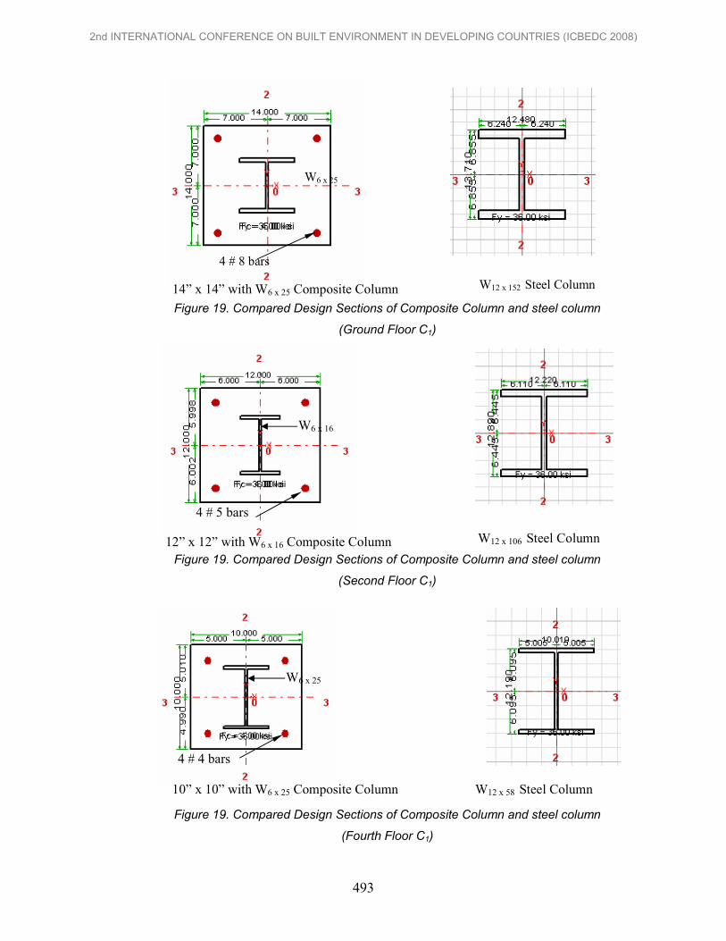
Figure 19. Compared Design Sections of Composite Column and steel column
(Ground Floor C1)
Figure 19. Compared Design Sections of Composite Column and steel column
(Second Floor C1)
Figure 19. Compared Design Sections of Composite Column and steel column
(Fourth Floor C1)
4 # 8 bars
W6 x 25
W12 x 152 Steel Column
4 # 5 bars
W6 x 16
W12 x 106 Steel Column 12” x 12” with W6 x 16 Composite Column
4 # 4 bars
W6 x 25
10” x 10” with W6 x 25 Composite Column W12 x 58 Steel Column
14” x 14” with W6 x 25 Composite Column
2nd INTERNATIONAL CONFERENCE ON BUILT ENVIRONMENT IN DEVELOPING COUNTRIES (ICBEDC 2008)
493

3. DISCUSSION AND CONCLUSION
In this study, five storeys steel frame building with rectangular shape in plan was
selected. The structure was located in zone 2A and 70 feet above ground level. It
was composed of Ordinary Moment Resisting Frame System.The superstructure is
a steel frame building with composite floor system using metal sheeting. Columns
are designed as composite column. In this, W-shaped rolled steel and reinforcing
steel are mixed with concrete.
The design concepts and design load combinations are in accordance with
Load and Resistance Factor Design AISC-LRFD. The superstructure is analyzed
and designed with ETABS Software. CSICOL Software is used in design of
Composite column. Design of floor slabs and connections are manually calculated.
Connections used in the building were bolted and welded connection.
Design provision for seismic and wind forces are based on (UBC 97). All
floor slabs are designed as metal steel deck supporting concrete slab systems.
Dealing with (UBC 97), story-drift, overturning and sliding are checked in the design
calculation. Structural steel used in the building is A 36 steel. Although story drift is
satisfactory, it is close to limit. Therefore, frame with diagonal braced, core braced,
shear wall or core wall structure should be used because of lateral stability.
Connections used in the building were bolted and welded connections. In this study,
bolted connection was mainly used for joint design and welded connection was
considered for erection process. Bearing type connection with 1/4, 3/4, 1 in.
diameters A325 high- strength bolts were considered in this study. Column splice
and base plate design were also presented.
4. REFFERENCES
[1] Williams, A.: Seismic Design of Buildings and Bridges for Civil and structural Engineers, (2003).
[2] Lindeburg, M.R.: A Professional's Introduction of Earthquake Forces and Design Details. In Seismic Design of Building Structures. 8th Edition, Professional Publication, Inc., (2001).
[3] Taranth, B.S.: Steel, Concrete and Composite Design of Tall Building, 2nd Edition, Mc Graw Hill Co. Inc., (1997).
[4] lyengar, S.: Composite or Mixed Steel-concrete Construction for Buildings, (1997).
[5] Gaylord Jr, E.H., Gaylord, C.N. and Stallmeyer, J.E.: Design of Steel Structures, 3rd Edition, Mc Graw Hill Co. Inc., (1992).
[6] Johnson, J.E. and Salmon, C.G.: Steel Structures (Design and Behavior), 3rd Edition, (1986).
[7] Yam, L.C.: Head of Structural Design Division Building Research Station Garston, United Kingdom, (1981).
[8] Lyengar, H.S.: Composite or Mixed steel-concrete construction for Buildings, the Structural Specification Liaison Committee, (1977).
2nd INTERNATIONAL CONFERENCE ON BUILT ENVIRONMENT IN DEVELOPING COUNTRIES (ICBEDC 2008)
494